offshore platform powered with new electrical motor drive ... · pdf fileoffshore platform...
TRANSCRIPT
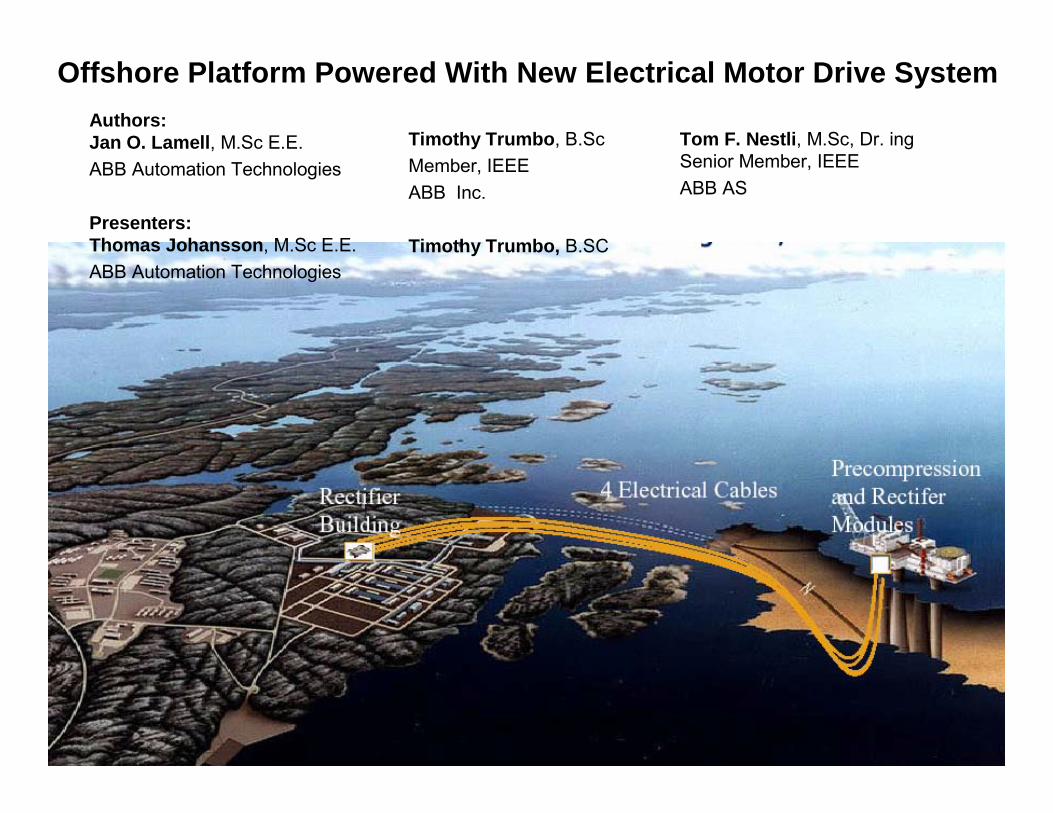
Offshore Platform Powered With New Electrical Motor Drive System
Tom F. Nestli, M.Sc, Dr. ingSenior Member, IEEE ABB AS
Authors:Jan O. Lamell, M.Sc E.E.ABB Automation Technologies
Presenters:Thomas Johansson, M.Sc E.E.ABB Automation Technologies
Timothy Trumbo, B.ScMember, IEEE ABB Inc.
Timothy Trumbo, B.SC

• Background
• The Application
• User Values
• The Technology
• Conclusion

The Application (1)

Boost the Gas Capacity Through the Pipelines to Mainland A new type of compressor motor drive and electrical transmission system is installed
Electrical EnergyPressure
Gas to Mainland
Compressor Motor Drive
AC to DC converterstation
70 km (43 miles)

The Technology (1)

Combining New Technologies
XLPE power cablesHigh Power IGBT

The Business Values (1)

User Values
A Cost Effective Solution Through:• Substancialy Higher System Efficiency• Lower Energy Consumption by Means of Compressor Speedcontrol•No emissions of environmentally harmful substances from the platform

The Case (2)

Typical Power System on Off-Shore Platforms
Loads up to 5-10 MW:
Fuel Supply
Exhaust Gases
Larger Loads:
Fuel Supply
Exhaust Gases

Mechanical Drives
Gas turbine driven compressors result in emissions.In this case:
230 000 tonnes (507 000 000 lbs) of CO2
230 tonnes (507 000 lbs) of Nox
Heavy taxation in the North Sea

Mechanical Drives
Gas turbine driven compressors have limited speed control
• 90-100% speed at same efficiency• 70-100% with lower efficiency
Fuel Supply
Exhaust Gases

Selecting Concept

Evaluation of Gas Turbines vs. Electric Motors
Gas turbines:• Lower investment cost
Electric motors:• No emissions to air• Secure regarding future
environmental constraints• Possible positive effect on
environmental profile• Confident regarding meeting
start up date• Better with regards to
operations, working environment and safety
• Suitable for future low manning mode

Would it not be more cost efficient if..
…we just replaced the gas turbines with electrical motors?
2x 40 MW (53640 HP)
Such large motors (2x40 MW) cannot be fed by the platform electrical system
NOT PASSED

What if....
2 x 40 MW (53 640 HP)
….we supply the motors from shore?
Such powers cannot be transmitted by AC such long distance.
NOT PASSED70 km/43 miles

What if..….we used HVDC transmission?
NOT PASSED
Conventional HVDC transmission requires lots of space, is heavy,and requires a certain “short circuit capacity”.

But How About if ...
….we use the latest technology VSC based HVDC?
NOT PASSED
You still need bulky transformers on the platform.

Not if you use the latest technology VHV motors!
PASSED
The Technology (2)

VSC Based HVDC for Variable Speed Motor Drive
• It is the world’s first VSC based HVDC transmission offshore
• It is the world’s first cable wound VHV motor offshore
• It is the world’s first electrical drive system at 56 kV AC without transformer between inverter and motor.
56 kV ACVSC based HVDC

High Power Voltage Source Converter
Pulse Width Modulation (PWM) withGate Bipolar Transistors (IGBT)
+Ud
-Ud

Higher Voltage Brings Electrical Motors to New Levels
• Experience with motors built for 42 kV and 56 kV.

Technical Highlights on The Motor

Custom Design for a Variable Speed Offshore Motor Installation
Shaft power vs. speed range 1260-1890 rpmRated power 40 MW (53640 hp) @ 1800 rpm
No critical speed within 1070-2160 rpm
Class 1, Zone 1, Group IIA, T3
Electrical supply in terms of voltage, current, and frequency

Mechanical Design
Special concerns:• minimize weight on the platform• weak foundation (skid) on the platform• first bending mode need to be >2160 rpm
=>• Skid dynamic requirements resulted in15 tonnes increased weight.
Skid twist R1, Stator T2, 35.1 Hz
FE-model of Motor20-Skid22

Converter Output Voltage, Current and Frequency
The harmonics content has to be considered carefully in the motor electrical/thermal design.
Converter controller is made to minimize harmonic content.
Voltage waveform results in voltage transients on the insulation screen of the motor cable.
Rise time ≈ 6μs-60kV
+60kV

Cable Stator Winding
The stator winding consists of one continuous cable per phase, each 1.14 km (0.7 miles), without joints.

Cooling System
Water Heat Exchanger Fan
Exiter
Stator
Rotor
Stator Cooling
Fan
Two sub-systems:
Fresh water circuit for stator core, end plates, and slot
Water-to-air cooler for rotor, exciter, and stator winding ends (sea water)
Separate fans to force the inner cooling airflow independently of rotor speed

Suitable Ex Design
Requirement: Class 1, Zone 1, Group IIA, T3
•The motor is of pressurized EEX (p) design with increased safety according to EN 50016
•Temperature class T3 requires that all, internal and external, parts of the machine have maximum surface temperatures of 200°C (392 F).

Motor Protection
All motor protection functions are implemented in the HVDC control and protection system
MOTOR PROTECTION
Description ANS codeDifferential protection 87Overload and over current 49 50/51Negative sequence current 46Harmonic overload 49 51Voltage-frequency (U/f) 24Over speed Over frequency 12 81HStator ground fault 51GLocked rotor and long start 48Over and under excitation 76 37Diode fault 58
I

Motor Testing at Factory
Dielectric testing (on cable, inbetweenwinding, and on complete motor)
Electrical characteristicsNo-load test up to 76 kV
Short-circuit test
Transient reactance, zero and negative sequence reactance, stator impedance
Loss measurements
Heat run tests comprising of three partsNo-load
Short-circuit
Friction

Test Result
The determined efficiency from test for sinusoidal feeding was 97.9%-98.1% for the speed range 70-105%
The balance quality grade of ISO G0.32 (according to ISO 1940)Standard requirements is ISO G2.5
Vibration velocity:
EEX (p) test was successfully completed.

Installation
Weight 500 tonnes (551 ton)Footprint 300 m2 (3229 ft2)
Weight 3500 tonnes(3858 ton)

The Offshore Platform
472 meters high (1549 ft) Total weight: 678 500 tonnesWater depth: 302 meters (991 ft) (747 918 ton)

Overall Schedule
Motor Deliveries January/March 2004Modules Sail Away May 2004Cable Loadout and Installation May-July 2004Spin test January-April 2005Load testing starting June 2005Commercial operation October 2005
System has been tested at 25 MW

Conclusion
• Offshore platform powered by VSC based HVDC• Speed control 40 MW compressors with electrical motors at 56 kV• Significantly higher system efficiency without emissions to air
Key project success factors• Early selection of technical concept• Sufficient time to study, mature and qualify selected technology• Build trust through open, close and good cooperation between all parties• Common and joint approach to problem solving

Thank you!
QUESTIONS?