oif on 400g for next gen optical networks conference
TRANSCRIPT

Defining Requirements and Specifications for 400G & all
Modulations – 200G, 300G, 500G+
NGON 2016
July 30, 2016
Karl Gass
OIF Physical and Link Layer
Committee Vice-Chair for Optics
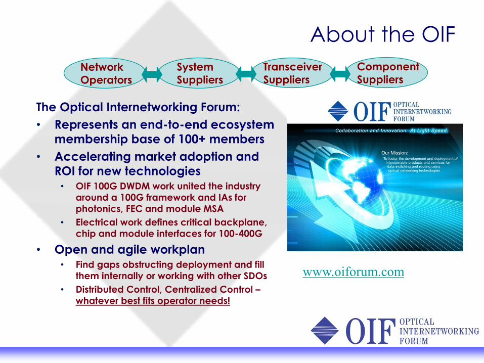
About the OIF
The Optical Internetworking Forum:
• Represents an end-to-end ecosystem
membership base of 100+ members
• Accelerating market adoption and
ROI for new technologies
• OIF 100G DWDM work united the industry
around a 100G framework and IAs for
photonics, FEC and module MSA
• Electrical work defines critical backplane,
chip and module interfaces for 100-400G
• Open and agile workplan
• Find gaps obstructing deployment and fill
them internally or working with other SDOs
• Distributed Control, Centralized Control –whatever best fits operator needs!
www.oiforum.com
Network
Operators
System
Suppliers
Transceiver
Suppliers
Component
Suppliers

PLL Electrical, Protocol and Optical working groups
Looking for opportunities to serve the industry by development of interoperable solutions that are not being addressed by other industry bodies
• Electrical interfaces (Common Electrical Interface)• Protocol interfaces (MLG, Flex E)• Optical interfaces
Publically available, freely shared, Implementation AgreementsBroadly defined so applicable to multiple market segmentsAddressing current industry needs of speed (data rate), density, power efficiency, flexibility (re-use)

Electrical Implementation AgreementsCEI IA is a clause-based format supporting publication of new clauses over time:
• CEI-1.0: included CEI-6G-SR, CEI-6G-LR, and CEI-11G-SR clauses.• CEI-2.0: added CEI-11G-LR clause• CEI-3.0: added work from CEI-25G-LR, CEI-28G-SR • CEI-3.1: added work from CEI-28G-MR and CEI-28G-VSR
CEI-11G and -28G specifications have been used as a basis for specifications developed in IEEE 802.3, ANSI/INCITS T11, and IBTA.CEI 56G projects are in progress:
• LR: backplane• MR: chip to chip• VSR: chip to module• XSR: chip to optics engine (separate chips)• USR: chip to optics engine (2.5D or 3D package)
CEI 112G – under discussion!
2000 2001 2002 2003 2004 2005 2006 2007 2008 2009 2010 2011 2012 2013 2014 2015 2016 2017SxI-5 CEI-1.0 CEI-2.0 CEI-3.0 CEI-3.1
3G 6G11G 25G & 28G 56G 112G

CEI 56G Applications
Host ICModule Connector
AC Coupling
CapModuleRetimer IC
USR
LR
MR
VSR
XSR
Different reaches, number of connectors, channel materials mean we can optimize the application specifications for best efficiencyDifferent modulations provide advantage in certain cases

CEI-56G Application Space
6
� USR: 2.5D/3D applications
� 1 cm, no connectors, no packages
� XSR: Chip to nearby optics engine
� 5 cm, no connectors
� 5-10 dB loss @28 GHz
� VSR: Chip-to-module
� 10 cm, 1 connector
� 10-20 dB loss @28 GHz
� MR: Interfaces for chip to chip and midrange
backplane
� 50 cm, 1 connector
� 15-25 dB loss @14 GHz
� 20-50 dB loss @28 GHz
� LR: Interface for chip to chip over a
backplane
� 100cm, 2 connectors
� 35dB at 14Ghz
Chip-to-Chip & Midplane Applications
Chip-to-Module
Chip Pluggable Optics
CEI-56G-USR
Chip Chip
Backplane or Passive Copper Cable
Chip Chip
3D Stack
CEI-56G-XSR
CEI-56G-VSR
2.5D Chip-to-OE
Optics Chip
Chip to Nearby OE
CEI-56G-MR
CEI-56G-LR
NRZ IA
NRZ & PAM4 IAs
NRZ & PAM4 IAs
NRZ & PAM4 IAs
PAM4 & ENRZ IAs
CEI-56G is leading the drive to higher bandwidths for both networking and data center applications.Projects underway in five link reaches with multiple modulations
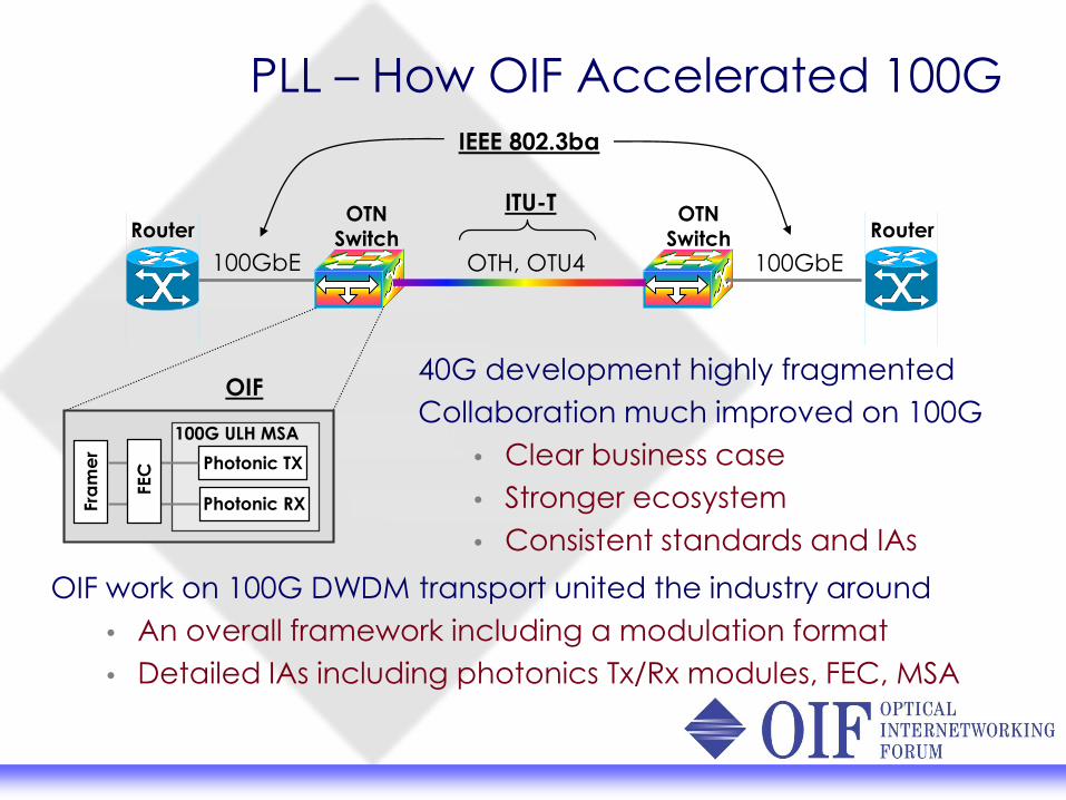
PLL – How OIF Accelerated 100G
Router RouterOTN
Switch
100GbE OTH, OTU4 100GbE
IEEE 802.3ba
ITU-T
OIF40G development highly fragmentedCollaboration much improved on 100G
• Clear business case• Stronger ecosystem• Consistent standards and IAs
Fra
me
r
Photonic TX
Photonic RX
100G ULH MSA
FEC
OTN
Switch
OIF work on 100G DWDM transport united the industry around• An overall framework including a modulation format• Detailed IAs including photonics Tx/Rx modules, FEC, MSA

400G ?
How do we build on our successful deployment of coherent 100G systems?
400G Technology Options White Paperhttp://www.oiforum.com/documents/download-technology-options-for-400g-implementation/
Carrier/User requirements
Survey of modulation formats/options from White Paper
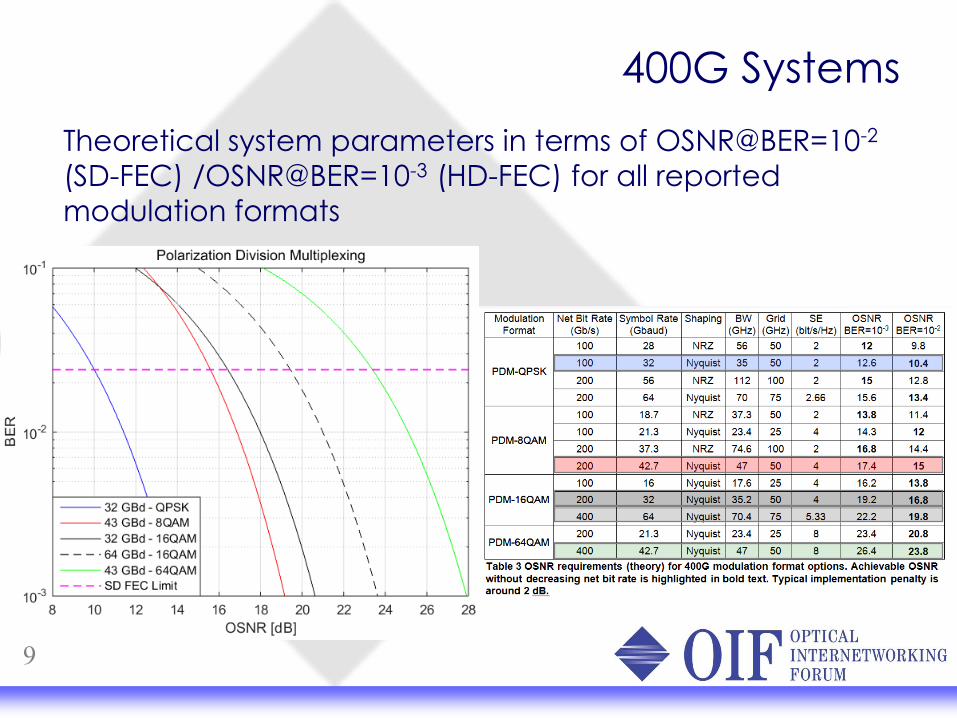
400G SystemsTheoretical system parameters in terms of OSNR@BER=10-2
(SD-FEC) /OSNR@BER=10-3 (HD-FEC) for all reported modulation formats
9

Coherent TransportOptical components still dominate coherent modem system costs and this cost is very volume sensitive. Complexity and system level flexibility at the coherent DSP engine level actually enables a substantial cost savings for the industry since it enables the consolidation of the industry EO component volumes into only three functions.
• This is the strength of the coherent solution for transport.• It has enabled coherent to move into markets not originally
expected [dominates Metro now]
10
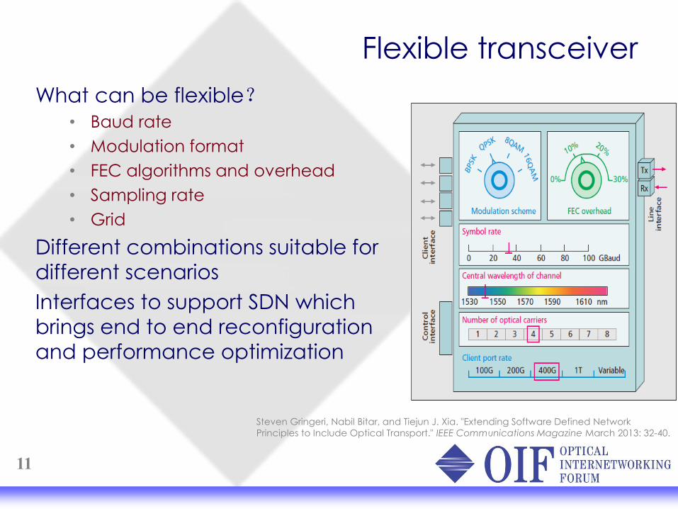
Flexible transceiver
11
What can be flexible?• Baud rate• Modulation format• FEC algorithms and overhead• Sampling rate• Grid
Different combinations suitable for different scenariosInterfaces to support SDN which brings end to end reconfiguration and performance optimization
Steven Gringeri, Nabil Bitar, and Tiejun J. Xia. "Extending Software Defined NetworkPrinciples to Include Optical Transport." IEEE Communications Magazine March 2013: 32-40.

Flexible Coherent DWDM Transmission Framework
Description: • There are different technical approaches for beyond 100G, but
lack of consensus on implementation.• Different from 100G, new features like flex data rate (single chip)
have been incorporated into beyond 100G technology.• Business perspective to improve the investment on the beyond
100G technology elements for both system vendors and component suppliers.
Goal/Scope: This project will develop a Framework:• Technical solution(s) for Flex Coherent Transmission
implementation for different application scenarios: long haul, metro, and data center inter-connection.
• To provide guidance on the hardware implementation, which is given fundamentally by two parameters: the modulated spectrum width and the number of optical carriers.
CFP8-ACO
Description: • A new analog coherent optics (ACO) project that supports
higher baud rate and higher wavelength/carrier-count applications at higher density per wavelength/carrier than the existing CFP2-ACO.
• Up to 4 wavelengths/carriers.• Up to 64 Gbaud per wavelength/carrier.
Utilizes existing CFP8 definition from the CFP-MSA group:• 20W power profile.• The 9.5 mm module height allows for a double stack line card
design or belly to belly. • The 40 mm module width enables a 2 x 8 configuration for a 16
module line card.

Validation of PLL Work: Interop Demos!
Interoperability demos have taken place at OFC and ECOC over the past 4 years demonstrating CEI-25G, CEI-56G and CFP2-ACO
These are interops of OIF member hardware

SummaryOIF has an established history of meeting industry needs for interoperable electrical channels, protocols and optical hardware.
Applications for Backplanes, chip to chip for various reaches, VSR for chip to module, are evolving to meet new requirements and data rates.
Optical solutions are being developed that enable flexibility of deployment in terms of reach and bandwidth
The complete industry benefits when we work together to build an ecosystem.

Thank You!