oil and gas separation design manual
TRANSCRIPT

OIL AND GAS SEPARATIONDESIGN MANUAL

OIL AND GAS SEPARATIONDESIGN MANUAL
BYC. RICHARD SIVALLS, P.E.
SIVALLS, INC.BOX 2792
ODESSA, TEXAS 79760
All rights reserved. This publication is fully protected bycopyright and nothing that appears in it may be printed,either wholly or in part, without special permission.
ievised 1187 Price $5.00

^a\\ \\ZO
Sivalls, Inc.Box2792 Odessa,Texas 797ffi
OIL AND GAS SEPAMTION - DESIGN MANUAL
TABLE OF CONTENTS
T e c h n i c a l B u l l e t i n N o . I 4 2 - O i l a n d G a s S e p a r a t i o n - D e s i g n a n d S i z i n g
I n t r o d u c t i o nC o n s t r u c t i o n o f S e p a r a t o r sS e p a r a t o r T y p e sF a c t o r s A f f e c t i n g S e p a r a t i o nS e p a r a t o r D e s i g n
G a s C a p a c i t yL i q u i d C a p a c i r y
Example Prob lems
F i g u r e 1 - G a s c a p a c i t y o f V e r t i c a l L . p . s e p a r a t o r sF i g u r e 2 A & 2 8 - G a s c a p a c i t y o f v e r t i c a l H . p . s e p a r a t o r sF i g u r e 3 - G a s c a p a c i t y o f H o r i z o n t a l L . p . s e p a r a t o r sF i g u r e 4 4 & 4 B - G a s c a p a c i t y o f H o r i z o n t a l H . p . s e p a r a t o r sF i g u r e 5 4 & 5 8 - L i q u i d C a p a c i t y o f H o r i z o n t a l H . P . S e p a r a t o r sF i g u r e 6 - G a s c a p a c i t y o f s p h e r i c a l L . p . s e p a r a t o r sF i g u r e 7 - G a s c a p a c i t y o f s p h e r i c a l H . p . s e p a r a t o r sF i g u r e 8 & 9 - V e r t i c a l O i l - G a s S e p a r a t o r sF i g u r e 1 0 - H o r i z o n t a l O i 1 - G a s S e p a r a t o r sF i g u r e 1 1 V e r E i c a l O i l - G a s - h l a t e r S e p a r a t o r sF i g u r e L 2 - H o r i z o n t a l o i 1 - G a s - t r r l a t e r s e p a r a t o r sF i g u r e 1 3 - S p h e r i c a l L . p . O i 1 - G a s S e p a r a t o r sF i g u r e L 4 - S p h e r i c a l H . p . O i l - G a s S e p a r a t o r sF i g u r e 1 5 - H o r i z o n t a l H . p . D o u b l e T u b e s e p a r a t o r s
T a b l e 1 A & 1 8 - s p e c i f i c a t i o n s , V e r t i c a l L . p . s e p a r a r o r sT a b l e 2 4 & 2 B s p e c i f i c a t i o n s , v e r t i c a l H . p . s e p a r a t o r sT a b l e 3 4 & 3 8 - s p e c i f i c a t i o n s , H o r i z o n t a l L . p . s e p a r a t o r sT a b l e 4 A & 4 B - s p e c i f i c a t i o n s , H o r i z o n t a l H . p . s e p a r a t o r sT a b l e 5 4 , 5 8 , 5 c - s p e c i f i c a t i o n s , s p h e r i c a l s e p a r a t o r s
R e f e r e n c e s
T e c h n i c a l B u l l e t i n N o . 1 5 9 - T w o S t a g e s e p a r a t i o n S y s t e m
Theory and Tex tEconomicsF igure 1 - Schemat ic F low D iagramF i g u r e 2 - G a s f r o m F l a s h S e p a r a t o rF i g u r e 3 - S t o c k T a n k L i q u i d I n c r e a s e
Page
I1 - 33 - 44 - s
57
9
1 1L 2 - 1 3
L41 5 - L 6L 7 - 1 8
1 92 0
2 I - 2 22 3242 52 62 62 7
2 9
3 234
2 8
3 1
3 6
1 0
30
3 33 5
1 -3
567
34

^a\\ \\ZO
Sivalls, Inc.Box2792 Odegsa,Texas 797ffi
Page
T e c h n i c a l B u l l e t i n N o . 1 6 2 - F i l t e r S e p a r a t o r s
Theory and TextT a b l e 1 & 2 ) C o r r e c t i o n F a c t o r sF i g u r e 1 & 2 , G a s C a p a c i t y o f H o r i z o n t a l F i l t e r S e p a r a t o r s
F i g u r e 3 & 4 , G a s C a p a c i t y o f V e r t i c a l F i l t e r S e p a r a t o r s
F i g u r e 5 , H o r i z o n t a l F i l t e r S e p a r a t o rF i g u r e 6 , V e r t i c a l F i l t e r S e p a r a t o rT a b l e 3 & 4 , S p e c i f i c a t i o n s o f F i l t e r S e p a r a t o r s
T e c h n i c a l B u l l e t i n N o . 1 6 3 - L o w T e m p e r a t u r e G a s S e p a r a t i o n U n i t s
P r o c e s s A p p l i c a t i o nE q u i p m e n t D e s c r i p t i o nR e c o v e r i e sF igure 1 , F low D iagram, Low Tempera ture Separa t ion Un i t
F igure 2 , E f fec t o f Tempera ture on L iqu id Recovery
Re fe rence s
T e c h n i c a l B u l l e t i n N o . 1 7 7 V e r t i c a l G a s S c r u b b e r s
P r o c e s s A p p l i c a t i o nD e s i g n P r o c e d u r e sT a b l e 1 , C o r r e c t i o n F a c t o r sT a b l e 2 , S p e c i f i c a t i o n s o f V e r t i c a l G a s S c r u b b e r s
F i g u r e 1 , G a s C a p a c i t y o f V e r t i c a l G a s S c r u b b e r s
F i g u r e 2 , V e r t i c a l G a s S c r u b b e r
57
:
B9
1 0
46
1 - 22 - 3
3456
123345

^a\\ \\ZO
Sivalls, fnc.Box2792 Odessa,Texas 797ffi
January 1 , 1987 S E C T I O N : 3 0 0TECHNICAL BULLETINN o . L 4 2 , R e v . 5
OIL AND GAS SEPAMTIONDESIGN AND SIZ ING
INTRODUCTION:
Hydrocarbon s t reams as produced a t the we l lhead are composed o f a mix tu re o fg s s , l i q u i d h y d r o c a r b o n s , a n d s o m e t i m e s f r e e w a t e r . I n m o s t c a s e s i t i s d e s i r -a b l e t o s e p a r a t e t h e s e p h a s e s a s s o o n a s p o s s i b l e a f t e r b r i n g i n g t h e m t o t h es u r f a c e a n d h a n d l e o r t r a n s p o r t t h e t w o o r t h r e e p h a s e s s e p a r a t e l y . T h i s s e p -a r a t i o n o f t h e l i q u i d s f r o m t h e g a s p h a s e i s a c c o m p l i s h e d b y p a s s i n g t h ew e l l s t r e a m t h r o u g h a n o i l - g a s o r o i l - g a s - w a t e r s e p a r a t o r .
D i f f e r e n t d e s i g n c r i t e r i a m u s t b e u s e d i n s i z i n g a n d s e l e c t i n g a s e p a r a t o r f o ra h y d r o c a r b o n s t r e a m b a s e d o n t h e c o m p o s i t i o n o f t h e f l u i d m i x t u r e . I n t h ec a s e o f l o w p r e s s u r e o i l w e l l s , t h e l i q u i d p h a s e w i l l b e l a r g e i n v o l u m e a sc o m p a r e d t o t h e g a s p h a s e . I n t h e c a s e o f h i g h p r e s s u r e g a s - d i s t i l l a t e w e 1 l sthe gas vo lume wi l l be h igher as compared to the l iqu id vo lume. The l iqu idp r o d u c e d w i t h h i g h p r e s s u r e g a s i s g e n e r a l l y a h i g h A P I g r a v i t y h y d r o c a r b o n ,u s u a l l y r e f e r r e d t o a s d i s t i l l a t e o r c o n d e n s a t e . H o w e v e r , b o t h 1 o w p r e s s u r eo i 1 w e 1 1 s o r h i g h p r e s s u r e g a s - d i s t i l l a t e w e 1 1 s m a y c o n t a i n f r e e w a t e r .
S e p a r a t o r s a r e u s e d i n m a n y o t h e r l o c a t i o n s o t h e r t h a n a t w e l l h e a d p r o d u c t i o nb a t t e r i e s , s u c h a s g a s o l i n e p l a n t s , u p s t r e a m a n d d o w n s t r e a m o f c o m p r e s s o r s ,a n d l i q u i d t r a p s i n g a s t r a n s m i s s i o n l i n e s . T h e y a r e a l s o f o u n d o n i n l e t s t od e h y d r a t i o n u n i t s , g a s s v / e e t e n i n g u n i t s , e t c e t e r a . A t s o m e o f t h e s e l o c a -t i o n s s e p a r a t o r s a r e r e f e r r e d t o a s k n o c k o u t s , f r e e l i q u i d k n o c k o u t s , a n dt r a p s . S o m e t i m e s t h e s e v e s s e l s a r e c a l 1 e d s c r u b b e r s . C a u t i o n s h o u l d b e u s e dw h e n r e f e r r i n g t o a v e s s e l r e q u i r e d f o r g a s / l i q u i d s e p a r a t i o n a s a s c r u b b e r .W i t h i n t h e g a s i n d u s t r y t h e r e i s a n o t h e r t y p e o f v e s s e l o f t e n c a 1 1 e d a s c r u b b e r .T h i s i s o n e t h a t i s d e s i g n e d t o h a n d l e a g a s s t r e a m w i t h o n l y t r a c e a m o u n t so f f r e e l i q u i d p r e s e n t i n t h e g a s . T h e y a r e n o t d e s i g n e d u s i n g t h e s a m ec r i t e r i a a s i s u s e d f o r g a s / l i q u i d s e p a r a t i o n w h e r e a p p r e c i a b l e a m o u n t s o fl i q u i d a r e p r e s e n t o r w h e r e l i q u i d s l u g g i n g m a y b e e n c o u n t e r e d .
H o w e v e r , a l l o f t h e v e s s e l s m e n t i o n e d a b o v e t h a t a r e d e s i g n e d t o s e p a r a t e g a sa n d f r e e l i q u i d s s e r v e t h e s a m e p r i m a r y p u r p o s e . T h i s t e c h n i c a l p a p e r i s c o n -c e r n e d p r i m a r i l y w i t h t h e u s e o f s e p a r a t o r s i n f i e l d i n s t a l l a t i o n s . T h e t h e o r ya n d b a s i c d e s i g n c r i t e r i a w i l l b e t h e s a m e n o m a t t e r w h e r e t h e y a r e l o c a t e d o rt h e i r b a s i c u s e .
INTERNAL CONSTRUCTION OF SEPAMTORS:
T h e p r i n c i p a l i t e m s o f c o n s t r u c t i o n t h a t s h o u l d b e p r e s e n t i n a g o o d l i q u i d - g a ss e p a r a t o r a r e t h e s a m e r e g a r d l e s s o f t h e o v e r - a l 1 s h a p e o r c o n f i g u r a t i o n o f t h ev e s s e l . s o m e o f t h e s e f e a t u r e s a r e i t e m i z e d a s f o l l o w s :
A c e n t r i f u g a l i n l e t d e v i c e w h e r e t h e p r i m a r y s e p a r a t i o n o f t h el i q u i d a n d g a s i s m a d e .

^a\- 2 - \ \
\ZO
Sivalls, Inc.Box 2792 Odesga, Texas 797ffi
A l a r g e s e t t l i n g s e c t i o n o f s u f f i c i e n t l e n g t h o r h e i g h t t o a l 1 o w
l i q u i d d r o p l e t s t o s e t t l e o u t o f t h e g a s s t r e a m w i t h a d e q u a t es u r g e r o o m f o r s l u g s o f l i q u i d .
A m i s t e x t r a c t o r o r e l i m i n a t o r n e a r t h e g a s o u t l e t t h a t w i l l c o a l e s c e
s m a l 1 p a r t i c l e s o f l i q u i d t h a t w i l l n o t s e t t l e o u t b y g r a v i t y .
A d e q u a t e c o n t r o l s c o n s i s t i n g o fg a s b a c k p r e s s u r e v a l v e r s o f e t ygauge, ins t rument gas regu la to r
l e v e 1 c o n t r o l , l i q u i d d u m p v a l v e ,r e t i e f v a 1 v e , p r e s s u r e g a u g e , l e v e 1a n d p i p i n g .
I t h a s b e e n f o u n d t h a t t h e b u l k o f t h e g a s - l i q u i d s e p a r a t i o n t a k e s p l a c e i n t h e
in le t cen t r i fuga l separa t ing sec t ion . Here the incoming s t ream is spun around
t h e w a l l s o f a s m a l 1 c y l i n d e r o r u s u a l l y t h e w a l l s o f t h e v e s s e l i n t h e c a s e o f
a v e r t i c a l o r s p h e r i c a l s e p a r a t o r . T h i s s u b j e c t s t h e f l u i d s t o a c e n t r i f u g a l
fo rce up to f i ve hundred t imes the fo rce o f g rav i ty . Th is ac t ion s tops the
hor izon ta l mot ion o f the f ree l iqu id en t ra ined in the gas s t ream and fo rces the
l i q u i d d r o p l e t s t o g e t h e r , w h e r e t h e y w i l l f a l l t o t h e b o t t o m o f t h e s e p a r a t o r i n
t h e s e t t l i n g s e c t i o n .
T h e s e t t l i n g s e c t i o n i s n e c e s s a r y t o a l l o w t h e t u r b u l e n c e o f t h e f l u i d s t r e a m
t o s u b s i d e a n d a l l o w t h e l i q u i d d r o p l e t s t o f a l 1 t o t h e b o t t o m o f t h e v e s s e l ,
due to the d i f fe rence in the grav i ty be tween the l iqu id and gas phases . A
la rge open space in the vesse l has been found adequate fo r th is purpose. In t ro -
d u c t i o n o f s p e c i a l q u i e t i n g p l a t e s o r b a f f l e s w i t h n a r r o w o p e n i n g s o n l y c o m p l i -
c a t e s t h e i n t e r n a l c o n s t r u c t i o n o f t h e s e p a r a t o r a n d p r o v i d e s p l a c e s f o r s a n d ,
s l u d g e , p a r a f f i n , € t c e t e r a , t o c o l l e c t a n d e v e n t u a l l y p l u g t h e v e s s e l a n d
s top the f low. I t has been found tha t the separa t ion o f l iqu id and gas us ing
t h e c e n t r i f u g a l i n l e t f e a t u r e a n d a l a r g e o p e n s e t t l i n g s e c t i o n w i l l p r o d u c e a
more s tab le l iqu id p roduc t , wh ich can be ob ta ined in a tmospher ic o r low pres-
sure s to rage tanks . I l i nu te scrubb ing o f the gas phase by use o f in te rna l ba f -
f l i n g o r p l a t e s m a y p r o d u c e m o r e l i q u i d t o b e d i s c h a r g e d f r o m t h e s e p a r a t o r ,
b u t i t w i l l n o t b e a s t a b l e p r o d u c t , s i n c e l i g h t e n d s w i l l b e e n t r a i n e d i n i t ,
a n d , t h e r e f o r e , m o r e v a p o r l o s s e s w i l l b e i n c u r r e d f r o m t h e s t o r a g e s y s t e m .
S u f f i c i e n t s u r g e r o o m s h o u l d b e a l l o w e d i n t h e s e t t l i n g s e c t i o n t o h a n d l e s l u g s
o f l i q u i d w i t h o u t c a r r y o v e r t o t h e g a s o u t l e t . T h i s c a n b e a c c o m p l i s h e d t o
some ex ten t by the p lacement o f the l iqu id leve1 cont ro l in the separa tor wh ich
in tu rn de termines the l iqu id leve l . The amount o f surge room requ i red is
o f t e n d i f f i c u l t , i f n o t i m p o s s i b l e , t o d e t e r m i n e b a s e d o n w e l l t e s t o r f l o w i n g
d a t a . I n m o s t c a s e s t h e s e p a r a t o r s i z e u s e d f o r a p a r t i c u l a r a p p l i c a t i o n i s
o f t e n a c o m p r o m i s e b e t w e e n i n i t i a l c o s t a n d p o s s i b l e s u r g i n g r e q u i r e m e n t s .
A n o t h e r m a j o r i t e m r e q u i r e d t o a f f e c t g o o d a n d c o m p l e t e l i q u i d - g a s s e p a r a t i o n i s
a m i s t e l i m i n a t o r o r e x t r a c t o r n e a r t h e g a s o u t l e t . S m a l l l i q u i d d r o p l e t s t h a t
w i l l n o t s e t t l e o u t o f t h e g a s s t r e a m , d u e t o l i t t l e o r n o g r a v i t y d i f f e r e n c e
between them and the gas phase, w i l l be en t ra ined and pass ou t o f the separa tor
w i t h t h e g a s . T h i s c a n b e a l m o s t e l i m i n a t e d b y p a s s i n g t h e g a s t h r o u g h a m i s t
e l im ina tor near the gas ou t le t wh ich has a la rge sur face imp ingement a rea .
T h e s m a 1 1 l i q u i d d r o p l e t s w i l l h i t t h e s u r f a c e s , c o a l e s c e a n d c o l l e c t a n d f o r m
l a r g e r d r o p l e t s w h i c h w i l l t h e n d r a i n b y g r a v i t y b a c k t o t h e l i q u i d s e c t i o n i n
t h e b o t t o m o f t h e v e s s e l . I t i s b e l i e v e d t h a t t h e s t a i n l e s s s t e e l \ ^ 7 o v e n w i r e
2 .
3 .
4 .
^a\\ \
Sivalls, fnc.Box2792 Odesea,Texas 797ffi\ZO
- 3 -
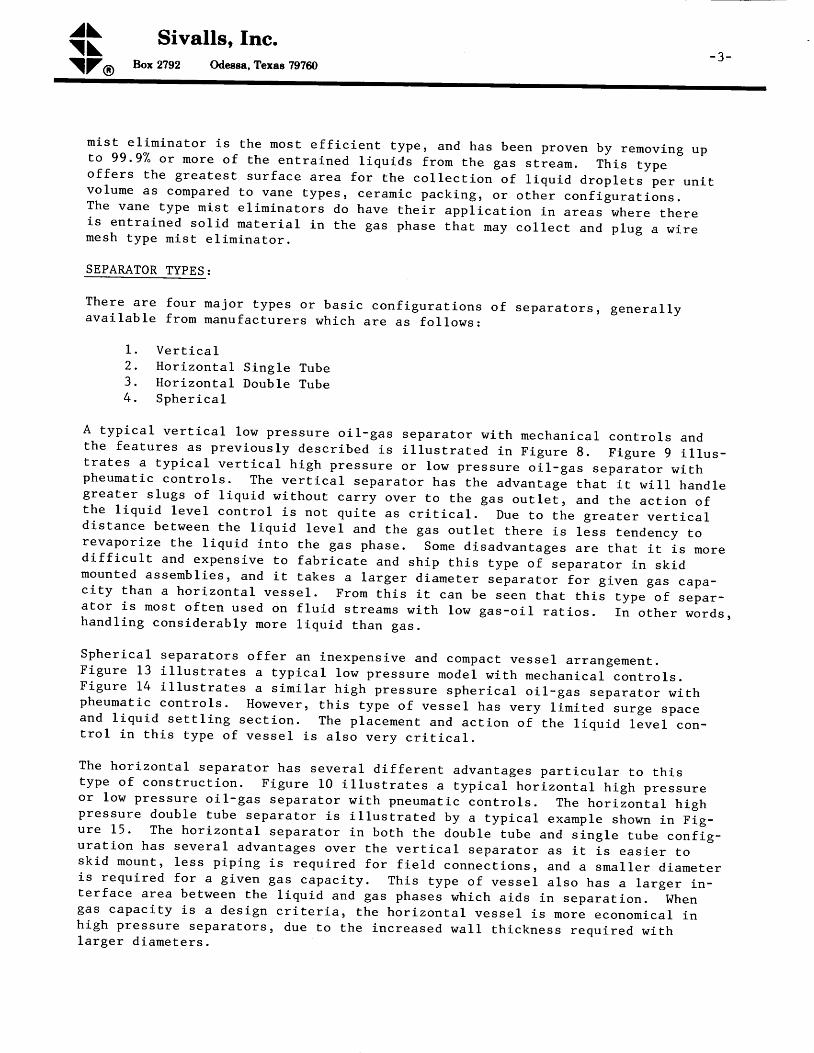
m i s t e l i m i n a t o r i s t h e m o s t e f f i c i e n t t y p e , a n d h a s b e e n p r o v e n b y r e m o v i n g u pt o 9 9 . 9 % o r m o r e o f t h e e n t r a i n e d l i q u i d s f r o m t h e g a s s t i e a m . T h i s t y p eo f f e r s t h e g r e a t e s t s u r f a c e a r e a f o r t h e c o l l e c t i o n o f l i q u i d d r o p l e t s p e r u n i tv o l u m e a s c o m p a r e d t o v a n e t y p e s , c e r a m i c p a c k i n g r o r o t h e r c o n f i g u r a t i o n s .T h e v a n e t y P e m i s t e l i m i n a t o r s d o h a v e t h e i r a p p l i c a t i o n i n a r e a s w h e r e t h e r ei s e n t r a i n e d s o l i d m a t e r i a l i n t h e g a s p h a s e t h a t m a y c o l l e c t a n d p l u g a w i r em e s h t y p e m i s t e l i m i n a t o r .
SEPAMTOR TYPES:
T h e r e a r e f o u r m a j o r t y p e s o r b a s i c c o n f i g u r a t i o n s o f s e p a r a t o r s , g e n e r a l l ya v a i l a b l e f r o m m a n u f a c t u r e r s w h i c h a r e a s f o l l o w s :
1 . V e r t i c a I2 . Hor izon ta l S ing le Tube3. I {o r izon ta l Doub le Tube4. Spher ica l
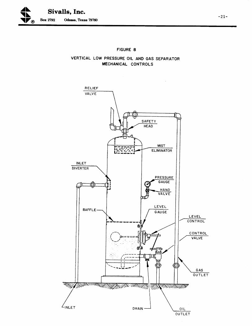
A typ ica l ver t i ca l low pressure o i l -gas separa tor n i th mechan ica l con t ro ls andthe fea tures as prev iousry descr ibed is i r lus t ra ted in F igure g . F igure 9 i l rus -t ra tes a typ ica l ver t i ca l h igh pressure or low pressure o i l_gas separa tor w i thpheumat ic cont ro ls . The ver t i ca l separa tor has the advantage tha t i t w i r r hand legreater s lugs o f l iqu id w i thout car ry over to the gas ou t le i , and the ac t ion o fthe l iqu id leve l con t ro l i s no t qu i te as c r i t i car , Due to the grea ter ver t i ca ld is tance be t r { 'een the l iqu id reve l and the gas ou t le t there is l Jss tendency torevapor ize the r iqu id in to the gas phase. sosre d isadvantages are tha t i t i s mored i f f i cu l t and expens ive to fabr ica te and sh ip th is type o f separa tor in sk id[ounted assembl ies , and i t takes a la rger d ianeter separa tor io r g iven gas capa-c i ty than a hor izon ta l vesse l . F rou th is i t can be seen tha t th iJ type 'o f separ -a to r i s most o f ten used on f lu id s t reams w i th row gas-o i l ra t ios . rn o ther words ,hand l iog cons iderab ly more l iqu id than gas .
Spher ica l separa tors o f fe r an inexpens ive and compact vesse l a r rangement .F igure 13 i l l us t ra tes a typ ica l low pressure mode l w i th mechan ica l con t ro ls .F igure 14 i l l us t ra tes a s imi ra r h igh pressure spher icar o i r -gas separa tor w i thpheurnat ic cont ro ls . However , th is type o f vesse l has very l i rn i tea "u .g" "p r . "and l iqu id se t t l ' i og sec t ion . The p lacement and ac t ion o f the l iqu id r ;ve l con-t ro l in th is type o f vesse l i s a lso very c r i t i ca l ,
The hor izon ta l separa tor has severar d i f fe ren t advantages par t i curar to th istype o f cons t ruc t ion . F igure l0 i l rus t ra tes a typ ica l hor izon ta l h igh pressureor low pressure o i l -gas separa tor w i th pneuuat ic cont ro ls . The hor i -on ia r h ighpressure doub le tube separa tor i s i r lus t ra ted by a typ icar example sho\ , rn i .n F ig -ure 15 ' The hor izon ta l separa tor in bo th the doub le iube and s ing le tube conf ig -ura t ion has severa l advantages over the ver t i car separa tor a8 i t i s eas ie r cosk id mount , less p ip ing is requ i red fo r f ie ld connect ions , and a smal le r d iameteris requ i red fo r a g iven gas capac i ty . Th is type o f vesse l a lso has a la rger in_ter face area be tween the l iqu id and gas phases wh ich a ids in separa t ion , whengas capac i ty i s a des ign c r i te r ia , the hor izon ta l vesse l i s nore economica l inh igh pressure aepara tors , due to the inc reased wa lL th ickness requ i red w i thl a r g e r d i a m e t e r s ,

^a\- 4 -
\ \Sivalls, Inc.
Box 2792 Odessa, Texas 797ffi\ZO
However , the l iqu id leve l con t ro l p lacement i s more c r i t i ca l than in a ver t i ca l
separator and the surge space is somewhat l irnited. The double tube seParator
o f fe rs a s l igh t advantage over the s ing le tube i r r tha t the l iqu id sec t ion is
separa ted f rom the gas space, and there is less chance fo r d is tu rbance o f the
liquid and re-entrainment of any l iquids into the gas phase. I lordever ' the
double tube configuration is rnore expensive.
Three phase or o i l -gas-water sePara t ion can be eas i l y accompl ished in any tyPe
of separa tor by ins ta l l ing e i ther spec ia l in te rna l ba f f l ing to cons t ruc t a water
1eg or water s iphon ar rangement o r by use o f an in te r face l iqu id leve l con t ro l .
A th ree phase fea ture is d i f f i cu l t to ins ta l l in a spher ica l due to the l in i ted
in te rna l space ava i lab le . I { i th th ree phase opera t ion two l iqu id 1eve l con t ro ls
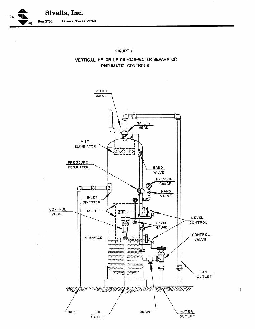
and two liquid durnp val.veg are required. Figure 11 i l lustrates a typical ver-
t i ca l h igh presaure or low pressure aepara tor equ ipped fo r o i l -gas-water th reephase opera t ion . F igure 12 is an i l l us t ra t ion o f a typ ica l hor izon ta l h igh pres-
sure or low pressure o i l -gas- t ta te r sepera tor .
From an evaluation of the advantages and disadvantages of the various tyPes of
separators, the horizontal single tube separator has emerged as the one thatg ives the most e f f i c ien t opera t ion fo r in i t ia l . inveatment coat fo r h igh pres-
sure gas-d i6 t i l l a te we l ls w i th h igh gas-o i1 ra t ios . For h igh l iqu id load ings '
e i ther low pressure or h igh pressure ' ver t i ca l t ype sePara tors shou ld be cons idered.
FACTORS AFFECTING SEPAMTION r
T h e r e a r e s e v e r a l b a s i c f a c t o r s w h i c h w i l l a f f e c t t h e o p e r a t i o n a n d s e p a r a t i o n
b e t w e e n t h e l i q u i d a n d g a s p h a s e s i n a s e p a r a t o t . l
1 . S e p a r a t o r o p e r a t i n g p r e s s u r e2. Separa tor oPera t ing tempera ture3 . F l u i d s t r e a m c o m p o s i t i o n
Changes in any one o f these fac to rs on a g iven f lu id we l ls t ream wi l l change the
a m o u n t o f g a s a n d l i q u i d l e a v i n g t h e s e p a r a t o r . I n m o s t a p p l i c a t i o n s t h e w e l l -
s t r e a m c o m p o s i t i o n i s a f a c t o f n a t u r e a n d c a n n o t b e c o n t r o l l e d b y t h e o p e r a t o r .
On ly in p lan ts o r where severa l s t reams are mixed can the f lu id s t ream compos i -
t i o n b e v a r i e d a f f e c t i n g t h e o i l a n d g a s s e p a r a t i o n . G e n e r a l l y s p e a k i n g ' a n
i n c r e a s e i n o p e r a t i n g p r e s s u r e o r a d e c r e a s e i n o p e r a t i n g t e m p e r a t u r e w i l l
i nc rease the l iqu id covered in a separa tor . However , there are op t imum po in ts
in bo th cases beyond wh ich fu r ther changes w i l l no t a id in l iqu id recovery . In
f a c t , s t o r a g e s y s t e m v a p o r l o s s e s m a y b e c o m e t o o g r e a t b e f o r e t h e s e p o i n t s a r e
r e a c h e d .
In the case o f we l lhead separa t ion equ ipment an opera tor genera l l y wants to
determine the op t imum cond i t ions fo r a separa tor to a f fec t the max imum income.
A g a i n , g e n e r a l l y s p e a k i n g , t h e l i q u i d r e c o v e r e d i s w o r t h m o r e t h a n t h e g a s . S o
h i g h l i q u i d r e c o v e r y i s a d e s i r a b l e f e a t u r e , p r o v i d i n g i t c a n b e h e l d i n t h e
a v a i l a b l e s t o r a g e s y s t e m . A 1 s o , p i p e l i n e r e q u i r e m e n t s f o r t h e B T U c o n t e n t o f
the gas may be another fac to r a f fec t ing the separa tor opera t ion . Wi thout the
a d d i t i o n o f e x p e n s i v e m e c h a n i c a l r e f r i g e r a t i o n e q u i p m e n t i t i s o f t e n n o t f e a s i -
b l e t o t r y t o a f f e c t t h e o p e r a t i n g t e m p e r a t u r e o f a s e p a r a t o r . H o w e v e r r o D m o s t
h i g h p r e s s u r e w e l l s a n i n d i r e c t h e a t e r i s u s e d t o h e a t t h e g a s p r i o r t o

^J\\ \
Sivalls, Inc.
\ZO Box TI92 Odeeea, Texas 797ffi- 5 -
pressure reduc t ion in a choke toth is ind i rec t heater the opera torpr ior to choking, more than whata ture o f the separa tor downst ream
pipe l ine pressure . By care fu l opera t ion o fcan prevent overheat ing of the gas stream
is requ i red , and there fore , a f fec t the temper -f rom the ind i rec t heater .
The opera tor can a lso cont ro l the opera t ing pressure to some ex ten t w i th theuse o f back Pressure va lves w i th in the l im i ta t ion o f the f low ing charac ter is t i cso f the we l l aga ins t a se t p ressure head and the t ransmiss ion l ine pressure re -qu i rements . As prev ious ly ment ioned, h igher opera t ing pressure w i l l genera l l yresu l t in h igher l iqu id recovery .
An ana lys is can be made us ing the we l ls t ream compos i t ion to f ind the op t imumtemperature and pressure at which a separator should operate to give the maxi-mum l iquid and/or gas phase recovery. These calculat ions known as t tFlash Vapor-iza t ion Ca lcu la t ionsr r requ i re a t r ia l and er ro r so lu t ion and more genera l l yadapted to solut ion by a programmed computer. Howeverr 611 operator can alsomake t r ia l se t t ings w i th in the l i rn i ta t ions o f the equ ipment to f ind the bes toperat ing condi t ions to resul t in the maximum amount of gas or l iquids that aredes i red . In the case where separa tors a re used as scrubbers o r knockouts aheadof o ther t rea t ing equ ipment o r compressors , i t i s genera l l y des i red to removethe maximum amount of l iquid f rom the gas stream to prevent operat ional damageto the equ ipment downst ream f rom the scrubber .2
SEPAMTOR DESIGN . GAS CAPACITY:
The gas capac i ty o f o i l -gas separa tors has been ca lcu la ted fo r many years f romthe fo l low ing empi r i ca l re la t ionsh ip p roposed by Souders-Brown.
f ,o. - .a-lYzv = K l r - l
L ' ? g J
T h e n A = gv
W h e r e v = S u p e r f i c i a l g a s v e l o c i t y b a s e d o n t o t a l c r o s s - s e c t i o n a la r e a o f v e s s e l * , f t / s e c
[ = C r o s s - s e c t i o n a l a r e a o f s e p a r a t o r * , s q f tq = Gas f low ra te a t opera t ing cond i t ions r cu f t / sec
P t = D e n s i t y o f l i q u i d a t o p e r a t i n g c o n d i t i o n s , l b / c u f t
4 = D e n s i t y o f g a s a t o p e r a t i n g c o n d i t i o n s , l b / c u f tl ( = Empi r i ca l Fac tor
V e r t i c a l S e p a r a t o r s , 5 t h i g h1 0 ' h i g h
Hor izor ,Ea l Separa tors , 10 t longOther Lengths
S p h e r i c a l S e p a r a t o r sWi re Mesh Mis t E l im ina tors
0 . L 2 t o 0 . 2 4 , a v g0 . 1 8 r o 0 . 3 5 , a v g0 . 4 0 t o 0 . 5 0 , a v g0 . 4 5 [ l ' l o . s o
L l o jS e p a r a t o r L e n g t h ,0 . 2 t o 0 . 3 5 . , a v g0 . 3 5
K -( =l ( =( =
L =( =l ( =
0 . 1 8a . 2 6 50 . 4 5
f t .0 . 2 7 5

^a\- 6 - \ \
\ZO
Sivalls, Inc.Box2792 Odessa,Texas 797ffi
Bubb le Cap Tray Co lumns,24" spacing1 8 t ' s p a c i n g
Va lve Tray Co lumns , 24 t t sPac ing1 8 t t s p a c i n g
V e r t i c a l S c r u b b e r s
l ( =
l ( =( =l ( =
l ( =
0 . 1 60 . 1 20 . 1 80 . 1 10 . 3 5
' k F o r h o r i z o n t a l s i n g l e t u b e s e p a r a t o r s p a r t i a l l y f u l 1 o f l i q u i d '
a n e q u i v a l e n t I . D . m u s t b e d e t e r m i n e d f o r t h e v a p o r a r e a a v a i l a b l e .
The above re la t lonsh ip i s based on a super f i c ia l vapor ve loc i ty th rough a vesee l
and the vapor or gas capacity is then in relationshlP to the diameter of the ves-
sel. The fornule ls also used for other designs, such as trayed towers in de-
hydra t ion or gas sweeten ing un i ts and fo r the s iz ing o f mis t e l im ina tors . There-
fore, the rrKrr factor for these is presented above, along lt ith the factors for ver-
t i ca l and hor izon ta l Bepare tora , so tha t the re la t ionsh ip one bears w i th the
other can be seen.
Where :
a = 2 . 4 0 ( p ) 2 ( K ) ( P ) l a - l v ^z ( r + 4 6 0 ) L P 3
- J
a = Gas capac i ty a t s td cond i t ions ' MMSCFD
D = I n t e r n a t d i a m e t e r , f t . *P = O p e r a t i n g p r e s s u r e , P s i aT = Opera t ing tempera ture ,
oF
Z = C o m p r e s s i b i l i t y f a c t o rA11 o ther i tems as de f ined above
* F o r h o r i z o n t a l s i n g l e t u b e s e p a r a t o r s p a r t i a l l y f u 1 1
o f l i q u i d r d D e q u i v a l e n t I . D . m u s t b e d e t e r m i n e d f o r
the vapor a rea ava i lab le .
S i n c e t h e a b o v e e q u a t i o n i s e m p i r i c a l , p e r h a p s a b e t t e r d e t e r m i n a t i o n o f s e p a r -
a to r gas capac i ty shou ld be made f rom ac tua l manufac turers f ie ld tes t da ta .
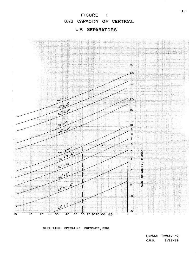
F igures 1 th rough 4 , 6 and 7 are gas capac i ty char ts fo r var ious s tandard s ize
s e p a r a t o r s b a s e d o n o p e r a t i n g p r e s s u r e . T h e s e a c t u a l m a n u f a c t u r e r s g a s c a p a -
c i t y c h a r t s t a k e i n t o c o n s i d e r a t i o n h e i g h t d i f f e r e n c e s i n v e r t i c a l s e p a r a t o r s
and length d i f fe rences in hor izon ta l separa tors wh ich add to the gas capac i ty
o f t h e s e p a r a t o r s . A s c a n b e s e e n , h e i g h t a n d l e n g t h d i f f e r e n c e s a r e n o t t a k e n
in to account in the above Souders-Brown equat ion . But , f ie ld exper ience has
p r o v e n t h a t a d d i t i o n a l g a s c a p a c i t y c a n b e o b t a i n e d b y i n c r e a s e i n h e i g h t o f
v e r t i c a l s e p a r a t o r s a n d c o r r e s p o n d e n l y a d d i t i o n a l l e n g t h o f h o r i z o n t a l s e p a r a -
t o r s .
A s c a n b e s e e n o n t h e s i z i n g c h a r t s f o r h o r i z o n t a L s e p a r a t o r s , a c o r r e c t i o n m u s t
be made fo r the amount o f l iqu id in the bo t tom o f the separa tor . Th is i s fo r
s i n g l e t u b e h o r i z o n t a l v e s s e l s . O n e - h a l f f u l l o f l i q u i d i s m o r e o r l e s s
s tandard fo r most manufac turers fo r s ing le tube hor izon taL separa tors . However ,
t h e g a s c a p a c i t y c a n b e i n c r e a s e d b y l o w e r i n g l i q u i d l e v e l t o i n c r e a s e t h e
a v a i l a b l e g a s s p a c e w i t h i n t h e v e s s e l . G a s c a p a c i t i e s o f h o r i z o n t a l s e p a r a t o r s
w i t h l i q u i d s e c t i o n s o n e - h a l f f u l l , o n e - t h i r d f u 1 l , o r o n e : q u a r t e r f u l l c a n b e
determined f rom the gas capac i ty char ts .

^a\\ \
Sivalls, Inc.
\ZO Box 2792 Odeesa, Texas 797ffi
- 7 -
SEPAMTOR DESIGN - LIQUID CAPACITY:
The l iqu id capac i ty o f a separa tor i s p r imar i l y dependent upon the re ten t iont i m e o f t h e l i q u i d w i t h i n t h e v e s s e l . G o o d s e p a r a t i o n r e q u i r e s s u f f i c i e n tt ime to ob ta in an equ i l ib r ium cond i t ion be tween the l iqu id and gas phase a t thet e m p e r a t u r e a n d p r e s s u r e o f s e p a r a t i o n . T h e l i q u i d c a p a c i t y o f a s e p a r a t o r o rthe se t t l ing vo lume requ i red based on re ten t ion can be de termined f rom the fo l -l o w i n g e q u a t i o n .
I^t = 1440 (V)t
o r t = 1 4 4 0 ( v ) o r V = w ( t )L440I4I
W h e r e : l I = L i q u i d c a p a c i t y , b b l / d a yV = L i q u i d s e t t l i n g v o l u m e , b b lt = Reten t ion t ime, mi -n .
B a s i c d e s i g n c r i t e r i a f o r l i q u i d r e t e n t i o n t i m e s i n s e p a r a t o r s h a v e b e e n d e t e r -m i n e d b y n u m e r o u s f i e l d t e s t s . T h e s e a r e a s f o l l o w s :
Oil -gas separat lon I n in .
I l igh pressure o i l -gas- l re ter separat ion - - - - - - 2 to 5 n ins,
Low presaure o i l -gas-water separat lon 5 to 10 ro ins. @ 100oF and up10 to 15 Eins. @ 90oFL5 to 20 n ins. G 80oF20 to 25 rn ins. @ 70oF25 to 30 n ins. @ 60oF
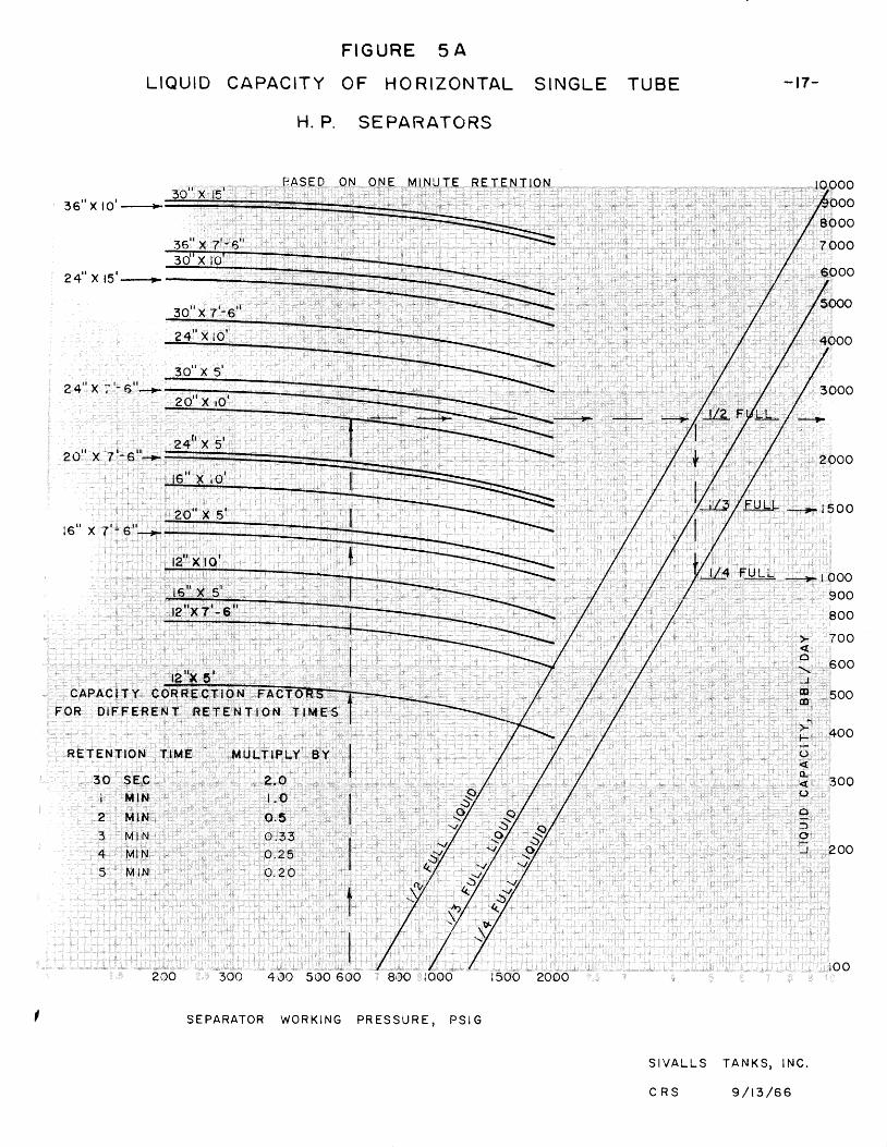
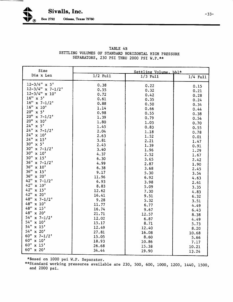
Figures 5A and 58 are s iz ing char ts for the l iqu id capaci ty of hor izonta l s ing letube h igh pressure separators. These are based on the parameters of the separatorwork ing preasure, s ize and the depth of l iqu id used in the set t l ing sect ion.Tables I through 5 l is t the s tandard speci f icat ions of typ ica l o i l -gas separatorsavai lab le, a long rd i th the l iqu id set t l ing vo lumes r r i th the convent ional p lace-ment of l iqu id level contro ls . The set t l ing vo lumes may be used in the aboveequat ions to determine the l iqu id capaci ty of a par t icu lar vessel . For propers iz ing both the l iqu id capaci ty and gas cepaci ty requi red should be detern ined. I tmay be noted that on most h igh pressure gas d is t i l la te wel ls , the gas-o i l ra t iois h igh and the gas capaci ty of a separator is usual ly the contro l l ing factor ,However, the reverse nay be true for low pressure separators used on wellstreansrd i th lord gas-o i l ra t ios. The l iqu id d ischarge or durnp valve on the separatorshould be s ized based upon the pressure drop avai lab le and the l iqu id f low rate,
OTIIER TYPES SEPAMTION EQUIPMENT I
There are several types of separation equipment which employ some of the basicfeatures as d iscussed for o i l and gas separat ion a long l r i th addi t ionel i tems.These types of equipment are d iscusaed in more complete deta i l ln other techni -ca l bu l le t ins. F i l ter separators ernploy ing a dry gas f iL ter in combinat iont r7 i th o i l and gas separat ion are d iscusaed in Technical Bul le t in No. 152 "F iLter
Separators . t l

J
^a\- 8 - \ \
Sivalls, Inc.Box2792 Odesea,Texas 797ffi\ZO
Low temperature separation urxits are another type of equlFtrent enployed for gas-condensete separation of hlgh preaaure gas streams for maximun liquid recovery.The deta i ls and appl icat ion of these uni ts are d iecussed ln Technical BulLet in No.163 rrl,olr Temperature Separation Unlte."
On h igh pressure gas-condensatesepara t ion o f the l iqu ids wh ichwi l l p rov ide a be t te r s tabLLzeds e p a r a t i o n s y s t e m s i s d i s c u s s e da t i o n S y s t e m s . t t
s t reams i t i s o f ten advantageous to employ s tagerequ i re the use o f two or more separa tors . Th isl iqu id p roduc t . The use and app l ica t ion o f s tagein Techn ica l Bu l le t in No. 159, "Two Stage Separ -
I {here on ly t race or smal l amounts o f f ree l iqu id a re found in the gas s t ream,i t may be poss ib le to use a ver t i ca l gas scrubber to remove the l iqu id f rom theg a s . T h i s t y p e o f v e s s e l i s d i s c u s s e d m o r e c o m p l e t e l y i n T e c h n i c a l B u l l e t i n N o .L 7 7 , t r V e r t i c a l G a s S c r u b b e r s . t t C a u t i o n s h o u l d b e u s e d i n t h e a p p l i c a t i o n o ft h e s e v e s s e l s i n t h e p l a c e o f a c o n v e n t i o n a l d e s i g n e d g a s / l i q u i d s e p a r a t o r .Scrubbers shou ld be used on ly where no apprec iab le amounts o f f ree l iqu id a represent in the gas s t ream or no l iqu id s lugg ing is to be encountered .
CONCLUSION:
The above described sizing procedures and accompanyLng charts and tables offer anaccurate procedure for s iz lng standard o i l f ie ld o i l -gas aeparators for h igh pres-sure gas condensate nel ls t reems or low pressure o i ls t reams. Of course, thesecharts and tables can be used in any reverse manner for evaluating and deterEin-lng the capacity or performance of existing equipment. The following exanples arepresented to further il lustrate the use of the charts end tabLes and methods tobe used in e iz ing o i l -gas separat ion equipment .
^a\ cii Sivalls, fnc.\ZO Box 2792 Odesea, Texas 797ffi
- 9 -
HilI"IPLE PROBLEMS
Ex?grple 1: size a atandard oil-gas aeparator both vertical and horizontal for thefollowing condltlons.
Gas Flow Rate: 5. 0 MMSCFDOpera t ing Pressure : 800 ps igCondensate F low Rare : 20 bb1/MMSCF
Tota l L iqu id Capac i ty = 20 (5 .0 ) = 100 bb l /day
From F igure 2A, a t 800 ps ig opera t ing pressure , a 20 t t x 7 t -6 t t ver t i ca l separa torw i l l hand le 5 .4 MMSCFD.
From Tab le 28 , a 20" x 7 t -6 t t separa tor w i l l hand le the fo l low ing l iqu id eapac i ty .
I ^ l = 1440 (v ) = 1440 (0 . 65) = 936 bb l /dayt 1 . 0
From F igure 4A, a t 800 ps ig opera t ing pressure and 7 /2 fu l - l o f l iqu id , a 16" x 5 fhor izon ta l separa tor w i l l hand le 5 .1 MMSCFD.
From Tab le 48 , a 16" x 5 t separa tor w i l l hand le .
w = 1440 (v) = 1440 (0.51) = 878 bbl/dayr 1 . 0
Therefore, a smaller horizontal separator would be reguired and r+ou1d be moreeconornical. For the operating pressure invoJ-ved, at least a L000 pstg workingpressure separator should be used.
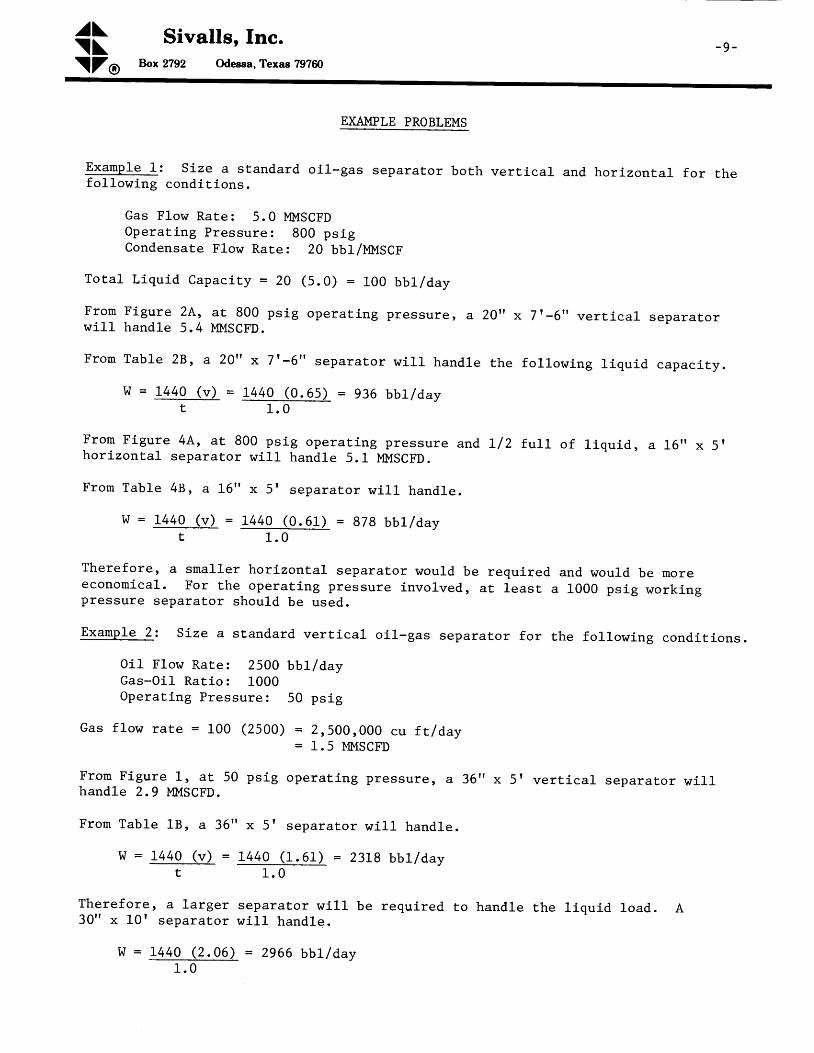
Example 2: Slze a standard vertical oll-gas separator for the followlng conditions.
0i1 Flow Rates 2500 bbll d,aycas-oil Raclo: L000Operat ing Pressure: 50 ps ig
Gas f low rate = L00 (2500) = 2,500,000 ct f t lday= 1.5 MMSGFD
From FLgure 1, a t 50 ps ig operat lng pressure, a 35r 'x 5r ver t ica l separator wi l lhandle 2.9 MMSCFD.
Fron TabLe 18, a 36" x 5' separator will handle.
w = 1440 (v) = 1440 (1.61) = 2318 bbL/dayt 1 . 0
Therefore, a larger separator wi l l be required to handle the l iquid 1oad. A30" x 10r separator wi l l handle.
W = 1440 (2 .06) = 2966 bbL /day1 . 0

^a\ Sivalls, Inc.- 1 0 - \ \
\ZO Box 2792 Odegsa, Texas 797ffi
The gas capacity of a 30" x 10r separator is 3.75 MMSCI'D ' In fact' the diameterof a aeparator generall"y controls the price and a 30" x 10r separator willprobably be cheaper than a 36" x 5'.
Exanple 3: A 20" x 10t, 100 psl W.P. horlzontal seParator is operated at l/2 frtLLof J-1qu1d. It can be used on a well with the followi,ng conditions.
Gas Ilow Rate: 9.0 I,IMSCFDLlne Pressure: 500 pslg
From Flgure 44, a 20" x 1-0r separator will handle only 8.1 IIMSCFD at 500 psig.
But, if a gas back pressure valve were Put oo the seParator and held at 800 psig'
the separator w111 handle 10'2 !'IMSCFD. This ls accePted procedure Providing thewell w111 fl-on the deslred rate at 800 pslg.
Example 4: SLze a horlzontal hlgh pressure separator for the folJ-owing conditions.
Gas Fl-ow Rate: 10.0 MMSCFDoperating Pressute: 800 pslgCondensate Load: 500 bbl/daywater Load: 100 bbl/day
FroE Figure 44, at 800 psig operatlng Pressure, a 2Q" x 10r horizontal seParatorw111 handle 10.2 MMSCFD operating L/2 fuLL of liquld' Where lhree Phase oPerationIs required in a horlzontal separator, the liquid section should be Il2 f'uLL,otherwise the leveL control action becomes too crltlcal.
Fron Table 48, the liquid capacity wiLl be.
w = 1 4 4 0 ( v ) = 1 4 4 0 ( 1 . 8 9 ) = 5 1 8 b b 1 / d a yt 5 . 0
Therefore, the 20" x 10t separator wi l l not handle the combined l iquid load of
500 + 100 = 600 bbl /day. Five minute retent ion t ime is used as a conservat ive
f igure wi thout any addi t ional informat ion.
From Tab le 48 , a separa tor w i th more se t t l ing vo lume is a 24 t ' x 10 f . I t s l iqu id
capac i ty i s .
W = L44O (2 .63) = 757 bb l lday5 . 0
The gas capac i ty o f a 24" x 10r separa tor a t 800 ps ig i s 15 .0 MMSCFD.
- t l -F I G U R E I
GAS CAPACITY OF VERTICAL
L.P. SEPARATORS
I
z9: : r \
6o.*
' - ' l '50 6.0 70?:o
o""4'^d\*
a6-
ro.9
,8
,7,.6, , :: : t t ''5
4
"09
rll&L)-a!f,:Ei - "
.(J{'o.6(n!.{,('
: ; : l
,6*: r !6 ,a
i t l
l r i 6
zdlt
. i . i - . - : i , i . . , : , . : . : . . . . . 1 . : .
80 90 roo t25
s lvALLs TANKS, tNC.
c . R . s . I / 2 2 / 6 e
t 5
S E P A R A T O R O P E R A T I N G P R E S S U R E , P S I G

-12- F I G U R E ? A
GAS CAPACITY OF VERTICAL
H. P. SEPARATORS
. '
'
\d#
rffi.1 't.O
H,t i l
,'i.r.-:.:
: ,.f:.I i -r": :
LiF'.Et i l - . i
='' ti: ' . : ' r : 1
. t . , " '
t".c'
atL�(}-,,1 .N,,zEt : - :..::?Fr'f.-(J,{.&..<l:.(,-: : : :W.<:'(,'
oo***;
/
#
r * 62u
i ' . N
4
1.5
l , o
*r : l t a
i6,
.-4'
I:Ji'1,r ::.
;lr: }').t. !
, I
i t
'1,, ].Tt: ;
: i .
: l300 4GO 500 600 ;
SEPARATOR OPERATIN G
800 ,- looo 15o0o 200000
ffi
ff
s lvALLs TANKS, INC
c.R.s . 8 /22 /6 :
20o
P R E S S U R E , P S I G

I
ffi
A'^..t\v
6tr
oi'*td o'
, ./" r O
r r J * t .
aO
F I G U R E 2 8
GAS CAPACITY OF VERTICAL
H,P. SEPARATORS
- 1 3
il*
.o_9,9'O-80,t ' : : : l70
6.o: i . ' i , i ,
;.:il;: i..:::i
5io:t .r . i i j i .: 1 l : : l . '
46,1,:-i...1
i i - i i . , l
, I , . . '
r r , ' l ' , :, l . . . t
3o,
. r e t r,r|T.i. i()::'.1D"!:' , ,Ei.t8: : l : i r , f i
.'Et:.:F;il::lia::i, ; 9 t,-,.{,i,:,[�ti;.:'�,:.',,Pt' : r i i . 1 1
.,.(fli, : { l
€.+i,F-.iF'"j=
- { '
i"'-ir'8AO5d0"dod rooodd6-'*466 |500
s tvALLs TANKS, tNC.c .R .s . I / 22 /69
SEPARATOR OPERATING P R E S S U R E , P S | G

F I G U R E 2 8
GAS CAPACITY OF VERTICAL
H,P. SEPARATORS
- 1 3
O.O'S.O,::i.'::lt :f i
8_,0,.7o
6,O
," ; .r :r : t ,
5Ol] .l :. l |.1
i . r l . . l : :
40: : t , l : : r : l
,.:.:,.r . : l ! r . i
3,0,
,Ai . ,&i . .(Ji ;,A-:-:"Ei .Fr-: , : l - : : :
,hili+:: :,,i-..i::l::,Or:::4:,,rr& ; , ; 1,'{.-..., : : , r l :
ff''l,.{{i.{9 r ' :
Auod*t'
oi'+td u,./
rr 'r1fO.
aO
r'"ft:j'f ', , , . 1 , , , f : l j . l'njtl'.rl.i j l: i r:
_r,,1,.: . : l ; ,'lu''it'.'
- ' i - i , i :'-'1t,l800300 400 500 600 150o 2rooo
s tvALLs TANKS, tNC.c .R .s . 8 /22 /69
S E P A R A T O R O P E R A T t N c P R E S S U R E , p S t G

- 1 4 -F I G U R E
GAS CAPACITY3
OF HORIZONTA L
S EPARATORS
oo"*j9
L.P.
I
50 60 70 80 90 too t25
1""* {
I /4 FI,JLL
_t/3 FU[_
_T/.2 FULL
W;24" xj.g
ffi,b-Er
otL():azE. ->:t-c)4..{]-{:(}
l l
ro<.(t:
40
s l v A L L s r A N K S , l N C .
c . R . s . e / 2 2 / 6 9
l o t 5 zo
S E P A R A T O R O P E R A T I N G P R E S S U R E , P S I G

F I G U R E 4 A
GAS CAPACITY OF HORIZONTAL
H.P. SEPARATORS
od'*tu
3oo 4oo soo 600 ,i, ' ,ooo2olo
SEPARATOR OpERATtNc PRESSURE, ps tc
t5o.0 2000t . o
ro9
I
7
-15-
/ I/4 FULL
rl3, FULL
t (9I
Q r
3 l
t . 5
F.ULL
7
6
5.olr..(Jan'
=,E., : li : !>-rl - ,(J l
s{ ,()O ,{ l(2,
f//i'fri//r'/i
S/K/T
slvALLs TANKS, tNC.c.R.s. I /22/69

-16-F I G U R E 4 8
GAS CAPACITY OF HORIZONTAL
H. P. SEPARATOR S
300 400 500 600
-r'^i'*.t:;i'.Y
^i-*|.d/og"
* '
80
SEPARATOR OPERATING P R E S S U R E , P S t G
' t/4 FUL:l-' t/3 FUt-Ll€ - 4 . r - . . t ; 4 ' -
- U? FULL
aIL.(t.gr',=.= .' i
l,F ,().{ ,o-.{:(t
arC:(9'
t ooo 1500 2000
s t v A L L S T A N K S , t N C .c .R.s . I /22 /69
F I G U R E 5 A
L I Q U I D C A P A C I T Y O F H O R I Z O N T A L
H. P . SEPARATORS
lz"x b 'C A P A C i T Y C O R R E C T I O N F A C
F O R D I F F E R E N T R E T E N T I O N T I M E S
S I N G L E T U B E -17 -
t lt- l- --:-l.
ooo8o00:.. :
7,OOO
,spoo
3 6 " X l O ' +
24'* x 15'-----+
24" x ; ' - 6 " - - r -
20" x 7 ' -6 " - *
16" x r'- 6t'-.-->
5 0
aooo
3000
t/" F- , - ?
+V;
R E T E N T I O N T I M E
3 0 S E Ci M I N
2 M I N3 M I N4 M I N5 M I N
M U T T I P L Y B Y
? . a it - o ,o .5o 3 3o 2 5o . 2 0 ,f
E-Ull ----a> isooI
')./_1 FllL! =- -+ t 0OO
s t v A L L s T A N K S , t N C .
c R S 9 / t 3 / 6 6
O
x,;J,.m le.. : i rF,l'r. Iu ,{ .CL:4 :( J :. ' r : r
o .5.O ,i f . :
J:.
900
800
700
600
:500i
400I
.300
200
(b,
\
30o 400 8 r3O, ; IOOO |SOO 2O0O
tt
500 60o
EDr
EA.SED. .ON. . ,ON.E. MINU.T.E .RET.EN.TION
24" x io '
20" x ro '
24 t ' X 5 '
la" x lo'
t ' x s t
?oo
S E P A R A T O R W O R K I N G P R E S S U R E , P S I G

- l8 - L IQUID
. " , t l ,
FIGURE 5 B
CAPACITY OF HORIZONTAL SINGLE TUBE
H.P . SEPARATORS
oo" x l5'------.-r't , l , , . ,
l . l i , l . , t , , . , ,
1,,,,54lxl5"#,
f t t l , : t l t : ' , , , , ' , " " t " t t t t l t , i ,
48'1x f s' - 4z"xzd -
i',gr?'id]$42" xrs'- s6"xzo' -
54"x 7 ' -6" -36" x 15' -*
. . .4r,ir* 7'' it, ' ,
ItGt r l
1... . : :
'",130
roeiI
{.fs/
F :
cl\ :JIDo
tr.(t
oC'
ct=oJ
50o "' ' ' '400 "500'6o0'"..'"800 rooo
s t v A L L s T A N K S , l N C .c .R .s . 8 /22 /6e
'fx 2ol
eo"x,to',
42" x T'- 6"
7. :
6:,
,$
: l
4, : r
, . '3
S E P A R A T O R W O R K T N G P R E S S U R E , P S I G
r55OO "'ZOOO

F I G U R E 6GAS CAPACITIES OF SPHERICAL
L.P. SEPARATORS
- t 9 .
stvALLs TANKS I tNC.
c . R . s . 8 / 2 2 / 6 9
lo.o9,,,,,='
8'_.-
7' l l l , l , , l
d-it
,.tt,t
-61.. ', t ' : . t
'
4 , t t :
,--=
3 , t " . '
(5lIt.cl.f;',E .t ;F.F.5,o-{,c),. : i :
ci.{,(9f
6\r.:
Q\r"
sir:
50 60 70 BO 90 ]OO t25 t,50t 6 20 2,5 3o
OPERATING PRESSURE , PS IG

-20- F I G U R E 7
GAS CAPACITIES OF SPHERICAL
H.P. SEPARATORS
iiF
eg'
* oi)dL
" o 9n9
o."P
'i$,,,p \ :
tppp9 0
8 q: : t t
v.a., l l r
60ol l ' r ' ' : l i r l '
: l ' l
- r : ' t i -'50'
40
l#l i- - €
llo,on , ,: . . :
, 8 , . , ., i
7 ' ' "' , l r ,
6 ' ,: - : : 1 . :
5', "t : : t
r ' ' t .
4t. t , '
: ' l r
. t ,
3 .
o,rIJEE
a
Ios,()ct.d(}
200 ,:, , 300 400 500 600 800 tooo 1500 2000 3000
s t v A L L s T A N K S f l N C .
c . R . s . 8 / 2 2 / 6 9
O P E R A T I N G P R E S S U R E , P S I G
^J\\ \
Sivalls, Inc.
\ZO bx Tl92 Odeesa, Texas 797ffi- 2 L -
FIGURE 8
VERT|CAL LOW PRESSURE OtL AND GAS SEPARATORMECHANICAL CONTROLS
VALVE
R E L I E F
C O N T R O L
S A F E T Y
l r r - r r - rww ELIMINATOR
PRESSUREGAUGE
H A N DV A L V E
L E V E L
O U T L E T
L E V E L- N r R o L

^a\- 2 2 - \ \ Sivalls, Inc.
\ZO Box 2792 Odegea, Texas 797ffi
FIGURE 9
VERTICAL HP OR LP OIL AND GAS SEPARATOR
PNEUMATIC CONTROLS
M I S T
ELIMINATOR
R E L I E F
VALVE
HAN D
VALVE
P R E S S U R ER E G U L A T O R
o r L GASINLET
.\N(z
O U T L E T O U T L E T

^a\\ \
Sivails, fnc.hx TI92 Odeesa, Texas 797ffi\ZO
- 23-
CENTRIFUGAL
INLET D IVERTER
FIGURE IO
}IORIZONTAL HP OR LP OIL AND GAS SEPARATORPNEUMATIC CONTROLS
PRESSUREGAUGE
HANDVALVEMIST
ELIMINATOR
^a\- 2 4 - \ \
Sivalls, Inc.
\ZO Box tl92 Odeega, Texas 797ffi
FIGURE II
VERTICAL HP OR LP OIL.GAS-WATER SEPARATOR
PNEUMATIC CONTROLS
VALVE
SAFETYHEAD
ELIMINATOR
PR E SSUR E
REGULATOR H ANDVALVE
PRESSUREGAUGE
H A N DVALVE
CONTROL
C O N T R O L
C O N T R O L
VALVE
GAS
o t L W A T E R
RELIEF
t 3 - - : : -
l?*r\rN
I
l [IrF:
INLETDIVERTER
BAFFLE
LEVELGALJCE
l_ulElFAcE_
CU T LET O U T L E T
O U T L E T

^a\\ \\Z
Sivalls, fnc.ht 2792 OdeEEa, Texas 797ffi
@
- 2 5 -
FIGURE I?
HORIZONTAL HP OR LP OIL.GAS.WATER SEPARATOR
PNEUMATIC CONTROLS
P I ? E S S U R E
R E L I E F G A U G E
H A N DVALVESAFETY VALVE
H E A DMIST
ELIMINATOR
).'(
WATER
P R E S S U R EREGUL A TOR
CENTRIFUGALINLET DIVERTER
C O N T F O L
CONTROL
OUTLET
O U T L E T

^J\-26-\\
\ZO
Sivalls, Inc.hx 2792 Odegsa, Texas 797ffi
SPHERICAL SEPARATORSFIGURE 13 - LOW PRESSURE
MECHANICAL CONTROLS
GAs 6ACK PRESSUREVALVE
3 r3tY L|.lvr!v3
rrst :
latocttr^L |rL:Tov:rtcl
nst :r
tlfF:rrra! |rl cvorvcttcl
6 3 EOttLrZ|rGtrPf,
tLU6styt
FIGURE 14 - HIGH PRESSURE
PNEUMATIC CONTROLS
3l?3l l tC!r811n!v3 \ \
T{S#,-;;\-iV /
,L----- L.!,!--rt--,
l- ,r '--r*--{---/.
-tl|lEt fLUtO ACCUIUITIOIcortrlvrSr?
ltu.t1.} g!ttl-l: - - -- )..,-.
II t l
i li '-* ,l

^a\ cil Sivalls, Inc.\ZO Box 2792 Gdetea, Texas 797ffi
- 2 7 -
FIGURE I5
HORIZONTAL I{GH PRESSURE
DOUBLE TUBE SEPARATORPNEUMATIC CONTROLS
G0?rnrl urtrrratllrtl? --7
?tttttnt- a u e t
- lq.rullt
il:rn|rtr
rfi otttrgru

^a\ Sivalls, Inc.-28 - \ \
\ZO Box TI92 Odeesa, Texas 797ffi
TABLE 1ASPECIFICATIONS OF STAI{DARD VERTICAL LOW PRESSURE SEPARATORS
TABLE 18SETTLING VOLTJMES OF STANDARD VERTICAL LOW PRESSURE
SEPARATORS, L25 psi W.P.
ModelN o .
S i z eDia x Ht
,,trorkingPressure
Ps i
Inlet &Gas Outlet
Conn.
oi lOutletConn.
Standard Valves ShippingWeight
1bOi1 or
Oil & trrlaterGas
v-245v-247 5v-3010v-365v-367 5v-3610v-4810v-4815v-6010v-6015v-6020
24" x 5t24" x 7-L/2'30 " x 10 |3 6 t t x 5 t
36" x 7 -L /2 '36t ' x 10 |
48" x l -0r4 8 " x 1 5 r60t ' x 10 |
60t ' x 15 |
60tt x 201
L25L25L25L25L2tL25L25L25L25L25L25
2" Thd2" Thd3" Thd4" Thd4t' Thd4" Thd6" F lg6" Flg6" F lg6" F lg6" F lg
2" Thd2t' Thd3" Thd2" Thd3" Thd4" Thd4" Thd4" Thd4" Thd4" Thd4" Thd
2 "2 "2 "2 "2 t '
2"2 t t
2 "3 t t
3 t t
3 t t
2"2 "2 "2 t t
2"2 "2 "2 "3 t t
3 t t
3 t t
950115020002000235027 0034004500520064007600
SLzeDia x Ht
Sett l ing Volume, bblOil-Gas Separators Oi1-Gas-!,later Separators*
2 4 t ' x 5 t24" x 7-L /2 '30 " x 10 t3 6 t t x 5 t
36" x 7 'L /2 '3 6 t ' x 1 0 14 8 " x 1 0 t4 8 t t x 1 5 |
6 0 t t x 1 0 t60 t t x 15 |
60" x 201
0 . 6 51 . 0 12 . 0 6l_. 612 . 4 33 . 0 45 . 6 77 . 8 69 . 2 3
L 2 . 6 51 5 . 5 1
113245
10L4L6L218
10827 56 326480644089 364
*Total set t l ing volume is usual ly spJ- i t even between oi l and water.
\

^'\ Sivalls, Inc.\ \ \\ZO Box 2792 Odeggs, Texas 797ffi
- 2 9 -
TABTE 2ASPECIFICATIONS OF STAI{DARD VERTICAL }IIGH PRESSURE SEPARATORS
*Other s'tandard working pressures avail-able are 230 , 500, 600, l-200 , L440 ,1500, and 2000 ps l .
**Last two digits of model number would change for other working pressures, i .e.L44O ps l ( -14 ) , 600 ps i ( -6 ) .
ModelNo . * *
S i z eDia x Ht
WorkingPressure
Psi*
Inlet &Gas Outlet
Conn.
StandardLiquidValve
ShippingWeight
1b
v-L65-l-0v-I675-10v-1610-10v-205-10v-2075-10v-2010-10v-245-10v-247 5-L0v-2410-10v-305-10v-3075-10v-3010-10v-3675-10v-3610-10v-3615-10v-427 5-L0v-4210-10v-4215-10v-4875-10v-48L0-10v-48r.5-10v-5475-10v-5410-10v-5415-10v-6075-10v-6010-10v-6015-10v-6020-10
l -6tt x 5 |
1 6 " x 7 - L / 2 '1 6 " x 1 0 t20" x 5f20" x 7-L/2120" x 10|24" x 5 l24" x 7-L l2 l24" x L03 0 t t x 5 t3 0 " x 7 - L / 2 '3 0 " x 1 0 |3 6 " x 7 - L l 2 l3 6 t ' x 1 0 t3 6 " x 1 5 r42" x 7-L/2 '42" x 10|42" x 15t4 8 " x 7 - L / 2 14 8 " x 1 0 |4 8 " x 1 5 |54" x 7 -L l2 l54tt x 10 |
54" x l-5 |
6 0 " x 7 - L / 2 '50" x 10 |6 0 " x L 5 |60tt x 201
1000
1000
1000
1000
1000
1000
r.000
1000
1000
2" Thd2" Thd2" Thd3" F lg3" F lg3t t F lg3" F lg3" F lg3" F lg4" F lg4" F lg4" F lg4" F lg4" F lg4" F lg6" F lg6" F lg6t ' F lg6" Flg6" F lg6" F lg6" F lg6" F lg6" Flg6" F lg6" F lg6" F lg6t ' F lg
1 t t
1 t t
l t t
l t t
1 t t
l t t
1 t t
l _ t t
L t t
l t t
l- tt
1 t t
l t t
1 t t
l- tt
2 t '2 t '2 "2 t t
2 t t
2"2 "2 "2 "2 "2 "2 "2 "
1100120015001600190022002500285033003200365042AO540064008700770091C0
1200010400L24001640C12300149002040017500205002650032500

^'\ Sivalls, Inc.-30 - \ \
\ZO Box 2792 Odeesa, Texag 797ffi
TABLE 2BSETTLING VOLI]MES OF STAI\TDARD VERTICAL HIGH PRESSURE
SEPASATORS, 230 PSr THRU 2000 PSr W.P.***
*Based on 1000 ps i W.P. Separators.**Total settling vol-ume i.s usuaLl-y spLit even between oil- and water.
***ggandard working pressures avail-abl-e are 230 , 500, l-000 ' l-200 , L440, l-500 'and 2000 ps i .
Sj-zeDia x Ht
Sett l- ins Volume. bbl*Oil-Gas Separators 0i l--Gas-Water Separators**
1 6 t t x 5 t
1 6 " x 7 - L / 2 11 6 " x 1 0 f20" x 5t20" x 7-L/2'20" x 10|24" x 5t24" x 7-L/2'24" x 10r3 0 t t x 5 t
30" x 7 -L l2 '30t t x 10 t
36" x 7 -L /2 '36" x 10|36 t t x 15 t
42" x 7 -L /2 '42" x 10t42" x 15r4 8 " x 7 - L l 2 l4 8 " x 1 0 14 8 " x 1 5 r54" x 7 -L /2 '54" x 10t54" x 15 |6 0 " x 7 - L / 2 '60" x 10 t60t t x 15 |
60" x 201
0 . 2 70 . 4 10 . 5 10 . 4 40 . 6 50 . 8 20 . 66o . 9 7L . 2 L1 . 1 3L . 6 42 . 0 22 . 4 73 . 0 24 . L 33 . 5 34 . 2 95 . 804 . 815 . 8 07 . 7 96 . 3 37 . 6 0
10. 128 . 0 89 . 6 3
L 2 . 7 315. 3l_
I
1I111122
0 . 4 40 . 7 20 . 9 4o . 7 L1 . 1 51 . 4 81 . 0 5l_ . 682 . L 5L , 7 62 . 7 83 . 5 44 . L 35 . 2 47 . 4 55 . 8 07 . 3 20 . 3 67 . 7 99 . 7 83 . 7 60 . L 22 . 6 57 . 7 02 . 7 35 . 8 32 . 0 37 . 2 A

^'\ Sivalls, Inc.\ \ "\ZO Box 2792 Odessa, Texas 797ffi
- 3 1 -
TABTE 3ASPECIFICATIONS OF STA}IDARD HORIZONTAL LOW PRESSURE SEPARATORS
TABLE 38SETTLING VOLI]MES OF STANDARD HORIZONTAI LOW PRESSURE
SEPARATORS, L25 psi W.P.
ModelN o .
S i z eDia x Ht
WorkingPressure
ps i
Inlet &Gas Outlet
Conn.
oil_OutletConn.
Standard Valves Shippingtrleight
1bOj-I or
0i1 & WaterGas
H-245H-247 5H-24L0H-305H-3075H-3010H-3610H-3615H-4810H-4815H-6010H-6015H-6020
24" x 5t24" x 7 -L /2 '24" x 10r3 0 t t x 5 r3 0 " x 7 - L l 2 l3 0 " x 1 0 r3 6 " x 1 0 t36t ' x 15 |
48t ' x 10 |
4 8 " x 1 5 |60t t x 10 r
6 0 " x 1 5 t60t t x 201
L25L25L25L25L25L25L25L25L25L25L25L25L25
2" Thd2" Thd3" Thd3" Thd3" Thd4" Thd4" Thd4" Thd6" F lg6" F lg6" F lg6" F1g6" F lg
2" Thd2" Thd2" Thd3" Thd3" Thd4" Thd4" Thd4" Thd4" Thd4" Thd4" Thd4" Thd4" Thd
2 t ,
2 t '
2"2 "2 "2 "2 "2 "2 "3 t t
3 t t
3 t t
4"
2 "2 t '
2 t '
2 "2 r t
2 r t
2 "2 r t
2 t t
3 t t
3 t t
3 t t
4t'
100012001600120016002100290038003500460062008100
10000
S i z eDia x Len
Sett l ing Volume. bblL /2 Fu l l r/3 Ful-l Ll4 Ful l
2 4 t t x 5 l
24" x 7-L/2124" x 10r3 0 t t x 5 f
3 0 " x 7 - L / 2 130" x 10 r3 6 " x 1 0 13 6 " x 1 5 r4 8 " x 1 0 r4 8 " x 1 5 r60" x 1016 0 " x 1 5 |60t ' x 201
1 . 5 52 . 2 22 . g g2 . 4 83 . 5 44 . 5 96 . 7 L9 . 7 6
L 2 . 2 4L 7 . 7 21 9 . 5 028 .063 6 . 6 3
0 . g g
L . 2 8L . 6 7L . 4 32 . 0 42 . 6 63 . 8 85 . 6 67 . 0 7
LO.26LL.24L 6 . 2 32 L . 2 L
0 . 5 90 . B 6L . L 20 . 9 4L . 3 6r . 7 72 . 5 93 . 7 94 . 7 L6 . 8 57 . 4 7
1 0 . 8 2L 4 . 1 6

^'\ Sivalls, Inc.- 3 2 - \ \
\ZO Box 2792 Odeeea, Texas 797ffi
ModelNO. J r *
Si-zeDi.a x Ht
WorkingPressure
psi*
Inlet &Gas Outlet
Conn.
S tandardLiquidValve
ShippingWeight
1b
H-125-10H-1275-10H-1210-10H-165-10H-1675-10H-1610-10H-205-10H-207 5-LOH-2010-10H-245-L0H-247 5-10H-2410-10H-24L5-L0H-305-10H-3075-10H-3010-10H-3015-10H-3675-10H-3610-10H-3615-10H-3620-10H-427 5-L0H-4210-10H-4215-10H-4220-L0H-4875-10H-4810-10H-4815-10H-4820-r0H-547 5-L0H-5410-10H-5415-10H-5420-10H-6075-10H-6010-10H-6015-10H-6020-10
L2-314" x 5 rL2-3 / 4" x 7-L / 2 'L2 -3 |4 " x 10 I1 6 t t x 5 r
1 6 " x 7 - L / 2 11 6 " x 1 0 r2 A " x 5 t20" x 7-L/2120" x 10t24" x 5r24" x 7 -L /2 '24" x 10|24" x 15|3 0 t t x 5 r3 0 " x 7 - L / 2 130" x 10 r3 0 " x 1 5 |3 6 " x 7 - L l 2 '3 6 " x 1 0 |3 6 " x 1 5 |36" x 20142" x 7-L/2 '42" x 10|42" x 15'42t ' x 20'4 8 " x 7 - L / 2 '4 8 " x 1 0 |4 8 " x 1 5 |48r' x 20154" x 7 -L /2154" x 10 '54" x 15|54" x 20t6 0 " x 7 - L l 2 '60" x 10 r6 0 " x 1 5 |6 0 " x 2 O l
1000
1000
1000
1000
r_000
1000
1000
1000
1000
1000
2" Thd2" Thd2t' Thd2" Thd2" Thd2t' Thd3" F lg3" F lg3" F lg4" F lg4" F lg4" F lg4" F lg4 ' F lg4" F1g4" F lg4" F lg6" F lg6t ' F lg6 t ' F lg6" F lg6" F1g6" F lg6" F lg6" F lg8 " F l g8" F lg8 t ' F lg8" F lg8" F lg8" F lg8r ' F lg8r ' F lg8t ' F lg8" F lg8" F lg8t ' F lg
l t t
l t t
1 t t
l t t
l _ t t
l_ tt
1 t t
1 t t
1 t t
1 t t
l t t
1 t t
1 t t
1 t t
l_"l t t
2 t '
2 "2 "2 "2 t ,2"2 t t
2 "2 "2 t '
21,
2 t '
2 t ,
2 "2tt
2 t t
2 r t
2 "2 "2 "2 t '
110012001300140017502t_00180023002900220030003800s400320043005500780061007s00
1020012000
82009900
134001690010900L27 001750022LOO13400160002L2002640016700199002640032900
TABTE 4ASPECIFICATIONS OF STAI{DARD HORIZONTAT HIGH PRESSURE SEPAMTORS
*Other standard working pressures avai labl-e are 230, 500, 600, 1200 , L440, 1500 'and 2000 ps i .
**Last, two digits of model number woul-d change f or other working Pressures ' i. o.6 0 0 p s i ( - 6 ) , L 4 4 O p s i ( - 1 4 ) .
^J\ Git Sivails, fnc.\ZO Box 2792 Odesea, Texag 797ffi
- 3 3 -
S i z eDia x Len
Set t l ine Vo lume- bb1*L/2 Fu1l 1/3 rutt L/ 4 Fu1l
L2-3 /4 " x 5 tI2-3 /4" x 7-L /2L2 -3 /4 " x 10 |1 6 t t x 5 l1 6 " x 7 - t / 2 '1 6 " x 1 0 r20" x 5t20" x 7 -L /2120" x 10t24" x 5r24" x 7 -L /2124" x 10|24" x 15t3 0 t t x 5 t3 0 " x 7 - t / 2 t3 0 " x 1 0 t30 t t x 15 t
3 6 " x 7 - L / 2 13 6 " x 1 0 f3 6 " x 1 5 |36" x 20142" x 7 -L /2 '42" x 10|42" x 15|42" x 2014 8 " x 7 - t / Z '4 8 " x 1 0 r48 t ' x 15 r
48" x 20154" x 7 -L /2154" x 10|54" x 15 r54" x 2016 0 " x 7 - L / 2 16 0 " x 1 0 |6 0 " x 1 5 r6 0 " x 2 O l
0 . 3 g0 . 5 50 . 7 20 . 6 10 . ggL . L 40 . g g1 . 391 . g0L . 4 52 . 0 42 . 6 33 . 812 . 4 33 . 4 04 . 3 76 . 304 . g g6 . 3 g9 . L 7
1 1 . 9 66 . 9 3g . g3
L 2 . 5 2L 6 . 4 L9 . 2 8
L L . 7 7L 6 . 7 42 L . 7 LL 2 . 0 2L5 .L7L 2 . 4 92 7 . 8 L15 . 051 8 . 9 32 6 . 6 93 4 . 4 4
o . 2 20 . 3 20 . 4 20 . 3 50 . 5 00 . 6 60 . 5 50 . 7 91 . 0 30 . g 31. l_8L . 5 22 . 2 L1 . 3 gL . 9 62 . 5 23. 6.52 . 9 73 . 6 85 . 3 06 . 9 23 . 9 85 . 0 g7 . 3 09 . 5 15 . 3 26 . 7 79 . 6 7
L 2 . 5 76 . 8 78 . 7 L
L 2 . 4 0L 6 . 0 88 . 6 0
L0 . 861 5 . 3 9l_9 .90
0 . 1 50 . 2 10 . 2 80 . 2 40 . 3 40 . 4 40 . 3 90 . 5 40 . 7 00 . 5 50 . 7 80 . 0 1L . 4 70 . 9 1L . 2 gL . 6 72 . 4 21 . g 02 . 4 53 . 5 44 . 6 32 . 6 L3 . 3 54 . g 36 . 3 23 . 5 14 . 4 96 . 4 38 . 3 g4 . 4 95 . 7 38 . 2 0
1 0 . 6 85 . 6 67 . L 7
LO.2LL 3 . 2 4
TABTE 48SETTTING VOLI]MES OF STAI.IDARD HORIZONTAT HIGH PRESSURE
SEPARATORS, 230 psl THRU 2000 psr I{I .p.**
*Based on 1000 ps i W.p. Separator .**Standard work ing pressures avai l -ab l -e are 230, 500, 600, 1000, 1200, L440, 1500,
and 2000 ps i .

^J\ Sivalls, Inc.-34- \ \\ZO hx 2792 Odeesa, Texas 797ffi
TABLE 5ASPECIFICATIONS OF STANDARD SPHERICAI SEPARATORS
*other standard working pressures avai labl-e are 500, 600, 1200 , L440, 2000 'and 3000 ps i .
**Other standard working pressures avai lable are 500, 600, 1200 and 1440 psi.***First two digits of model number on high pressure unit,s ehange for other
work ing pressures, i .e . 600 ps i (5-6-- ) , L440 Psi (S- l -4- - ) .
Model\J9 . * * * Diameter
WorkingPressure
p s i
Inlet &Gas Outl-et
Conn.
StandardLiquidValve
Shippingtrleight
1b
S-4lFS-46FS-54Fs-342s-348s-360s-L024s-1030s-1036s-1042s-1048s-1060
4 1 t t
46"54"42"4 g t t6 0 t t24"3 0 t t3 6 t t42"4 g t t
6 0 t t
L25
250
1.000*
l-000**
4" Thd4" Thd4" Thd3t ' F lg4" F lg6" F lg2" F lg2t ' F lg3 t ' F lg4" F lg4" F lg6 " F l g
2 t '
3 t t
4tt
2 t '
2 t t
2 "1 t t
l _ t t
l_t t
2"2 t '2 r t
100013001700110014003400130014001800280037004300

^'\ Sivalls, fnc.\ \ N
\ZO Box 2792 Odesea, Texas 797ffi
-35 -
TABTE 58SETTTING VOII'MES OF STAI{DARD SPHERICAT tOW PRESSURE
SEPARATORS, L25 PSr W.P.
S l z e0 . D .
Settling Volumebbl_
4L"4 6 t t
s4"
0 . 7 7L . 0 21 . 6 0
TABLE 5CSETTLING VOLI'MES OF STAI{DARD SPHERICAL HIGH PRESSURE
SEPAMToRS, 230 pSI THRU 3000 pSI W.p.**
S izeo . D .
SettLing Volumebb1*
24 t t
30 t t
36"42"48t '50 t t
0 . 1 50 . 3 00 . 5 40 . 8 gl_. 332 . 2 0
*Based on 1000 ps i W.P. Separator
**Standard working pressures availabl-eare 230 , 500 , 600, l-000 , l-200 , L440 ,L500, 2000, and 3000 ps i .

^J\ Sivalls, Inc.- 3 6 - \ \
\ZO Box Tl92 Odessa' Texas 797ffi
REFERENCES
1. Campbell , John M., "Elements of Field Processing", The Oil- & Gas Journal,
pp 6 -L2 .
Z, perry, John, t 'Chemical Engineerts Handbook"r 4ttr Ed, McGraw-Hi11-, 1963'
pp L8-6

^a\\ \\ZO
Sivalls, Inc.hx 2792 Odegga, Texas 797ffi
January 1, 1987 S E C T I O N : 3 0 0TECHNICAL BULLETINN o . 1 5 9 , R e v . 2
TWO STAGE SEPAMTION SYSTEMS
INTRODUCTION:
When natural gas was worth approxinateLy $.16 per MCF at the wellhead and oil orhydrocarbon condensate was wor th $3 .00 per bar re l , i t nas very hard to Jus t i f y theeconomics o f the add i t iona l equ lpment requ i red fo r tvo a tage separa t ion o f h ighpressure gas streams, Now that the economic picture has changed and gas is northapprox i t r ia te ly $2 ,00 per MCF a t the weL lhead, and hydrocarbon l iqu ids a re wor thapprox lmate ly $15.00 per bar re l , the econou ic payout o f add i t iona l equ ipmentchanges qu i te rap id ly . Th is Techn ica l BuL le t in p re8ente chsr ts wh ich may be usedto make a rap id es t ina t ion o f the add i t iona l recover ies tha t may be expec ted f romt r ro s tage versus s ing le s tage separa t ion . The economics o f these add i t iona l re -cover iea can be qu ick ly de termined in o rder to eva lua te the payout o f add i t ioneLequ ipment requ i red as descr ibed be low.
TWO STAGE SEPAMTION:
In h igh pressure gas-condensa, te separa t ion sys tems, i t i s genera l l y accepted tha ta s tep w ise reduc t ion o f the pressure on the l iqu id eondensate l r i l l apprec iab lyincrease the recovery o f s tock tank l iqu ids . The ca lcu la t ion o f the ac tua l per -fo rnance o f the var ious separa tors in a mu l t i -s tage separa t ion sys tem can be rnade,us ing the in i t ia l we l l s t ream compos i t ion and the opera t ing tempera tures and pres-sures of the various stages, Horrever, in the absence of a computer to perforn acomple te se t o f f lash vapor iza t ion ca lcu la t iona, genera l gu ide l ines can be fu rn ishedto es t imate the an t ic ipa ted per fo rmance o f mu l t i -s tage separa t ion un i ta .
A l though, theore t ica l l y , th ree to four s tages o f separa t ion wou ld inc rease thel iqu id recovery over t t ro s tage, the ne t inc rease over t r ro s tage separe t ion w i l lra reLy pay ou t the cos t o f the second and/or th i rd separa tor . There fore , i t hasbeen genera l l y accepted tha t two s tages o f separa t ion , p lus the s tock tank are themost optimum considered. The actual increase in l iquid recovery fof two stagesepara t ion over s ing le s tage may vary f rom 3 to L5%, depend ing on the we l ls t reamcompos i t ion , opera t ing preasurea and tempera tures . Hor rever , in some cases , ash igh as 20 to 25% increaae in recover ies has been repor ted .
The op t imum h igh s tage or f i r s t separa tor opera t ing preasure is genera l l y governedby the gas t ransn iss ion l ine pressure and opera t ing charac ter is t i cs o f the we l l .Th is w i l l genera l l y range in p ressures f ron 600 to 1200 p6 i . I f the t ransmiss ionl ine pressure is a t leas t 600 ps i , opera tore w i l l genera l l y le t the f i rs t s tagesepara tor r ide the l ine or opera te a t the t ransmiss ion l ine presaure . For eachh igh or f i r s t s tage pressure there is an op t imum low s tage separa t ion pressurewhich w i l l a f fo rd the max imum l iqu id recovery . Th is opera t ing pressure can bedetermined f rom an equat ion based on equa l p ressure ra t ios be t t reen the s tages .2

^'\ Sivalls, Inc.-2 - \ \
\ZO Box 2792 Odesga, Texas 797ffi
1
R = [ r t i ol - l
L P " . J
o r P 2 = P 1 = p s ( n ) n - l
R
I n l h e r e : R = P r e s s u r e r a t i o
n = Number o f s tages - 1P 1 = F i r s t s t a g e o r h i g h p r e s s u r e s e p a r a t o r p r e s s u r e , p s i aP 2 = S e c o n d s t a g e o r l o w p r e s s u r e s e p a r a t o r p r e s s u r e , p s i a
P s = S t o c k t a n k p r e s s u r e , p s i a
DESCRIPTION OF PROCESS:
F igure 1 i l l us t ra tes a schenat ic f low d iagrarn o f a tyP ica l h igh pressure weL l p ro-
duc t ion equ ipment ins ta lLa t lon . The bas ic equ ipment i8 i l l us t ra ted fo r two s tage
eepara t ion o f the h igh pressure s t ream. From the we l lhead, the h igh pressure we l l
streaE flons through a high pressure separator and indirect heater gas Productionun i t . In th is un i t the in le t s t ream is heated pr io r to chok ing to reduce the we l l -
s t ream pressure to sa les l ine pressure . Th is i s done to p revent the fo rmat ion o f
hydrates in the choke or do$nstream of the choke in the separator or sales l ine.
From the ind i rec t heater the we l ls t ream passes to the h igh pressure separa tor luhere
the in i t ia l separa t ion o f the h igh pressure gas s t ream and produced roe l l f lu ids occur .
From the hlgh pressure separator the gas florcs through an orif ice meter and to the
sa les l ine . The l iqu id f rom the h igh pressure separa tor Passes th rough a d iaphragn
motor va lve where the pressure is reduced, and i t i s d ischarged to a low pressure
f lash separa tor . In the low pressure f lash separa tor wh lch wou ld oPera te a t approx i -
na te ly 100 ps i , a second separa t ion occurs be thTeen the l iqu lds and the l igh ter hydro-
carbons in the l iqu ids . The gas re leased f rom the low pressure f lash sePara tor i s
returned back to the high pressure unit where it l tray be used for both instrument
and fue l gas fo r the ind i rec t heater . As i l l us t ra ted in F igure 1 , a secondary make-
up llne ie shown fron the high pressure seParator' which would provide additional
makeup gas for the inatrument gas and fuel gas, if not enough gas was released front
the low preaaure separa tor . Typ icaLLy though, more gas is re leased than is requ i red
and the add i t iona l low pressure gas may be so ld in a Low presaure gas ga ther ing
sys tem and/or used fo r o ther u t i l l t y purpoaes, such as fue l fo r comPressor eng ines
or o ther f i red equ ipment in the area . Th is nay be fo r rebo i le rs fo r dehydra tors o r
ac id gas aweeten ing un i ts ' e t ce tera . Fron the low pressure f lash separa tor the
liqutd is discharged through another diaphragrn motor valve into a storage tank lthich
is genera l l y opera ted a t a tmospher ic p ressure .
The add i t iona l fee tures shordn here wh ich are d i f fe ren t f rom a typ ica l s ing le s tage
ins ta l la t ion is the add i t ion o f the low pressure f lash sePara tor be tween the l iqu id
d ischarge f ron the h igh pressure gas produc t ion un i t and the s to rage tank . Th is
prov ides fo r two s tages o f separa t ion ra ther than one. Th is a lso prov ides a source
of Low pressure gas wh ich may be used fo r u t i l i t y purPoses l t i th any excess so ld , and
increaseg the s tab i l i za t ion o f the l iqu id p roduc t wh ich in e f fec t Produces more
l iqu id in the s to rage tank to be so ld .
^J\\ \\ZO
Sivalls, Inc.Box2792 Odeesa,Texae 797ffi
- 3 -
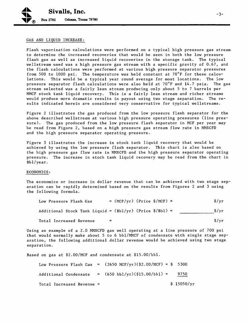
GAS AND LIQUID INCREASE:
Flash vapor izat ion calcu lat ions were per forned on a typ ica l h igh pressure gaa st reamto determine the increased recoverieg that nould be 6een in both the low pressuref lash gas as l re l l as increased l iqu id recover les i .n the storage tank. The typ ica ll reL ls t ream used was a h igh pressure gas st ream wi th a speci f ic grav i ty of 0 .67, andthe f lash celcuLat lons were per formed at var ious h igh pressure separator pressuresfron 500 to 1000 ps i . The tenperature was held constant at 70oF for these celcu-la t ions. This would be a typ lceL year round average for moet locat ions. The lowpressure separator f lash calcu lat ions were a lso held at 70"F and 14.7 ps ia. The gasstrean selected was a fa i r ly lean st ream producing only about 5 to 7 barre ls perMMCF stock tank liquid recovery. This is a fairly lean gtream and richer atreamawould produce more dramatic results in payout using tvo stage separation. The re-sul ts ind icated here in are considered very conservat ive for typ lcaL l reL ls t ream8.
Figure 2 i l lust rates the gas produced f ron the low pressure f lagh separator for theabove descr ibed wel ls t ream at var ioua h igh pressure operat ing pressures ( l ine pres-sure). The gas produced from the low pressure flash separator in MCF per year maybe read fron Figure 2, based on a high pressure gas stream flon rate in MMSCFDand the h igh pressure separator operat ing pressure,
Figure 3 il.lustrates the increase in stock tank liquid recovery that would beachieved by us ing the low pressure f lash sepsrator . This char t is a lso based onthe high pressure gas flow rate in MMSCFD and the high pressure separator operatingpressure. The increase in stock tank liquid recovery may be reed from the chart inBb 1/year .
ECONOMICS:
The economics or increese in doLLar revenue that can be achieved with two stege sep-arat ion ean be rapid ly determined based on the resul ts f rom Flgures 2 and 3 us ingthe following formula.
Tota l Inc reased Revenue
Us ing an example o f a 2 .0 MMSCFDthat wou ld normal ly make about 5a r a t i o n , t h e f o l l o w i n g a d d i t i o n a ls e p a r a t i o n .
$ /yr
$ / y t
$ /yr
g a s w e l l o p e r a t i n g a t a l i n e p r e s s u r e o f 7 0 0 p s it o 6 b b l / M M C F o f c o n d e n s a t e w i t h s i n g l e s t a g e s e p -
do l la r revenue wou ld be ach ieved us ing two s tage
Low Pressure Flash Gas = ( tqcr ' /yr ) (pr ice $/ucr ' )
A d d i t i o n a l S t o c k T a n k L i q u i d = ( g b 1 / y r ) ( p r i c e $ / B b 1 )
B a s e d o n g a s a t $ 2 . 0 0 / U C f a n d c o n d e n s a t e a t $ 1 5 . 0 0 / b b 1 .
L o w P r e s s u r e F l a s h G a s = Q | S O M C F / y r ) ( $ 2 . 0 O / t q c r ) = $
A d d i t i o n a l C o n d e n s a t e = ( 6 5 0 b b L / y r ) ( $ f S . 0 0 / b b 1 ) =
5300
9 7 5 0
Tota l Inc reased Revenue = $ t5050 /y r

^a\-4- \ \ Sivalls, Inc.
hx 2792 Odegsa, Texas 797ffi\ZO
SUM}IARY:
As can be seen from the above results the payout that could be achieved on the use
of t l r ro etage seperat ion is qul te dramat ic . The cost requi red for the addi t ion of a
enall low pressure flash eeparator to provlde for. t\ro stege separation is quite snalcompared to the additional recovery that could be achieved. This additional recover
not only produces dollsrs of revenue, but prevents the unneeded waate of precious
hydrocarbon energy that wouLd normally be vented out the stock tank using only singl
s tage aeparat ion.

-5-
!rRs:FcB-rl
E3!3
lrrc
BFH E* Et H-l
iP tE 6 *$ d s
Q eH H 3
F*Fu =t
al{\{-fkr=
gFe5Ec)t(t
t"F3,'E6
tl-
= p
E 6x i
\- t-k i E
l F b $t v ,
oE UF f ;E S
i-

- 6 -
FIGURE 2
LOW PRESSURE GAS FROMFLASH SEPARATOR
L'**i '-- il r'lirti*.'=lif,,i*ll-,''f i; i,l',
SIVALLS INC.6 /. / zt c.R.s.
GAS FLOW RATE - MMSCFD


TEIS PAGE BI...AIIK

^J\\ \
Sivalls, Inc.bx 2792 Odessa, Texas 797ffi\ZO
January 1, 1987 SECTION: 300TECHNICAL BULLETINNo. L62 , Rev. 1
FILTER SEPAMTORS
GENEML:
Filter Separators are combinatlon units which incorporate the features of a dryges f i l ter rd i th f iL ter e lements in conjunct ion wi th the feetures of a l iqu id-gasseparation unit. They are used primarily ahead of processing equipment where it isdesi rable to remove any sol id fore ign par t ic le e lements ae wel l as l iqu id f ronthe gas strearn, They would find application ahead of conpressors, dry desicantproceasing equipment, and gaa processing equipnent where contamination of a liquidc l rcu lated in the system would be undesi rable,
PROCESS DESCRIPTION:
FiL ter separa tors , nhether cons t ruc ted in a hor izon ta l o r ver t i ca l con f igura t ion ,are bas icaL ly two s tege vesse ls . The f l rs t s tage is an area wh lch is f i l l ed w i thmul t ip le sock type f i l te r e lenents fo r remov ing fo re ign so l ld par t i c le contami -na t ion f rom the gas a t ream. The f i l te r e lements a lso a id in coa lesc lng very smaL lpar t i c les o f l iqu id in to la rger d rop le ts , where they w i l l d ra in by grav i ty in to thel iqu id ee t t l - lng sec t ion o f the veeee l . The gas f low is f rom the ou ts ide o f thef i l te r e lements to the ins ide , and th rough a per fo ra ted mandr i l loca ted ins ide eache lement to the nex t s tage o f the vesse l . The in l .e t aec t ion a lso ac ts as a s lug ca t -cher for receiving surges of l iquid where it nay be trapped and passed into thel iqu id se t t l ing sec t ion o f the vesse l .
The second s tage o f the vesse l cons is ts o f an open separa tor sec t ion nh ich conta insa mist elininator for removlng smal1 entrained droplets from the gae stream beforei t passes ou t o f the vesse l . Th is n is t e l im ina tor may be e i ther a vane type con-f igura t ion or a s ta lnLess w i re nesh type.
The l iqu id separa ted f rom the gas in e i ther the f i rs t e tage or second s tage o f thevesse l pesses to a l iqu id se t t l ing sec t ion where i t i s d ischarged f rom the vesse l .
IIORIZONTAL FILTER SEPAMTORS :
F igure 5 i l - lus t ra tes a typ ica l hor izon ta l f i l te r separa tor wh ich is norau l l y con-s t ruc ted in a two-bar re l separa tor conf igura t ion . The gas passes th rough theupper bar re l o r tube o f the vesse l . The gas en ters th rough the in le t connect ionon the top o f the vesse l . and passes th rough the f i rs t s tage or f i l te r e lementsec t ion . On the end o f th is sec t ion ls a qu lck open ing c losure fo r ma in tenancethrough a smal l . se t t l ing sec t ion , and then th rough a mis t e l im ina tor be fore d is -charg ing f rom the vesse l a t the oppos i te end. The lower bar re l o r tube o f thesepara tor i s the l iqu id accuDula tor o r ee t t l ing sec t ion wh ich has dra in -back p ipesconnect ing the var ious por t ions o f the upper bar re l o f the vesse l . The l iqu idse t t l ing sec t ion is d iv i i led in to two compar tments so tha t there is no gas bypass

^J\- 2 - \ \
\ZO
Sivalls, Inc.Bo:r2792 Odesga,Texas 797ffi
t h r o u g h t h i s s e c t i o n f r o m t h e f i r s t s t a g e o f t h e v e s s e l t o t h e s e c o n d s t a g e .
E a c h c o m p a r t m e n t i n t h e l i q u i d s e t t l i n g s e c t i o n i s e q u i p p e d w i t h a h i g h p r e s s u r e
l i q u i d l e v e 1 c o n t r o l a n d d i a p h r a g m o p e r a t e d m o t o r v a l v e t o d i s c h a r g e t h e l i q u i d
a c c u m u l a t e d f r o m t h e v e s s e l . T a b l e 3 l i s t s t h e t y p i c a l s p e c i f i c a t i o n o f h o r i z o n -t a 1 h i g h p r e s s u r e f i l t e r s e p a r a t o r s .
VERTICAL FILTER SEPAMTORS :
Ver t i ca l F i l te r Separa tors a re i l l us t ra ted in F igure 6 and are normal ly cons t ruc tedin a s ing le vesse l con f igura t ion . The upper sec t ion o f the vesse l i s the f i rs ts tage o f the un i t wh ich houses the f i l te r e lenents . The top o f the vesse l i sequipped with a quick opening closure for renoval and changing of the fi l tere lements . The gas in le t i s on the s ide o f the f i rs t s tage o f the un i t and the gaspasaes in and th rough the f i l te r e lements sec t ion . A f te r pass ing th rough the f i l -ter elements the gas flow passes dotdnward into the lower stage or second stage ofthe vesse l , wh ich houses a se t t l ing sec t ion and the mis t e l im ina tor . The gas passes
through this section out through the Eist eliminator and leaves the vessel througha gas ou t le t connect ion on the lower s ide o f the vesse l . The upper s tage o f thevesse l i s equ ipped w i th a l iqu id leve l con t ro l and l iqu id d ischarge motor va lve tod ischarge any l iqu id accumula ted in th is por t ion o f the un i t . The lower s tage o fthe vesse l i s a lso equ ipped w i th a l iqu id leve l con t ro l and d iaphragm motor va lveto d ischarge l iqu id separa ted in the se t t l ing aec t ion and removed by the n is t e l im i -na tor . I t i s a lso necessary to have two l iqu id cont ro ls and two d ischarge motorva lves in th is type o f vesse l to p revent any bypass ing o f gas around the f i l te re lementa or mis t e l im ina tor . Tab le 4 l i s ts the typ ica l spec i f i ca t ions o f ver -t i ca l h igh preasure f i l te r separa tors .
FILTER SEPARATOR SIZING I
The gas capac i ty o f f i l te r separa tors may be de termined f rom the rap id s i -z t r .gchar ts conta ined in F igures 1 th rough 4 . The gas capac i ty o f smal1 hor izon ta lf i l t e r s e p a r a t o r s a r e s h o w n i n F i g u r e 1 . T h e l a r g e r m o d e l s a r e i l l u s t r a t e d i n
F i g u r e 2 . T h e g a s c a p a c i t y o f s m a l 1 v e r t i c a l f i l t e r s e p a r a t o r s a r e s h o w n i nF i g u r e 3 a n d t h e l a r g e r o n e s i n F i g u r e 4 . T h e s e g a s c a p a c i t i e s a r e b a s e d o n ag a s s p e c i f i c g r a v i t y o f 0 . 6 8 a n d a n o p e r a t i n g t e m p e r a t u r e o f 6 0 " F . F o r d i f -f e r e n t o p e r a t i n g c o n d i t i o n s , u s e t h e c o r r e c t i o n f a c t o r s c o n t a i n e d i n T a b l e s 1a n d 2 w i t h t h e f o l l o w i n g e q u a t i o n .
Q f = Q s x C g x C r
W h e r e t Q f = G a s c a p a c i t y a t o p e r a t i n g c o n d i t i o n s ' M M S C F D
Q s = G a s c a p a c i t y o f F i l t e r / S e p a r a t o r a t o p e r a t i n g p r e s s u r e
f rom char ts , MMSCFDC g = S p e c i f i c g r a v i t y c o r r e c t i o n f a c t o rC t = T e m p e r a t u r e c o r r e c t i o n f a c t o r

^'\ Sivalls, Inc.\ \ N
\ZO Box 2792 Odessa, Texas 797ffi
- 3 -
TABLE 1SPECIFIC GRAVITY CORRECTION FACTORS
IABLE 2TEMPERATURE CORRECTION FACTORS
Gas Temperaturecr
C o r r e c t i o n F a c t o r
5 0 " F6 07 0809 0
1001 1 0L20130
1 . 0 11 . 0 00 . 9 90 . g g0 . 9 70 . 9 60 . 9 5 50 . 9 50 . 9 4
CONCLUS ION :
The gas and l iqu id capac i t ies o f e i ther hor izon taL or ver t i ca l h igh pressuref i l t e r s e p a r a t o r s w i l l d i f f e r f r o m t h o s e o f c o n v e n t i o n a l o i 1 - g a s s e p a r a t o r s .Caut ion shou ld be observed in the des ign o f e i ther type o f vesse l to p rov ideone w i th the proper capac i ty tha t i s requ i red .
Ga sS p e c i f i c G r a v i t y
cgCorrec t ion Fac tor
0 . 5 50 . 6 00 . 6 50 . 6 80 . 7 00 , 7 50 . 8 00 . 8 50 . 9 0
1 . 1 11 . 0 6r . 0 21 . 0 00 . 9 80 . 9 50 . 9 30 . 8 90 . 8 7
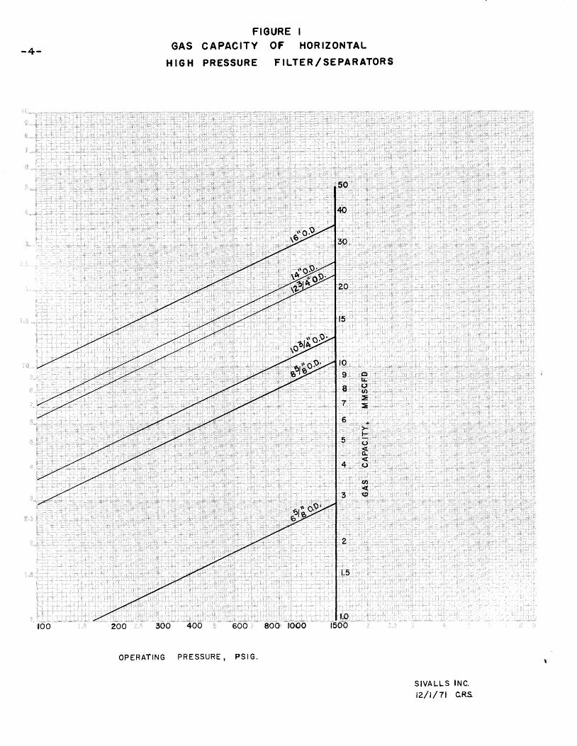
- 4 -
FIGURE IG A S C A P A C I T Y O F H O R I Z O N T A L
H I G H P R E S S U R E F I L T E R / S E P A R A T O R S
r#\?j
,"tlPciP to.....
r.9.. : l :: $-, i
: 6 ,:. :. ',t
, i
,5
6.,tl:lJ.wt;8.. . :. :>*r,p+uL
(t. :ii.{(t
e$o.ej
300 400 600
S I V A L L S I N C .
t2 / t / 7 l cRs
too
o P E R A T T N G P R E S S U R E , P S I G .
1500

F I G U R E 2G A S C A P A C I T Y O F H O R I Z O N T A L
HIGH PRESSURE F ILTER/SEPARATORS
- 5 -
rr
$
tl
6D
$o-o: l , ' 1 ,
700,.
i , . -
:6oo::.,,: ::,
l ' rr .- l :r l
5
, - , l l
400: . 1
, I
. , : ,
i ' . 1
, , ,so-0
l-0,-o'e0: : . '8-.0
,70-r : l
60' t ' : t t : '
5O,r ' l r i ' l : '
. . :'4a,,. : .. :30
%! ' rD
- ' . o9 '
h b 7
'oiP
;,eadP
*,6q
o,tJ-()A.:,E=i
: ' f>,rF:t),(L4(},: :
w(t
$: . r t '
$-
zoo 300 400 800., tooo
S I V A L L S I N C .
t2/ | /7t c.R.s.
O P E R A T I N G P R E S S U R E , P S I G
t500

-6 -
ir
FIGURE 3G A S C A P A C I T Y O F V E R T I C A L
H IGH PRESSURE Fr LTE R /SEPARATORS
z€JP
ids�
\6.JP
irffi
,dP
rco 400 $6;l'1666
dH(lr$,ItF,-E''.i't . i F
P-r"H&).,4.L-.lsl$r':- t :
6:rI
loiej
:8
.7j
i$lt"$;'i'
4
S I V A L L S I N C .t2 / t /7 t c .R.s ,
O P E R A T I N G P R E S S U R E , P S I G

F I G U R E 4G A S C A P A C I T Y O F V E R T I C A L
HIGH PRESSURE F ILTER / ,SCPARATORS
[oP 300
6qi\
6PAl , r l
ab
'otP
a6x{,Pfl,(J,:{t}"EE.' ' i>nl
6:ff.:{.4,.
;l J ' ,
IOppp9999.Q
,,9o..8. O.' . l l : '
'7'Q;,
, 6 0
4 0
vo9
}P
Px9
200 300
S I V A L L S I N G .t ? / t / 7 t c . R . s .
t00
OPERAT I NG PRESSURE , PS lG .
800., lo.oo
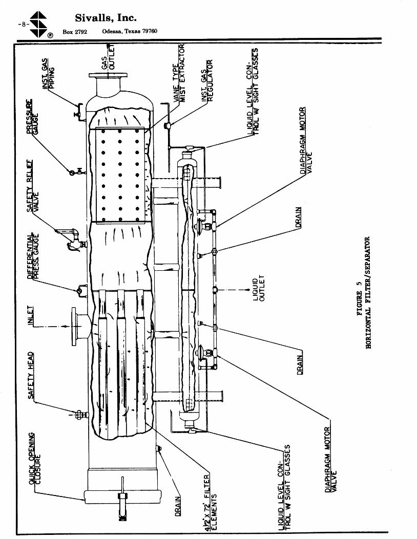
^a\- 8 - \ \
\ZO
Sivalls, Inc.hx 2792 Odesea, Texas 797ffi
r \ l \ \
c o c
o a o
o c o
c c o
c c a
c c c
c c o
t t \ \ \
t l t l
&ot4F.trlu,
, o f fE{
Fl ;f& H} f t rc,H C
F.zoNH&otrl
F9 q- r J
._ < f t1fv -
J O
5lq=lg
gH

^'\ Sivalls, Inc.\ \ \\ZO Box 2792 Odeeaa, Texas 797ffi
- 9 -
FIGURE 6VERTICAL FILTER SEPAMTOR
O U I C K O P E N I N GCLOSURE
SAFETY HEADS A F E T Y R E L I E FVALVE
4 Y?' x 72' FTLTERELEM EN TS
T N L E T _ € DIAPHRAGM MOTORVALVE
LIQUIDLEVEL CON-TROL SIGHTGLASS LIOUID OUTLET
DIFFERENTIALINST C 'AS PIPING PRESSURE GAUSE
GAS OUTLETVANE TYPE MISTEXTRACTOR
PRESSURE GAUGE
INST. GAS REG.
DIAPHRAGM MOTORVALVE
LIOUID LEVEL CON-TROL v STGHTGL ASSE S loutD 3u IlE T_
\-==+,= -"'
) _ ) _ lo o
o o l l .
o o
o o
o c l -
o o l -
l j
c
ELEVAT ION
DRAI N

^'\ Sivalls, Inc.- 1 0 - \ \
\ZO Box 2792 Odessa, Texas 797ffi
TABLE 3HORIZONTAL HIGH PRESSURE FILTER/ SEPARATORS
SPECIFICATIONS
TABLE 4VERTICAL HIGH PRESSURE FILTER/SEPAMTORS
SPECIFICATIONS
f. iast two digits of nodel number would change for different working pressure units.2. Other working pressures available are 23O, 500, 1200, 1440 psig.3. Gas capacity is at design working pressure for 0.69sP gr natural gas at 50"F.
l"1ode1N o . I
Upper TubeS ize
0D x LengthNomlnal
I . I . P . 2 p s i
Lower TubeS ize
OD x LengthInlet & Outlet
Gas Conn.std . o i lValves
Nomlnal .eas C.p""rtv3
MMSCFD
HES-610-10r{ES-810-10HES-1010-10HES-1210-10HES-1410-10HES-1610-10HES-181 2-L0HES-2012-10HES-2414-10HES-3016-10HES-3616-10HES-4218-10HES-4818-10HES-5420-10HES-6020-10
6-5 /8 " x 108-5 /8 " x 10 '
L0-3/4" x 10 't2-3/4" x 10I
L4" x 10|L 6 " x L O t18" x Lzl20" x L2l24" x L4l30" x 16 |36t ' x 16 t
42" x 18t48 t ' x 18 |
54" x 2Al60" x 201
1000 6 - 5 / 8 " x 7 '6 - 5 1 8 " x 7 l6 - 5 / 8 " x 7 '6 - 5 / 8 " x 7 l6 -5 /9 " x 7 ' �6 - 5 / 8 " x 7 l8 - 5 / 8 " x I '8 - 5 / 8 " x 8 l
L0-3/ 4" x 9 'L0 -3 /4 " x 11 'L0 -3 /4 " x lL '
l -4 t t x Lz lL4" x Lzl1 6 " x 1 3 rL 8 " x 1 3 t
2 "2 "3 t t
4tt
4 "4 "6 t t
6 t tg t t
1 0 t t
L2"L4"L 6 t t
L g t t
20"
l t t
l t t
l t t
l t t
l- tt
1 t t
l t t
1'lL t t
l t t
1 t t
1 t '
l_ tt
2 r t
2"
2 . 49 . 7
1 0 . 81 9 . 02 L . 029.5384 772
L27L72265330450560
ModelN o . 1
S i z eO . D . x L e n g t h
NoninalW , P . 2 p s i
Inl-et & Outl-etGas Conn.
srd. o i lValve
NomlnalGas Capacity3
MMSCFD
vES-1010-10vES-1210-10vES-1410-10vES-1610-10vEs-181 2-L0vES- 20L2-L0vEs-2414-10vEs-3014-10vES-3614-10vEs-4216-10vES-4816-10vES-541_6-10vES-6010-10
10-3/4" x 10L2-3/4" x l -0 '
L4" x 10'16 " x 10 r1 8 t t x L z l20" x Lzl24" x L4l30" x L4l3 6 " x l . 4 l42" x 16t48" x l"6 t
5 4 " x 1 6 t60" x 16 |
1000 2 "2"3 t t
4"4 "6 t t
6 t tg t t
L 0 t t
L 0 t t
Lzt'1 4 t t
L 6 t t
l _ t tl t t
1 t t
l i t
l_ tt
l t t
L t t
l t t
l t t
L t t
l_ tt
2 t t
2 r t
5 . 08 . 5
1 1 . 51 5 . 5
222743639 3
L22150zLO255

^'\ Sivalls, Inc.\ \ \\ZO Box 2792 Odeesa, Texas 797ffi
January 1, t987 SECTION: 300TECHNICAL BULLETINN o . L 6 3 , R e v . 1
LOW TEMPEMTURE GAS SEPAMTION UNITS
GENERAL:
Low tempera ture gas eepara t ion equ ipnent i s spec i f i ca l l y des igned to inc rease therecovery o f l iqu id d is t i l l a te f ro rn h igh pressure gas condensate we l ls , over tha twhich could be expected by conventional aeparation methods. Each well streanmust be examined w i th regards to the ana lys is o f the s t ream compos i t ion , as we l l asopera t ing charac ter is t i cs o f the weL1, such as f low ing preasures and temperarures ,to determine if i t would be economically feaslble to instaLl a lou temperaEure gassepara t ion un i t . s iva l l s , rnc . low tempera ture gas separa t ion un i ts a re each cus tomdes igned to meet the spec i f i c we l l s t ream charac ter is t i c and opera t ing cond i t ions ,In look ing a t the feas ib i l i t y o f ins ta l l ing a low te rnpera ture gas separa t ion un i t ,the opera tor shou ld a lso cons ider the type o f l iqu id s to rage equ ipEent ava i lab le ,o r to be ine ta l led , as we l l as the t ranspor ta t ion cos ta o f the recovered l iqu idproduc t .
PROCESS APPI,ICATION:
It is well known that lowering the operating teuperature of a separator wil l increasethe l iquid recovery. When the pressure is reduced on a high pressure gas condensates t rean by use o f a p ressure reduc ing choke, there is a lso acconpany ing decrease inthe fluid temperature. This is rnhat is knovn a6 the JouLe-Thompaon or throttl inge f fec t , wh ich is an i r revera ib le ad iabat ic p rocess where the heet conten t o f the gasremains the saue across the choke, but the pressure and teFperature of the gass t rean is reduced. l
It is aleo well knovn that a reduction of gas stream temperature wil l bring aboutthe problenr of hydrate formation in the Lines and equipment. This occurrence and thehand l ing o f hydra tes and gas s t reama is d iscussed nore comple te ly in o ther techn ica lpub l i ca t ions .z rJ However r in b r ie f , the hydra tes are so l id par t i c les and maasesformed in gas s t rearns cons is t ing o f water and l iqu ld hydrocarbons . These hydra teswi l l fo rm a t spec i f i c cond i t ions o f tempera ture and pressure fo r each gas s t reamwhich is genera l l y above 32"F fo r most h igh pressure gaa a t reaus .
The low temperature effect is uaed to advantage in low temperature units to increasethe l iquid recovery. The lower the operating temperature of the separator, thehigher the l iquld recovery wil l be. I lowever, the naximum flowing pressure from thewell at a given flor^t rate and the transmission l ine pressure rri l1 indicate the maxi-num amount of pressure drop avaiLabLe across the choke. Enthalpy curves on natural-gas can be used to determine the tenperature drop that can be expected based on theava i lab le p ressure drop .4 In genera l , a t leas t 2500 to 3000 ps i p ressure drop shou ldbe availabl.e frorn wellhead flowing preaaure to pipeline presaure before a low temper-a tu re separa t ion un i t w i l l pay ou t in inc reased l iqu id recovery , The lowest opera t iBgtemperature reconmended for low temperature units is usually around -20"F. Carbons tee l embr i t t lement occur be low th is tempera ture and h igh a1 loy s tee ls fo r lowertempera tures are usua l ly no t economica l fo r most o i l f le ld ins ta l la t ions . Genera l l y ,lo rd tenpera ture separa t ion un i ts a re opera ted in the range o f 0 "F to 20ot r .
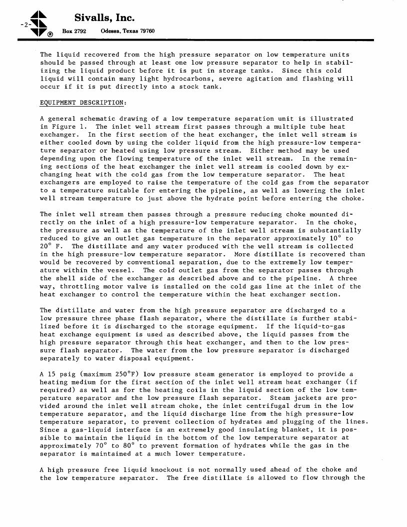
^J\-2 - \ \
\ZO
Sivalls, Inc.Box2792 Odessa,Texas 797ffi
The l iqu id recovered f rom the h igh pressure separa tor on low tempera ture un i tss h o u l d b e p a s s e d t h r o u g h a t l e a s t o n e l o w p r e s s u r e s e p a r a t o r t o h e l p i n s t a b i l -i -zLr .g the l iqu id p roduc t be fore i t i s pu t in s to rage tanks . S ince th is co ldl i q u i d w i l l c o n t a i n m a n y l i g h t h y d r o c a r b o n s , s e v e r e a g i t a t i o n a n d f l a s h i n g w i l lo c c u r i f i t i s p u t d i r e c t l y i n t o a s t o c k t a n k .
EQUIPMENT DESCRIPTION :
A genera l sche[a t ic d rawing o f a low teEpera ture separa t ion un i t i s i l l us t ra tedin F igure 1 . The in le t we l l s t ream f i rs t passes th rough a mul t ip le tube heatexchanger . In the f i rs t aec t ion o f the heat exchanger , the in le t we l l s t ream ise i ther coo led down by us ing the co lder l iqu id f ron the h igh pressure- low tempera-ture separator or heated using 1.ow pressure stream. Either method rnay be useddepending upon the fl.owing temperature of the inlet well strean, In the remain-ing sec t ions o f the heat exchanger the in le t we l l s t ream is coo led down by ex-changing heat nith the cold gas from the Lon temperature separator, The heatexchangers are ernployed to raise the temperature of the coLd gas from the separatorto a tempera ture su i tab le fo r en ter ing the p ipe l ine , as we l l as lower ing the in le twell atream temperature to just above the hydrate point before entering the choke,
The inlet well stream then passes through a pressure reducing choke mounted di-rec t l y on the in le t o f a h igh pressure- low te [pera ture separa tor . In the choke,the pressure as we l l as the tempera ture o f the in le t we l l s t ream is subs tan t ia l l yreduced to give an outlet gaa teEperature in the separator approximately 10o to20 ' F . The d is t i l l a te and any water p roduced w i th the we l l s t rearn is co l lec tedin the h igh pressure- low tempera ture separa tor . More d is t i l l a te i s recovered thanwould be recovered by conventional separation, due to the extremely low temper-a tu re w i th in the vesse l , The co ld ou t le t gas f rom the separa tor passes th roughthe 6he11 s ide o f the exchanger as descr ibed above and to the p ipe l ine . A th reeway, th ro t t l ing motor va lve is ins taL led on the coLd gas l ine a t the in le t o f theheat exchanger to control the temperature within the heat exchanger section.
The d is t i l l a te and water f ro ro the h igh pressure separa tor a re d ischarged to alow pressure th ree phase f lash separa tor r where the d is t i l . la te i s fu r ther s tab i -l i zed be fore i t i s d ischarged to the s to rage equ ipnent , I f the l iqu id - to -gasheat exchange equ ipment i s used as descr ibed above, the l iqu id passes f rom thehigh pressure separator through this heat exchanger, and then to the low pres-sure f lash separa tor . The na ter f rom the low pressure separa tor i s d ischargedsepara te ly to water d isposa l equ ipEent .
A 15 psig (maximum 250'F) low pressure steam generator is employed to provide aheat ing ned ium fo r the f i rs t sec t ion o f the in le t ! ,7eL1 s t ream heat exchanger ( i f
requ i red) as we l l as fo r the heat ing co i l s in the l iqu id sec t ion o f the lov tem-pera ture separa tor and the low pressure f lash separa tor . S team jackets a re p ro-vided around the inlet lrell stream choke, the inlet centrifugal drum in the lowtempera ture separa tor , and the l iqu id d ischarge l ine f ron the h igh pressure- lowtempera ture separa tor , to p revent co l lec t ion o f hydra tes and p lugg ing o f the l ines .S ince a gas- l iqu id in te r face i . s an ex t remely good insu la t ing b lanket , i t i s poe-
sible to maintain the l iquid in the bottom of the low temperature separator atapproximately 70o to 80" to prevent fornation of hydrates while the gas in theseDara tor i s ma in ta ined a t a much lower temDera ture .
A high pressure free l iquid knockout is not normally used ahead of the choke andthe low tempera ture separa tor . The f ree d is t i l l a te i s a l lowed to f low th rough the

^a\\ \
Sivalls, Inc.Box2792 Odeasa,Texas 797ffi
- 3 -
\ZO
choke along rrith the gae. Any free distil late and irater in the lnlet I'ell streamwill pass through the choke and remain essentlally at the same temperature as itentered. I t is conceded that th is f ree d ls t i l la te enter ing the separator wi lL g iveup some heat and slightLy raise the temperature of the gas rrithin the separator.Any free nater accompanying the gas and distilLate through the choke will act inthe sane rulnner. llorrever, accordlng to flagh vaporization calculations and fieldtests , the f ree d is t i l la te v i l l act as an absorpt ion o iL and ectuaLLy ebsorb moreof the gasoLine end the butane fraction from the htgh pressure gae stream. There-fore, nore distil late can be recovered et e higher operating temperature than lrouldbe possible at a lower opersting tempersture, if the distil late rrere renoved aheadof the choke and discharged into the separator separately. Free water will havea more adverse effect upon the gaa temperature lrithln the Beparator, since it haga h igher speci f ic heat than the d is t i l la te, General ly , the nater has to be pro-duced. in quantitles of at least 10 barrels per IIMCF, before the heat given up byrtater to the gas in the Beparator rriLl raiae the gas temperature enough to cauaeany adverse af fects upon the d is t iL la te recovery. I f th is were the case, the.n afluid packed freewater knockout ahead of the separator and choke would be recom-mended. This is shorrn on a schematic drarring ea an optlonel lten. However, thegas and free dlstil late from the fLuid knockout would pass directly through thechoke and into the aeparator as described above to obtain the absorptlon cheracter-ig t ics of the f ree dts t i l la te.
The process for low temperature separation bes been thoroughly investigated witltrespect to l iqu id recovery by both f lssh calcu lat ions and f ie ld tests . S ivaLls ,Inc. is convinced that it has merit over other processea that are now availableon the market. Sivalle low temperature aeparation unita are able to operate athigh tenperatures (10" to 20"F in the low temperature separator rather than0-10"F) which will give the operator lese operational problens while naintaininghtgh d is t i l la te recover les.
ESTIMATED RICOVERIES:
A recovery chart is il lustrated ln Figure 2 by which it is possible to determinethe effect of the lower separation temperature on Llquld recovery. This will aesistln feasibility studies to determine if lorrr teEperature separation equipnent rril lpay out olr a given well stream. The purpose of this chsrt ls to estinate theliquid recovery by a 1o!, temperature eeparation unit, knowing the liquid recoveryor gas/oil ratio that can be obtained by conventional separation unita.
As i l lust rated by the dot ted 1 ine8 on the char t , f i r8 t locate a point o f in ter-section of known GOR or barrels per MMCF recovery, end the tempereture at whichthe conventional separation test waa made. Fo1low parallel to the slanting Linegfrom thls point to the intersection of the proposed low temperature separatortemperature. Read vertically fron thls corner to determlne the predicted distil laterecovery in barrels per MMCF or the GOR. In the exerple eholrn, tf lt ls knolrtn that20 barrele per MMCF can be recovered at a separatlon tempereture of 80oF, thenapproximately 25.7 barre\e per MMCF can be recovered at a separatLon temperature of20"F. On most Slva l ls , Inc. low temperature separat ion uni ts i t rsould be possib l€to maintain the sarne recovery at a separation temperature of 10"F higher or approxt-nate ly 30oF.
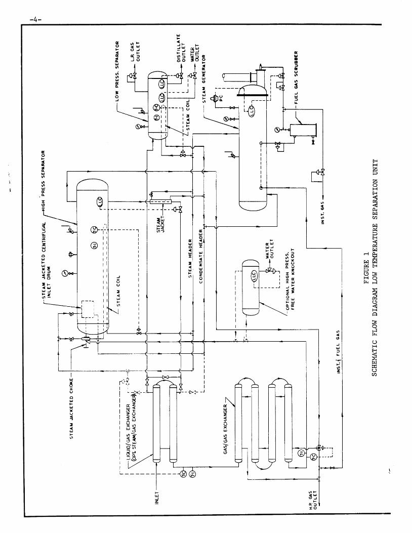
-4-
3' ,-J '''i c( t',{- - u r JF : F I - F
3 t lE
( , / l ) F< l !( ) J
i 5co
c6trJo./iolr,co]oJ
cblooDcuvl
t,|
(9
UJlItI
g
o
clrJ2lr,0
-u,
o
I
FHzpzoHH
E
tutqa
fEl&H
#F1
r l AE
E I ] r cd H( J BF { oh F l
tflC)
HABoFlh
CJHtr{gtrl
L)a
(/|(,JUJ
t!
|.:ll
=
ul
(D
F.vr
=
E lr,v JF F< f' o
Io
aflrJ.trtt(nu,Ic
-9
s&zrJ,JUolr,
U .u l< g? o
t F< lrJU J Jl - ? !
a<rUJC2zI()xt|'la(9
t{uJFaFro.\:,
IJ-
''J-Il rl L
III
l c. tr,
i zt <i It ( J, xl l !Il a; <t o| \
r f
IlrJ
I(,oUJFlr.II
?
:l!
F
o
Fu,)z
: ; oi i r[ 3
zt l9 cl u J
- <i '9 u rF tt,o . GO E
I
r l-t-;r lt l
q ll l
1 l1 l, lt l
r lr lt lr l
l lt ll gt tl rI '
rdl J l\,
@r---\ t / |I
,4, I\e/ |I
I
I
I
I
I
I
I
T - - ' j I
. t l lt l
J r lL r - ' - - i I
r l l
Gtr,o
LirlrJ
ozIJoz
CltJoujt
I
t!F
- - - - - - - - " 1
J
C)
=r.!l-(,
| . / )F< r r Jg J
Fo: fI O
:
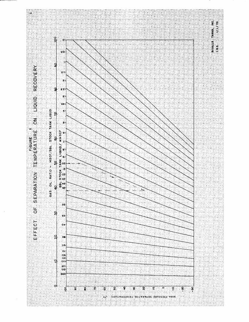
iri:rl: t , : , : ;
:jl-rl i: i i : . ' :
,i i.,
;..i;rr:,j:'.
r:,i ii.,*;"
; €i i i '
ic
.9,!
t 1
g l
' . t l
,61
ai
,i i l::r.. .l
?zc?,E
li;iii':{t)
=
ci.-;5.gtJi. r::x4€H:
Y()o.tl,.ttr"to ltg-'
,,oiOi.eCtlosj
ooc
? , , ? r , $
9,,.v .:g;:
)I:t
:s.z ;t -l , :
! c lL } ,o :t-'i !n
i ':q :E .
lr" :( ) , l(rr*l
,1,;;,Ii,;o :li''.-<&r,l : : ; :
.Jrro ,
.qt:€(0:'
rft' ' ' ' -j
. ' b J '0 f I
'lrl ,D' . i5 F ,$ , { 'trffi
, & , r 'E r
.1,.;ilj,;',,r ' r t , , . . .Hr,. , i .
, : . : , : ' i :Z: i r :'-,i';.s,tt'i ' ' t ' t :F , ,
{; . 8: . {. . O . , 'l: l i .rldt.;,, - : : , r l , f f ) t , ri , : r l ' : : : i : : : i' i . i , : l :
t : . : i , : i
: : .r : : t l l l j i l . , : ,
. , ,1 . . . : . ( l l : ,1
, : , ' : , ." , , . i , ,r ,] : i : rr lr ; : i :rr '1 r '1: i : : l
.-,,i ' i l$l..,t ; : i r r , . , '
: , r i : r r ld ' l .i:i lt tlir lll rl i : i: i
r r ; , , , , ; : : , , : , ,'t.i.i.;r
;:..r1::.::.:.il:-,lj.i::l ;:i l. tltrJ: :

^a\ Sivalls, Inc.-6 - \ \
\ZO Box TI92 Odeesa, Texas ?,97ffi
RXFERENCES
1. Katz , Dona ld L . , e t €11, r rHandbook o f Natura l Gas Eng ineer ing t t , McGraw-Hi l l ,
L 9 5 9 , p p 1 3 5 .
2 . S i v a l l s , C . R i c h a r d , t t l n d i r e c t H e a t e r s , D e s i g n a n d S i z i n g t t , T e c h n i c a l
B u l l e t i n N o . 1 1 3 , S i v a l l s , I n c .
3 . S iva1 ls , C . R ichard , t tG lyco l Dehydra t ion Des ign Manua l " , Gas Cond i t ion ing
Conference, Un ivers i ty o f Ok lahoma, L974.

a\t\ Sivalls, Inc.
hx TI92 Odesaa, Texas 797ffilZo
January 1 , 1987 S E C T I O N : 3 0 0TECHNICAL BULLETINN o . L 7 7
VERTICAL GAS SCRUBBERS
INTRODUCTION:
Where on ly smal l o r t race amounts o f f ree l iqu id a re known to be present in a gass t r e a m , v e r t i c a l g a s s c r u b b e r s m a y b e d e s i g n e d a n d s i z e d u s i n g t h e g a s c a p a c i t yo f t h e m i s t e l i m i n a t o r o n l y . T h i s w i l l r e s u l t i n a c o n s i d e r a b l y s m a l l e r v e s s e lf o r a g i v e n g a s f l o w r a t e . O r a g i v e n s i z e v e s s e l w i l l h a n d l e c o n s i d e r a b l y m o r eg a s t h a n i t w o u l d u n d e r c o n v e n t i o n a l v e r t i c a l s e p a r a t o r s i z i n g p r o c e d u r e s . T h ev e s s e l w o u l d b e e q u i p p e d w i t h a c o n v e n t i o n a l l i q u i d l e v e 1 c o n t r o l a n d l i q u i dd i s c h a r g e v a l v e , a n d , o f c o u r s e , w o u l d h a v e a s e t t l i n g s e c t i o n i n t h e b o t t o m o ft h e v e s s e l f o r a c c u m u l a t i n g l i q u i d d r a i n e d o u t o f t h e m i s t e l i m i n a t o r . H o w e v e r ,s u r g e r o o m w o u l d b e l i m i t e d a n d t h e r e w o u l d b e n o s e t t l i n g s e c t i o n f o r s e p a r a t i o no f t h e l i q u i d a n d g a s b y g r a v i t y .
T h e m a j o r f u n c t i o n o f t h e v e s s e l i s t o h o u s e t h e m i s t e l i m i n a t o r s e c t i o n w h i c hw o u l d r e m o v e e n t r a i n e d l i q u i d m i s t f r o m t h e g a s s t r e a m s t r i c t l y d u e t o t h e a c t i o no f t h e m i s t e l i m i n a t o r . T h i s t y p e o f v e s s e l m i g h t b e u s e d a h e a d o f c o m p r e s s o r swhere o ther separa t ion equ ipment has a l ready removed a l l o f the f ree l iqu ids r o rd o w n s t r e a m o f p r o c e s s v e s s e l s w h e r e o n l y e n t r a i n e d l i q u i d s o r s l i g h t a m o u n t s o fmis t car ry overs wou ld be expec ted in the gas s t ream.
CONSTRUCTION:
A ver t i ca l gas scrubber wou ld normal ly be cons t ruc ted ident ica l to a smal l twophase ver t i ca l gas separa tor . I t wou ld have a tangent ia l in le t d iver te r , a l iqu idleve l coa t ro l and d ischarge va lve , and fu l l d iameter w i re nesh mis t e l i r ina torin the top o f the vesse l , Other uaua l separa tor dev ices wou ld be fu rn ished suchas sa fe ty head, p ressure re l ie f va lve , leve l gauge, e t ce tera , Norna l l y , thesevesse ls wou ld be bu i l t in on ly a 5 ' to 7 -L /2 t he igh t , depend ing on the d iametero f the vesse l . These wou ld no t be equ ipped fo r th ree phase opera t ion , s incethere would be not enough surge room for a conventioneL settLing section in thebot toqr o f the vesse l fo r p roper separa t ion o f f ree water and d is t iLLate . SeeTab le 2 fo r typ ica l spec i f i ca t ions o f s tandard s ize ver t i ca l gas scrubbers .Norurally, the gas scrubbers roould have larger inlet and outlet gas connectionsthan wou ld convent iona l aepara tors o f the same phys ica l s ize , because thesevessels would be handling considerabLy more voluues of gas than would a conven-t iona l separa tor .
SCRUBBER DESIGN:
T h e g a s c a p a c i t y o f v e r t i c a l g a s s c r u b b e r s m a y b e c a l c u l a t e di n g e m p i r i c a l r e l a t i o n s h i p p r o p o s e d b y S o u d e r s - B r o w n . T h i su s e d f o r c o n v e n t i o n a l s e p a r a t o r s i z i n g w i t h o n l y a c h a n g e i nf a c t o r .
f rom the fo1 low-is the same equat ion
t h e e m p i r i c a l K
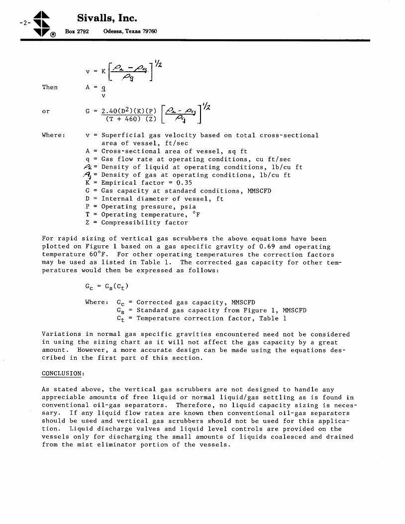
^a\-2- \\ Sivalls, fnc'
\ZO Box 2792 Odessa, Texas 797ffi
v = rl p--- p.r, l 'hL a x J
T h e n A = g
W h e r e : v = S u p e r f i c i a l g a s v e l o c i t y b a s e d o n t o t a l c r o s s - s e c t i o n a la r e a o f v e s s e l , f t / s e c
[ = C r o s s - s e c t i o n a l a r e a o f v e s s e l , s q f tq = G a s f l o w r a t e a t o p e r a t i n g c o n d i t i o n s , c u f t / s e c
P z = D e n s i t y o f l i q u i d a t o p e r a t i n g c o n d i t i o n s , l b / c u f t. 4 1 = D e n s i t y o f g a s a t o p e r a t i n g c o n d i t i o n s , l b / c u f tK " = E m p i r i c a l f a c t o r = 0 . 3 5G = G a s c a p a c i t y a t s t a n d a r d c o n d i t i o n s , M M S C F DD = I n t e r n a l d i a m e t e r o f v e s s e l , f tP = O p e r a t i n g p r e s s u r e , p s i aT = Opera t ing tempera ture , oF
Z = C o m p r e s s i b i l i t y f a c t o r
F o r r a p i d s i z i n g o f v e r t i c a l g a s s c r u b b e r s t h e a b o v e e q u a t i o n s h a v e b e e np l o t t e d o n F i g u r e 1 b a s e d o n a g a s s p e c i f i c g r a v i t y o f 0 . 6 9 a n d o p e r a t i n gt e m p e r a t u r e 6 0 " F . F o r o t h e r o p e r a t i n g t e m p e r a t u r e s t h e c o r r e c t i o n f a c t o r sm a y b e u s e d a s l i s t e d i n T a b l e 1 . T h e c o r r e c t e d g a s c a p a c i t y f o r o t h e r t e m -p e r a t u r e s w o u l d t h e n b e e x p r e s s e d a s f o l l o w s :
c c = G s ( c r )
W h e r e t G c = C o r r e c t e d g a s c a p a c i t y , M M S C F DGs = Standard gas capac i ty f rom F igure 1 , MMSCFDC t = T e m p e r a t u r e c o r r e c t i o n f a c t o r , T a b l e 1
V a r i a t i o n s i n n o r m a l g a s s p e c i f i c g r a v i t i e s e n c o u n t e r e d n e e d n o t b e c o n s i d e r e di n u s i n g t h e s i z i n g c h a r t a s i t w i l l n o t a f f e c t t h e g a s c a p a c i t y b y a g r e a tamount . However , a more accura te des ign can be made us ing the equat ions des-c r i b e d i n t h e f i r s t p a r t o f t h i s s e c t i o n .
CONCLUSION:
A s s t a t e d a b o v e , t h e v e r t i c a l g a s s c r u b b e r s a r e n o t d e s i g n e d t o h a n d l e a n ya p p r e c i a b l e a m o u n t s o f f r e e l i q u i d o r n o r m a l l i q u i d / g a s s e t t l i n g a s i s f o u n d i nc o n v e n t i o n a l o i l - g a s s e p a r a t o r s . T h e r e f o r e r D o l i q u i d c a p a c i t y s i z i n g i s n e c e s -s a r y . I f a n y l i q u i d f l o w r a t e s a r e k n o w n t h e n c o n v e n t i o n a l o i l - g a s s e p a r a t o r ss h o u l d b e u s e d a n d v e r t i c a l g a s s c r u b b e r s s h o u l d n o t b e u s e d f o r t h i s a p p l i c a -t i o n . L i q u i d d i s c h a r g e v a l v e s a n d l i q u i d 1 e v e l c o n t r o l s a r e p r o v i d e d o n t h ev e s s e l s o n l y f o r d i s c h a r g i n g t h e s m a l l a m o u n t s o f l i q u i d s c o a l e s c e d a n d d r a i n e df r o m t h e m i s t e l i m i n a t o r p o r t i o n o f t h e v e s s e l s .

^a\ Sivatls, Inc.\ \ \\ZO Box Tl92 Odesea, Texas 797ffi
- 3 -
TABLE 1TEI'IPERATURE CORRECTION FACTORS
FOR FIGURE 1
TABLE 2SPECIFICATIONS
VERTICAL GAS SCRUBBERS
*Other standard working pressures aval lable are 230, 500, 600, 1200, 1440, 2000Ps i g .
**Last two digi ts of model number would change for other working pressures, i .e.1440 ps i (14 ) , 500 ps i (6 ) .
Opera t ingTempera tu re , oF
Cor rec t ionF a c E o r , C t
4 050607 0809 0
1001101�20
1 . 0 41 . 0 21 . 0 00 . 9 80 . 9 60 . 9 50 . 9 30 . 9 10 . 9 0
I lode1N o . * *
S i z eo . D . ,i n .
She l lHe igh t
f r
WorkingP r e s s u r e ,
Ps ig*
GasConne c t ions
In le t &Out le t
S tandardLiquid\talve
Sh ipp ingWeigh t ,
I b .
vcs- 1 610vcs-2010vcs-2410vcs-3010vcs-36r0vcs-4210vGs-4810vcs-5410vcs-6010
16"20"24"3 0 t t
3 6 t t
42"4 g t t
54"60"
5 t5 t5 t5 t
7 - r / 2 l7 - t / 2 '7 - L / 2 '7 - L / 2 17 - r l 2 l
1000100 01 000100010001000100010001000
3 t t
4 t t
4 "6 t t
6 r tg t t
g t t
10"10"
l t t
l t t
1 t t
l t t
l t t
1 t t
l t t
l t t
L t '
1 2 0 017002600340056007900
10600r27 001 7 9 0 0

- 4 -
, ' , , FIGURE, l, ' " ,.ggS.: CAPACITY. V€RTICAL
: GAS' SCR'UB$f ft$' 1
200
600
srvALL s , tNc.c.R.s. '- 7/to/go
i ,
. I . , - , '
t200
GAS .-SP' GR. O.GAS, 'TEMP. 60
po908070
60
50
40
30
20
obro! s= 8
t ' 75 6f 5o 4
-":P6a:
dP
?lc;:
io;P
o. , 3
I800 I ooo
P S I G
r.o20�0 400
oPERAT|NG PR ESSUR E ,t400
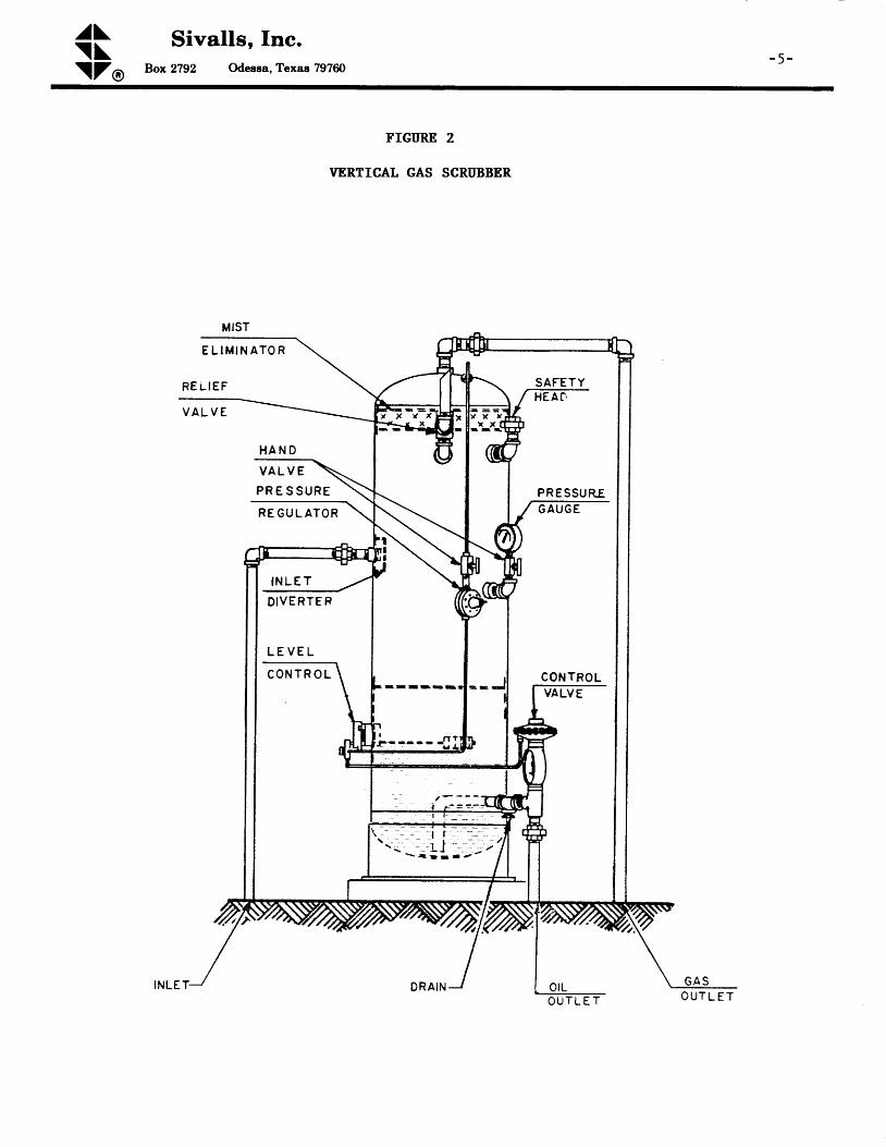
^a\\ \\ZO
Sivalls, Inc.Bo:r2792 Odessa,Texas 797ffi
- 5 -
FIGURE 2
VERTICAL GAS SCRUBBER
E L I M I N A T O R
R E r l E F
H A N D
V A L V E
PR E S SURE
R E G U L A T O R
MIST
SAFETYm'rr-
PRESSUREG A U G E
CONTROL
- - - - J T
I N L E T
D I V E R T E F
L E V E L
C O N T R O L
0rLO U T L E T O U T L E T