oildyne 108 series hydraulic power · pdf file108 series hydraulic power units pressures to...
TRANSCRIPT

108 Series Hydraulic Power UnitsPressures to 241 bar (3500 psi)Flows to 2.8 lpm (3/4 gpm)
3
Oildyne
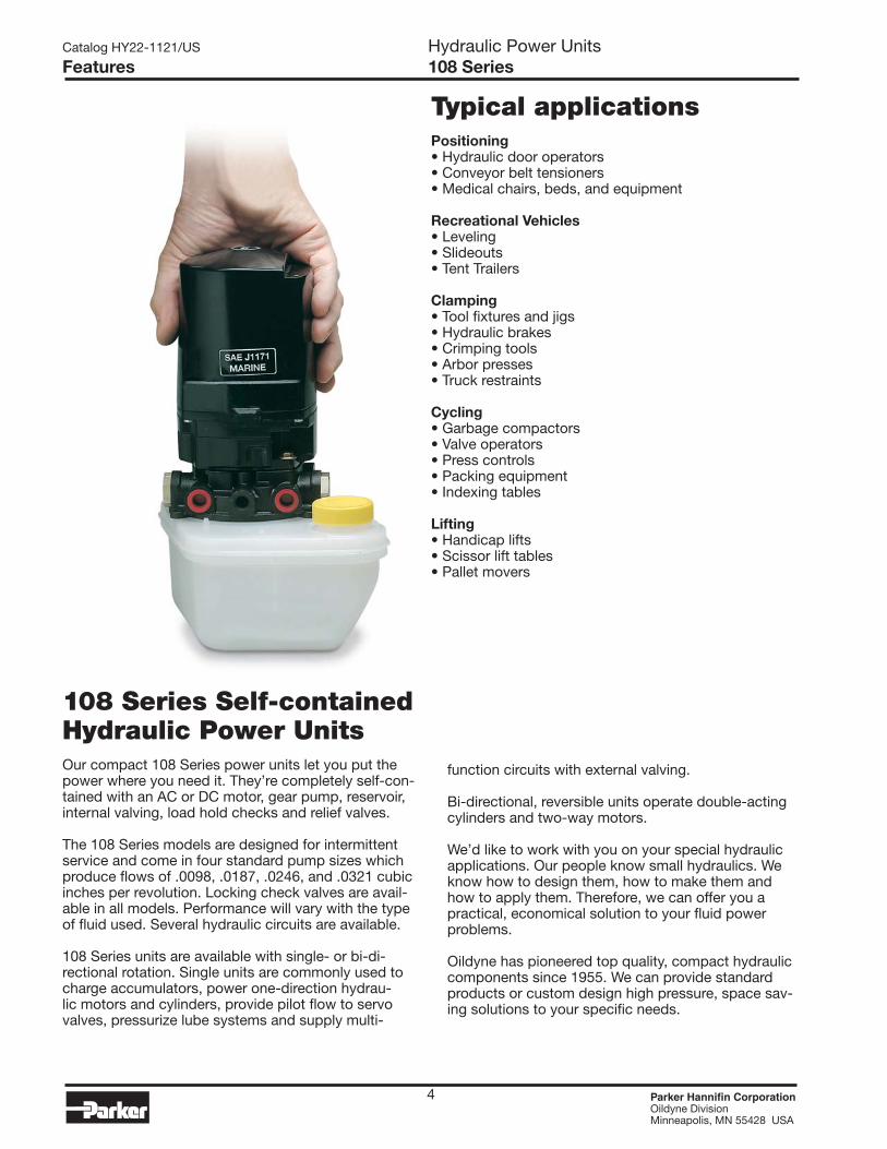
108 Series Self-containedHydraulic Power UnitsOur compact 108 Series power units let you put the power where you need it. They’re completely self-con-tained with an AC or DC motor, gear pump, reservoir, internal valving, load hold checks and relief valves.
The 108 Series models are designed for intermittent service and come in four standard pump sizes which produce flows of .0098, .0187, .0246, and .0321 cubic inches per revolution. Locking check valves are avail-able in all models. Performance will vary with the type of fluid used. Several hydraulic circuits are available.
108 Series units are available with single- or bi-di-rectional rotation. Single units are commonly used to charge accumulators, power one-direction hydrau-lic motors and cylinders, provide pilot flow to servo valves, pressurize lube systems and supply multi-
function circuits with external valving.
Bi-directional, reversible units operate double-acting cylinders and two-way motors.
We’d like to work with you on your special hydraulic applications. Our people know small hydraulics. We know how to design them, how to make them and how to apply them. Therefore, we can offer you a practical, economical solution to your fluid power problems.
Oildyne has pioneered top quality, compact hydraulic components since 1955. We can provide standard products or custom design high pressure, space sav-ing solutions to your specific needs.
Typical applicationsPositioning• Hydraulic door operators• Conveyor belt tensioners• Medical chairs, beds, and equipment
Recreational Vehicles• Leveling• Slideouts• Tent Trailers
Clamping• Tool fixtures and jigs• Hydraulic brakes• Crimping tools• Arbor presses• Truck restraints
Cycling• Garbage compactors• Valve operators• Press controls• Packing equipment• Indexing tables
Lifting• Handicap lifts• Scissor lift tables• Pallet movers
4
Catalog HY22-1121/US Hydraulic Power UnitsFeatures 108 Series
Parker Hannifin Corporation Oildyne DivisionMinneapolis, MN 55428 USA

5
Catalog HY22-1121/US Hydraulic Power UnitsTechnical Information 108 Series
Standard Product Ordering Code
MOTOR CODEAE 12 vdc Permanent MagnetAM 12 vdc Series WoundBE 24 vdc Permanent MagnetBI 24 vdc Series WoundHA 115 vac, 1 phase, OpenHD 230 vac, 1 phase, OpenIA 36 vdc Permanent Magnet
108
108 POWER UNIT- includes relief
valve(s)
PUMP TYPES StandardC Cold Temp
PUMP SIZE10 .0098 CIPR19 .0187 CIPR25 .0249 CIPR32 .0321 CIPR
RESERVOIRA 26 cu. in. (13 cu. in. usable)B 46 cu. in. (23 cu. in. usable)C 46 cu. in. (26 cu. in. usable)D Alternate orientation version of CF 122 cu. in. (82 cu. in. usable)G 69 cu. in. (46 cu. in. usable)H 1/2 gallon usableI 1 gallon usableJ 1-1/2 gallon usable
CIRCUIT TYPENN Single directionWW Single direction with checkRR ReversibleLL Reversible lockingRB Reversible with Back PressureLB Reversible locking with Back Pressure
Each Solenoid Valve option belowincludes the WW circuit:
S1 12 vdc, Normally ClosedS2 24 vdc, Normally ClosedS3 120 vac, Normally ClosedS4 240 vac, Normally ClosedS5 12 vdc, Normally OpenS6 24 vdc, Normally OpenS7 120 vac, Normally OpenS8 240 vac, Normally Open
PORTS1 7/16-20 (SAE -4)2 7/16-24 (Inv. Flare)3 1/8" Pipe (NPSF)4 1/8" Pipe (BSPP)
MOUNTINGV Vertical (motor up)H Horizontal
UP RV SETTING(Left Hand Port)In multiples of 100 psiExamples04 = 400 psi12 = 1200 psi29 = 2900 psi
DN RV SETTING(Right Hand Port)Use 00 for Single Dir.In multiples of 100 psiExamples04 = 400 psi12 = 1200 psi29 = 2900 psi
ORDERING CODE INSTRUCTIONSSelect the model code needed based on catalog information. All boxes above must be filled in before Oildyne can process theorder. If the power unit is a single direction unit use '00' for the DN (Right Hand) relief valve box.
ALL DATA SUBJECT TO CHANGE WITHOUT NOTICEFOR POWER UNIT CONFIGURATIONS OTHER THAN THOSE SHOWN PLEASE CONSULT OILDYNE.
P 1/4 gal. usable (plastic)Q 1/2 gal. usable (plastic)R 1 gal. usable (plastic)S 3/4 gal. usable (plastic)
NOTES: C and D reservoirsare available as VerticalMount ONLY. A reservoir withpump 32 is available ONLY asvertical mount.
Hydraulic FluidATF, OD18, or other clean hydraulic oil with a viscos-ity of 150 to 300 SUS at 38°C (100°F) is acceptable. If another type of fluid is needed, please consult the factory.
Temperature RangeNormal operating range is +20°F to +140°F. Please review your application with the factory for uses be-low -7°C and over +60°C (+20°F and over +140°F).
Parker Hannifin Corporation Oildyne DivisionMinneapolis, MN 55428 USA

6
12/24 V DC Permanent Magnet Motor • Code AE • BE
115/230 V AC Capacitor Start Motor • Code HA • HD
12/24 V DC Series Wound Motor • Code AM • BI
-24 VDC SUPPLY (BI)-12 VDC SUPPLY (AM)
MOTORTHERMAL BREAKER;BI MOTOR HAS 50 AMPTHERMAL BREAKER.
NOTES: AM MOTOR HAS 100 AMP
MOTOR LEAD BLUE
CONTACTSSOL 1 SWITCH
MOTOR LEAD BLACK
MOTOR LEAD GREEN
CONTACTSSOL 2 SWITCH
PORTLEFT HAND
SWITCH SOL
+24 VDC SUPPLY (BI)+12 VDC SUPPLY (AM)
PORTRIGHT HAND
SWITCH SOL1 2
TOGGLE SWITCH CENTER OFF SPDT
Catalog HY22-1121/US Hydraulic Power UnitsTechnical Information 108 Series
207(3000)
172(2500)
0
5
10
15
20
25
Current - A
mps
Current@ 12 VDC
Flow
Current@ 24 VDC
Pressure - bar (psi)
0 34(500)
138(2000)
103(1500)
69(1000)
Out
put F
low
- lp
m (c
ipm
)
.100 Pump (.0098 cipr) with AE / BE Motor
0
.16
.33
.49
.66
.82
(40)
(30)
(20)
(10)
(50)
241(3500)
207(3000)
172(2500)
0
12
24
36
48
60
Current - A
mps
Current@ 12 VDC
Flow
Current@ 24 VDC
Pressure - bar (psi)
0 34(500)
138(2000)
103(1500)
69(1000)
Out
put F
low
- lp
m (c
ipm
)
.100 Pump (.0098 cipr) with AM / BI Motor
0
.33
.66
.98
1.3
1.6
(80)
(60)
(40)
(20)
(100)
207(3000)
172(2500)
0
1
2
3
4
5
Current - A
mps
Current@ 115 VAC
Flow
Current@ 230 VAC
Pressure - bar (psi)
0 34(500)
138(2000)
103(1500)
69(1000)
Out
put F
low
- lp
m (c
ipm
)
.100 Pump (.0098 cipr) with HA / HD Motor
0
.16
.33
.49
.66
.82
(40)
(30)
(20)
(10)
(50)
MOTOR
MOTOR
RED AND BLACK LEADSTO REVERSE, INTERCHANGE
CONNECTION230 VOLTAGE
CONNECTION115 VOLTAGE
L-1YELLOW3 AMP
GREEN/YELLOW
REDORANGE
BLUE
WHITEBLACK
RELAY
161-193 MFD/230V
4
L-2
2 3
WHITE
GREEN/YELLOWRED
ORANGEYELLOW
BLACK
BLUEL-2
161-193 MFD/125V
7 AMPL-1
RELAY2
4
3BROWN
BROWN
+24 VDC SUPPLY (BE)+12 VDC SUPPLY (AE)
-24 VDC SUPPLY (BE)-12 VDC SUPPLY (AE)
SWITCH USABLE UP TO 20 AMPS@ 12 VDC
DPDT CENTER OFF TOGGLE
MOTOR
MOTOR LEAD
BLUE ORBLACK
PORTRIGHT HAND
MOTOR LEAD
GREEN OR ORANGE
PORTLEFT HAND
OFF TOGGLE SWITCH DPDT CENTER
Wiring Diagram: AE • BE
Wiring Diagram: AM • BI
Wiring Diagram: HA
Note: 50 hz performance is 83% of curves shown.
Wiring Diagram: HD
Motor Type: HA and HD Dual voltage 1/3 HP, 60/50 hz, 3450/2850 rpm, intermittent duty, single phase, open frame. Capacitor and relay included.
Motor Type: AM and BI For intermittent duty cycles.
Motor Type: AE and BE For intermittent duty cycles.
Parker Hannifin Corporation Oildyne DivisionMinneapolis, MN 55428 USA

7
Catalog HY22-1121/US Hydraulic Power UnitsTechnical Information 108 Series
.327 Pump (.0321 cipr) with AE / BE Motor
0
10
20
30
40
50
Current - A
mps
Current@ 12 VDCFlow
Current@ 24 VDC
Pressure - bar (psi)
0 34(500)
138(2000)
103(1500)
69(1000)
Out
put F
low
- lp
m (c
ipm
)
0
.49
2.0(120)
1.5(90)
.98(60)
(30)
2.5(150)
207(3000)
172(2500)
0
10
20
30
40
50
Current - A
mps
Current@ 12 VDC
Flow
Current@ 24 VDC
Pressure - bar (psi)
0 34(500)
138(2000)
103(1500)
69(1000)
Out
put F
low
- lp
m (c
ipm
)
.250 Pump (.0246 cipr) with AE / BE Motor
0
.33
.66
.98
1.3
1.6
(80)
(60)
(40)
(20)
(100)
241(3500)
207(3000)
172(2500)
0
15
30
45
60
75
Current - A
mps
Current@ 12 VDC
Flow
Current@ 24 VDC
Pressure - bar (psi)
0 34(500)
138(2000)
103(1500)
69(1000)
Out
put F
low
- lp
m (c
ipm
)
.190 Pump (.0187 cipr) with AM / BI Motor
0
.49
.98
1.5
2.5
2.0(120)
(90)
(60)
(30)
(150)
207(3000)
172(2500)
0
20
40
60
80
100
Current - A
mps
Current@ 12 VDC
Flow
Current@ 24 VDC
Pressure - bar (psi)
0 34(500)
138(2000)
103(1500)
69(1000)
Out
put F
low
- lp
m (c
ipm
)
.250 Pump (.0246 cipr) with AM / BI Motor
0
.66
1.3
2.0
3.3
2.6(160)
(120)
(80)
(40)
(200)
172(2500)
0
20
40
60
80
100
Current - A
mps
Current@ 12 VDC
Flow
Current@ 24 VDC
Pressure - bar (psi)
0 34(500)
138(2000)
103(1500)
69(1000)
Out
put F
low
- lp
m (c
ipm
)
.327 Pump (.0321 cipr) with AM / BI Motor
0
.82
1.6
2.5
4.1
3.3(200)
(150)
(100)
(50)
(250)
207(3000)
172(2500)
0
2
4
6
8
10
Current - A
mpsCurrent
@ 115 VAC
Flow
Current@ 230 VAC
Pressure - bar (psi)
0 34(500)
138(2000)
103(1500)
69(1000)
Out
put F
low
- lp
m (c
ipm
)
.190 Pump (.0187 cipr) with HA / HD Motor
0
.33
.66
.98
1.3
1.6
(80)
(60)
(40)
(20)
(100)
207(3000)
172(2500)
0
2
4
6
8
10
Current - A
mps
Current@ 115 VAC
Flow
Current@ 230 VAC
Pressure - bar (psi)
0 34(500)
138(2000)
103(1500)
69(1000)
Out
put F
low
- lp
m (c
ipm
)
.250 Pump (.0246 cipr) with HA / HD Motor
0
.33
.66
.98
1.3
1.6
(80)
(60)
(40)
(20)
(100)
21 41 62 83 103 124(300) (1800)(1500)(1200)(900)(600)
1
2
3
4
5
6
Current - A
mps
Current@ 115 VAC
Flow
Current@ 230 VAC
Pressure - bar (psi)
0
Out
put F
low
- lp
m (c
ipm
)
.327 Pump (.0321 cipr) with HA / HD Motor
0
.41
.82
1.3
1.6
2.0
(100)
(75)
(50)
(25)
(125)
207(3000)
172(2500)
0
10
20
30
40
50
Current - A
mps
Current@ 12 VDC
Flow
Current@ 24 VDC
Pressure - bar (psi)
0 34(500)
138(2000)
103(1500)
69(1000)
Out
put F
low
- lp
m (c
ipm
)
.190 Pump (.0187 cipr) with AE / BE Motor
0
.25
.49
.74
.98
1.2
(60)
(45)
(30)
(15)
(75)
Note: Performance data is for reference only.
Performance data based on ATF @ 21°C ( 70°F)
Parker Hannifin Corporation Oildyne DivisionMinneapolis, MN 55428 USA

8
“S*” CIRCUIT
RV
TRV
UP
“WW” CIRCUIT
RV
TRV
UP DN
“NN” CIRCUIT
RV
UP DN
Thermal Relief Valves—Why?The thermal relief valve’s (TRV) purpose is to allow a bleed off of built up pressure due to thermal expan-sion of the fluid or to act as a (limited) shock load pro-tection, should a cylinder in the system get bumped.
The thermal relief valve is included in circuits using a pilot operated check valve. The single direction units get one; the reversing units get two. It is located between the check valve and the 108 Series pump outlet port. It is a fixed relief valve with a pressure setting approximately 100-140 bar (1500-2000 psi) above the system relief valve pressure.
Catalog HY22-1121/US Hydraulic Power UnitsCircuits 108 Series
Parker Hannifin Corporation Oildyne DivisionMinneapolis, MN 55428 USA

9
Back Pressure Circuits—Why?The basic reversible circuit is essentially a closed loop. The oil returning from the system is fed back into the pump inlet. When a cylinder is being retracted more oil is being returned to the power unit than is leaving it due to the rod volume. This results in the DN side relief valve cracking open allowing the rod volume of oil to go back to the tank. The larger the rod volume the more open the relief valve will be. In many applications this is not a problem. However, if work is being done on the retract stroke, or if a pressure switch is used to signal the cylinder is fully retracted, the back pressure circuit is required. This circuit allows the rod volume of
oil to return to the reservoir through a special shuttle spool, before it reaches the pump. Full relief valve pressure is then available to retract the cylinder, also preventing a pressure switch from tripping before the full retract position is achieved.Recommended uses: • In systems where work is being done on the retract stroke • Where a pressure switch is used to signal the full retract position • In systems requiring a faster retract than extend speed
“LL” CIRCUIT
HPRV
TRV
UP
LPRV
TRV
DN
“LB” CIRCUIT
BACK PRESSURE CIRCUIT
HPRV LPRV
TRV
UP DN
TRV
BACK PRESSURE CIRCUIT
“RB” CIRCUIT
HPRV
UP
LPRV
DN
“RR” CIRCUIT
HPRV LPRV
UP DN
Catalog HY22-1121/US Hydraulic Power UnitsCircuits 108 Series
Parker Hannifin Corporation Oildyne DivisionMinneapolis, MN 55428 USA

10
(1.21)30.7
RESERVOIR46 CU IN
(3.36)85.3
(1.15)29.2
(1.15)29.2 (5.88)
149.4
(3.83)97.3
(1.16)29.4
(1.16)29.4
(2.55)64.9
B
A
C
(4.44)112.8
MIN MIN
LEFT SIDE (IN FRONT VIEW)WOULD HAVE FILLER CAP ONALTERNATE ORIENTATIONORIENTATION IS SHOWNSTANDARD RESERVOIR
PORT SIZE SEE CODING
MAX
FRONT VIEW
FILLER CAPRESERVOIR
MAX
SIDE VIEW
3/8-16 UNC-2B X 7/16 DP.2 MOUNTING HOLES
BACK VIEW
Overall Dimensions
Reservoir Dimensions
Catalog HY22-1121/US Hydraulic Power UnitsDimensions 108 Series
SOLENOID VALVE
UNUSED PRESSURE PORT PLUG
7/16-20 PRESSURE PORT
RESERVOIR FILLER CAP
29.2(1.15)
29.2(1.15) 141.7 1.5
(5.58 .06)
30.7(1.21)
126.2(4.97)
83.8 1.5(3.30 .06)
1.27 0.8(.05 .03)
75.4 0.8(Ø2.97 .03)
12 VDC MOTOR
Motor Dimensions ±.1.3 (±.050)
A B C
AE/BE 75.4 126.2 241.3 (2.97) (4.97) (9.50)
AM/BI 95.8 151.4 266.4 (3.77) (5.96) (10.49)
IA 75.4 128.8 244.1 (2.97) (5.07) (9.61)
HA/HD 100.1 161.0 276.4 (3.94) (6.34) (10.88)
(10.50)266.7
(Ø3.70)93.9
(4.88)123.8
(3.16)80.3
(Ø3.59)91.2
(3.36)85.3
(6.38)162.1
(5.88)149.4
(6.34)161.0
(Ø4.00)101.6
(Ø4.00)101.6
(Ø3.70)93.9
46 CU. IN. (23 CU. IN. USABLE) ALUMINUM(754 CC: 377 CC USABLE)
HIGH DENSITY POLYETHYLENE WITH UV ADDITIVE STD.(754 CC: 426 CC USABLE)
46 CU. IN. (26 CU. IN. USABLE)
122 CU. IN. (82 CU. IN. USABLE) STEEL(2000 CC: 1344 CC USABLE)
“C” RESERVOIR
"F" RESERVOIR
“B” RESERVOIR
2
HDP
E
8
“A” RESERVOIR28 CU. IN. (13 CU. IN. USABLE) ALUMINUM
(459 CC: 213 CC USABLE)
"G" RESERVOIR#3-69 CU. IN. (46 CU. IN. USABLE) EXTRUDED ALUMINUM
(1130 CC: 754 USABLE)
"H, I , J" RESERVOIR - STEEL
Note: All dimensions in mm (inches).
With Solenoid
Note: refer to page 17 for information on the P, Q, R and S reservoirs.
Parker Hannifin Corporation Oildyne DivisionMinneapolis, MN 55428 USA
(5.60)142.3(6-7/8)
175.3
(12.27)311.7
(7.27)184.6
(16.27)413.3
(2 Liter)1/2 GAL
H
(4 Liter)1.0 GAL
I
(5.6 Liter)1.5 GAL
J
H, I, J RESERVOIR STEEL

165 Series Hydraulic Power UnitsPressures to 241 bar (3500 psi)Flows to 5.4 lpm (1.4 gpm)
11
Oildyne

Catalog HY22-1121/US Hydraulic Power UnitsPower Unit Features 165 Series
We are pleased to introduce our new 165 Series power units. The 165 Series power units let you put more power where you need it. As big brother to our successful 108 Series, the 165 Series is completely self-contained with a DC motor, gear pump, reservoir, internal valving, load hold checks and relief valves.
The 165 Series units are designed for intermittent duty and are available in three standard pump sizes producing flows of .032, .050 and .065 cubic inches per revolution. The units are available for single or bi-directional application with a number of hydraulic circuit options similar to our 108 Series.
Single direction units are commonly used to charge accumulators, power single direction hydraulic motors and single acting cylinders, as well as multi- function circuits with external valving.
Bi-directional units are commonly used to operate double acting cylinders and reversible motors.
We look forward to working with you on your specific applications. As pioneers and specialists in the design and manufacture of high quality compact hydraulic systems, we are well qualified to offer practical and economical solutions to your fluid power problems.
Your local Parker sales representative will be pleased to provide further information.
Features• 1 hp, 12 vdc motor• 3 pump sizes• Variety of circuits• Many reservoir choices• 241 bar (3500 psi) capability• Soft seat load hold valves• Vertical and horizontal mounting
Typical Applications• Wheelchair lifts• Scissors lift tables• RV levelers• RV room slides• Cab tilts• Mobile sign lifts• Boat lifts• Pallet movers• Yours?
12 Parker Hannifin Corporation Oildyne DivisionMinneapolis, MN 55428 USA

Standard Product Ordering Code
Catalog HY22-1121/US Hydraulic Power UnitsTechnical Information 165 Series
RESERVOIRC 26 cu. in. usableD Altern. orient. CG 46 cu. in. usableH 1/2 gal. usable (metal)I 1 gal. usable (metal)J 1-1/2 gal. usable (metal)P 1/4 gal. usable (plastic)Q 1/2 gal. usable (plastic)R 1 gal. usable (plastic)S 3/4 gal. usable (plastic)
NOTE: C and D reservoirsare available as VerticalMount ONLY
MOTOR CODEAY 12 vdc, 1 hp Perm. Magnet
AY
165 POWER UNIT- includes relief valve(s)
PUMP TYPES StandardC Cold Temp
PUMP SIZE32 .032 CIPR50 .050 CIPR65 .065 CIPR
CIRCUIT TYPENN Single directionWW Single dir. with checkRR ReversibleLL Reversible lockingRB Reversible with Back Press.LB Rev. lock. with Back Press.
Each Solenoid Valve optionbelow includes the WW circuit:S1 12 vdc, Normally ClosedS2 24 vdc, Normally ClosedS5 12 vdc, Normally OpenS6 24 vdc, Normally Open
PORTS1 7/16-20 (SAE -4)4 1/8" Pipe (BSPP)
MOUNTINGV Vertical (motor up)H Horizontal
UP RV SETTING(Left Hand Port)In multiples of 100 psiExamples04 = 400 psi12 = 1200 psi29 = 2900 psi
DN RV SETTING(Right Hand Port)If Single Direction circuituse 00In multiples of 100 psiExamples04 = 400 psi12 = 1200 psi29 = 2900 psi
165
ALL DATA SUBJECT TO CHANGE WITHOUT NOTICEFOR POWER UNIT CONFIGURATIONS OTHER THAN THOSE SHOWN PLEASE CONSULT OILDYNE.
ORDERING CODE INSTRUCTIONSSelect the model code needed based on catalog information. All boxes above must be filled in before Oildyne can process theorder. If the power unit is a single direction unit use '00' for the DN (Right Hand) relief valve box.
Hydraulic FluidATF, OD18, or other clean hydraulic oil with a viscos-ity of 150 to 300 SUS at 38°C (100°F) is acceptable. If another type of fluid is needed, please consult the factory.
Temperature RangeNormal operating range is +20°F to +140°F. Please review your application with the factory for uses be-low -7°C and over +60°C (+20°F and over +140°F).
Parker Hannifin Corporation Oildyne DivisionMinneapolis, MN 55428 USA
13

“S*” CIRCUIT
RV
TRV
UP
“WW” CIRCUIT
RV
TRV
UP DN
“NN” CIRCUIT
RV
UP DN
Thermal Relief Valves—Why?The thermal relief valve’s (TRV) purpose is to allow a bleed off of built up pressure due to thermal expansion of the fluid or to act as a (limited) shock load protec-tion, should a cylinder in the system get bumped.
The thermal relief valve is included in circuits using a pilot operated check valve. The single direction units get one; the reversing units get two. It is located be-tween the check valve and the 165 Series pump outlet port. It is a fixed relief valve with a pressure setting approximately 100-140 bar (1500-2000 psi) above the system relief valve pressure.
Catalog HY22-1121/US Hydraulic Power UnitsCircuits 165 Series
14 Parker Hannifin Corporation Oildyne DivisionMinneapolis, MN 55428 USA

Back Pressure Circuits—Why?The basic reversible circuit is essentially a closed loop. The oil returning from the system is fed back into the pump inlet. When a cylinder is being retracted more oil is being returned to the power unit than is leaving it due to the rod volume. This results in the DN side relief valve cracking open allowing the rod volume of oil to go back to the tank. The larger the rod volume the more open the relief valve will be. In many applications this is not a problem. However, if work is being done on the retract stroke, or if a pressure switch is used to signal the cylinder is fully retracted, the back pressure circuit is required. This circuit allows the rod volume of
oil to return to the reservoir through a special shuttle spool, before it reaches the pump. Full relief valve pressure is then available to retract the cylinder, also preventing a pressure switch from tripping before the full retract position is achieved.Recommended uses: • In systems where work is being done on the retract stroke • Where a pressure switch is used to signal the full retract position • In systems requiring a faster retract than extend speed
“LL” CIRCUIT
HPRV
TRV
UP
LPRV
TRV
DN
“LB” CIRCUIT
BACK PRESSURE CIRCUIT
HPRV LPRV
TRV
UP DN
TRV
BACK PRESSURE CIRCUIT
“RB” CIRCUIT
HPRV
UP
LPRV
DN
“RR” CIRCUIT
HPRV LPRV
UP DN
Catalog HY22-1121/US Hydraulic Power UnitsCircuits 165 Series
15 Parker Hannifin Corporation Oildyne DivisionMinneapolis, MN 55428 USA
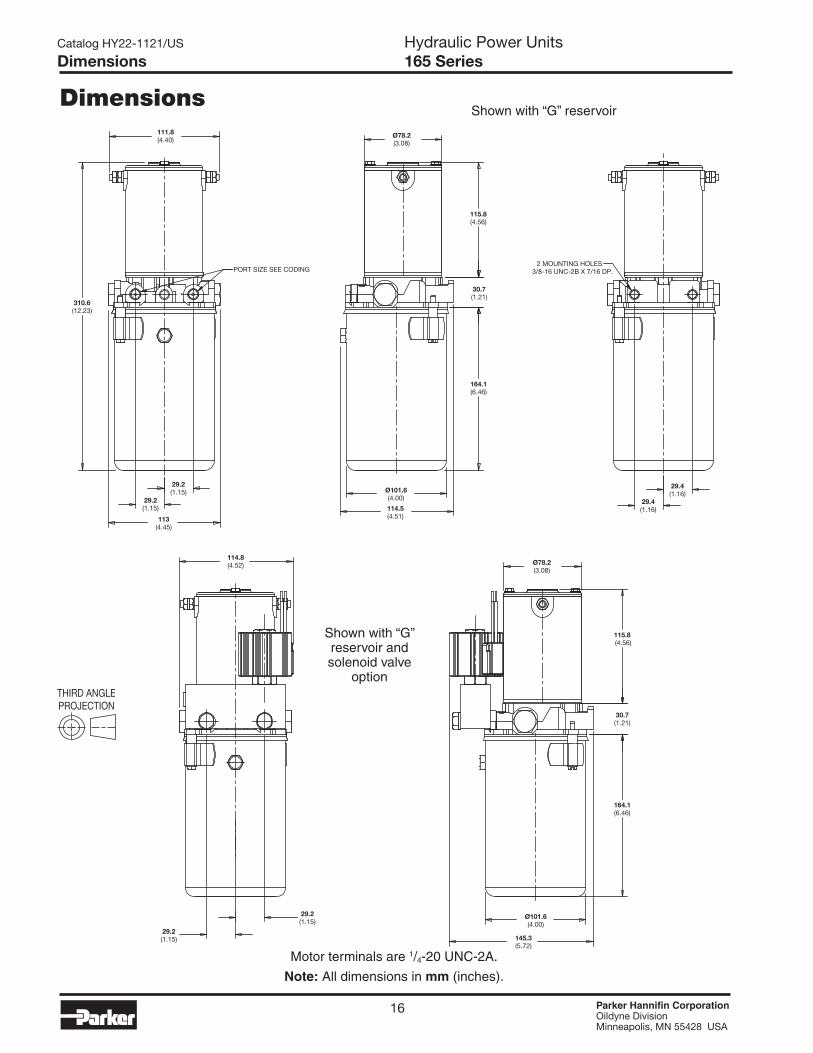
Dimensions
Catalog HY22-1121/US Hydraulic Power UnitsDimensions 165 Series
Motor terminals are 1/4-20 UNC-2A.
Note: All dimensions in mm (inches).
310.6(12.23)
Ø101.6(4.00)
Ø78.2(3.08)
111.8(4.40)
113(4.45)
29.2(1.15)
29.2(1.15)
115.8(4.56)
30.7(1.21)
164.1(6.46)
114.5(4.51)
29.4(1.16)
29.4(1.16)
PORT SIZE SEE CODING2 MOUNTING HOLES
3/8-16 UNC-2B X 7/16 DP.
Ø101.6(4.00)
Ø78.2(3.08)
29.2(1.15)
29.2(1.15)
115.8(4.56)
30.7(1.21)
164.1(6.46)
145.3(5.72)
114.8(4.52)
Shown with “G” reservoir
Shown with “G” reservoir and solenoid valve
option
16 Parker Hannifin Corporation Oildyne DivisionMinneapolis, MN 55428 USA

(5.60)142.3
(5.88)149.2
(6-7/8)175.3
(7.27)184.6
(16.27)413.3
(12.27)311.7
(2 Liter)
1/2 GAL
H
(4 Liter)
1.0 GAL
I
(5.6 Liter)
1.5 GAL
J
171.16.73( ) 152.4
6.00( )
112.54.43( )
143.55.65( )
2218.70( )
313.212.33( )
P Q S R1 QUART(1 LITER)
1/2 GALLON(2 LITER)
3 QUART(3 LITER)
1 GALLON(4 LITER)
403.915.90( )
Dimensions
Catalog HY22-1121/US Hydraulic Power UnitsDimensions 165 Series
Note: All dimensions in mm (inches).
Motor end view of above drawing
165 Series shown with steel reservoirs
165 Series shown with plastic reservoirs
17 Parker Hannifin Corporation Oildyne DivisionMinneapolis, MN 55428 USA

165 Series Performance
0
50
100
150
200
250
300
350
0 500 1000 1500 2000 2500 3000
Pressure - bar (psi)
Ou
tpu
t F
low
-lp
m (
cip
m)
25
0
50
75
100
125
150
175
Cu
rre
nt
- A
mp
s
650 Pump(.065 cipr)
327 Pump(.032 cipr)
500 Pump(.050 cipr)
0.82(50)
1.64(100)
2.46(150)
3.28(200)
4.10(250)
4.92(300)
5.74(350)
34(500)
69(1000)
103(1500)
138(2000)
172(2500)
207(3000)
241(3500)
Catalog HY22-1121/US Hydraulic Power UnitsPerfomance Data 165 Series
Note: Performance data is for reference only
Performance data based on ATF @ 21°C ( 70°F)
18 Parker Hannifin Corporation Oildyne DivisionMinneapolis, MN 55428 USA
CR-1
MOTOR
cdv 21- cdv 21+Toggle Switch
CR-2
CR-3
CR-4
Term. 2
CR-3
Term. 1 CR-2CR-1
CR-4
CR-1
MOTOR
cdv 21- cdv 21+ON/OFF Switch
Term. 2 Term. 1 CR-1
“AY” Wiring Diagram-Single Direction
“AY” Wiring Diagram-Reversible
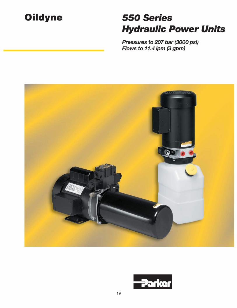
550 Series Hydraulic Power UnitsPressures to 207 bar (3000 psi)Flows to 11.4 lpm (3 gpm)
19
Oildyne
Catalog HY22-1121/US Hydraulic Power UnitsPower Unit Features 550 Series
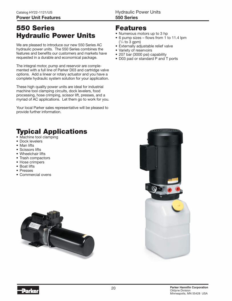
550 Series Hydraulic Power UnitsWe are pleased to introduce our new 550 Series AC hydraulic power units. The 550 Series combines the features and benefits our customers and markets have requested in a durable and economical package.
The integral motor, pump and reservoir are comple-mented with a full line of Parker D03 and cartridge valve options. Add a linear or rotary actuator and you have a complete hydraulic system solution for your application.
These high quality power units are ideal for industrial machine tool clamping circuits, dock levelers, food processing, hose crimping, scissor lift, presses, and a myriad of AC applications. Let them go to work for you.
Your local Parker sales representative will be pleased to provide further information.
Features• Numerous motors up to 3 hp• 6 pump sizes – flows from 1 to 11.4 lpm (1/4 to 3 gpm)• Externally adjustable relief valve• Variety of reservoirs• 207 bar (3000 psi) capability• D03 pad or standard P and T ports
Typical Applications• Machine tool clamping• Dock levelers• Man lifts• Scissors lifts• Wheelchair lifts• Trash compactors• Hose crimpers• Boat lifts• Presses• Commercial ovens
20 Parker Hannifin Corporation Oildyne DivisionMinneapolis, MN 55428 USA

550 Power Units @ 1725 RPM
17
14
20
07
04
10
(500) (3000)(2500)(2000)(1500)(1000)
(50)
(100)
(150)
(200)
(250)
(300)
(350)
0.8
1.6
2.5
3.3
4.1
4.9
5.7
(400)6.6
Out
put
Flo
w -
lpm
(cip
m)
0 34 69 103 138 172 207
Operating Pressure - bar (psi)
0
550 Power Units @ 3450 RPM
17
14
20
07
04
10
(500) (3000)(2500)(2000)(1500)(1000)
(100)
(200)
(300)
(400)
(500)
(600)
(700)
1.6
3.3
4.9
6.6
8.2
9.8
11.5
(800)13.1
Out
put
Flo
w -
lpm
(cip
m)
0 34 69 103 138 172 207
Operating Pressure - bar (psi)
0
Catalog HY22-1121/US Hydraulic Power UnitsPerformance Data 550 Series
Motor Horsepower Recommendations at Flow/Pressure Pump Nominal GPM Pressure (PSI) Size @1725 @3450 500 1000 1500 2000 2500 3000 04 .50 HP .50 HP .50 HP .50 HP .50 HP .50 HP 04 .50 HP .50 HP .50 HP .75 HP 1.0 HP 1.0 HP 07 .50 HP .50 HP .50 HP .75 HP 1.0 HP 1.0 HP 07 1 .50 HP .75 HP 1.0 HP 1.5 HP 2.0 HP 2.0 HP 10 .50 HP .50 HP .75 HP 1.0 HP 1.5 HP 1.5 HP 10 1 .50 HP 1.0 HP 1.5 HP 2.0 HP 3.0 HP 3.0 HP 14 1 .50 HP .75 HP 1.0 HP 1.5 HP 2.0 HP 2.0 HP 14 2 .75 HP 1.5 HP 2.0 HP 3.0 HP 17 1 .50 HP 1.0 HP 1.5 HP 2.0 HP 2.0 HP 17 2 1.0 HP 2.0 HP 3.0 HP 20 1 .50 HP 1.0 HP 1.5 HP 2.0 HP 20 3 1.0 HP 2.0 HP 3.0 HP
Performance data based on ATF @ 21°C ( 70°F)
Note: Performance data is for reference only
21 Parker Hannifin Corporation Oildyne DivisionMinneapolis, MN 55428 USA

Standard Product Ordering Code
Catalog HY22-1121/US Hydraulic Power UnitsTechnical Specifications 550 Series
550
MOTOR SELECTION - TEFCSingle Phase = 115/230 VAC, 60 HZThree Phase = 230/460 VAC, 60 HZCODE HP RPM PHASE TC .50 1725 Single TD .50 1725 Three TM .50 3450 Single TT .50 3450 Three TE .75 1725 Single TF .75 1725 Three TN .75 3450 Single TU .75 3450 Three TJ 1.0 1725 Single TK 1.0 1725 Three TP 1.0 3450 Single TW 1.0 3450 Three TL 1.5 1725 Single TO 1.5 1725 Three TQ 1.5 3450 Single TX 1.5 3450 Three TV 2.0 1725 Single TR 2.0 1725 Three TS 2.0 3450 Single TY 2.0 3450 Three TH 3.0 3450 Three
PUMP SIZECODE DISPLACEMENT 04 .04 CIPR 07 .07 CIPR 10 .10 CIPR 14 .14 CIPR 17 .17 CIPR 20 .20 CIPR
RESERVOIRCODE VOLUME 05 0.5 Gal. Steel 10 1.0 Gal. Steel 15 1.5 Gal. Steel 50 5.0 Gal. Steel 06 0.5 Gal. Plastic 11 1.0 Gal. Plastic 16 1.5 Gal. Plastic 26 2.5 Gal. Plastic
CIRCUITCODE DESCRIPTION D0 D03 Pad & Extension Fittings D1 D03 Pad with Dual PO Check Manifold (Manapak)
(for use with D03 Directional Control Valves) SA Standard Pressure & Tank Ports SW Std P & T Ports with Outlet Port Check Valve
Two Position Two Way Cartridge ValvesFollowing circuits include outlet port check valve:
S1 12 VDC, Normally Closed, Conduit Connector S2 24 VDC, Normally Closed, Conduit Connector S3 120 VAC, Normally Closed, Conduit Connector S4 240 VAC, Normally Closed, Conduit Connector S5 12 VDC, Normally Open, Conduit Connector S6 24 VDC, Normally Open, Conduit Connector S7 120 VAC, Normally Open, Conduit Connector S8 240 VAC, Normally Open, Conduit Connector
P1 12 VDC, Normally Closed, DIN Connector P2 24 VDC, Normally Closed, DIN Connector P3 120 VAC, Normally Closed, DIN Connector P4 240 VAC, Normally Closed, DIN Connector P5 12 VDC, Normally Open, DIN Connector P6 24 VDC, Normally Open, DIN Connector P7 120 VAC, Normally Open, DIN Connector P8 240 VAC, Normally Open, DIN Connector
550 POWER UNIT- includes relief valve
Note: 5 gal. steel reservoir can be mounted vertically only. All others are vertical and horizontal ready
22 Parker Hannifin Corporation Oildyne DivisionMinneapolis, MN 55428 USA

Catalog HY22-1121/US Hydraulic Power UnitsTechnical Specifications 550 Series
4-WAY VALVE (ALL D03 SIZE)CODE DESCRIPTION (For use only with Circuit Codes D0 and D1)NNN No 4-Way Valve Included01Y Closed Center, 120 VAC, Conduit Connectors01T Closed Center, 240 VAC, Conduit Connectors01K Closed Center, 12 VDC, Conduit Connectors01J Closed Center, 24 VDC, Conduit Connectors02Y Open Center, 120 VAC, Conduit Connectors02T Open Center, 240 VAC, Conduit Connectors02K Open Center, 12 VDC, Conduit Connectors02J Open Center, 24 VDC, Conduit Connectors07Y Float Center, 120 VAC, Conduit Connectors07T Float Center, 240 VAC, Conduit Connectors07K Float Center, 12 VDC, Conduit Connectors07J Float Center, 24 VDC, Conduit Connectors08Y Tandem Center, 120 VAC, Conduit Connectors08T Tandem Center, 240 VAC, Conduit Connectors08K Tandem Center, 12 VDC, Conduit Connectors08J Tandem Center, 24 VDC, Conduit Connectors30Y Single Solenoid, 120 VAC, Conduit Connector30T Single Solenoid, 240 VAC, Conduit Connector30K Single Solenoid, 12 VDC, Conduit Connector30J Single Solenoid, 24 VDC, Conduit Connector
Y01 Closed Center, 120 VAC, Hirschmann w/out PlugsT01 Closed Center, 240 VAC, Hirschmann w/out PlugsK01 Closed Center, 12 VDC, Hirschmann w/out PlugsJ01 Closed Center, 24 VDC, Hirschmann w/out PlugsY02 Open Center, 120 VAC, Hirschmann w/out PlugsT02 Open Center, 240 VAC, Hirschmann w/out PlugsK02 Open Center, 12 VDC, Hirschmann w/out PlugsJ02 Open Center, 24 VDC, Hirschmann w/out PlugsY07 Float Center, 120 VAC, Hirschmann w/out PlugsT07 Float Center, 240 VAC, Hirschmann w/out PlugsK07 Float Center, 12 VDC, Hirschmann w/out PlugsJ07 Float Center, 24 VDC, Hirschmann w/out PlugsY08 Tandem Center, 120 VAC, Hirschmann w/out PlugsT08 Tandem Center, 240 VAC, Hirschmann w/out PlugsK08 Tandem Center, 12 VDC, Hirschmann w/out PlugsJ08 Tandem Center, 24 VDC, Hirschmann w/out PlugsY30 Single Solenoid, 120 VAC, Hirschmann w/out PlugT30 Single Solenoid, 240 VAC, Hirschmann w/out PlugK30 Single Solenoid, 12 VDC, Hirschmann w/out PlugJ30 Single Solenoid, 24 VDC, Hirschmann w/out Plug
FLOW CONTROL(for use with Cartridge Valves)CODE DESCRIPTION NN None (use with D0 and D1 circuits) HP None (use with all other circuits) F1 Press. Comp., .5 to 1.0 GPM F2 Press. Comp., 1.0 to 2.0 GPM
RV SETTINGIn multiples of 100 psiExamples04 = 400 psi12 = 1200 psi29 = 2900 psi
Hydraulic FluidAny clean hydraulic oil with a viscosity of 150 to 300 SUS at 38°C (100°F) is acceptable. If another type of fluid is needed, please consult the factory.
Temperature RangeNormal operating range is -7°C to 60°C (+20°F to +140°F). Please consult the factory for applications outside this range.
23 Parker Hannifin Corporation Oildyne DivisionMinneapolis, MN 55428 USA

Catalog HY22-1121/US Hydraulic Power UnitsCircuits 550 Series
P T P T
P T P T
“SA” CIRCUIT “SW” CIRCUIT
“S1-S4, P1-P4” CIRCUITS “S5-S8, P5-P8” CIRCUITS
24 Parker Hannifin Corporation Oildyne DivisionMinneapolis, MN 55428 USA

P T
Catalog HY22-1121/US Hydraulic Power UnitsCircuits 550 Series
P T
A B
P T
A B
A B
P T
“S1-S4, P1-P4” CIRCUITS WITH PRESSURE COMPENSATED FLOW
CONTROL F1 OR F2
“S5-S8, P5-P8” CIRCUITS WITH PRESSURE COMPENSATED FLOW
CONTROL F1 OR F2
“D0” CIRCUIT (D03 VALVE TO BE SELECTED) “D1” CIRCUIT INCLUDES MANAPAK DUAL P0 CHECK VALVE (D03 VALVE TO BE SELECTED)
A B
P TCLOSED CENTER
A B
P TOPEN CENTER
A B
P T
A B
P T
FLOAT CENTER
TANDEM CENTER
A B
P TSINGLE SOLENOID
25 Parker Hannifin Corporation Oildyne DivisionMinneapolis, MN 55428 USA
1/2 GAL(2 liters)
191.87.55( )
1 GAL
251.59.90( )
1-1/2 GAL
311.112.25( )
2-1/2 GAL
430.516.95( )
24.10.95( )
24.10.95( )
158.96.25( )
134.6(5.30)
TP
9/16-18 UNF-2BSAE-6 STR THD O-RING PORTS
215.98.50( )
231.99.13( )
25.81.02( )
51.32.02( )
MOTOR HEIGHT237.2-299.7(9.34-11.80)
88.93.50( )
87.43.44( )
171.56.75( )
135.1(5.32)
SINGLE PHASEONLY
FILLER/BREATHER
101.6-169.1(4.00-6.50)
65.02.56( )
Ø182.1 MAX(7.17)
165.16.50( )
76.23.00( )
62.02.44( )
62.02.44( )
4X 8.6 (.34) SLOT
(4 liters)
(5.6 liters)
(9.5 liters)
Catalog HY22-1121/US Hydraulic Power UnitsDimensions 550 Series
Dimensions
Note: All dimensions in mm (inches).
550 Series shown with P and T ports and plastic reservoir
Motor foot dimensions are common to all 550 Series electric motors
Note: When mounted in the horizontal configuration the 21/2 gallon plastic reservoir must be supported
26 Parker Hannifin Corporation Oildyne DivisionMinneapolis, MN 55428 USA

Catalog HY22-1121/US Hydraulic Power UnitsDimensions 550 Series
177.8(7.00)
1/2 GAL(2 LITER)
134.6(5.30)
24.1(0.95)
TWO WAY VALVE(OPTIONAL)
LEADS 18GA609.6 (24.00) LONG
STRIPPED ENDS
9/16-18 UNF-2BSAE-6 STR THDO-RING PORTS
P T
304.8(12.00)1 GAL
(4 LITER)
406.4(16.00)
1-1/2 GAL(5.6 LITER)
101.3(3.99)
24.1(0.95)
140.4(5.53)
MOTOR HEIGHT237.2-299.7(9.34-11.80)
SINGLE PHASEONLY
FILLER/BREATHER
RELIEF VALVE
RETURN FLOW CONTROL(OPTIONAL)
135.1(5.32)
88.9(3.50)
25.8(1.02)
51.3(2.02)
98.0(3.86)
Note: All dimensions in mm (inches).
550 Series shown with optional solenoid 2-way valve and steel reservoirs
27 Parker Hannifin Corporation Oildyne DivisionMinneapolis, MN 55428 USA
Catalog HY22-1121/US Hydraulic Power UnitsDimensions 550 Series
550 Series shown with D03 valve, Manapak block and 5 gallon reservoir
Note: All dimensions in mm (inches).
28 Parker Hannifin Corporation Oildyne DivisionMinneapolis, MN 55428 USA
4X Ø
RESERVOIR MNT HOLES
9.5.38( )
387.415.25( )
36214.25( )
34.91.38( )
50.82.00( )
25.81.02( )
Ø171.56.75( )
598.823.58( )
311.312.26( )
51.32.02( )
131.85.19( )
63.62.51( )
58.62.31( )
231.69.12( )
66.82.63( ) 82.6
3.25( )
39.91.57( )93.5
3.68( )
215.98.50( )
1817.13( )
GAUGE PORT LOCATIONSAE-6 STR THD O-RING PORT
9/16-18 UNF-2B
2X 9/16-18 UNF-2AFLARE TUBE END
(OPTIONAL)
FILLER/BREATHER