service manual number 11 oildyne trim - · pdf fileservice manual number 11 oildyne trim pump...
TRANSCRIPT
5A
OILDYNE TRIM PUMPSERVICE MANUAL NUMBER 11
90-17431--4 MARCH 1998 Page 5A-1
POWER TRIMSection 5A - Oildyne Trim Pump
Table of Contents
Trim Pump Specifications 5A-2. . . . . . . . . . . . . . Valve Pressure Specifications 5A-2. . . . . . . . Electrical Specification 5A-2. . . . . . . . . . . . . . Torque Specification 5A-2. . . . . . . . . . . . . . . . Special Tools 5A-2. . . . . . . . . . . . . . . . . . . . . . . Lubricants/Adhesives/Sealers 5A-2. . . . . . . .
Trim Pump Exploded View 5A-3. . . . . . . . . . . . . . Oildyne Trim Pump 5A-3. . . . . . . . . . . . . . . . .
Maintaining Power Trim Pump Oil Level 5A-4. . Air Bleeding Power Trim System 5A-5. . . . . . . .
Bleeding OUT/UP Trim Circuit 5A-5. . . . . . . . Bleeding IN/DOWN Trim Circuit 5A-6. . . . . .
Testing Power Trim Pump 5A-7. . . . . . . . . . . . . . Test Gauge 5A-7. . . . . . . . . . . . . . . . . . . . . . . . Internal Restriction Test 5A-8. . . . . . . . . . . . . OUT/UP Pressure Test 5A-8. . . . . . . . . . . . . . IN/DOWN Pressure Test 5A-10. . . . . . . . . . . . Trim Pump Hydraulic System 5A-11. . . . . . . .
Trim Cylinder Internal Leak Test 5A-12. . . . . . . . Trim Cylinder Shock Piston Test 5A-14. . . . .
Motor and Electrical Bench Tests 5A-15. . . . . . . Trim Pump Motor Test (In Boat) 5A-15. . . . . Trim Pump Motor Test (Out of Boat) 5A-16. . Solenoid Test (Pump In Boat) 5A-17. . . . . . . Solenoid Test (Pump Out of Boat) 5A-18. . . . 110 Amp Fuse Test (Pump in Boat) 5A-20. . 110 Amp Fuse Test (Pump Out of Boat) 5A-21. . . . . . . . . . . . . . . . 20 Amp Fuse Test 5A-21. . . . . . . . . . . . . . . . .
Trim Pump Removal 5A-22. . . . . . . . . . . . . . . . . .
Hydraulic Repair 5A-23. . . . . . . . . . . . . . . . . . . . . Disassembly 5A-23. . . . . . . . . . . . . . . . . . . . . . Filter Replacement 5A-24. . . . . . . . . . . . . . . . . UP Pressure Relief Valve Replacement 5A-25. . . . . . . . . . . . . . . . . . . . . DOWN Pressure Relief Valve Replacement 5A-26. . . . . . . . . . . . . . . . . . . . . Thermal Relief Valve Replacement 5A-27. . . Pump Replacement 5A-28. . . . . . . . . . . . . . . . Adapter Replacement 5A-29. . . . . . . . . . . . . . Adapter Repair 5A-30. . . . . . . . . . . . . . . . . . . . Pump Shaft Oil Seal Replacement 5A-33. . .
Motor Repair 5A-35. . . . . . . . . . . . . . . . . . . . . . . . Disassembly 5A-35. . . . . . . . . . . . . . . . . . . . . .
Armature Tests 5A-38. . . . . . . . . . . . . . . . . . . . . . . Continuity Test 5A-38. . . . . . . . . . . . . . . . . . . . Test for Shorts 5A-39. . . . . . . . . . . . . . . . . . . . Cleaning Commutator 5A-39. . . . . . . . . . . . . .
Field Tests 5A-39. . . . . . . . . . . . . . . . . . . . . . . . . . Test for Open Circuit 5A-39. . . . . . . . . . . . . . . Test for Short in Field 5A-40. . . . . . . . . . . . . . Thermal Switch Continuity Test 5A-41. . . . . . Brush Replacement 5A-42. . . . . . . . . . . . . . . .
Reassembly 5A-44. . . . . . . . . . . . . . . . . . . . . . . . . Trim Pump Installation 5A-50. . . . . . . . . . . . . . . . Trim Pump Wiring Diagrams 5A-51. . . . . . . . . . .
Model With Three-Button Trim/Trailer Panel 5A-51. . . . . . . . . . . . . . . . . . . . . . . . . . . . Model With Trim In Handle and Trailer Switch Separate 5A-52. . . . . . . . . . . . . . . . . .

OILDYNE TRIM PUMP SERVICE MANUAL NUMBER 11
90-17431--4 MARCH 1998Page 5A-2
Trim Pump Specifications
Valve Pressure Specifications
PRESSUREVALVE
PSI kPa
Up Circuit 2200-2600 15173-17932
Down Circuit 400-600 2759-4138
Electrical Specification
PRESSUREPUMP AMPERAGE DRAW
PSI kPa
115 Amps at: 2200-2600 15173-17932
Torque Specification
TORQUEDESCRIPTION
lb. in. lb. ft. N·m
Up Pressure Relief Valve 70 7.9
Down Pressure Relief Valve 70 7.9
Thermal Relief Valve 70 7.9
Pump-to-Adaptor Mounting Screws 70 7.9
Motor-to-Adaptor Mounting Screws 25 2.8
Hex Plug Retainers 38-50 51-67
UP Pressure Hydraulic Hose (Black) 110 12
DOWN Pressure Hydraulic Hose(Gray)
110 12
Special Tools
DESCRIPTION PART NUMBER
Trim Pump Test Gauge Kit 91-52915A6
Torque Wrench (lb. in.) 91-66274
Lubricants/Adhesives/Sealers
DESCRIPTION PART NUMBER
Quicksilver Power Trim and Steering Fluid 92-90100A1
Quicksilver 2-4-C Marine Lubricant withTeflon
92-825407A12
Liquid Neoprene 92-25711-2
OILDYNE TRIM PUMPSERVICE MANUAL NUMBER 11
90-17431--4 MARCH 1998 Page 5A-3
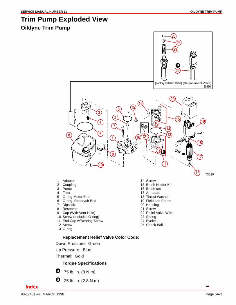
Trim Pump Exploded ViewOildyne Trim Pump
73519
���������� ���������������� (Replacement Valve)
a
b
�
�
�
�
�
�
�
�
�
�� ��
��
��
��
��
����
��
��
��
��
��
��
��
��
��
��
��
��
1 - Adaptor2 - Coupling3 - Pump4 - Filter5 - O-ring-Motor End6 - O-ring, Reservoir End7 - Dipstick8 - Reservoir9 - Cap (With Vent Hole)10- Screw (Includes O-ring)11- End Cap w/Bearing Screw12- Screw13- O-ring
14- Screw15- Brush Holder Kit16- Brush set17- Armature18- Thrust Washer19- Field and Frame20- Housing21- Screw22- Relief Valve With:23- Spring24- Eyelet25- Check Ball
Replacement Relief Valve Color Code:Down Pressure: Green
Up Pressure: Blue
Thermal: Gold
Torque Specifications
a 75 lb. in. (8 N·m)
b 25 lb. in. (2.8 N·m)
OILDYNE TRIM PUMP SERVICE MANUAL NUMBER 11
90-17431--4 MARCH 1998Page 5A-4
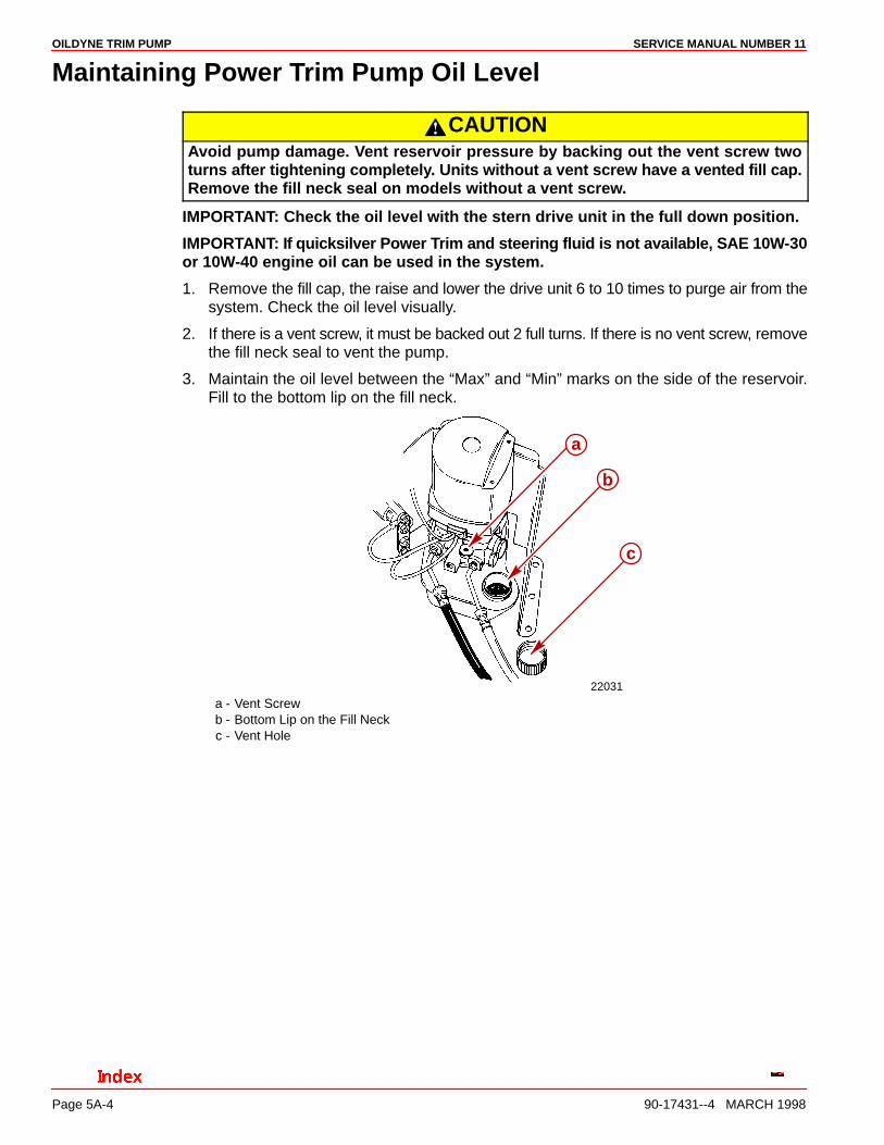
Maintaining Power Trim Pump Oil Level
CAUTIONAvoid pump damage. Vent reservoir pressure by backing out the vent screw twoturns after tightening completely. Units without a vent screw have a vented fill cap.Remove the fill neck seal on models without a vent screw.
IMPORTANT: Check the oil level with the stern drive unit in the full down position.
IMPORTANT: If quicksilver Power Trim and steering fluid is not available, SAE 10W-30or 10W-40 engine oil can be used in the system.
1. Remove the fill cap, the raise and lower the drive unit 6 to 10 times to purge air from thesystem. Check the oil level visually.
2. If there is a vent screw, it must be backed out 2 full turns. If there is no vent screw, removethe fill neck seal to vent the pump.
3. Maintain the oil level between the “Max” and “Min” marks on the side of the reservoir.Fill to the bottom lip on the fill neck.
22031
a
c
b
a - Vent Screwb - Bottom Lip on the Fill Neckc - Vent Hole

OILDYNE TRIM PUMPSERVICE MANUAL NUMBER 11
90-17431--4 MARCH 1998 Page 5A-5
Air Bleeding Power Trim System
1. The Power Trim System will purge itself of a small amount of air by raising and loweringthe drive unit several times. However, if a rebuilt trim cylinder is being installed (whichhas not been filled with oil), the following bleeding procedure should be used to removethe air from the system.
Bleeding OUT/UP Trim Circuit1. Fill the pump reservoir to the proper level as explained preceding. (The trim cylinder
must be compressed.)
2. Disconnect the OUT/UP hose from the front connection on the trim cylinder. If both cylin-ders were rebuilt, disconnect the hoses from both cylinders.
3. Direct the end of the trim hoses(s) into a container.
4. Run the trim pump in the UP direction until a solid, air-free stream of fluid is expelled fromthe hose(s). Reconnect the hose(s) and tighten securely.
5. Refill the trim pump to the proper level.
50389a
b
a - OUT/UP Trim Hoseb - Front Connection On Trim Cylinder
OILDYNE TRIM PUMP SERVICE MANUAL NUMBER 11
90-17431--4 MARCH 1998Page 5A-6
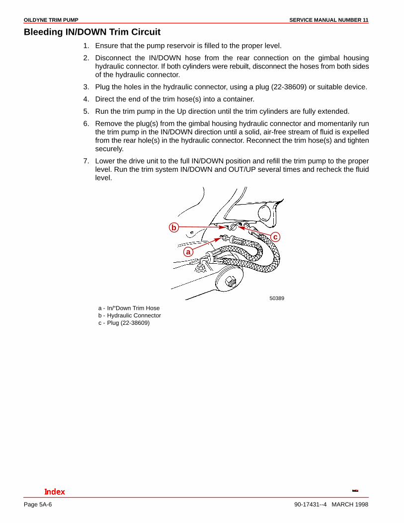
Bleeding IN/DOWN Trim Circuit1. Ensure that the pump reservoir is filled to the proper level.
2. Disconnect the IN/DOWN hose from the rear connection on the gimbal housinghydraulic connector. If both cylinders were rebuilt, disconnect the hoses from both sidesof the hydraulic connector.
3. Plug the holes in the hydraulic connector, using a plug (22-38609) or suitable device.
4. Direct the end of the trim hose(s) into a container.
5. Run the trim pump in the Up direction until the trim cylinders are fully extended.
6. Remove the plug(s) from the gimbal housing hydraulic connector and momentarily runthe trim pump in the IN/DOWN direction until a solid, air-free stream of fluid is expelledfrom the rear hole(s) in the hydraulic connector. Reconnect the trim hose(s) and tightensecurely.
7. Lower the drive unit to the full IN/DOWN position and refill the trim pump to the properlevel. Run the trim system IN/DOWN and OUT/UP several times and recheck the fluidlevel.
50389
a
bc
a - In/“Down Trim Hoseb - Hydraulic Connectorc - Plug (22-38609)
OILDYNE TRIM PUMPSERVICE MANUAL NUMBER 11
90-17431--4 MARCH 1998 Page 5A-7
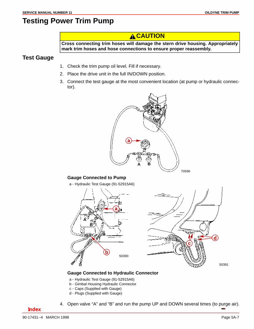
Testing Power Trim Pump
CAUTIONCross connecting trim hoses will damage the stern drive housing. Appropriatelymark trim hoses and hose connections to ensure proper reassembly.
Test Gauge1. Check the trim pump oil level. Fill if necessary.
2. Place the drive unit in the full IN/DOWN position.
3. Connect the test gauge at the most convenient location (at pump or hydraulic connec-tor).
70596
A B
a
Gauge Connected to Pumpa - Hydraulic Test Gauge (91-52915A6)
50390
AB
50391
a
b
cd
Gauge Connected to Hydraulic Connectora - Hydraulic Test Gauge (91-52915A6)b - Gimbal Housing Hydraulic Connectorc - Caps (Supplied with Gauge)d - Plugs (Supplied with Gauge)
4. Open valve “A” and “B” and run the pump UP and DOWN several times (to purge air).
OILDYNE TRIM PUMP SERVICE MANUAL NUMBER 11
90-17431--4 MARCH 1998Page 5A-8
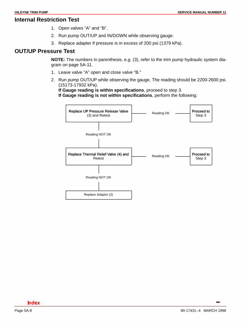
Internal Restriction Test1. Open valves “A” and “B”.
2. Run pump OUT/UP and IN/DOWN while observing gauge.
3. Replace adapter if pressure is in excess of 200 psi (1379 kPa).
OUT/UP Pressure TestNOTE: The numbers in parenthesis, e.g. (3), refer to the trim pump hydraulic system dia-gram on page 5A-11.
1. Leave valve “A” open and close valve “B.”
2. Run pump OUT/UP while observing the gauge. The reading should be 2200-2600 psi.(15173-17932 kPa).If Gauge reading is within specifications, proceed to step 3.If Gauge reading is not within specifications, perform the following:
Replace UP Pressure Release Valve Proceed toReplace UP Pressure Release Valve(3) and Retest
Reading OK Proceed toStep 3
Reading NOT OK
Replace Thermal Relief Valve (4) and Proceed toReplace Thermal Relief Valve (4) andRetest
Reading OK Proceed toStep 3
Reading NOT OK
Replace Adaptor (2)

OILDYNE TRIM PUMPSERVICE MANUAL NUMBER 11
90-17431--4 MARCH 1998 Page 5A-9
3. Run the pump OUT/UP until the gauge reading reaches 2200-2600 psi (15173-17932kPa). Stop pumping OUT/UP The pressure should not fall below 1900 psi (13104 kPa).If Gauge reading is 1900 psi (13104 kPa) or above, UP pressure test completed. IfGauge reading is below 1900 psi (13104 kPa) perform the following:
Check for External Oil Leaks, Up PressureCheck for External Oil Leaks,Correct and Retest
Reading OK Up PressureTest Completed
Reading NOT OK
Replace Thermal Relief Up PressureReplace Thermal Relief Valve (4) and Retest
Reading OK Up PressureTest Completed
Reading NOT OK
Install Trim Pump Rebuild Up PressureInstall Trim Pump Rebuild Kit and Retest
Reading OK Up PressureTest Completed
Reading NOT OK
Replace Adaptor (2)
OILDYNE TRIM PUMP SERVICE MANUAL NUMBER 11
90-17431--4 MARCH 1998Page 5A-10
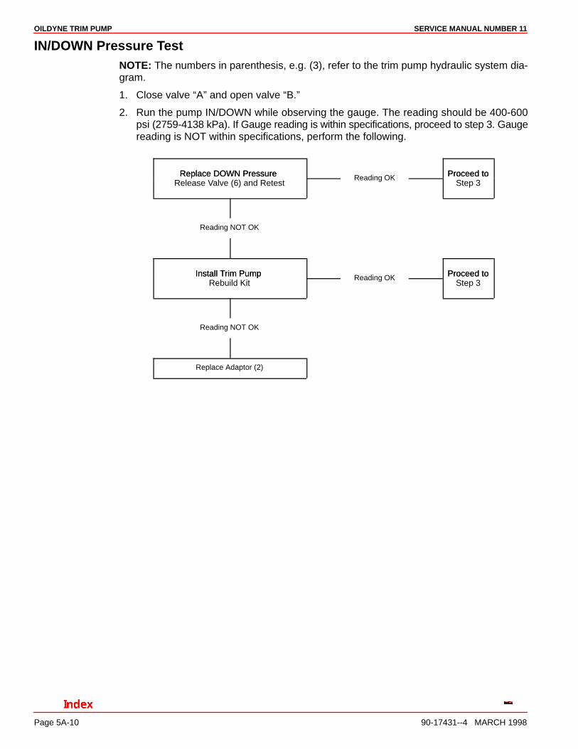
IN/DOWN Pressure TestNOTE: The numbers in parenthesis, e.g. (3), refer to the trim pump hydraulic system dia-gram.
1. Close valve “A” and open valve “B.”
2. Run the pump IN/DOWN while observing the gauge. The reading should be 400-600psi (2759-4138 kPa). If Gauge reading is within specifications, proceed to step 3. Gaugereading is NOT within specifications, perform the following.
Replace DOWN Pressure Proceed toReplace DOWN Pressure Release Valve (6) and Retest
Reading OK Proceed toStep 3
Reading NOT OK
Install Trim Pump Proceed toInstall Trim Pump Rebuild Kit
Reading OK Proceed toStep 3
Reading NOT OK
Replace Adaptor (2)
OILDYNE TRIM PUMPSERVICE MANUAL NUMBER 11
90-17431--4 MARCH 1998 Page 5A-11
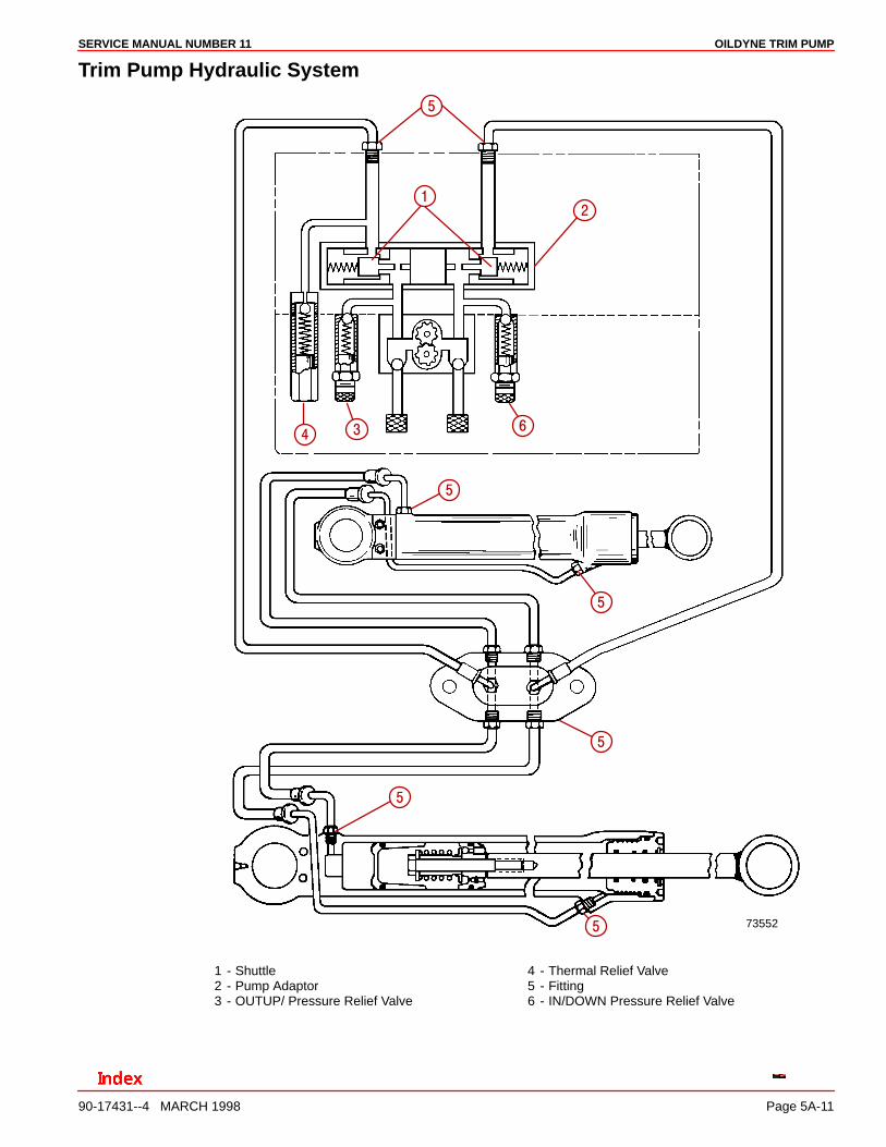
Trim Pump Hydraulic System
73552
��
�
���
�
�
�
�
�
1 - Shuttle2 - Pump Adaptor3 - OUTUP/ Pressure Relief Valve
4 - Thermal Relief Valve5 - Fitting6 - IN/DOWN Pressure Relief Valve
OILDYNE TRIM PUMP SERVICE MANUAL NUMBER 11
90-17431--4 MARCH 1998Page 5A-12
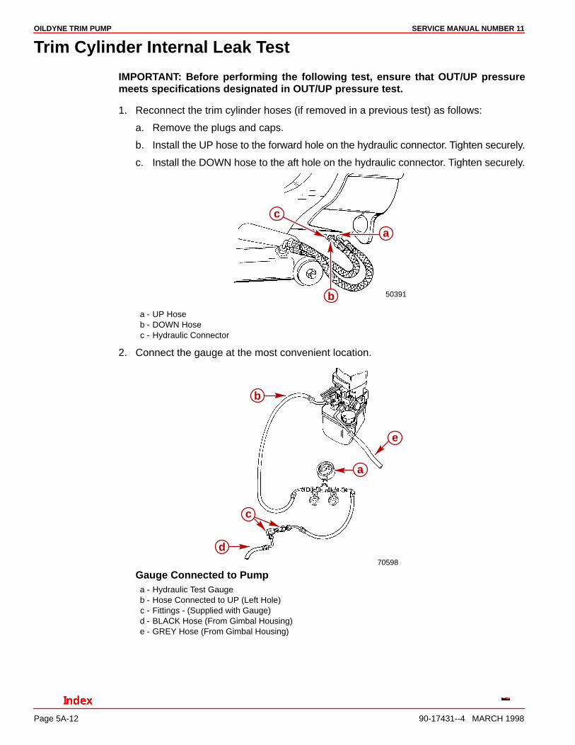
Trim Cylinder Internal Leak Test
IMPORTANT: Before performing the following test, ensure that OUT/UP pressuremeets specifications designated in OUT/UP pressure test.
1. Reconnect the trim cylinder hoses (if removed in a previous test) as follows:
a. Remove the plugs and caps.
b. Install the UP hose to the forward hole on the hydraulic connector. Tighten securely.
c. Install the DOWN hose to the aft hole on the hydraulic connector. Tighten securely.
50391
a
b
c
a - UP Hoseb - DOWN Hosec - Hydraulic Connector
2. Connect the gauge at the most convenient location.
70598
a
d
b
c
e
Gauge Connected to Pumpa - Hydraulic Test Gaugeb - Hose Connected to UP (Left Hole)c - Fittings - (Supplied with Gauge)d - BLACK Hose (From Gimbal Housing)e - GREY Hose (From Gimbal Housing)

OILDYNE TRIM PUMPSERVICE MANUAL NUMBER 11
90-17431--4 MARCH 1998 Page 5A-13
50390
A
B
b
c
a
Gauge Connected to Hydraulic Connectora - Test Gaugeb - Coupling (Supplied with Gauge)c - Front Hydraulic Connector Port
3. Open valves “A” and “B” and the run pump OUT/UP and IN/DOWN several times (topurge air).
4. Run the pump OUT/UP until the trim cylinders are fully extended; then, observe thegauge while pumping. The pressure should be 2200-2600 psi (15173-17932 kPa).
5. Stop pumping OUT/UP Pressure should not fall below 1900 psi (13104 kPa).
a. Reading below 1900 psi (13105 kPa) indicates a trim cylinder leak. Use the follow-ing steps to locate the faulty cylinder.
b. If the gauge is connected at the pump, reconnect the gauge at the gimbal housinghydraulic connector. Repeat step 2: then run the pump in the OUT/UP direction untilthe trim cylinder is fully extended.
c. Close the valve on the test gauge an repeat Steps 3 and 4.
• If Reading is now within specification: The trim cylinder on the same side that testgauge is connected to is faulty.
• If Reading is still not within specification: The trim cylinder on the opposite side fromwhere the test gauge is connected is faulty.
OILDYNE TRIM PUMP SERVICE MANUAL NUMBER 11
90-17431--4 MARCH 1998Page 5A-14
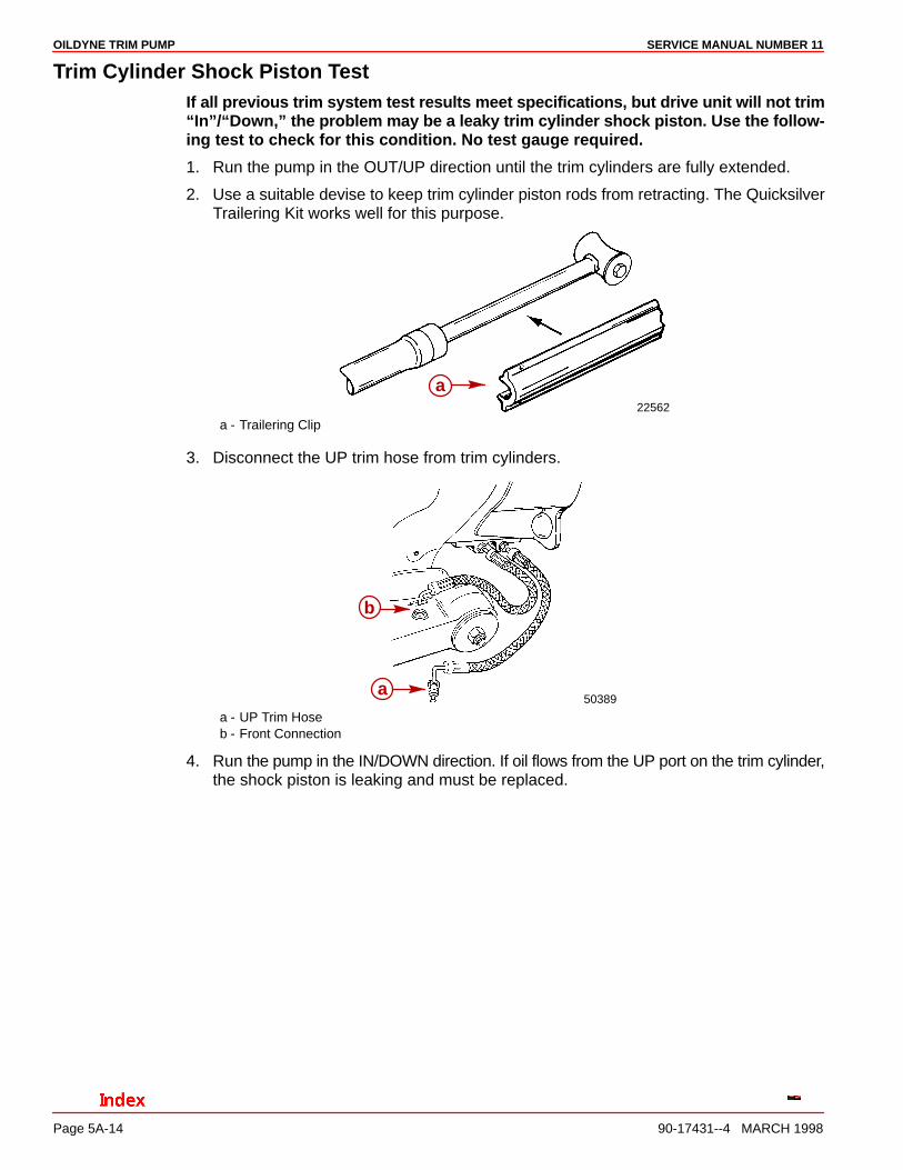
Trim Cylinder Shock Piston TestIf all previous trim system test results meet specifications, but drive unit will not trim“In”/“Down,” the problem may be a leaky trim cylinder shock piston. Use the follow-ing test to check for this condition. No test gauge required.
1. Run the pump in the OUT/UP direction until the trim cylinders are fully extended.
2. Use a suitable devise to keep trim cylinder piston rods from retracting. The QuicksilverTrailering Kit works well for this purpose.
22562
a
a - Trailering Clip
3. Disconnect the UP trim hose from trim cylinders.
50389
b
a
a - UP Trim Hoseb - Front Connection
4. Run the pump in the IN/DOWN direction. If oil flows from the UP port on the trim cylinder,the shock piston is leaking and must be replaced.
OILDYNE TRIM PUMPSERVICE MANUAL NUMBER 11
90-17431--4 MARCH 1998 Page 5A-15
Motor and Electrical Bench Tests
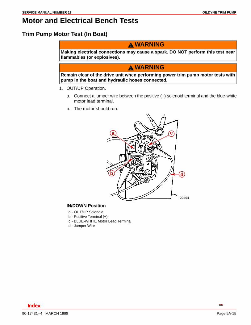
Trim Pump Motor Test (In Boat)
WARNINGMaking electrical connections may cause a spark. DO NOT perform this test nearflammables (or explosives).
WARNINGRemain clear of the drive unit when performing power trim pump motor tests withpump in the boat and hydraulic hoses connected.
1. OUT/UP Operation.
a. Connect a jumper wire between the positive (+) solenoid terminal and the blue-whitemotor lead terminal.
b. The motor should run.
22494
c
d
a
b
IN/DOWN Positiona - OUT/UP Solenoidb - Positive Terminal (+)c - BLUE-WHITE Motor Lead Terminald - Jumper Wire
OILDYNE TRIM PUMP SERVICE MANUAL NUMBER 11
90-17431--4 MARCH 1998Page 5A-16
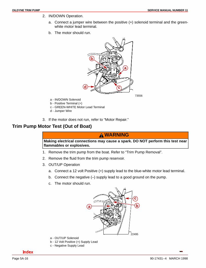
2. IN/DOWN Operation.
a. Connect a jumper wire between the positive (+) solenoid terminal and the green-white motor lead terminal.
b. The motor should run.
73556
a
cd
b
a - IN/DOWN Solenoidb - Positive Terminal (+)c - GREEN-WHITE Motor Lead Terminald - Jumper Wire
3. If the motor does not run, refer to “Motor Repair.”
Trim Pump Motor Test (Out of Boat)
WARNINGMaking electrical connections may cause a spark. DO NOT perform this test nearflammables or explosives.
1. Remove the trim pump from the boat. Refer to “Trim Pump Removal”.
2. Remove the fluid from the trim pump reservoir.
3. OUT/UP Operation
a. Connect a 12 volt Positive (+) supply lead to the blue-white motor lead terminal.
b. Connect the negative (–) supply lead to a good ground on the pump.
c. The motor should run.
22495
ba
c
a - OUT/UP Solenoidb - 12 Volt Positive (+) Supply Leadc - Negative Supply Lead

OILDYNE TRIM PUMPSERVICE MANUAL NUMBER 11
90-17431--4 MARCH 1998 Page 5A-17
4. IN/DOWN Position.
a. Connect a 12 volt Positive (+) supply lead to the green-white motor lead terminal.b. Connect the negative (–) supply lead to a good ground on the pump.c. The motor should run.
22494
a
b
c
a - IN/DOWN Solenoidb - 12 Volt Positive Supply (+) Leadc - GREEN-WHITE Motor Leadd - Jumper Wire
5. If the motor does not run, refer to “Motor Repair.”
Solenoid Test (Pump In Boat)
WARNINGDO NOT perform this test near flammables (or explosives) as a spark may occurwhen making connections.
CAUTIONRemain clear of the drive unit when performing power trim pump motor tests withpump in the boat and hydraulic hoses connected.
1. UP/OUT Solenoid.
a. Connect a jumper wire between the positive (+) solenoid terminal and the blue-whiteharness wire terminal.
b. The motor should run.
22495
d
a
b
c
a - OUT/UP Solenoidb - Positive (+) Solenoid Terminalc - BLUE-WHITE Harness Wire Terminald - Jumper Wire
OILDYNE TRIM PUMP SERVICE MANUAL NUMBER 11
90-17431--4 MARCH 1998Page 5A-18
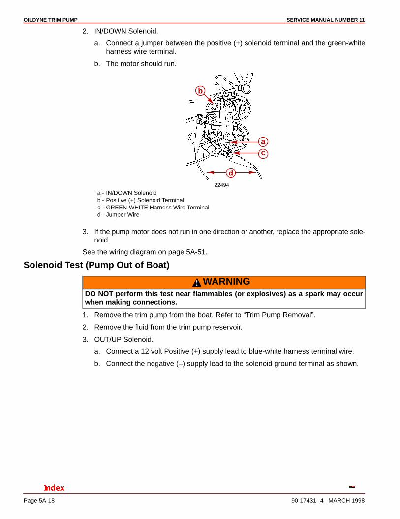
2. IN/DOWN Solenoid.
a. Connect a jumper between the positive (+) solenoid terminal and the green-whiteharness wire terminal.
b. The motor should run.
22494
b
ac
d
a - IN/DOWN Solenoidb - Positive (+) Solenoid Terminalc - GREEN-WHITE Harness Wire Terminald - Jumper Wire
3. If the pump motor does not run in one direction or another, replace the appropriate sole-noid.
See the wiring diagram on page 5A-51.
Solenoid Test (Pump Out of Boat)
WARNINGDO NOT perform this test near flammables (or explosives) as a spark may occurwhen making connections.
1. Remove the trim pump from the boat. Refer to “Trim Pump Removal”.
2. Remove the fluid from the trim pump reservoir.
3. OUT/UP Solenoid.
a. Connect a 12 volt Positive (+) supply lead to blue-white harness terminal wire.
b. Connect the negative (–) supply lead to the solenoid ground terminal as shown.

OILDYNE TRIM PUMPSERVICE MANUAL NUMBER 11
90-17431--4 MARCH 1998 Page 5A-19
c. Connect the ohmmeter leads to the large terminals on the solenoid.
22493
a
b
d
e
fc
a - OUT/UP Solenoidb - 12 volt Positive (+) Supply Leadc - Negative (–) Supply Leadd - Ohmmeter Leadse - BLUE-WHITE Harness Wire Terminalf - Solenoid Ground Terminal
4. Zero Ohms Reading (Full Continuity)-Solenoid is OK.High Ohms Reading (No Continuity)-Replace solenoid.
5. IN/DOWN Solenoid.
a. Connect a 12 volt positive (+) supply lead to the green-white harness wire terminal.
b. Connect the negative (–) supply lead to the solenoid ground terminal.
c. Connect the ohmmeter leads to the large terminals on the solenoid.
22494
c
d
b
a
ef
a - IN/DOWN Solenoidb - 12 Volt Positive (+) Supply Leadc - Negative (–) Supply Leadd - Ohmmeter Leadse - GREEN-WHITE Harness Wire Terminalf - Solenoid Ground Terminal
6. Zero Ohms Reading (Full Continuity)-Solenoid is OK.High Ohms Reading (No Continuity)-Replace solenoid.
See the wiring diagram on page 5A-51.
OILDYNE TRIM PUMP SERVICE MANUAL NUMBER 11
90-17431--4 MARCH 1998Page 5A-20
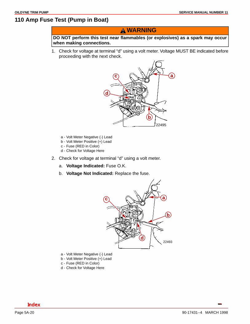
110 Amp Fuse Test (Pump in Boat)
WARNINGDO NOT perform this test near flammables (or explosives) as a spark may occurwhen making connections.
1. Check for voltage at terminal “d” using a volt meter. Voltage MUST BE indicated beforeproceeding with the next check.
22495
a
b
c
d
a - Volt Meter Negative (-) Leadb - Volt Meter Positive (+) Leadc - Fuse (RED in Color)d - Check for Voltage Here
2. Check for voltage at terminal “d” using a volt meter.
a. Voltage Indicated: Fuse O.K.
b. Voltage Not Indicated: Replace the fuse.
22493
a
b
c
d
a - Volt Meter Negative (-) Leadb - Volt Meter Positive (+) Leadc - Fuse (RED in Color)d - Check for Voltage Here

OILDYNE TRIM PUMPSERVICE MANUAL NUMBER 11
90-17431--4 MARCH 1998 Page 5A-21
110 Amp Fuse Test (Pump Out of Boat)1. Connect the ohmmeter leads between the terminals on the fuse.
22493
b
a
a - 110 Amp Fuse (Red)b - Ohmmeter Leads
Zero Ohms Reading (Full Continuity)-Fuse OK.High Ohms Reading (No Continuity)-Replace fuse.
20 Amp Fuse Test1. Remove the fuse from the fuse holder.
22496
a
a - Fuse Holder
OILDYNE TRIM PUMP SERVICE MANUAL NUMBER 11
90-17431--4 MARCH 1998Page 5A-22
2. Connect one ohmmeter lead to each end of the fuse.
22497
a
b
a - 20 Amp Fuseb - Ohmmeter Leads
Zero Ohms Reading (Full Continuity)-Fuse OK.High Ohms Reading (No Continuity)-Replace fuse.
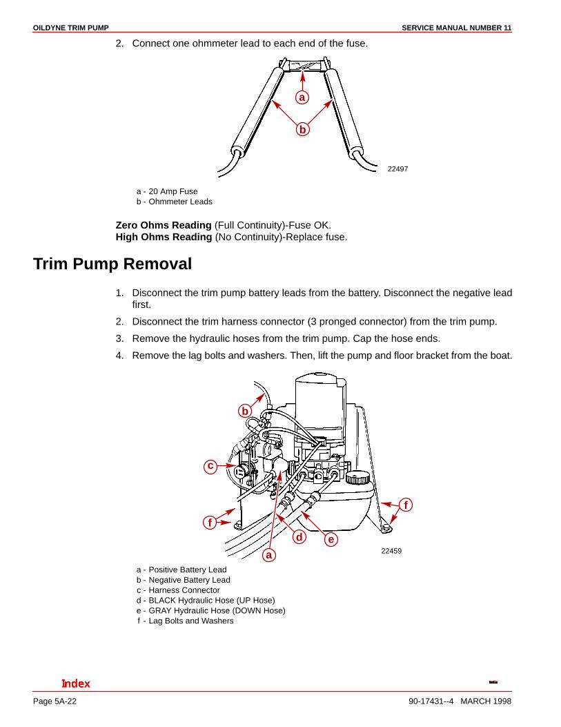
Trim Pump Removal
1. Disconnect the trim pump battery leads from the battery. Disconnect the negative leadfirst.
2. Disconnect the trim harness connector (3 pronged connector) from the trim pump.
3. Remove the hydraulic hoses from the trim pump. Cap the hose ends.
4. Remove the lag bolts and washers. Then, lift the pump and floor bracket from the boat.
22459
f
ed
a
f
c
b
a - Positive Battery Leadb - Negative Battery Leadc - Harness Connectord - BLACK Hydraulic Hose (UP Hose)e - GRAY Hydraulic Hose (DOWN Hose)f - Lag Bolts and Washers

OILDYNE TRIM PUMPSERVICE MANUAL NUMBER 11
90-17431--4 MARCH 1998 Page 5A-23
Hydraulic Repair
Disassembly1. Disconnect the trim motor wires.
70359
c
a
ba - BLUE/WHITE Motor Wireb - GREEN/WHITE Motor Wirec - BLACK Ground Wire
2. Remove the mounting bolts and trim pump from the floor bracket.
22548
b
ca
a - Trim Pumpb - Floor Bracketc - Mounting Bolts
3. Remove the solenoids if replacement is necessary.
70232
c
c
b
a
c
c
a - UP Solenoidb - DOWN Solenoidc - Mounting Bolts (2 on Each Solenoid)

OILDYNE TRIM PUMP SERVICE MANUAL NUMBER 11
90-17431--4 MARCH 1998Page 5A-24
4. Remove the pump reservoir.
2254723860
Earlierstyle
reservoir
Laterstyle
reservoirba
a - Pump Reservoirb - Bolt and O-ring - Spacer
Filter Replacement1. Remove the filter by twisting while pulling upward.
70932
a
a - Filter
2. Install a new filter.
22547
b
a
a - Filterb - 5/8 in. Socket
OILDYNE TRIM PUMPSERVICE MANUAL NUMBER 11
90-17431--4 MARCH 1998 Page 5A-25
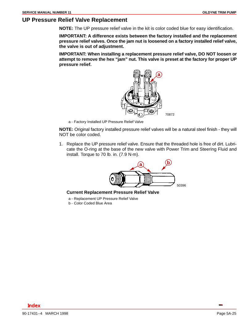
UP Pressure Relief Valve ReplacementNOTE: The UP pressure relief valve in the kit is color coded blue for easy identification.
IMPORTANT: A difference exists between the factory installed and the replacementpressure relief valves. Once the jam nut is loosened on a factory installed relief valve,the valve is out of adjustment.
IMPORTANT: When installing a replacement pressure relief valve, DO NOT loosen orattempt to remove the hex “jam” nut. This valve is preset at the factory for proper UPpressure relief.
70872
a
a - Factory Installed UP Pressure Relief Valve
NOTE: Original factory installed pressure relief valves will be a natural steel finish - they willNOT be color coded.
1. Replace the UP pressure relief valve. Ensure that the threaded hole is free of dirt. Lubri-cate the O-ring at the base of the new valve with Power Trim and Steering Fluid andinstall. Torque to 70 lb. in. (7.9 N·m).
50396
ba
Current Replacement Pressure Relief Valvea - Replacement UP Pressure Relief Valveb - Color Coded Blue Area
OILDYNE TRIM PUMP SERVICE MANUAL NUMBER 11
90-17431--4 MARCH 1998Page 5A-26
50396 70872 50396
c d
e
fb
a
Original Factory Installed Pressure Relief Valvea - Original Factory Installed UP Pressure Relief Valveb - Jam Nut - Loosen Before Removing the Valvec - Be Sure to Remove the Pump Body Components (Spring, eyelet, Check Ball) - Discardd - Replacement UP Pressure Relief Valve (Blue) - Use the Base of the valve for tighteninge - Jam Nut - DO NOT TURN or Attempt to Loosenf - O-ring
DOWN Pressure Relief Valve ReplacementNOTE: The DOWN pressure relief valve in the kit is color coded green for easy identification.
IMPORTANT: A difference exists between the factory installed and the replacementpressure relief valves. Once the jam nut is loosened on a factory installed relief valve,the valve is out of adjustment.
IMPORTANT: When installing a replacement pressure relief valve, DO NOT loosen orattempt to remove the hex “jam” nut. This valve is preset at the factory for properDOWN pressure relief.
70872
a
a - Factory Installed DOWN Pressure Relief Valve
50396
ba
a - Replacement DOWN Pressure Relief Valveb - Color Coded Green Area
OILDYNE TRIM PUMPSERVICE MANUAL NUMBER 11
90-17431--4 MARCH 1998 Page 5A-27
1. Replace the DOWN pressure relief valve. Remove the pump body components and dis-card. Ensure that the threaded hole is free of dirt. Lubricate the O-ring at the base of thenew valve with Power Trim and Steering Fluid and install. Torque to 70 lb. in. (7.9 N·m).Use the base of the valve for tightening; DO NOT TURN or attempt to loosen the jamnut.
50396 70872 50396
a
b
c d
e
f
Original Factory Installed Pressure Relief Valvea - Original Factory Installed DOWN Pressure Relief Valveb - Jam Nut - Loosen Before Removing the Valvec - Pump Body Components (Spring, Eyelet, Check Ball)d - Replacement DOWN Pressure Relief Valve (GREEN)e - Jam Nutf - O-ring
Thermal Relief Valve ReplacementNOTE: The Thermal Relief Valve in the kit is color coded gold for easy identification.
IMPORTANT: The thermal relief valve is factory preset. DO NOT loosen or attempt toseparate the component parts. Do not use a wrench on the upper gold colored fitting.Use a wrench on the lower hex-fitting to tighten the relief valve.
1. Replace the thermal relief valve. Remove the pump body components and discard.Ensure that the threaded hole is free of dirt. Lubricate the O-ring at the base of the newvalve with Power Trim and Steering Fluid and install. Torque to 70 lb. in. (7.9 N·m). Usethe base of the valve for tightening; DO NOT TURN or attempt to loosen the jam nut.
70836
d
b
c
a
a - Thermal Relief Valveb - Replacement Thermal Relief Valve (Gold)c - O-ringd - Pump Body Components (Spring, Eyelet, Check Ball)
OILDYNE TRIM PUMP SERVICE MANUAL NUMBER 11
90-17431--4 MARCH 1998Page 5A-28
Pump ReplacementNOTE: The pump is cannot be re-built. If the pump is defective, replace it as an assembly.
1. Remove the pump attaching screws with a hex lobular socket or standard 3/16 in.(188mm) socket and the pump. Do NOT loosen the pump assembly screws.
70870
a
b
a - Screwb - Pump Assembly Screws
2. Remove the O-rings from the old pump and install them on the new pump.
3. Lubricate the lip of the adapter seal with light weight oil.
22545
a
b
a - O-ringsb - Adapter Seal
4. Install the pump and torque the pump screws to 70 lb. in. (7.9 N·m) using a hex lobularsocket or standard 3/16 in. (188mm) socket.
70870
a
a - Screws

OILDYNE TRIM PUMPSERVICE MANUAL NUMBER 11
90-17431--4 MARCH 1998 Page 5A-29
Adapter Replacement1. Remove the pump motor attaching screws and remove the pump motor.
70599
a
b
a - Pump Motorb - Screws (2)
2. Remove and discard the adapter to reservoir O-ring.
70869
b
a
a - Adapterb - O-ring
3. Remove and discard the motor to adapter O-ring.
4. If present, remove the vent screw (dipstick) from the old adapter.
5. If present, install the vent screw (dipstick) and new O-ring into the new adaptor.
6. Ensure that the coupling is installed so that the shallow slot is toward the reservoir. Lubri-cate the coupling with 2-4-C Marine Lubricant with Teflon.
70600
ca
b
a - Adapterb - O-ringc - Coupling - (Shallow Slot Toward Reservoir)
OILDYNE TRIM PUMP SERVICE MANUAL NUMBER 11
90-17431--4 MARCH 1998Page 5A-30
7. Align the motor shaft with the coupling and install the motor onto the adapter. Positionthe motor as shown and secure with screws. Tighten securely.
22548
22496
c
b
c
a
a - Motor Shaftb - Couplingc - Screws (Opposite Corners)
Adapter Repair
INTERNAL O-RING and POPPET VALVE REPLACEMENT
1. Remove the hex plug retainers and springs (one on each side).
70871
a b
a - Hex Plug Retainers (2)b - Springs (2)
OILDYNE TRIM PUMPSERVICE MANUAL NUMBER 11
90-17431--4 MARCH 1998 Page 5A-31
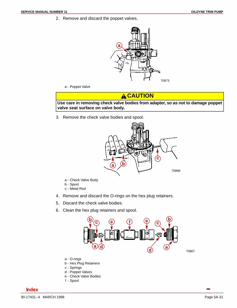
2. Remove and discard the poppet valves.
70873
a
a - Poppet Valve
CAUTIONUse care in removing check valve bodies from adapter, so as not to damage poppetvalve seat surface on valve body.
3. Remove the check valve bodies and spool.
70868
a bc
a - Check Valve Bodyb - Spoolc - Metal Rod
4. Remove and discard the O-rings on the hex plug retainers.
5. Discard the check valve bodies.
6. Clean the hex plug retainers and spool.
70867d
b e f e bc
ada
c
a - O-ringsb - Hex Plug Retainersc - Springsd - Poppet Valvese - Check Valve Bodiesf - Spool
OILDYNE TRIM PUMP SERVICE MANUAL NUMBER 11
90-17431--4 MARCH 1998Page 5A-32
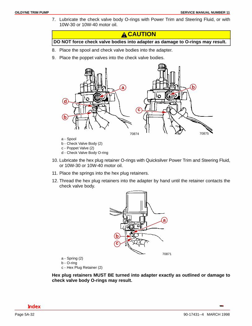
7. Lubricate the check valve body O-rings with Power Trim and Steering Fluid, or with10W-30 or 10W-40 motor oil.
CAUTIONDO NOT force check valve bodies into adapter as damage to O-rings may result.
8. Place the spool and check valve bodies into the adapter.
9. Place the poppet valves into the check valve bodies.
70874 70875
a
d
b
b
c
a - Spoolb - Check Valve Body (2)c - Poppet Valve (2)d - Check Valve Body O-ring
10. Lubricate the hex plug retainer O-rings with Quicksilver Power Trim and Steering Fluid,or 10W-30 or 10W-40 motor oil.
11. Place the springs into the hex plug retainers.
12. Thread the hex plug retainers into the adapter by hand until the retainer contacts thecheck valve body.
70871
a
bc
a - Spring (2)b - O-ringc - Hex Plug Retainer (2)
Hex plug retainers MUST BE turned into adapter exactly as outlined or damage tocheck valve body O-rings may result.
OILDYNE TRIM PUMPSERVICE MANUAL NUMBER 11
90-17431--4 MARCH 1998 Page 5A-33
13. Tighten the hex plug retainer securely on each side.
70866
a
a
a - Hex Plug Retainer
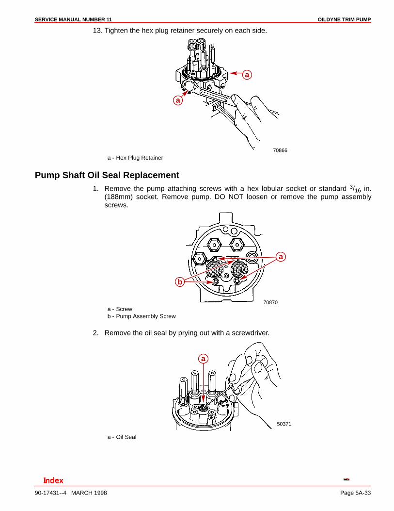
Pump Shaft Oil Seal Replacement1. Remove the pump attaching screws with a hex lobular socket or standard 3/16 in.
(188mm) socket. Remove pump. DO NOT loosen or remove the pump assemblyscrews.
70870
a
b
a - Screwb - Pump Assembly Screw
2. Remove the oil seal by prying out with a screwdriver.
50371
a
a - Oil Seal
OILDYNE TRIM PUMP SERVICE MANUAL NUMBER 11
90-17431--4 MARCH 1998Page 5A-34
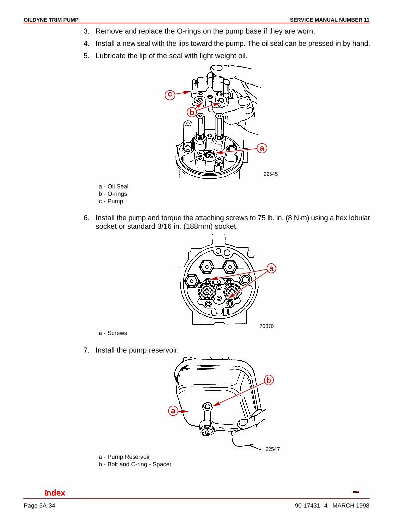
3. Remove and replace the O-rings on the pump base if they are worn.
4. Install a new seal with the lips toward the pump. The oil seal can be pressed in by hand.
5. Lubricate the lip of the seal with light weight oil.
22545
c
b
a
a - Oil Sealb - O-ringsc - Pump
6. Install the pump and torque the attaching screws to 75 lb. in. (8 N·m) using a hex lobularsocket or standard 3/16 in. (188mm) socket.
70870
a
a - Screws
7. Install the pump reservoir.
22547
b
a
a - Pump Reservoirb - Bolt and O-ring - Spacer
OILDYNE TRIM PUMPSERVICE MANUAL NUMBER 11
90-17431--4 MARCH 1998 Page 5A-35
Motor Repair
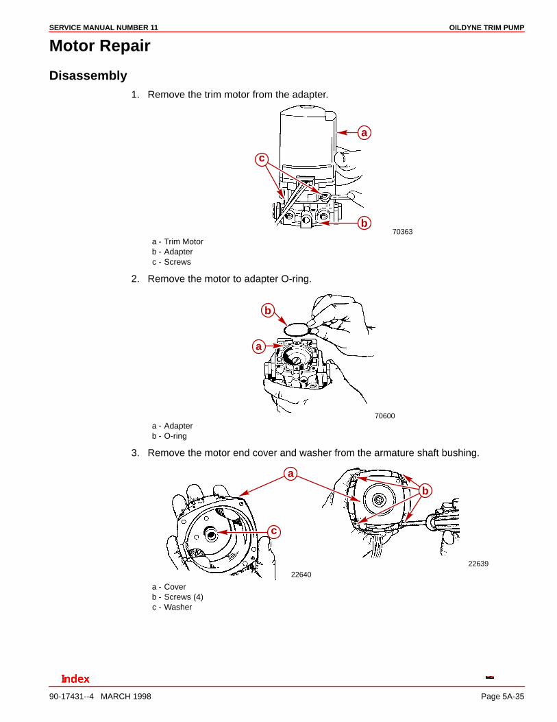
Disassembly1. Remove the trim motor from the adapter.
70363
a
b
c
a - Trim Motorb - Adapterc - Screws
2. Remove the motor to adapter O-ring.
70600
b
a
a - Adapterb - O-ring
3. Remove the motor end cover and washer from the armature shaft bushing.
22639
22640
c
a
b
a - Coverb - Screws (4)c - Washer
OILDYNE TRIM PUMP SERVICE MANUAL NUMBER 11
90-17431--4 MARCH 1998Page 5A-36
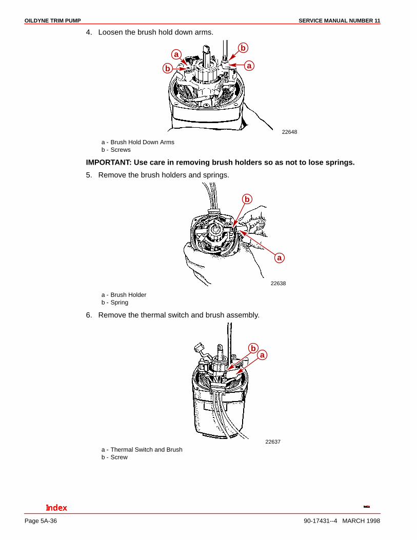
4. Loosen the brush hold down arms.
22648
a
b
b
a
a - Brush Hold Down Armsb - Screws
IMPORTANT: Use care in removing brush holders so as not to lose springs.
5. Remove the brush holders and springs.
22638
b
a
a - Brush Holderb - Spring
6. Remove the thermal switch and brush assembly.
22637
ab
a - Thermal Switch and Brushb - Screw

OILDYNE TRIM PUMPSERVICE MANUAL NUMBER 11
90-17431--4 MARCH 1998 Page 5A-37
7. Remove the brush assembly mounting bracket.
22636
a
a
b
a - Brush Assembly Bracketb - Screws
8. Remove the armature and thrust washer from the motor housing.
22499
a
b
c
a - Armatureb - Thrust Washerc - Motor Housing
9. Remove the field assembly from the motor housing.
22501
a
b
a - Field Assemblyb - Motor Housing
OILDYNE TRIM PUMP SERVICE MANUAL NUMBER 11
90-17431--4 MARCH 1998Page 5A-38
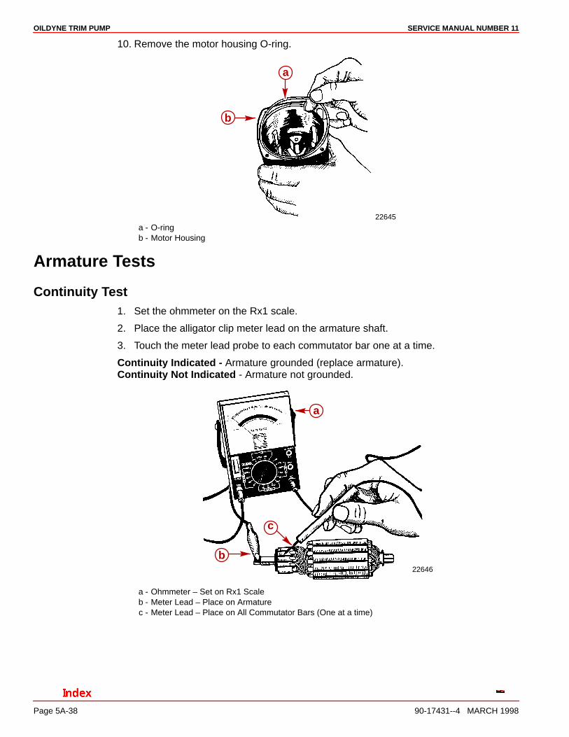
10. Remove the motor housing O-ring.
22645
a
b
a - O-ringb - Motor Housing
Armature Tests
Continuity Test1. Set the ohmmeter on the Rx1 scale.
2. Place the alligator clip meter lead on the armature shaft.
3. Touch the meter lead probe to each commutator bar one at a time.
Continuity Indicated - Armature grounded (replace armature).Continuity Not Indicated - Armature not grounded.
22646
a
c
b
a - Ohmmeter – Set on Rx1 Scaleb - Meter Lead – Place on Armaturec - Meter Lead – Place on All Commutator Bars (One at a time)
OILDYNE TRIM PUMPSERVICE MANUAL NUMBER 11
90-17431--4 MARCH 1998 Page 5A-39
Test for Shorts1. Check the armature on a growler (follow the growler manufacturers instructions). Re-
place the armature if it has a short.
Cleaning Commutator1. Clean the commutator with “00” garnet grit sandpaper. DO NOT use emery paper.
2. Check the gaps between the commutator bars for material. Remove material if present.
22647b
a
a - Commutatorb - Gap
Field Tests
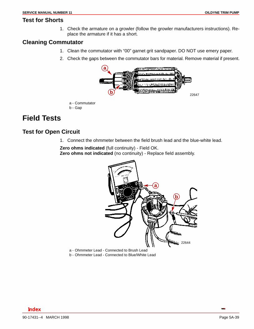
Test for Open Circuit1. Connect the ohmmeter between the field brush lead and the blue-white lead.
Zero ohms indicated (full continuity) - Field OK.Zero ohms not indicated (no continuity) - Replace field assembly.
22644
a
b
a - Ohmmeter Lead - Connected to Brush Leadb - Ohmmeter Lead - Connected to Blue/White Lead
OILDYNE TRIM PUMP SERVICE MANUAL NUMBER 11
90-17431--4 MARCH 1998Page 5A-40
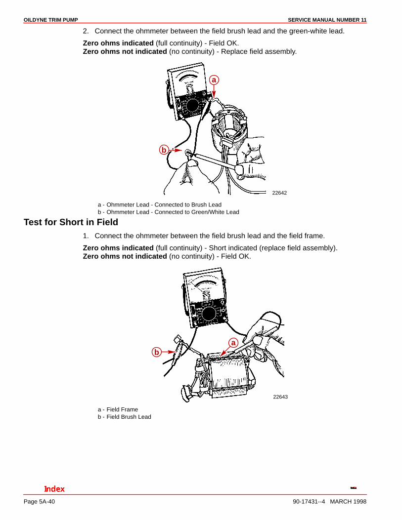
2. Connect the ohmmeter between the field brush lead and the green-white lead.
Zero ohms indicated (full continuity) - Field OK.Zero ohms not indicated (no continuity) - Replace field assembly.
22642
a
b
a - Ohmmeter Lead - Connected to Brush Leadb - Ohmmeter Lead - Connected to Green/White Lead
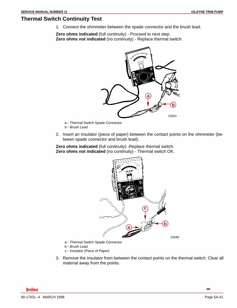
Test for Short in Field1. Connect the ohmmeter between the field brush lead and the field frame.
Zero ohms indicated (full continuity) - Short indicated (replace field assembly).Zero ohms not indicated (no continuity) - Field OK.
22643
ab
a - Field Frameb - Field Brush Lead
OILDYNE TRIM PUMPSERVICE MANUAL NUMBER 11
90-17431--4 MARCH 1998 Page 5A-41
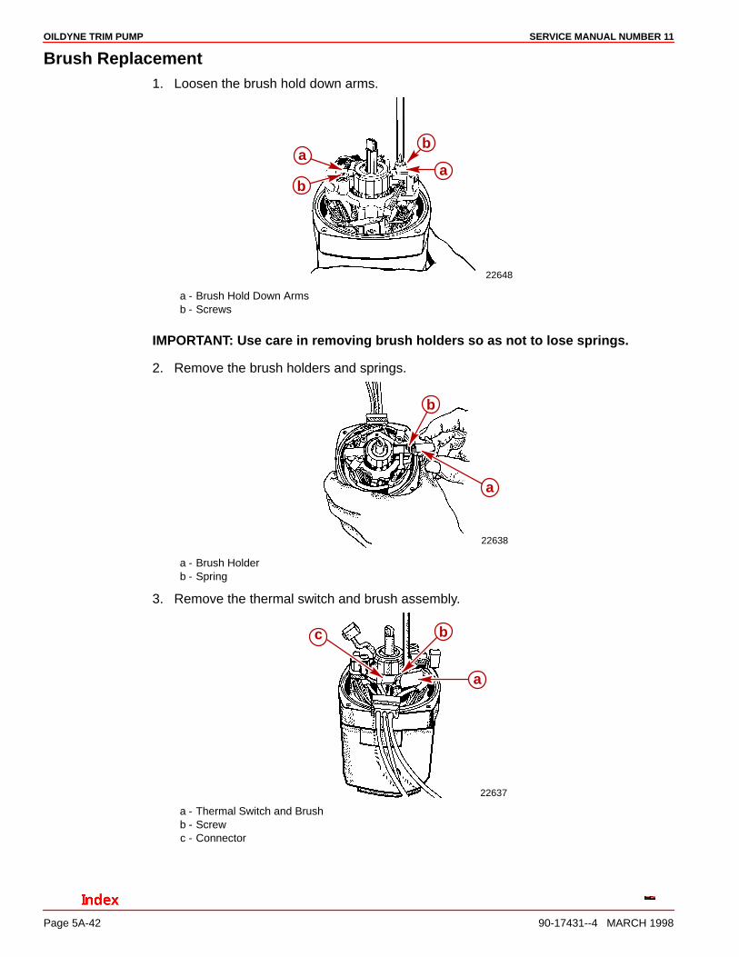
Thermal Switch Continuity Test1. Connect the ohmmeter between the spade connector and the brush lead.
Zero ohms indicated (full continuity) - Proceed to next step.Zero ohms not indicated (no continuity) - Replace thermal switch.
22631
b
a
a - Thermal Switch Spade Connectorb - Brush Lead
2. Insert an insulator (piece of paper) between the contact points on the ohmmeter (be-tween spade connector and brush lead).
Zero ohms indicated (full continuity) -Replace thermal switch.Zero ohms not indicated (no continuity) - Thermal switch OK.
22649
b
c
a
a - Thermal Switch Spade Connectorb - Brush Leadc - Insulator (Piece of Paper)
3. Remove the insulator from between the contact points on the thermal switch. Clear allmaterial away from the points.
OILDYNE TRIM PUMP SERVICE MANUAL NUMBER 11
90-17431--4 MARCH 1998Page 5A-42
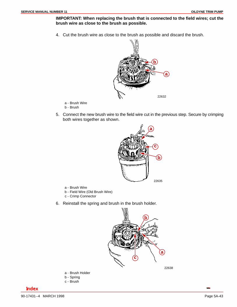
Brush Replacement1. Loosen the brush hold down arms.
22648
a
ba
b
a - Brush Hold Down Armsb - Screws
IMPORTANT: Use care in removing brush holders so as not to lose springs.
2. Remove the brush holders and springs.
22638
b
a
a - Brush Holderb - Spring
3. Remove the thermal switch and brush assembly.
22637
a
bc
a - Thermal Switch and Brushb - Screwc - Connector
OILDYNE TRIM PUMPSERVICE MANUAL NUMBER 11
90-17431--4 MARCH 1998 Page 5A-43
IMPORTANT: When replacing the brush that is connected to the field wires; cut thebrush wire as close to the brush as possible.
4. Cut the brush wire as close to the brush as possible and discard the brush.
22632
b
a
a - Brush Wireb - Brush
5. Connect the new brush wire to the field wire cut in the previous step. Secure by crimpingboth wires together as shown.
22635
a
c
b
a - Brush Wireb - Field Wire (Old Brush Wire)c - Crimp Connector
6. Reinstall the spring and brush in the brush holder.
22638
b
ac
a - Brush Holderb - Springc - Brush
OILDYNE TRIM PUMP SERVICE MANUAL NUMBER 11
90-17431--4 MARCH 1998Page 5A-44
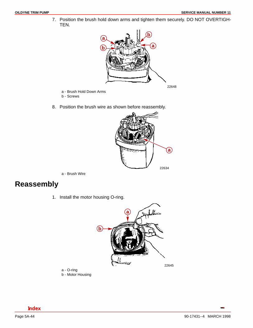
7. Position the brush hold down arms and tighten them securely. DO NOT OVERTIGH-TEN.
22648
a
ba
b
a - Brush Hold Down Armsb - Screws
8. Position the brush wire as shown before reassembly.
22634
a
a - Brush Wire
Reassembly
1. Install the motor housing O-ring.
22645
a
b
a - O-ringb - Motor Housing
OILDYNE TRIM PUMPSERVICE MANUAL NUMBER 11
90-17431--4 MARCH 1998 Page 5A-45
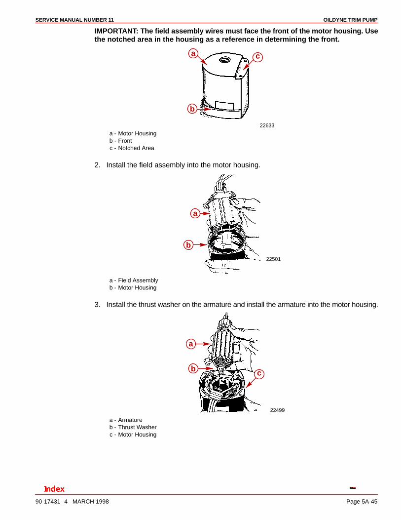
IMPORTANT: The field assembly wires must face the front of the motor housing. Usethe notched area in the housing as a reference in determining the front.
22633
c
b
a
a - Motor Housingb - Frontc - Notched Area
2. Install the field assembly into the motor housing.
22501
a
b
a - Field Assemblyb - Motor Housing
3. Install the thrust washer on the armature and install the armature into the motor housing.
22499
c
a
b
a - Armatureb - Thrust Washerc - Motor Housing

OILDYNE TRIM PUMP SERVICE MANUAL NUMBER 11
90-17431--4 MARCH 1998Page 5A-46
4. Install the brush assembly mounting. Tighten the screws securely.
22636
a
a
b
a - Brush Assembly Mounting Bracketb - Screws
5. Install the thermal switch and connect the black wire. DO NOT overtighten the screw.
22637
ab
c
a - Thermal Switchb - Screwc - Black Wire Connector
6. Install the springs and brushes in the brush holders.
22638
b
a
c
a - Brush Holdersb - Springsc - Brushes
OILDYNE TRIM PUMPSERVICE MANUAL NUMBER 11
90-17431--4 MARCH 1998 Page 5A-47
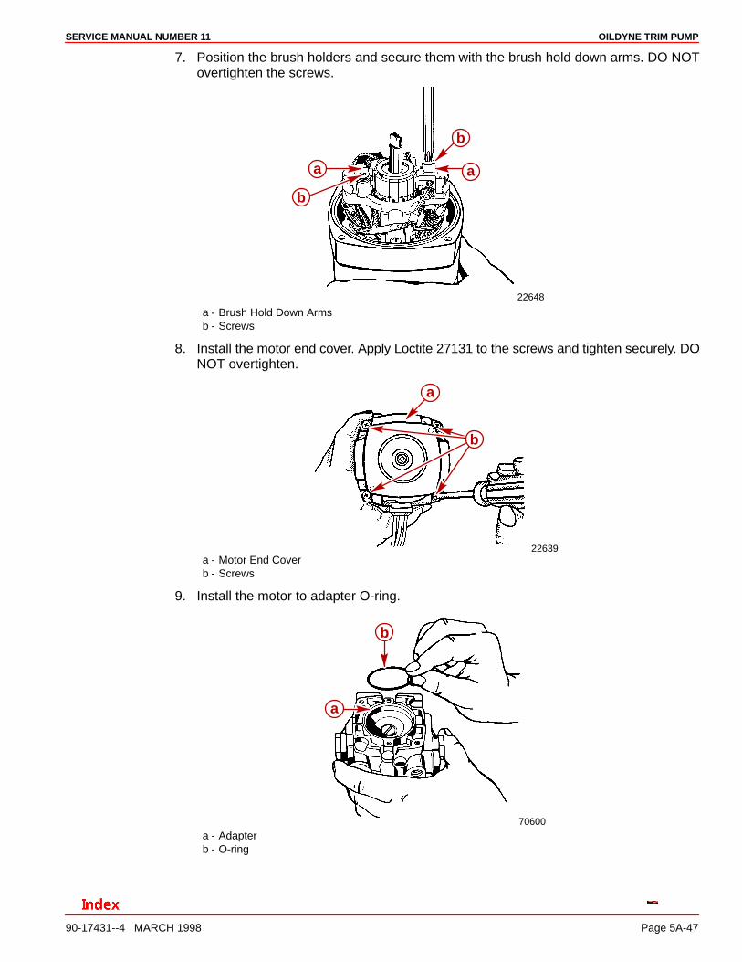
7. Position the brush holders and secure them with the brush hold down arms. DO NOTovertighten the screws.
22648
a
b
a
b
a - Brush Hold Down Armsb - Screws
8. Install the motor end cover. Apply Loctite 27131 to the screws and tighten securely. DONOT overtighten.
22639
a
b
a - Motor End Coverb - Screws
9. Install the motor to adapter O-ring.
70600
b
a
a - Adapterb - O-ring
OILDYNE TRIM PUMP SERVICE MANUAL NUMBER 11
90-17431--4 MARCH 1998Page 5A-48
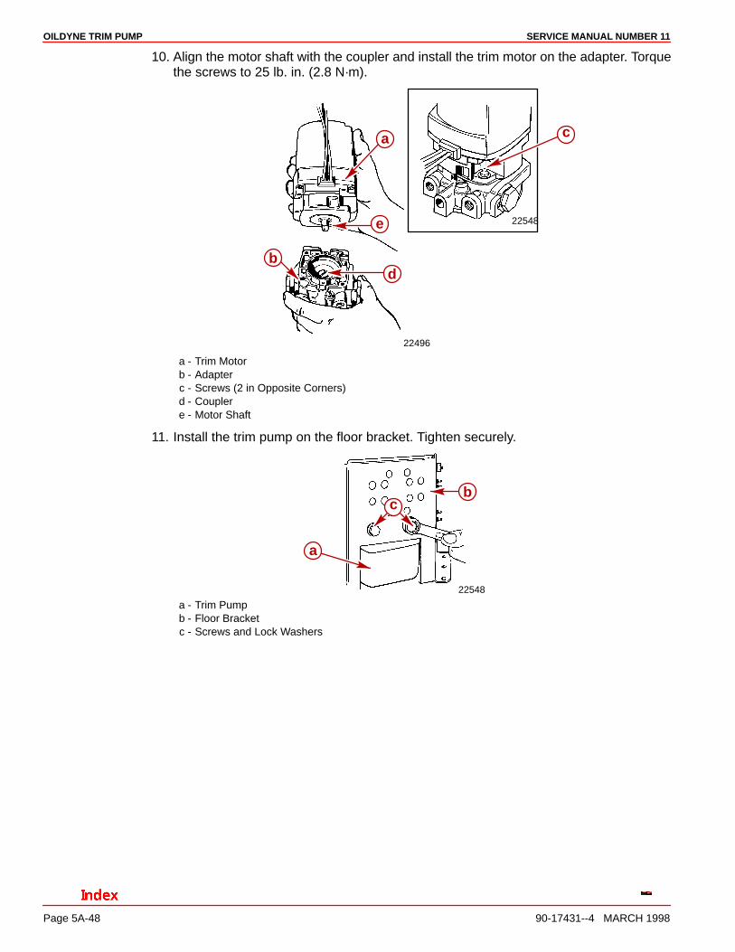
10. Align the motor shaft with the coupler and install the trim motor on the adapter. Torquethe screws to 25 lb. in. (2.8 N·m).
22548
22496
ca
e
db
a - Trim Motorb - Adapterc - Screws (2 in Opposite Corners)d - Couplere - Motor Shaft
11. Install the trim pump on the floor bracket. Tighten securely.
22548
bc
a
a - Trim Pumpb - Floor Bracketc - Screws and Lock Washers
OILDYNE TRIM PUMPSERVICE MANUAL NUMBER 11
90-17431--4 MARCH 1998 Page 5A-49
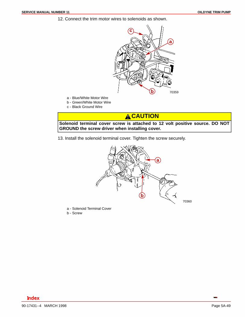
12. Connect the trim motor wires to solenoids as shown.
70359
a
b
c
a - Blue/White Motor Wireb - Green/White Motor Wirec - Black Ground Wire
CAUTIONSolenoid terminal cover screw is attached to 12 volt positive source. DO NOTGROUND the screw driver when installing cover.
13. Install the solenoid terminal cover. Tighten the screw securely.
70360
a
b
a - Solenoid Terminal Coverb - Screw
OILDYNE TRIM PUMP SERVICE MANUAL NUMBER 11
90-17431--4 MARCH 1998Page 5A-50
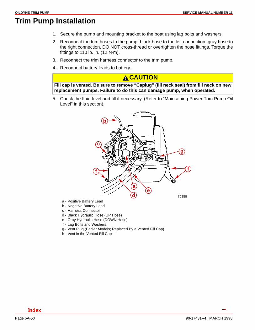
Trim Pump Installation
1. Secure the pump and mounting bracket to the boat using lag bolts and washers.
2. Reconnect the trim hoses to the pump; black hose to the left connection, gray hose tothe right connection. DO NOT cross-thread or overtighten the hose fittings. Torque thefittings to 110 lb. in. (12 N·m).
3. Reconnect the trim harness connector to the trim pump.
4. Reconnect battery leads to battery.
CAUTIONFill cap is vented. Be sure to remove “Caplug” (fill neck seal) from fill neck on newreplacement pumps. Failure to do this can damage pump, when operated.
5. Check the fluid level and fill if necessary. (Refer to “Maintaining Power Trim Pump OilLevel” in this section).
70358
g
f
ed
b
a
c
f
a - Positive Battery Leadb - Negative Battery Leadc - Harness Connectord - Black Hydraulic Hose (UP Hose)e - Gray Hydraulic Hose (DOWN Hose)f - Lag Bolts and Washersg - Vent Plug (Earlier Models; Replaced By a Vented Fill Cap)h - Vent in the Vented Fill Cap
OILDYNE TRIM PUMPSERVICE MANUAL NUMBER 11
90-17431--4 MARCH 1998 Page 5A-51
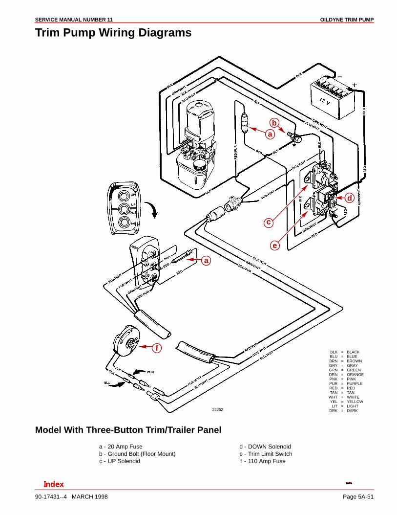
Trim Pump Wiring Diagrams
22252
BLK = BLACKBLU = BLUEBRN = BROWNGRY = GRAYGRN = GREENORN = ORANGEPNK = PINKPUR = PURPLERED = REDTAN = TAN
WHT = WHITEYEL = YELLOWLIT = LIGHT
DRK = DARK
d
e
c
ba
a
f
Model With Three-Button Trim/Trailer Panel
a - 20 Amp Fuseb - Ground Bolt (Floor Mount)c - UP Solenoid
d - DOWN Solenoide - Trim Limit Switchf - 110 Amp Fuse
OILDYNE TRIM PUMP SERVICE MANUAL NUMBER 11
90-17431--4 MARCH 1998Page 5A-52
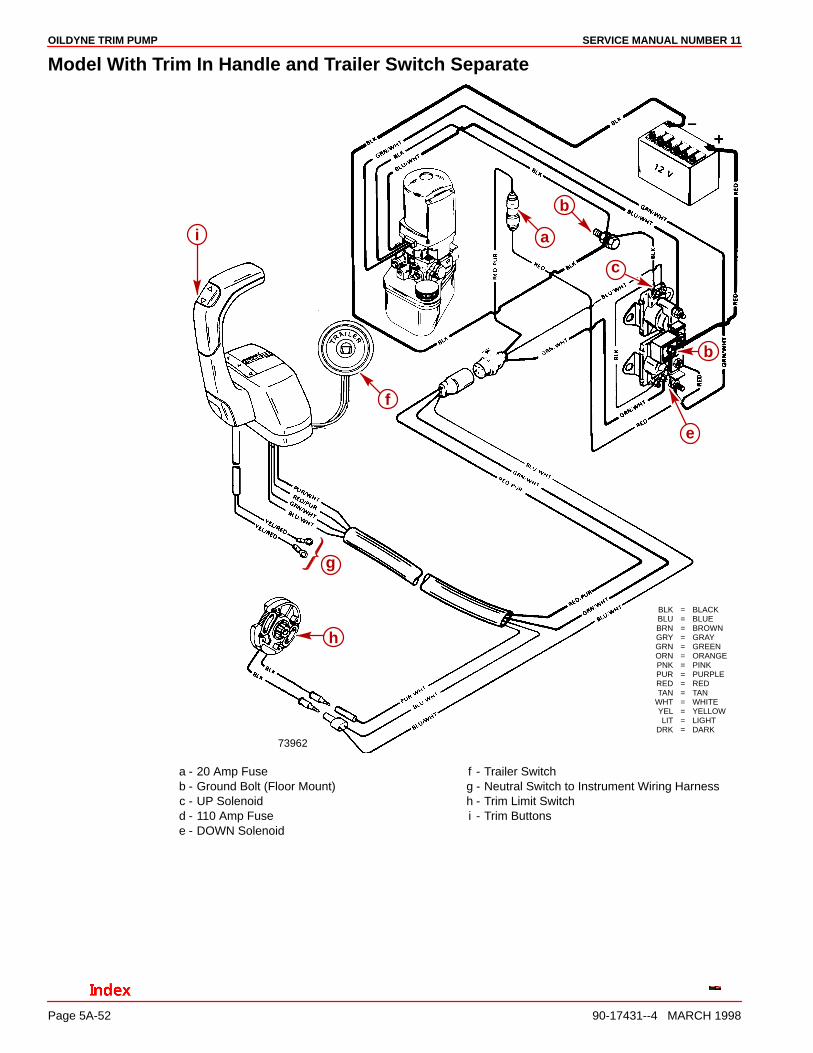
Model With Trim In Handle and Trailer Switch Separate
73962
BLK = BLACKBLU = BLUEBRN = BROWNGRY = GRAYGRN = GREENORN = ORANGEPNK = PINKPUR = PURPLERED = REDTAN = TAN
WHT = WHITEYEL = YELLOWLIT = LIGHT
DRK = DARK
b
a
c
b
e
f
g
h
i
a - 20 Amp Fuseb - Ground Bolt (Floor Mount)c - UP Solenoidd - 110 Amp Fusee - DOWN Solenoid
f - Trailer Switchg - Neutral Switch to Instrument Wiring Harnessh - Trim Limit Switchi - Trim Buttons