oildyne 550 series hydraulic power units - phtruck.com prior to installing and operating the oildyne...
TRANSCRIPT
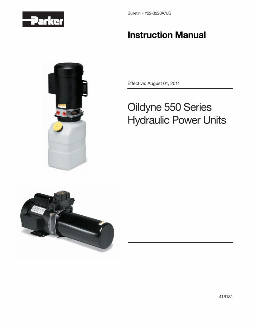
Oildyne 550 Series Hydraulic Power Units
Bulletin HY22-3220A/US
Instruction Manual
Effective: August 01, 2011
416181

2
Bulletin HY22-3220A/US Instruction Manual550 Series Hydraulic Power UnitsContents
Parker HannifinOildyne Division
FAILURE OR IMPROPER SELECTION OR IMPROPER USE OF THE PRODUCTS DESCRIBED HEREIN OR RELATED ITEMS CAN CAUSE DEATH, PERSONAL INJURY AND PROPERTY DAMAGE.
This document and other information from Parker-Hannifin Corporation, its subsidiaries and authorized distributors provide product or system options for further investigation by users having technical expertise. The user, through its own analysis and testing, is solely responsible for making the final selection of the system and components and assuring that all performance, endurance, maintenance, safety and warning requirements of the application are met. The user must analyze all aspects of the application, follow applicable industry standards, and follow the information concerning the product in the current product catalog and in any other materials provided from Parker or its subsidiaries or authorized distributors.
To the extent that Parker or its subsidiaries or authorized distributors provide component or system options based upon data or specifications provided by the user, the user is responsible for determining that such data and specifications are suitable and sufficient for all applications and reasonably foreseeable uses of the components or systems.
Offer of SalePlease contact your Parker representation for a detailed ’Offer of Sale’.
WARNING – USER RESPONSIBILITY
Table of Contents PageIntroduction 3Explanation of Warning Labels 3Description 3Preparation for Use 9Installation 9Start-Up Procedures 10Special Tools 11Safe Operating Procedures 11Operation 14Maintenance 14Recommended Spare Parts 17Troubleshooting 17Appendix 18Declaration of Conformity 19
1. Name & address of manufacturer 2. WARNING - see page 3 3. WARNING - see page 3 4. CE Mark (if applicable) 5. Year of product manufacture (if CE marked) 6. Product type 7. Part number 8. Unique identifier/serial number 9. Pressure 10. Flow rate 11. Motor voltage 12. Motor rated watts 13. Motor rated horsepower 14. Motor Amperage draw 15. Motor phase 16. Motor Hz
New Hope, MN 55428 USA
555 646608 102345678A
999 9999 9.99 9.99
XXX/XXX X.XX XX/XX XX/XXXXXX W HP A Hz
bar( psi)
VAC
Parker Hannifin - Oildyne Division
5520 Hwy 169 North
GPMLPM
11
Ф
New Hope, MN 55428 USA
555 646608 102345678A
W HP A Hz
bar( psi)
VAC
Parker Hannifin - Oildyne Division
5520 Hwy 169 North
GPMLPM
11
Ф
How to read the label on your 550 Series Power Unit

3
Bulletin HY22-3220A/US Instruction Manual550 Series Hydraulic Power UnitsIntroduction and Description
Parker HannifinOildyne Division
IntroductionThis manual provides descriptive operation and maintenance instructions for 550 Series Power Units manufactured by the Parker Hannifin Corporation, Oildyne Division. Any additional information may be obtained from Parker by referencing the unit part number stamped on the product label or by contacting your local authorized Parker Distributor.
Some of the Information in this manual may not apply to all power units. Information about custom units may require service and application information from other sources.
Warning This Instruction Manual should be read in its entirety and understood prior to installing and operating the Oildyne 550 Series Hydraulic Power Units.
It is imperative that personnel involved in the installation, service, and operation of the Oildyne units be familiar with how the equipment is to be used. They should be aware of the limitations of the system and its component parts, and have knowledge of good hydraulic practices in terms of safety, installation, and maintenance.
Explanation of Warning LabelsThe following labels will be used in this Instruction Manual and on all applicable Oildyne products.
DescriptionThe 550 Series Hydraulic Power Unit consists of an AC electric motor, fixed displacement gear pump, relief valve and reservoir with options for different circuit types incorporating NG6/D03 valves or 2 position/2 way cartridge valves. The gear pump is driven through a coupling located between the electric motor drive shaft and the pump drive shaft.
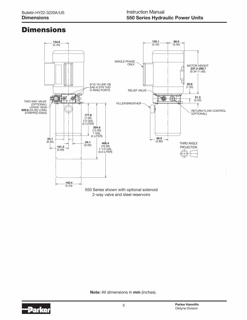
For dimensional drawings please see pages 4 to 6.
Two basic versions are available, either with SAE-6 (9/16-18) ports for the P and T connections, or with JIC-6 male extension tube fittings for use with the NG6/D03 version of the adapter.
For hydraulic schematics, please see pages 7 and 8.
The life expectancy of Parker Oildyne power units is directly tied to the frequency of use, the product in which it is incorporated and the application.
Shipping weights for the 550 Series Power Units range from 14.5 kg (36 lbs) to 50 kg (110 lbs).
The 550 Series Power Units are intended to be used in a variety of applications, specified by the customer, where pressurized hydraulic fluid is needed to move an actuator(s), charge an accumulator(s) or supply test equipment.
Pressure Capability (depends on pump/motor combination):• Upto207bar(3000psi)maximum
Flow Output (depends on pump/motor combination):• At1725rpm:.95–5.6lpm(.25–1.5gpm)• At3450rpm:1.9–11.4lpm(.5–3gpm)
Motor Specifications:• .37–2.2kW(.5–3HP)• 56Cwithbase• TEFC
Voltages (standard motors are 60 Hz):• Singlephase:115/208-230VAC• Threephase:208-230/460VAC50 Hz motors are available upon request.
Acceptable Fluids:• StandardAutomaticTransmissionFluid(ATF)• Mostmineralbasedhydraulicfluids
Viscosity range: 32-64 cSt (150-300 SSU) at 38°C (100°F) Please contact Parker Oildyne to discuss any alternate fluids.
Parker Oildyne takes no responsibility if unapproved alternative fluids are used.
Temperature Ranges:Operating: -7 to 60°C (+20 to 140°F)Storage: -10 to 60°C (+14 to 140°F)
550 Series Power Units should be installed indoors in a clean environment.
550 Series Power Units are designed for a continuous duty. However, do not operate the power unit with pump flow going over the relief valve for any length of time; this creates excessive heat. It is recommended that for any applications requiring a maintained pressure, a circuit be selected which incorporates a load holding check valve(s). Examples of these circuits would be the D1, using the Manapak double pilot operated check valves, or a two position/two way cartridge valve with included check valve.
There may be hydraulic liquid under pressure. Do not open unit or break pipe connections until hydraulic pressure has
been released.
Be careful; take precautions; examine instructions before operation.
4
Bulletin HY22-3220A/US Instruction Manual550 Series Hydraulic Power UnitsDimensions
Parker HannifinOildyne Division
Dimensions
1/2 GAL(2 LITER)
191.87.55( )
1 GAL
251.59.90( )
1-1/2 GAL
311.112.25( )
2-1/2 GAL
430.516.95( )
24.10.95( )
24.10.95( )
158.96.25( )
134.6(5.30)
TP
9/16-18 UNF-2BSAE-6 STR THD O-RING PORTS
215.98.50( )
231.99.13( )
25.81.02( )
51.32.02( )
MOTOR HEIGHT237.2-299.7(9.34-11.80)
88.93.50( )
87.43.44( )
171.56.75( )
135.1(5.32)
SINGLE PHASEONLY
FILLER/BREATHER
101.6-169.1(4.00-6.50)
65.02.56( )
Ø182.1 MAX(7.17)
165.16.50( )
76.23.00( )
62.02.44( )
62.02.44( )
4X 8.6 (.34) SLOT
(4 LITER)
(5.6 LITER)
(9.5 LITER)
Note: All dimensions in mm (inches).
THIRD ANGLEPROJECTION
550 Series shown with P and T ports and plastic reservoir
Motor foot dimensions are common to all 550 Series electric motors
Note: When mounted in the horizontal configurationthe 21/2 gallon plastic reservoir must be supported.
5
Bulletin HY22-3220A/US Instruction Manual550 Series Hydraulic Power Units
Note: When mounted in the horizontal configurationthe 21/2 gallon plastic reservoir must be supported.
Dimensions
Dimensions
THIRD ANGLEPROJECTION
177.8(7.00)
1/2 GAL(2 LITER)
134.6(5.30)
24.1(0.95)
TWO WAY VALVE(OPTIONAL)
LEADS 18GA609.6 (24.00) LONG
STRIPPED ENDS
9/16-18 UNF-2BSAE-6 STR THDO-RING PORTS
P T
304.8(12.00)1 GAL
(4 LITER)
406.4(16.00)
1-1/2 GAL(5.6 LITER)
101.3(3.99)
24.1(0.95)
140.4(5.53)
MOTOR HEIGHT237.2-299.7(9.34-11.80)
SINGLE PHASEONLY
FILLER/BREATHER
RELIEF VALVE
RETURN FLOW CONTROL(OPTIONAL)
135.1(5.32)
88.9(3.50)
25.8(1.02)
51.3(2.02)
98.0(3.86)
Note: All dimensions in mm (inches).
550 Series shown with optional solenoid 2-way valve and steel reservoirs
THIRD ANGLEPROJECTION
Parker HannifinOildyne Division

6
Bulletin HY22-3220A/US Instruction Manual550 Series Hydraulic Power UnitsDimensions
Dimensions
Note: All dimensions in mm (inches).
THIRD ANGLEPROJECTION
Parker HannifinOildyne Division
4X Ø
RESERVOIR MNT HOLES
9.5.38( )
387.415.25( )
36214.25( )
50.82.00( )
34.91.38( ) 34.9
1.38( )
50.82.00(
254(10.00)
) 304.8(12.00)
25410.00( )
25.81.02( )
Ø171.56.75( )
136.75.38( )
304.812.00( )
598.823.58( )
311.312.26( )
51.32.02( )
131.85.19( )
63.62.51( )
58.62.31( )
231.69.12( )
66.82.63( ) 82.6
3.25( )
39.91.57( )93.5
3.68( )
215.98.50( )
1817.13( )
NOTE1 DIMENSIONS ARE REFERENCE ONLY
GAUGE PORT LOCATIONSAE-6 STR THD O-RING PORT
9/16-18 UNF-2B
2X 9/16-18 UNF-2A
PORT BPORT A
FLARE TUBE END (JIC-6)
FILLER/BREATHER
550 Series shown with 19 liter (5 gallon) steel reservoir and NG6/D03 valves
7
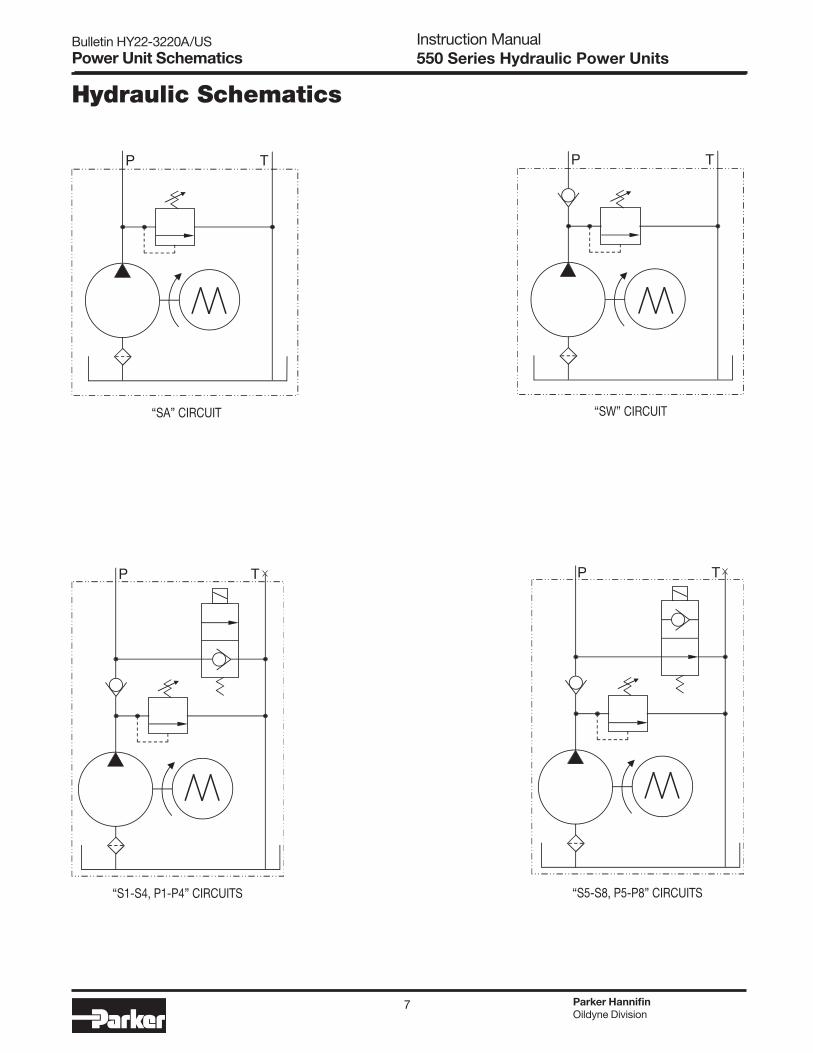
Bulletin HY22-3220A/US Instruction Manual550 Series Hydraulic Power UnitsPower Unit Schematics
Hydraulic Schematics
P T P T
P T P T
“SA” CIRCUIT “SW” CIRCUIT
“S1-S4, P1-P4” CIRCUITS “S5-S8, P5-P8” CIRCUITS
Parker HannifinOildyne Division

8
Bulletin HY22-3220A/US Instruction Manual550 Series Hydraulic Power UnitsPower Unit Schematics
Parker HannifinOildyne Division
P TP T
A B
P T
A B
A B
P T
“S1-S4, P1-P4” CIRCUITS WITH PRESSURE COMPENSATED FLOW
CONTROL F1 OR F2
“S5-S8, P5-P8” CIRCUITS WITH PRESSURE COMPENSATED FLOW
CONTROL F1 OR F2
“D0” CIRCUIT (D03 VALVE TO BE SELECTED) “D1” CIRCUIT INCLUDES MANAPAK DUAL P0 CHECK VALVE (D03 VALVE TO BE SELECTED)
A B
P TCLOSED CENTER
A B
P TOPEN CENTER
A B
P T
A B
P T
FLOAT CENTER
TANDEM CENTER
A B
P TSINGLE SOLENOID

9
Bulletin HY22-3220A/US Instruction Manual550 Series Hydraulic Power UnitsInstallation
Suitable applications for the 550 Series Power Units would be those whose requirements fall within the operating parameters given above.
Some examples of abnormal uses of this unit would include:• Useofunitwithhigherpressurethanthatforwhichitwas
rated• Userequiringcontinuousrunningofthepumpflowoverthe
pressure relief valve• Usewithhigherorlowervoltagethanrequiredforoptimal
use• Useinamountingorientationotherthanthatforwhichitwas
designed• Useoffluidsnotrecommendedforuse
Parker Hannifin Corporation takes no responsibility for safety of any unit if it is not used for the intended purposes detailed in this Instruction Manual.
Preparation for Use
Unpacking and Checking All units were carefully packed, in containers or boxes, and may or may not be on skids. In any case, do not remove anything from the skid or any packaging until it has been carefully checked for damage that may have occurred in transit. Report all damage immediately to the carrier and send a copy to the vendor.
All open ports on the power unit were plugged at the factory to prevent the entry of contamination. These plugs must not be removed until just before piping connections are made to the unit.
Storage If the unit is not going to be installed immediately, it should be stored indoors, covered with waterproof sheet, and all open ports kept plugged. If long term storage is expected (6 months or more) we recommend filling the reservoir completely with clean hydraulic fluid to prevent the entry of moisture.
Removing from packagingThe mass of 550 Series Power Units is unequally distributed in the assembly. The electric motors are the ‘heavy ends’ of the power units with the standard motors alone weighing between 8.3 kg (18.2 lbs) and 22 kg (48.4 lbs). It is strongly recommended that two people carry and move these power units. The exception is the 550 Series Power Unit using the 19 liter (5 gallon) rectangular steel reservoir. These are assembled with the electric motor above the reservoir. 550 Series Power Units with the 19 liter (5 gallon) rectangular steel reservoir should be removed from the skid by wrapping a heavy duty nylon strap around the base of the motor mounting feet. This strap should be firmly secured to the lift truck forks when unit is lifted.
Installation
Locating Power Unit The unit should preferably be installed indoors in a clean, dry environment with an ambient temperature of 15 to 38°C (60 to 100°F).
Parker Oildyne products should not be installed where they are at risk of objects falling from overhead or where there is any risk of impact with external objects.
Mounting the power unitThe majority of 550 Series Power Units are complete assemblies. A small portion is created without the electric motors, allowing the customer to purchase and install alternate motors. There is a ‘C-face’ kit available, Oildyne part number 775679, which allows a standard ‘56C with base’ motor to be mounted to the 550 Series. This kit includes a spacer plate, shaftadapterwithsetscrew,threadedstudsandnuts–allthecomponents needed to mount the motor to the power unit. See the Appendix on page 18 for installation instructions using this C face kit.
550 Series Power Units are assembled for mounting horizontally (ports or D03 valve facing UP) or vertically (motor above the reservoir), except for power units using the 19 liter (5 gallon) reservoir, which are designed only for vertical installation (motor above the reservoir).
For port locations see pages 4 - 6.
Mount the power unit securely through the provided slots in the motor foot. See page 4 for the motor foot details. Power units with the 19 liter (5 gallon) reservoir will use the reservoir base flanges to mount to the customer determined location. See page 6 for reservoir mounting flange details. Mounting bolt torque values will be determined by the type of fastener selected by the customer. It is strongly recommended that the surface to which the power unit is mounted is bonded to earth to provide proper grounding in the event of a lightning strike.
Electrical Service Connections Connect the motor to the power source following good practices as outlined in the national electric codes and any local codes which may apply. Verify that the available voltage is the same as the voltage identified on the label. Most AC motors have dual voltage ratings, so verify that the leads in the conduit box have been connected together as defined on the motor nameplate to match the facility power source available. Ensure the wiring connections will provide clockwise motor rotation, when looking at the fan end.
Standard NEMA motor connections are shown here:Single phase - 115/208/230 VAC
1 3 5 2 4 8
LINE LINE
1 Ø, Low Voltage
TAPE LINE
2 3 5 4 81
LINE
1 Ø, High Voltage
Three phase - 230/460 VACIf the 3 phase connection shown results in a counter clockwise rotation (from the fan end), interchange any two of the three L1, L2, L3 connections to reverse the motor rotation.
3 Ø, Low Voltage
TAPEL 3
4 5 63 9
L 1
1 7 2 8
L 2
3 Ø, High Voltage1
L 1
2
L 2
3
L 3
4 7
TAPE TAPE
5 8
TAPE
6 9
Customer supplied controls will include motor starters and valve operators (for NG6/D03 and solenoid cartridge valves).
Supply and Return Connections 550 Series Power Units incorporating an NG6/D03 valve surface, regardless of the valve being supplied by Oildyne or not, will include two JIC-6 (9/16-18) extensions fittings onto which the A and B actuator control connections can be made. Power units incorporating the P and T ports have two SAE-6 (9/16-18) female o-ring type ports to accept customer fittings.
Parker HannifinOildyne Division

10
Bulletin HY22-3220A/US Instruction Manual550 Series Hydraulic Power UnitsStart-Up Procedures
In circuits types using solenoid cartridge valves, the T ports will be blocked by Oildyne with an SAE-6 plug.
Fluid connectors and conductors installed by the customer should be selected based on an acceptable safety margin for the maximum pressure required in the application. 550 Series Power Units are capable of producing up to 207 bar (3000 psi).
Complete all necessary interconnecting piping to the power unit. The line sizes should be determined based on oil flow, operating pressure and allowable pressure drop between the power unit and actuator.
One of the key ingredients for good service and long life from a hydraulic system is cleanliness. Because most dirt infiltrates a hydraulic system during installation, we recommend the following:
a) All open ports on the power unit, cylinders, etc. must remain plugged with tape or plastic plugs until just before the hydraulic connections are made.
b) All interconnecting tubing, pipe, or hose should be clean, and free of rust, scale and dirt. The ends of all connectors should be plugged until just before they are to be installed in the system.
c) All openings in the reservoir such as the filler breather or access end covers holes must remain closed during installation.
Hydraulic Fluids Follow all vendor-supplied instructions for safe handling, use and disposal of the fluid selected for operation in this power unit.
It is strongly recommended that the customer have available the MSDS for the fluid chosen for use in the 550 Series Power Unit. Follow all instructions should the fluid be spilled or come in contact with an operator.
It is critical that the reservoir be filled with an approved fluid prior to startup of the power unit. Any system failures due to improper fluids being used or operating without the reservoir being full of an approved fluid will result in voiding the warranty.
The reservoir must be filled with clean fluid through the filler cap on the reservoir. The type of fluid must be compatible with the seals used on the power unit, and must comply with the recommendations of the manufacturers of the component parts. Acceptable fluids include standard Automatic Transmission Fluid (ATF) and most mineral based hydraulic fluids with viscosities between 32 cSt (150 SSU) and 64 cSt (300 SSU) at 38°C (100°F). For fluids other than these, please contact Oildyne Division with the details. If users wish to use alternative oil, hydraulic fluid or ATF, they are warned to check that they have the same properties as those recommended. Parker Oildyne takes no responsibility if alternatives are used.
Reservoir Filling The cylindrical steel reservoirs have filler/breathers with a 3/8-18 NPT thread. The head of the breather is circular allowing the breathertoberemovedandinstalledbyhandonly–notoolsare necessary. The 19 liter (5 gallon) reservoir breather is also operablebyhand–notoolsarenecessary.
The rectangular plastic reservoirs have a filler breather which isa‘pushin/pullout’design,installablebyhand–notoolsarerequired.
Reservoir volumes: Maximum fill at 7 mm (.25 in) below filler for all (vertical and horizontal) but 19 liter (5 gallon) reservoir, which is 25.4 mm (1 in) below filler.
Vertical Mount (motor above reservoir)
Total Volume Usable Volume
Code Liter Gallon Liter Gallon
05 2.0 .51 1.1 .30
10 3.9 1.0 3.0 .80
15 5.5 1.4 4.5 1.2
06 3.0 .80 1.0 .26
11 4.8 1.3 3.0 .79
16 6.8 1.8 4.9 1.3
26 10.3 2.7 8.4 2.2
50 23.4 6.2 19 5.0
Horizontal Mount (motor foot down)
Total Volume Usable Volume
Code Liter Gallon Liter Gallon
05 2.5 .66 1.6 .44
10 4.5 1.2 2.9 .77
15 6.0 1.6 3.9 1.0
06 3.8 1.0 2.5 .67
11 5.3 1.4 3.3 .88
16 6.4 1.7 4.2 1.1
26 9.4 2.5 6.0 1.6
50 Vertical mounting only
The cleanliness of the fluid going into the reservoir is very important. In some cases, even new oil out of the drum is not adequate. We recommend that any fluid being transferred into the reservoir be done with the transfer pump with a 10 micron filter installed. A Parker-manufactured filter cart is available for this purpose.
Start-Up Procedures
Circuit breakers/fusesFuses and circuit breaker protection must conform to national electrical codes and local codes and practices. The following table shows the Full Load Current (FLA) of the standard (60 Hz) motors used in the 550 Series Power Units.
SINGLE PHASE MOTORS 115V 230V
MODEL RPM WATTS HP FLA FLA
TC 1725 375 0.50 8.2 4.1
TE 1725 560 0.75 9.4 4.7
TJ 1725 750 1.00 13.6 6.8
TL 1725 1125 1.50 17.0 8.5
TV 1725 1500 2.00 19.0 9.5
TM 3450 375 0.50 6.2 3.1
TN 3450 560 0.75 9.0 4.5
TP 3450 750 1.00 12.4 6.2
TQ 3450 1125 1.50 16.0 8.0
TS 3450 1500 2.00 21.4 10.7
Parker HannifinOildyne Division
11
Bulletin HY22-3220A/US Instruction Manual550 Series Hydraulic Power UnitsSafe Operating Procedures
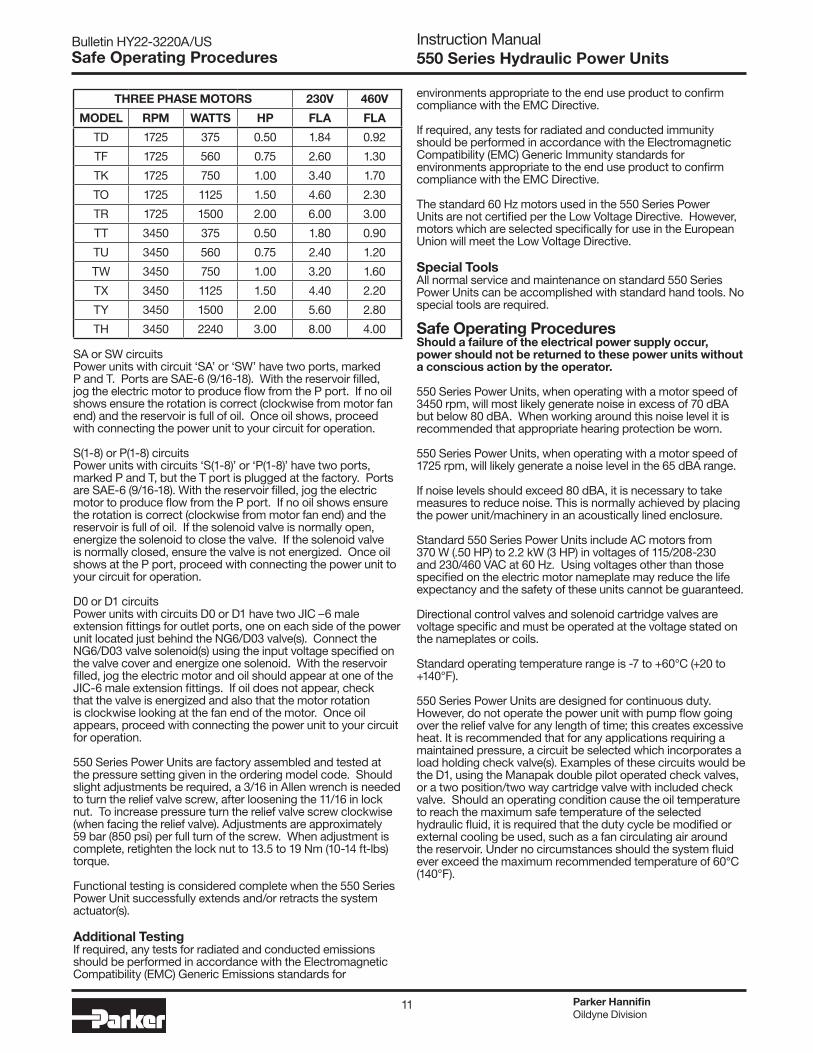
THREE PHASE MOTORS 230V 460V
MODEL RPM WATTS HP FLA FLA
TD 1725 375 0.50 1.84 0.92
TF 1725 560 0.75 2.60 1.30
TK 1725 750 1.00 3.40 1.70
TO 1725 1125 1.50 4.60 2.30
TR 1725 1500 2.00 6.00 3.00
TT 3450 375 0.50 1.80 0.90
TU 3450 560 0.75 2.40 1.20
TW 3450 750 1.00 3.20 1.60
TX 3450 1125 1.50 4.40 2.20
TY 3450 1500 2.00 5.60 2.80
TH 3450 2240 3.00 8.00 4.00
SA or SW circuitsPower units with circuit ‘SA’ or ‘SW’ have two ports, marked P and T. Ports are SAE-6 (9/16-18). With the reservoir filled, jog the electric motor to produce flow from the P port. If no oil shows ensure the rotation is correct (clockwise from motor fan end) and the reservoir is full of oil. Once oil shows, proceed with connecting the power unit to your circuit for operation.
S(1-8) or P(1-8) circuitsPower units with circuits ‘S(1-8)’ or ‘P(1-8)’ have two ports, marked P and T, but the T port is plugged at the factory. Ports are SAE-6 (9/16-18). With the reservoir filled, jog the electric motor to produce flow from the P port. If no oil shows ensure the rotation is correct (clockwise from motor fan end) and the reservoir is full of oil. If the solenoid valve is normally open, energize the solenoid to close the valve. If the solenoid valve is normally closed, ensure the valve is not energized. Once oil shows at the P port, proceed with connecting the power unit to your circuit for operation.
D0 or D1 circuitsPowerunitswithcircuitsD0orD1havetwoJIC–6maleextension fittings for outlet ports, one on each side of the power unit located just behind the NG6/D03 valve(s). Connect the NG6/D03 valve solenoid(s) using the input voltage specified on the valve cover and energize one solenoid. With the reservoir filled, jog the electric motor and oil should appear at one of the JIC-6 male extension fittings. If oil does not appear, check that the valve is energized and also that the motor rotation is clockwise looking at the fan end of the motor. Once oil appears, proceed with connecting the power unit to your circuit for operation.
550 Series Power Units are factory assembled and tested at the pressure setting given in the ordering model code. Should slight adjustments be required, a 3/16 in Allen wrench is needed to turn the relief valve screw, after loosening the 11/16 in lock nut. To increase pressure turn the relief valve screw clockwise (when facing the relief valve). Adjustments are approximately 59 bar (850 psi) per full turn of the screw. When adjustment is complete, retighten the lock nut to 13.5 to 19 Nm (10-14 ft-lbs) torque.
Functional testing is considered complete when the 550 Series Power Unit successfully extends and/or retracts the system actuator(s).
Additional TestingIf required, any tests for radiated and conducted emissions should be performed in accordance with the Electromagnetic Compatibility (EMC) Generic Emissions standards for
environments appropriate to the end use product to confirm compliance with the EMC Directive.
If required, any tests for radiated and conducted immunity should be performed in accordance with the Electromagnetic Compatibility (EMC) Generic Immunity standards for environments appropriate to the end use product to confirm compliance with the EMC Directive.
The standard 60 Hz motors used in the 550 Series Power Units are not certified per the Low Voltage Directive. However, motors which are selected specifically for use in the European Union will meet the Low Voltage Directive.
Special Tools All normal service and maintenance on standard 550 Series Power Units can be accomplished with standard hand tools. No special tools are required.
Safe Operating ProceduresShould a failure of the electrical power supply occur, power should not be returned to these power units without a conscious action by the operator.
550 Series Power Units, when operating with a motor speed of 3450 rpm, will most likely generate noise in excess of 70 dBA but below 80 dBA. When working around this noise level it is recommended that appropriate hearing protection be worn.
550 Series Power Units, when operating with a motor speed of 1725 rpm, will likely generate a noise level in the 65 dBA range.
If noise levels should exceed 80 dBA, it is necessary to take measures to reduce noise. This is normally achieved by placing the power unit/machinery in an acoustically lined enclosure.
Standard 550 Series Power Units include AC motors from 370 W (.50 HP) to 2.2 kW (3 HP) in voltages of 115/208-230 and 230/460 VAC at 60 Hz. Using voltages other than those specified on the electric motor nameplate may reduce the life expectancy and the safety of these units cannot be guaranteed.
Directional control valves and solenoid cartridge valves are voltage specific and must be operated at the voltage stated on the nameplates or coils.
Standard operating temperature range is -7 to +60°C (+20 to +140°F).
550 Series Power Units are designed for continuous duty. However, do not operate the power unit with pump flow going over the relief valve for any length of time; this creates excessive heat. It is recommended that for any applications requiring a maintained pressure, a circuit be selected which incorporates a load holding check valve(s). Examples of these circuits would be the D1, using the Manapak double pilot operated check valves, or a two position/two way cartridge valve with included check valve. Should an operating condition cause the oil temperature to reach the maximum safe temperature of the selected hydraulic fluid, it is required that the duty cycle be modified or external cooling be used, such as a fan circulating air around the reservoir. Under no circumstances should the system fluid ever exceed the maximum recommended temperature of 60°C (140°F).
Parker HannifinOildyne Division

12
Bulletin HY22-3220A/US Instruction Manual550 Series Hydraulic Power Units
Standard Product Model Code
4-WAY VALVE (ALL D03 SIZE)CODE DESCRIPTIONNNN No 4-Way Valve Included01Y Closed Center, 120 VAC, Conduit Connectors01T Closed Center, 240 VAC, Conduit Connectors01K Closed Center, 12 VDC, Conduit Connectors01J Closed Center, 24 VDC, Conduit Connectors02Y Open Center, 120 VAC, Conduit Connectors02T Open Center, 240 VAC, Conduit Connectors02K Open Center, 12 VDC, Conduit Connectors02J Open Center, 24 VDC, Conduit Connectors07Y Float Center, 120 VAC, Conduit Connectors07T Float Center, 240 VAC, Conduit Connectors07K Float Center, 12 VDC, Conduit Connectors07J Float Center, 24 VDC, Conduit Connectors08Y Tandem Center, 120 VAC, Conduit Connectors08T Tandem Center, 240 VAC, Conduit Connectors08K Tandem Center, 12 VDC, Conduit Connectors08J Tandem Center, 24 VDC, Conduit Connectors30Y Single Solenoid, 120 VAC, Conduit Connector30T Single Solenoid, 240 VAC, Conduit Connector30K Single Solenoid, 12 VDC, Conduit Connector30J Single Solenoid, 24 VDC, Conduit Connector
Y01 Closed Center, 120 VAC, Hirschmann w/out PlugsT01 Closed Center, 240 VAC, Hirschmann w/out PlugsK01 Closed Center, 12 VDC, Hirschmann w/out PlugsJ01 Closed Center, 24 VDC, Hirschmann w/out PlugsY02 Open Center, 120 VAC, Hirschmann w/out PlugsT02 Open Center, 240 VAC, Hirschmann w/out PlugsK02 Open Center, 12 VDC, Hirschmann w/out PlugsJ02 Open Center, 24 VDC, Hirschmann w/out PlugsY07 Float Center, 120 VAC, Hirschmann w/out PlugsT07 Float Center, 240 VAC, Hirschmann w/out PlugsK07 Float Center, 12 VDC, Hirschmann w/out PlugsJ07 Float Center, 24 VDC, Hirschmann w/out PlugsY08 Tandem Center, 120 VAC, Hirschmann w/out PlugsT08 Tandem Center, 240 VAC, Hirschmann w/out PlugsK08 Tandem Center, 12 VDC, Hirschmann w/out PlugsJ08 Tandem Center, 24 VDC, Hirschmann w/out PlugsY30 Single Solenoid, 120 VAC, Hirschmann w/out PlugT30 Single Solenoid, 240 VAC, Hirschmann w/out PlugK30 Single Solenoid, 12 VDC, Hirschmann w/out PlugJ30 Single Solenoid, 24 VDC, Hirschmann w/out Plug
550
MOTOR SELECTION - TEFCSingle Phase = 115/230 VAC, 60 HZThree Phase = 230/460 VAC, 60 HZCODE HP RPM PHASE TC .50 1725 Single TD .50 1725 Three TM .50 3450 Single TT .50 3450 Three TE .75 1725 Single TF .75 1725 Three TN .75 3450 Single TU .75 3450 Three TJ 1.0 1725 Single TK 1.0 1725 Three TP 1.0 3450 Single TW 1.0 3450 Three TL 1.5 1725 Single TO 1.5 1725 Three TQ 1.5 3450 Single TX 1.5 3450 Three TV 2.0 1725 Single TR 2.0 1725 Three TS 2.0 3450 Single TY 2.0 3450 Three TH 3.0 3450 Three
PUMP SIZECODE DISPLACEMENT
RESERVOIRCODE VOLUME
CIRCUITCODE DESCRIPTION D0 D03 Pad & Extension Fittings D1 D03 Pad with Dual PO Check Manifold (Manapak)
(for use with D03 Directional Control Valves) SA Standard Pressure & Tank Ports SW Std P & T Ports with Outlet Port Check Valve
Two Position Two Way Cartridge ValvesFollowing circuits include outlet port check valve:
S1 12 VDC, Normally Closed, Conduit Connector S2 24 VDC, Normally Closed, Conduit Connector S3 120 VAC, Normally Closed, Conduit Connector S4 240 VAC, Normally Closed, Conduit Connector S5 12 VDC, Normally Open, Conduit Connector S6 24 VDC, Normally Open, Conduit Connector S7 120 VAC, Normally Open, Conduit Connector S8 240 VAC, Normally Open, Conduit Connector
P1 12 VDC, Normally Closed, DIN Connector P2 24 VDC, Normally Closed, DIN Connector P3 120 VAC, Normally Closed, DIN Connector P4 240 VAC, Normally Closed, DIN Connector P5 12 VDC, Normally Open, DIN Connector P6 24 VDC, Normally Open, DIN Connector P7 120 VAC, Normally Open, DIN Connector P8 240 VAC, Normally Open, DIN Connector
FLOW CONTROL(for use with Cartridge Valves)CODE DESCRIPTION NN None (use with D0 and D1 circuits) HP None (use with all other circuits) F1 Press. Comp., .5 to 1.0 GPM F2 Press. Comp., 1.0 to 2.0 GPM
RV SETTINGIn multiples of 100 psiExamples04 = 400 psi12 = 1200 psi29 = 2900 psi
550 POWER UNIT- includes relief valve
Note: 19 liter (5 gallon)steel reservoir can be mounted vertically only. All others are vertical and horizontal ready
04 0.66 cc/rev (.04 in3/rev)07 1.15 cc/rev (.07 in3/rev)10 1.64 cc/rev (.10 in3/rev)14 2.29 cc/rev (.14 in3/rev)17 2.79 cc/rev (.17 in3/rev)20 3.28 cc/rev (.20 in3/rev)
05 2 Liter 0.5 Gallon Steel10 4 Liter 1.0 Gallon Steel15 6 Liter 1.5 Gallon Steel50 19 Liter 5.0 Gallon Steel06 2 Liter 0.5 Gallon Plastic11 4 Liter 1.0 Gallon Plastic16 6 Liter 1.5 Gallon Plastic26 10 Liter 2.5 Gallon Plastic
Standard Product Model Code
Parker HannifinOildyne Division

13
Bulletin HY22-3220A/US Instruction Manual550 Series Hydraulic Power Units
4-WAY VALVE (ALL D03 SIZE)CODE DESCRIPTION (For use only with Circuit Codes D0 and D1)NNN No 4-Way Valve Included01Y Closed Center, 120 VAC, Conduit Connectors01T Closed Center, 240 VAC, Conduit Connectors01K Closed Center, 12 VDC, Conduit Connectors01J Closed Center, 24 VDC, Conduit Connectors02Y Open Center, 120 VAC, Conduit Connectors02T Open Center, 240 VAC, Conduit Connectors02K Open Center, 12 VDC, Conduit Connectors02J Open Center, 24 VDC, Conduit Connectors07Y Float Center, 120 VAC, Conduit Connectors07T Float Center, 240 VAC, Conduit Connectors07K Float Center, 12 VDC, Conduit Connectors07J Float Center, 24 VDC, Conduit Connectors08Y Tandem Center, 120 VAC, Conduit Connectors08T Tandem Center, 240 VAC, Conduit Connectors08K Tandem Center, 12 VDC, Conduit Connectors08J Tandem Center, 24 VDC, Conduit Connectors30Y Single Solenoid, 120 VAC, Conduit Connector30T Single Solenoid, 240 VAC, Conduit Connector30K Single Solenoid, 12 VDC, Conduit Connector30J Single Solenoid, 24 VDC, Conduit Connector
Y01 Closed Center, 120 VAC, Hirschmann w/out PlugsT01 Closed Center, 240 VAC, Hirschmann w/out PlugsK01 Closed Center, 12 VDC, Hirschmann w/out PlugsJ01 Closed Center, 24 VDC, Hirschmann w/out PlugsY02 Open Center, 120 VAC, Hirschmann w/out PlugsT02 Open Center, 240 VAC, Hirschmann w/out PlugsK02 Open Center, 12 VDC, Hirschmann w/out PlugsJ02 Open Center, 24 VDC, Hirschmann w/out PlugsY07 Float Center, 120 VAC, Hirschmann w/out PlugsT07 Float Center, 240 VAC, Hirschmann w/out PlugsK07 Float Center, 12 VDC, Hirschmann w/out PlugsJ07 Float Center, 24 VDC, Hirschmann w/out PlugsY08 Tandem Center, 120 VAC, Hirschmann w/out PlugsT08 Tandem Center, 240 VAC, Hirschmann w/out PlugsK08 Tandem Center, 12 VDC, Hirschmann w/out PlugsJ08 Tandem Center, 24 VDC, Hirschmann w/out PlugsY30 Single Solenoid, 120 VAC, Hirschmann w/out PlugT30 Single Solenoid, 240 VAC, Hirschmann w/out PlugK30 Single Solenoid, 12 VDC, Hirschmann w/out PlugJ30 Single Solenoid, 24 VDC, Hirschmann w/out Plug
550
MOTOR SELECTION - TEFCSingle Phase = 115/230 VAC, 60 HZThree Phase = 230/460 VAC, 60 HZCODE HP RPM PHASE TC .50 1725 Single TD .50 1725 Three TM .50 3450 Single TT .50 3450 Three TE .75 1725 Single TF .75 1725 Three TN .75 3450 Single TU .75 3450 Three TJ 1.0 1725 Single TK 1.0 1725 Three TP 1.0 3450 Single TW 1.0 3450 Three TL 1.5 1725 Single TO 1.5 1725 Three TQ 1.5 3450 Single TX 1.5 3450 Three TV 2.0 1725 Single TR 2.0 1725 Three TS 2.0 3450 Single TY 2.0 3450 Three
PUMP SIZECODE DISPLACEMENT 04 .04 CIPR 07 .07 CIPR 10 .10 CIPR 14 .14 CIPR 17 .17 CIPR 20 .20 CIPR
RESERVOIRCODE VOLUME 05 0.5 Gal. Steel 10 1.0 Gal. Steel 15 1.5 Gal. Steel 50 5.0 Gal. Steel 06 0.5 Gal. Plastic 11 1.0 Gal. Plastic 16 1.5 Gal. Plastic 26 2.5 Gal. Plastic
CIRCUITCODE DESCRIPTION D0 D03 Pad & Extension Fittings D1 D03 Pad with Dual PO Check Manifold (Manapak)
(for use with D03 Directional Control Valves) SA Standard Pressure & Tank Ports SW Std P & T Ports with Outlet Port Check Valve
Two Position Two Way Cartridge ValvesFollowing circuits include outlet port check valve:
S1 12 VDC, Normally Closed, Conduit Connector S2 24 VDC, Normally Closed, Conduit Connector S3 120 VAC, Normally Closed, Conduit Connector S4 240 VAC, Normally Closed, Conduit Connector S5 12 VDC, Normally Open, Conduit Connector S6 24 VDC, Normally Open, Conduit Connector S7 120 VAC, Normally Open, Conduit Connector S8 240 VAC, Normally Open, Conduit Connector
P1 12 VDC, Normally Closed, DIN Connector P2 24 VDC, Normally Closed, DIN Connector P3 120 VAC, Normally Closed, DIN Connector P4 240 VAC, Normally Closed, DIN Connector P5 12 VDC, Normally Open, DIN Connector P6 24 VDC, Normally Open, DIN Connector P7 120 VAC, Normally Open, DIN Connector P8 240 VAC, Normally Open, DIN Connector
FLOW CONTROL(for use with Cartridge Valves)CODE DESCRIPTION NN None (use with D0 and D1 circuits) HP None (use with all other circuits) F1 Pressure Compensated, 2 to 4 LPM (.5 to 1.0 GPM) F2 Pressure Compensated, 4 to 8 LPM (1.0 to 2.0 GPM)
RV SETTINGIn multiples of 100 psiExamples04 = 400 psi12 = 1200 psi29 = 2900 psi
550 POWER UNIT- includes relief valve
Note: 5 gal. steel reservoir can be mounted vertically only. All others are vertical and horizontal ready
Standard Product Model Code
Parker HannifinOildyne Division

14
Bulletin HY22-3220A/US Instruction Manual550 Series Hydraulic Power UnitsOperation and Maintenance
Removal from service
There may be hydraulic liquid under pressure. Do not open unit or break pipe connections until hydraulic pressure has
been released.
If, for some reason, the power unit must be removed from service, follow these instructions:1) Wear protective eye gear.2) Remove electrical power from the motor and solenoid valve
(if applicable).3) Mechanically hold/block the actuator load to prevent its
movement once pressure is relieved in the fluid conductors.4) Only after the load is mechanically held in place, put a
rag around the A or B port fitting and loosen the port connection. The rag will absorb an oil leakage as any locked pressure is relieved. Then put a rag around the other port connection and loosen the port connection.
5) Immediately cap the fluid conductor ends and the power unit ports to prevent the introduction of contaminants until the power unit is reconnected.
6) When reinstalling the power unit, follow all the procedures and startup instructions on page 10.
Operation Suitable lighting requirements for operation of this unit are the responsibility of installing manufacturer.
The 550 Series Power Units are assembled and tested according to the specific model codes ordered. See page 15 for performance graphs which provide the expected flows of the available pump sizes at 1725 RPM and 3450 RPM at a variety of pressures.
MaintenanceMaintenance should only be conducted when units are disconnected from the power supply, depressurized and removed from service.
Reservoirs -Maintain oil level at all times. The oil should be checked after the first 100 hours and verified that the class of oil meets the requirements of the pump being used. Change the oil every 1000 to 2000 hours depending on the application and operation environment.
Cylindrical Steel and Composite ReservoirsTo remove the fluid from the cylindrical steel and composite reservoirs, it is recommended to remove the filler cap and use a siphon to remove the oil. Dispose of, or recycle the used fluid according to local regulations. Once the fluid is removed, an examination of the suction strainer is suggested. To access the strainer, the reservoir must be removed. To remove the cylindrical steel and composite plastic reservoirs, loosen and remove the four screws holding the reservoir flange to the power unit adapter. These screws require an 8 mm (5/16 in) wrench or socket.
In horizontal applications, place absorbent paper or towels under the reservoir flange area to catch any remaining fluid as the reservoir is removed from the power unit adapter. Dispose of any oil-soaked materials according to local regulations.
19 liter (5 gallon) reservoirTo remove the fluid from this reservoir, there are two drain plugs provided, one on each end. These plugs require an adjustable wrench or 15 mm (9/16 in) open end wrench to remove (and replace). Another option is to remove the electric motor and adapter assembly from the reservoir by removing the four each 5/16 in hex head screws holding the adapter to the reservoir cover. Use a siphon to remove the fluid from this reservoir. Dispose of, or recycle the used fluid according to local regulations. This method will allow for examination of the suction strainer.
Suctionstrainer–Itisrecommendedthatatthesameintervalsat which the reservoir fluid is changed, the suction strainer be examined for any conditions restricting the free flow of fluid through it. If the strainer appears restricted at all, it is recommended that the strainer be replaced. The strainer is Oildyne part number 410542. The strainer is hand threaded onto a plastic elbow. Turn the strainer counter-clockwise to remove then install a new strainer by turning the strainer clockwise onto the elbow threads until it is tight against the elbow hex.
Cylindrical Steel and Composite ReservoirsOnce the suction strainer has been installed, replace the reservoir using the same four hex head screws. Ensure the filler port on the reservoir is oriented to face UP. Torque the
Parker HannifinOildyne Division

15
Bulletin HY22-3220A/US Instruction Manual550 Series Hydraulic Power UnitsPerformance Data
Parker HannifinOildyne Division
550 Power Units @ 1725 RPM
17
14
20
07
04
10
(500) (3000)(2500)(2000)(1500)(1000)
(50)
(100)
(150)
(200)
(250)
(300)
(350)
0.8
1.6
2.5
3.3
4.1
4.9
5.7
(400)6.6
Out
put F
low
- lp
m (c
ipm
)
0 34 69 103 138 172 207
Operating Pressure - bar (psi)
0
550 Power Units @ 3450 RPM
17
14
20
07
04
10
(500) (3000)(2500)(2000)(1500)(1000)
(100)
(200)
(300)
(400)
(500)
(600)
(700)
1.6
3.3
4.9
6.6
8.2
9.8
11.5
(800)13.1
Out
put F
low
- lp
m (c
ipm
)
0 34 69 103 138 172 207
Operating Pressure - bar (psi)
0
Motor Horsepower Recommendations at Flow/Pressure
Pump Size
Nominal GPM Pressure Bar (PSI)
@1725 @345034
(500)69
(1000)103
(1500)138
(2000)172
(2500)207
(3000)
04 ¼ .50 HP .50 HP .50 HP .50 HP .50 HP .50 HP
04 ½ .50 HP .50 HP .50 HP .75 HP 1.0 HP 1.0 HP
07 ½ .50 HP .50 HP .50 HP .75 HP 1.0 HP 1.0 HP
07 1 .50 HP .75 HP 1.0 HP 1.5 HP 2.0 HP 2.0 HP
10 ¾ .50 HP .50 HP .75 HP 1.0 HP 1.5 HP 1.5 HP
10 1 ½ .75 HP 1.0 HP 1.5 HP 2.0 HP 3.0 HP 3.0 HP
14 1 .50 HP .75 HP 1.0 HP 1.5 HP 2.0 HP 2.0 HP
14 2 1.0 HP 1.5 HP 2.0 HP 3.0 HP
17 1 ¼ .50 HP 1.0 HP 1.5 HP 2.0 HP 2.0 HP
17 2 ½ 1.0 HP 2.0 HP 3.0 HP
20 1 ½ .50 HP 1.0 HP 1.5 HP 2.0 HP
20 3 1.0 HP 2.0 HP 3.0 HP
Note: Performance data is for reference only
Performance data based on ATF @ 21°C (70°F)

16
Bulletin HY22-3220A/US Instruction Manual550 Series Hydraulic Power Units
are warned to check that they have the same properties as those recommended. Parker Oildyne takes no responsibility if alternatives are used.
Maintenance Suggestions1. Never return to the system any fluid which has leaked out.2. Always keep the supply of fresh fluid covered tightly.3. Use clean containers, hoses, and funnels when filling the
reservoir. Use of a filter cart when adding oil is highly recommended.
4. Use common sense precautions to prevent entry of dirt into components which have been temporarily removed from the circuit.
5. Make sure that the breather/filler on the reservoir is properly fastened.
6. Do not run the system unless the normally provided suction strainer is in place.
7. Make certain that the fluid used in the system is of a type recommended by Parker Oildyne.
8. Parker offers an oil sampling kit which can be used to ascertain the condition of the system fluid.
Maintaining Proper Oil Temperature Hot oil in your equipment’s hydraulic system is one of the primary causes of poor operation, component failure and downtime. Here are some tips on maintaining proper oil temperature.
1. The oil in your hydraulic system was designed for operation within a specified temperature range. You may be able to run it at hotter temperatures for short periods of time, intermittently, without adverse effects. If run continuously with oil that is too hot, equipment will operate poorly causing key component failure and machine downtime.
2. “Hot oil” is a relative term. In most cases, 49°C (120°F) at the reservoir is considered an ideal operating temperature. Always take an oil temperature reading at the reservoir, not at a component or any of the piping.
3. Keep your equipment clean. A thick layer of dirt acts as insulation. It will prevent the hydraulic system from getting rid of heat.
4. On hot days, and in hot climates, check and change the oil more frequently. Be sure to use an oil recommended for hot weather operation by the equipment manufacturer or oil supplier.
Measuring Oil Temperature If your machine does not have a reservoir thermometer, use the “palm test”. First check the tank with your fingertip; if it is not too hot to touch, place your palm on the tank. You should be able to hold it there without discomfort if the oil temperature is about 54°C (130°F) or below.
Isolating Trouble-Spots To determine which components are “running hot” and overheating the oil, touch the outlet fittings and lines at the valves, pumps and motors. If the oil temperature is normal going into a component but hot coming out, that could be one of the potential problem areas.
A sticking valve can cause excessive heat. If a spool does not return promptly to the neutral position, the pump flow will be dumping continuously. This builds up heat rapidly.
If a relief valve is set too low, part of the oil will be dumped across the valve with every cycle. This too, generates excessive heat. Even when all valves are set properly, they may not be
four screws to 5.6 Nm (50 in-lbs). Refill the reservoir with an approved fluid prior to startup of the power unit. Any system failures due to improper fluids being used or operating without the reservoir being full of an approved fluid will result in voiding the warranty.
19 liter (5 gallon) reservoirOnce the suction strainer has been installed, remount the motor and pump combination on the reservoir cover, ensuring the reservoir gasket is still in place, positioned so the four holes on the corners are aligned with the four adapter mounting screw holes. Torque these four screws to 5.6 Nm (50 in-lbs). Refill the reservoir with an approved fluid prior to startup of the power unit. Any system failures due to improper fluids being used or operating without the reservoir being full of an approved fluid will result in voiding the warranty.
The reservoir must be filled with clean fluid through the filler cap on the reservoir. The type of fluid must be compatible with the seals used on the power unit, and must comply with the recommendations of the manufacturers of the component parts. Acceptable fluids include standard Automatic Transmission Fluid (ATF) and most mineral based hydraulic fluids with viscosities between 32 cSt (150 SSU) and 64 cSt (300 SSU) at 38°C (100°F). For fluids other than these, contact Parker Oildyne with the details. If users wish to use alternative oil, hydraulic fluid or ATF, they are warned to check that they have the same properties as those recommended. Parker Oildyne takes no responsibility if alternatives are used.
Reservoir volumes: Maximum fill at 7 mm (.25 in) below filler for all (vertical and horizontal) but 19 liter (5 gallon) reservoir, which is 25.4 mm (1 in) below filler.
Vertical Mount (motor above reservoir)Total Volume Usable Volume
Code Liter Gallon Liter Gallon05 2.0 .51 1.1 .3010 3.9 1.0 3.0 .8015 5.5 1.4 4.5 1.206 3.0 .80 1.0 .2611 4.8 1.3 3.0 .7916 6.8 1.8 4.9 1.326 10.3 2.7 8.4 2.250 23.4 6.2 19 5.0
Horizontal Mount (motor foot down)Total Volume Usable Volume
Code Liter Gallon Liter Gallon05 2.5 .66 1.6 .4410 4.5 1.2 2.9 .7715 6.0 1.6 3.9 1.006 3.8 1.0 2.5 .6711 5.3 1.4 3.3 .8816 6.4 1.7 4.2 1.126 9.4 2.5 6.0 1.650 Vertical mounting only
It is recommended that all fluid being transferred into the reservoir be done by a transfer pump with a 10 micron filter installed. A Parker-manufactured filter cart is available for this purpose.
Hydraulic Fluids Dispose of, or recycle the used fluid according to local regulations.
If users wish to use alternative oil, hydraulic fluid or ATF, they
Maintenance
Parker HannifinOildyne Division
17
Bulletin HY22-3220A/US Instruction Manual550 Series Hydraulic Power UnitsTroubleshooting
operating well because of worn orifices or seals. Always remove and check the hot components first.
Check Oil Samples Periodically Periodically checking oil temperature and siphoning an oil sample from the reservoir, comparing it with a sample of new, clean oil, is good preventive maintenance.
Oil that has been running too hot will look darker and feel thinner than new oil. It will also smell burned. Normally it will contain more contaminants, because hot oil leads to accelerated wear of component parts.
Recommended Spare Parts The only recommended maintenance component is the suction
Parker HannifinOildyne Division
FAILURE MODE CAUSE(S) CORRECTIVE ACTIONMotor will not run No power to the motor Ensure proper voltage is available at motor
Motor is wired incorrectly Wire the motor per the Installation instructions
Motor runs, but no flow Reservoir does not have enough fluid Fill the reservoir per the Installation instructions with an approved fluid
Motor rotation is not clockwise from fan end Single phase motors: wire per the Installation instructionsThree phase: interchange any two of the three power leads
Two position/two way valve is not closed If a normally open valve, energize to close. If a normally closed valve, de-energize coil
D03/NG6 valve is not shifted from center position Energize one of the valve solenoids
Low flow Incorrect pump was selected or installed Contact your distributor for rework instructions
Relief valve is set too low for application allowing bypass
Increase the relief valve setting ensuring the flow and pressure output are still within the electric motor’s capability
Reservoir overflows on cylinder retract
Reservoir is too full. Filling the reservoir with the actuators extended will cause an overflow condition when actuators are retracted
Ensure that, with the system full of oil and the actuators fully retracted, the reservoir is at the full condition
Motor gets hot/high current draw
Motor is not wired per the Installation instructions Ensure proper voltage is available at motor
Wire the motor per the Installation instructions
Will not build pressure Reservoir does not have enough fluid Fill the reservoir per the Installation instructions with an approved fluid
Motor rotation is not clockwise from fan end Single phase motors: wire per the Installation instructionsThree phase: interchange any two of the three power leads
Relief valve is set too low for application allowing bypass
Increase the relief valve setting ensuring the flow and pressure output are still within the electric motor’s capability
Will not hold pressure Circuit type selected will not hold pressure Ensure the model code calls out the D1 circuit, the SW circuit or an S_ or P_ circuit. Only these circuits are designed to hold pressure
Two position/two way valve is not closed If a normally open valve, energize to close. If a normally closed valve, de-energize coil
D03/NG6 valve selected without the Manapak check valve block
D03/NG6 directional valves are not designed to hold pressure. Contact your Parker Oildyne distributor to purchase a Manapak check valve manifold
Leaks at fittings Hose ends/fitting adapters are not the correct type for the 550 Series ports
For the D0 and D1 circuits, the power unit includes JIC-6 male extension fittings. For all other circuits, the power unit has SAE-6 male ports
Fittings are not tightened properly Ensure all fittings are properly tightened
Actuator will not move both ways Valve coils are not energized properly Ensure the directional valve coils are operating properly
Relief valve is set too low for application allowing bypass
Increase the relief valve setting ensuring the flow and pressure output are still within the electric motor’s capability
strainer, Oildyne part number 410542. See the Maintenance section on page 14 for instructions on replacing the suction strainer.
Be aware of risk of hazards if poor quality replacement parts are used or are obtained from an unauthorized source. Using non-Parker supplied components will void the warranty.
Conclusive Unit FailureIf the operation of the unit cannot be restored after attempts at the troubleshooting suggestions listed below, please contact your local Parker distributor or the Oildyne Division directly to arrange for warranty replacement/repair if within the warranty period.
Troubleshooting
18
Bulletin HY22-3220A/US Instruction Manual550 Series Hydraulic Power Units
FAILURE MODE CAUSE(S) CORRECTIVE ACTIONDirty fluid Filler/breather cap not installed on reservoir Install the proper filler/breather cap on the reservoir.
Drain dirty fluid and replace with clean fluid
Fluid lines not properly covered while servicing power unit
Once service is complete and all lines are properly connected, drain dirty fluid and replace with clean fluid
Pump strainer is plugged, damaged or missing Install a new pump suction strainer
Foaming fluid Fluid line is broken allowing air into system Locate and replace broken fluid lines. Allow air in fluid to settle out before operating system
Fluid contaminated with foreign matter Eliminate source of foreign matter, drain dirty fluid and replace with clean fluid
System overheats Power unit runs at relief valve setting for extended period of time
Install switches or load holding valve as needed to prevent the pump from running over the relief valve for extended period of time
Reservoir sized too small Contact your Parker Oildyne distributor for a larger reservoir
Fluid conductors are too small for system flow rates
Increase the fluid conductor sizes to reduce fluid velocities
Foreign matter sources in system
Sealing compound (pipe dope, TeflonTM tape, etc.) allowed inside fittings
Use a reduced amount of sealing compound to ensure it doesn’t overflow into wetted areas
System pressure exceeds design limits of seals and gaskets
Either reduce the operating pressure or select components capable of the high pressures
Humanelement–componentsnotprotectedduring service
During service, ensure all components are protected from external contamination
Solenoid coil failures Voltage too low Voltage to solenoids must be per solenoid specification to avoid burning out coil
Voltage too high Voltage to solenoids must be per solenoid specification to avoid burning out coil
Both solenoids are energized concurrently Only one solenoid can be energized at any given time to prevent coil burnout. Ensure voltage signals are interlocked to prevent this condition
Mechanical damage to leads Replace all damaged wires and/or plugs
Voltage signal loss Long leads can cause improper voltage signal at coils and erratic signal. Check with voltmeter
Troubleshooting
Parker HannifinOildyne Division
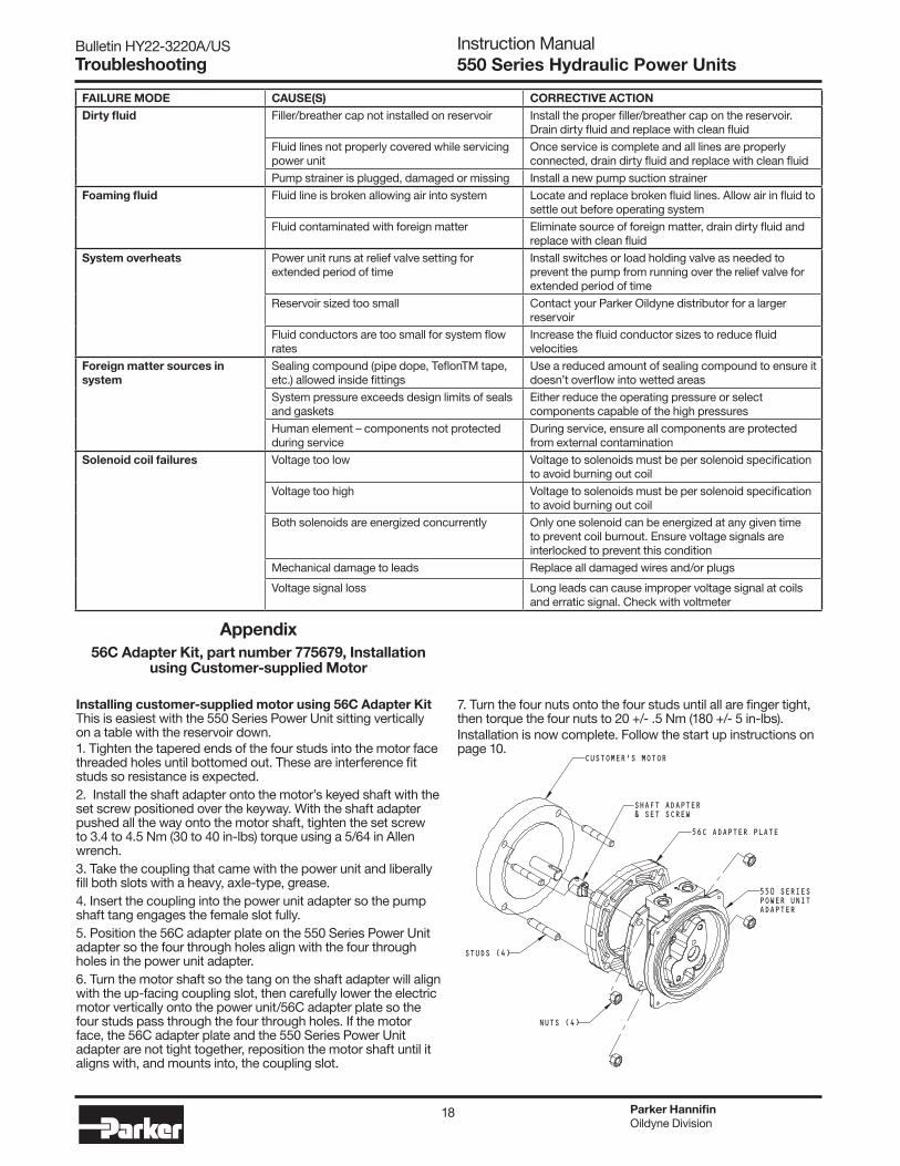
Appendix56C Adapter Kit, part number 775679, Installation
using Customer-supplied Motor
Installing customer-supplied motor using 56C Adapter KitThis is easiest with the 550 Series Power Unit sitting vertically on a table with the reservoir down.1. Tighten the tapered ends of the four studs into the motor face threaded holes until bottomed out. These are interference fit studs so resistance is expected.2. Install the shaft adapter onto the motor’s keyed shaft with the set screw positioned over the keyway. With the shaft adapter pushed all the way onto the motor shaft, tighten the set screw to 3.4 to 4.5 Nm (30 to 40 in-lbs) torque using a 5/64 in Allen wrench. 3. Take the coupling that came with the power unit and liberally fill both slots with a heavy, axle-type, grease.4. Insert the coupling into the power unit adapter so the pump shaft tang engages the female slot fully.5. Position the 56C adapter plate on the 550 Series Power Unit adapter so the four through holes align with the four through holes in the power unit adapter.6. Turn the motor shaft so the tang on the shaft adapter will align with the up-facing coupling slot, then carefully lower the electric motor vertically onto the power unit/56C adapter plate so the four studs pass through the four through holes. If the motor face, the 56C adapter plate and the 550 Series Power Unit adapter are not tight together, reposition the motor shaft until it aligns with, and mounts into, the coupling slot.
7. Turn the four nuts onto the four studs until all are finger tight, then torque the four nuts to 20 +/- .5 Nm (180 +/- 5 in-lbs).Installation is now complete. Follow the start up instructions on page 10.
SHAFT ADAPTER& SET SCREW
CUSTOMER'S MOTOR
56C ADAPTER PLATE
550 SERIESPOWER UNITADAPTER
NUTS (4)
STUDS (4)
19
Bulletin HY22-3220A/US Instruction Manual550 Series Hydraulic Power Units
EC Declaration of Incorporation.
Manufacturer’s Name: Parker Hannifin Corporation
Manufacturer’s Address: Oildyne Division
5520 Highway 169 North
New Hope, MN 55428 USA
Declare that the partially complete machinery described below conforms to applicable health and safety requirements of Part 1 of Annex 1 of Machinery Directive 2006/42/EC taking full account of requirements for pressure equipment. This partly completed machinery must not be put into service until the machinery into which it is to be incorporated has been declared in conformity with the provisions of the Machinery Directive. Confidential technical documentation has been compiled as described in Part B of Annex VII of Machinery Directive 2006/42/EC and is available to European national authorities on written request. If a request is received documentation will be transmitted either electronically or by post.
Description: Oildyne 550 Series Power Units
Model Number: As Applies
Sizes: All
Serial Number: All
The following standards have either been referred to or complied with in part or in full as relevant:
ENISO 12100 – 2 Machinery Safety - Basic concepts, general principles for design – Part 2: Technical principles and specifications.
EN13849 Machinery Safety - Safety Related Parts of Control Systems – Part 1: General Principles for Design.
EN 982:1996 Machinery Safety - Safety requirements for fluid power systems and their components – Hydraulics.
Full Name of responsible person Van Mancuso
Place of signing:
Parker Hannifin Corporation Oildyne Division Position General Manager, Oildyne Division 5520 Highway 169 North New Hope, MN 55428 USA
Signature Date March 17, 2011
Full Name of Authorized European Representative Stephen Fryer
Place of signing:
Parker Hannifin Ltd. Cylinder Division Europe Position General Manager, Cylinder Division Europe 6 Greycaine Road, Watford, Hertfordshire. WD24 7QA, UK
Signature Date March 17, 2011
Declaration of Incorporation
Parker HannifinOildyne Division
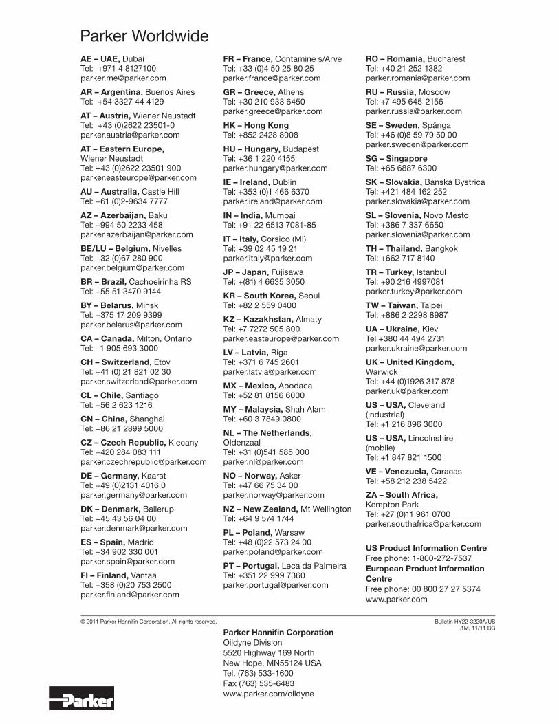
AE – UAE, Dubai Tel: +971 4 8127100 [email protected]
AR – Argentina, Buenos Aires Tel: +54 3327 44 4129
AT – Austria, Wiener Neustadt Tel: +43 (0)2622 23501-0 [email protected]
AT – Eastern Europe, Wiener Neustadt Tel: +43 (0)2622 23501 900 [email protected]
AU – Australia, Castle Hill Tel: +61 (0)2-9634 7777
AZ – Azerbaijan, Baku Tel: +994 50 2233 458 [email protected]
BE/LU – Belgium, Nivelles Tel: +32 (0)67 280 900 [email protected]
BR – Brazil, Cachoeirinha RS Tel: +55 51 3470 9144
BY – Belarus, Minsk Tel: +375 17 209 9399 [email protected]
CA – Canada, Milton, Ontario Tel: +1 905 693 3000
CH – Switzerland, Etoy Tel: +41 (0) 21 821 02 30 [email protected]
CL – Chile, Santiago Tel: +56 2 623 1216
CN – China, Shanghai Tel: +86 21 2899 5000
CZ – Czech Republic, Klecany Tel: +420 284 083 111 [email protected]
DE – Germany, Kaarst Tel: +49 (0)2131 4016 0 [email protected]
DK – Denmark, Ballerup Tel: +45 43 56 04 00 [email protected]
ES – Spain, Madrid Tel: +34 902 330 001 [email protected]
FI – Finland, Vantaa Tel: +358 (0)20 753 2500 [email protected]
FR – France, Contamine s/Arve Tel: +33 (0)4 50 25 80 25 [email protected]
GR – Greece, Athens Tel: +30 210 933 6450 [email protected]
HK – Hong Kong Tel: +852 2428 8008
HU – Hungary, Budapest Tel: +36 1 220 4155 [email protected]
IE – Ireland, Dublin Tel: +353 (0)1 466 6370 [email protected]
IN – India, Mumbai Tel: +91 22 6513 7081-85
IT – Italy, Corsico (MI) Tel: +39 02 45 19 21 [email protected]
JP – Japan, Fujisawa Tel: +(81) 4 6635 3050
KR – South Korea, Seoul Tel: +82 2 559 0400
KZ – Kazakhstan, Almaty Tel: +7 7272 505 800 [email protected]
LV – Latvia, Riga Tel: +371 6 745 2601 [email protected]
MX – Mexico, Apodaca Tel: +52 81 8156 6000
MY – Malaysia, Shah Alam Tel: +60 3 7849 0800
NL – The Netherlands, Oldenzaal Tel: +31 (0)541 585 000 [email protected]
NO – Norway, Asker Tel: +47 66 75 34 00 [email protected]
NZ – New Zealand, Mt Wellington Tel: +64 9 574 1744
PL – Poland, Warsaw Tel: +48 (0)22 573 24 00 [email protected]
PT – Portugal, Leca da Palmeira Tel: +351 22 999 7360 [email protected]
Parker WorldwideRO – Romania, Bucharest Tel: +40 21 252 1382 [email protected]
RU – Russia, Moscow Tel: +7 495 645-2156 [email protected]
SE – Sweden, Spånga Tel: +46 (0)8 59 79 50 00 [email protected]
SG – Singapore Tel: +65 6887 6300
SK – Slovakia, Banská Bystrica Tel: +421 484 162 252 [email protected]
SL – Slovenia, Novo Mesto Tel: +386 7 337 6650 [email protected]
TH – Thailand, Bangkok Tel: +662 717 8140
TR – Turkey, Istanbul Tel: +90 216 4997081 [email protected]
TW – Taiwan, Taipei Tel: +886 2 2298 8987
UA – Ukraine, Kiev Tel +380 44 494 2731 [email protected]
UK – United Kingdom, Warwick Tel: +44 (0)1926 317 878 [email protected]
US – USA, Cleveland (industrial) Tel: +1 216 896 3000
US – USA, Lincolnshire (mobile) Tel: +1 847 821 1500
VE – Venezuela, Caracas Tel: +58 212 238 5422
ZA – South Africa, Kempton Park Tel: +27 (0)11 961 0700 [email protected]
US Product Information CentreFree phone: 1-800-272-7537European Product Information CentreFree phone: 00 800 27 27 5374www.parker.com
Bulletin HY22-3220A/US.1M, 11/11 BG
© 2011 Parker Hannifin Corporation. All rights reserved.
Parker Hannifin CorporationOildyne Division5520 Highway 169 NorthNew Hope, MN55124 USATel. (763) 533-1600Fax (763) 535-6483www.parker.com/oildyne