on increased vzn suspension performanceson increased vzn suspension performances adrian-ioan...
TRANSCRIPT

On Increased VZN Suspension Performances ADRIAN-IOAN NICULESCU, DAN DUMITRIU Institute of Solid Mechanics – Romanian Academy
Str. Constantin Mille, nr. 15, 010141 Bucharest ROMANIA
[email protected] http://www.imsar.ro
Abstract: - The paper present the increased suspension performances assured by VZN shock absorbers, comparative with standard ones, based on a theoretical evaluation of the pitch behaviour and a 2D, ½ car model simulation. The results present evolution of the front and rear body displacements, accelerations, forces in stop bumpers, piston displacement, for both VZN and standard shock absorbers. The new self-adjustable VZN shock absorber confers improved flexibility to adjust each stroke part according to the specific needs, providing a larger range of damping coefficients, function of the relative piston position in the cylinder. Both on rebound and compression, the VZN damping coefficients have low values at the beginning of the strokes, becoming medium at the middle of the strokes and high and very high to its end. So it gives a good correlation between loads and damping coefficients, decreasing body vertical acceleration and thus increasing the comfort, reducing speed at stroke ends and so the forces in stopper bumpers and thus increasing axles, body and passengers’ protection, and increasing stability at pitch. Key-Words: - self-adjustable VZN, shock absorber, half-car 2D model, Matlab/Simulink, pitch, stability, comfort, body protection, axle protection, passenger protection. 1 Introduction The proposed self-adjustable shock absorber is called VZN, this acronym coming from Variable Zeta Nnecessary, for well moving in all road and load conditions, where zeta represents the relative damping, which is adjusted automatically, stepwise, according to the piston position. The VZN shock absorber consists of an inner cylinder having sideways valves or metering holes, inside a slidably piston moving. For VZN principle understanding, Fig.1 presents from left to right three situations, with the piston in start, middle and ending position, on compression stroke. The number of active metering holes decreases, so the fluid flows out with increased resistance, generating increasing damping coefficients with the stroke. Thus, for VZN the damping force is adjusted stepwise, as function of the instantaneous piston position, i.e., both on rebound and compression the damping coefficients have: low values at the beginning of the strokes (the hydraulic fluid flows out through all the metering holes); moderate values at the middle of the strokes, for a good tradeoff between comfort and wheel adherence (the hydraulic fluid flows out through half of the metering holes); high values in the working area between middle and end strokes, for better adherence and good axle movement brake (the fluid flows out through quarter of the metering holes); and very high values at the end of the strokes, for better body and axles protection (the fluid flows out
through only one or two metering holes). The VZN principle is presented in Fig. 1 for compression stroke. On rebound stroke the evolution is changed, the active area being in blue color and filling area in red color.
Fig.1. The VZN principle, illustrated for compression stroke, with the distributed metering holes placed sideways.
WSEAS TRANSACTIONS on SYSTEMS and CONTROL Adrian-Ioan Niculescu and Dan Dumitriu
ISSN: 1991-8763 676 Issue 8, Volume 3, August 2008

Realized without electronics or mechanisms, this new concept of shock absorbers VZN, has been granted with European Patent EP 1190184 [6] and Romanian Patent 118546 [7]. The design of this passive dynamic VZN shock absorber was so far optimized considering the piston position on full loads and unloads and for end strokes movement high breaking. In what concerns the quality/price ratio, the passive dynamic VZN shock absorber realizes an improved and better adapted damping than a standard suspension, for more or less the same price and technological simplicity. Previous papers [1],[3]-[5] presented the behavior of a suspension using the new self-adjustable VZN shock absorber, simulated on a quarter-car vehicle model. In this paper, the Matlab/Simulink simulation of the VZN behavior is extended from the quarter-car model to the half-car 2D model, in order to better approach the real 3D environment. The simulations performed in this more realistic context confirm the conclusions of the previous quarter-car model simulation, showing improved comfort and adherence performances of the self-adjustable VZN shock absorber, compared with standard shock absorbers. Thus, better body stability-skyhook comportment, better protection at the stroke ends and lower RMS body accelerations were obtained using VZN suspension. Other advantages consist in decreasing lift/squat at acceleration, decreasing dive/lift at braking and decreasing pitch/roll. Ongoing test-bench experiments are performed to prove the advantages of the new self-adjustable VZN shock absorber pointed out by computer simulation. 2 On pitch theoretical consideration The suspension reaction forces equilibrate the movements given by the longitudinal forces, us the aerodynamic forces acting in the side pressure center, or inertial forces, acting in the gravity center. They can be considered like a resultant longitudinal force FL, acting at „h“ distance relative to the line of the suspension element on body attachments. Under the longitudinal forces ± FL the body rotates due to the spring deformation, the system being equilibrated by the spring reaction RFR, RRR, which increase/decrease relative to the initial situation with ΔR. The viscous forces DFR, DRR given by the front and rear shock absorbers stabilize the movement. Figs. 2-3 represent the planar pitch model, in initial situation, without longitudinal forces and in the equilibrium position in situation with longitudinal forces. Where:
W – body weight; LF – longitudinal force;
FRR –front springs reaction; α –pitch angle
RRR – rear springs reaction; a – wheel base δ –spring deformation; Sk – spring rigidity
ar 5.0=
Fig.2 – The planar pitch model without side forces
Figure 3 – The planar pitch model with side forces
Considering VZN shock absorbers having 10 identically metering holes, so damping coefficients have variation of 100 times, along the stroke.
Fig. 4 The active holes number, acting on counterclockwise rotation
WSEAS TRANSACTIONS on SYSTEMS and CONTROL Adrian-Ioan Niculescu and Dan Dumitriu
ISSN: 1991-8763 677 Issue 8, Volume 3, August 2008

At system unbalanced/redressing, the shock absorbers acts with anti-gyration/anti-redressing torques, the active metering holes according pitch angle being indicated in the Figs. 4-5, for both states. Fig. 5 The active holes number, acting on clockwise
rotation Considering the body and the pitch axle in the medium position, the front and rear sprung mass and front and rear shock absorbers identically, the number of active holes is given in Figs.6-7.
Fig. 6. The shock absorbers number of active holes acting on unbalance rotation
Fig. 7. The shock absorbers number of active holes acting on redressing rotation
The anti-gyration / anti-redressing damping coefficients and the relative torques have the values indicated in the Tab.1, for situation shown
in the Fig. 6-7, where the number in ordinate lines represents the number of active metering holes.
Tab. 1. The VZN and standard pitch damping coefficients, its
ratio and relative pitch angle
The relations are:
21
nc
c qq = nCompressio/Rebound=q (1)
holes activ ofnumber =n
=+
=+
==V
DDr
rV
DDrTc qqq RRFRqRRFR )()( 2
ϖα
α
21
211
22 )(4
)(4 n
cn
ccaccac RCRC
αα =
+=+= (2)
Para
met
ers
The holes position ][ i± ±1 ±2 ±3 ±4 ±5
),()( δα ifuf ==
2δ
± 2
3δ±
2
5δ±
2
7δ±
2
9δ±
UNBALANCEING ROTATION Un 5 4 3 2 1 2Un 25 16 9 4 1
VZNU
cα 25
1θc
161θc
9
1θc
41θc
1θc
SU
cα 36
1θc
361θc
36
1θc
361θc
36
1θc
S
VZN
U
U
cc
α
α
1.44
2.25
4
9
36
PURAE 1.44 2.25 4 9 36
REDRESSING ROTATION Rn 6 7 8 9 10 2Rn 36 49 64 81 100
VZNR
cα 36
1θc 49
1θc
641θc
81
1θc
361θc
SR
cα 36
1θc
361θc
36
1θc
361θc
36
1θc
S
VZN
R
R
cc
α
α
1
0.73
0.56
0.44
0.36
PRRAE 1 0.73 0.56 0.44 0.36
WSEAS TRANSACTIONS on SYSTEMS and CONTROL Adrian-Ioan Niculescu and Dan Dumitriu
ISSN: 1991-8763 678 Issue 8, Volume 3, August 2008

jqq VcD = ; for this case VcD qq = (3) (4)
−qc1 compression/rebound damping coefficient for one active hole
FRD - the front shock absorbers damping force
RRD the rear shock absorbers damping force
)(4 11
2
1 RC ccac +=α (4)
(5)
S
VZNS
PVZNP
PU
U
UUU c
cTTRAE
α
α== (5)
(6)
S
VZNS
PVZNP
PR
R
RRR c
cTTRAE
α
α== (6)
(7)
PURAE - relative anti-unbalance effect at pitch ; P
URAE -relative anti-redressing effect at pitch Tab. 1 −αT the pitch shock absorbers damping torque
Fig. 8. The VZN shock absorber anti-unbalancing pitch behavior, relative to the standard one
Fig. 9. The VZN shock absorber redressing at pitch behavior, relative to the standard one
The theoretical analyses show the VZN shock absorbers confer better behavior at the pitch, relative
to the standard ones, because for identically metering holes, the anti-pitch torque decrease with the square of the number of active metering holes, vary usually more 30 times. The progressive damping coefficients give by the VZN solution confers:
• An anti-unbalance torque, progressive with the pitch angle, giving pitch stability at unbalancing.
• An anti-redressing torque, regressive with the pitch angle, favoring pitch stability at redressing.
Fig. 10. The VZN shock absorber anti-pitch behavior, relative to the standard one
2 Half-Car 2D Dynamic Model Fig.2 shows the half-car 2D dynamic model [2],[8]-[9] used to study the vertical interaction between car and road, considering the pitch motion of the car. The model has 4 degrees of freedom, i.e., the vertical displacement x1 of the front of the car body (front bounce), the vertical displacement x2 of the back of the car body (rear bounce), the vertical displacement x3 of the front wheel center (front wheel hop) and the vertical displacement x4 of the rear wheel center (rear wheel hop). At time t, the vertical profile of the road (road roughness) corresponding to the front wheel is denoted by x01(t) and the road roughness corresponding to the rear wheel is denoted by x02(t). The model contains two levels of elastic and damping elements: one level between the wheels and the road, characterized by the stiffness coefficients 0k ′ and 0k ′′ of the tires and the damping coefficients 0c′ and 0c′′ of the tires; the second level between the wheels and the body (vehicle suspension), characterized by the spring rates of suspension k′ and k″ and the damping coefficients c′ and c″ of the two VZN shock absorbers (or two standard shock absorbers, as comparison variant).
Relative Anti-Unbalancing Pitch Effect
Relative Anti-Redressing
Pitch Effect
WSEAS TRANSACTIONS on SYSTEMS and CONTROL Adrian-Ioan Niculescu and Dan Dumitriu
ISSN: 1991-8763 679 Issue 8, Volume 3, August 2008

Fig.11. Half-car 2D dynamic model.
The 2D car/road vertical interaction model in Fig.11 implies the following geometrical and inertial characteristics: - the distance a between the mass center C of the sprung mass M and the point P′ located on the vertical axis passing through the front wheel center; - the distance b between the mass center C of the sprung mass M and the point P″ located on the vertical axis passing through the rear wheel center; - the wheel base A of the car (obviously A=a+b); - the front unsprung mass m′, i.e., half of the mass of the front wheels and axle; - the rear unsprung mass m″, i.e., half of the mass of the rear wheels and axle; - the mass M of the car body (sprung mass M), which normally takes values between Mempty (unloaded car case, including only seat+driver and fuel masses) and Mfull (maximum admissible car loading case); - the moment of inertia Iα of the sprung mass M with respect to the transversal axis passing through the mass center C of the sprung mass. 2.1 Car body and wheels dynamic equations The two dynamic equations of the car body, one in terms of forces and the other in terms of moments with respect to the mass center C, are:
1 2 1 3
2 4 ,bumper ,bumper
2 2
1 2 1 3
2 4 ,bumper ,bumper
( )2 2 ( )
( )2 2 ( )
c c
e e
c c
e e
Mb Max x F F k x xA Ak x x F F
M Mx x aF bF ak x xA Abk x x aF bF
α α
⎧ ′ ′′ ′+ = − − − −⎪
′′ ′ ′′− − + +⎨ ρ ρ ′ ′′ ′− + = − + −
′′ ′ ′′− − − +
⎪⎪
⎪⎪⎪⎩
(7)
where cF ′ and cF ′′ are the damping forces given by the shock absorbers (see expressions (3) and (4)),
IMα
αρ = is the radius of gyration of the sprung
mass M with respect to the transversal axis passing through its mass center C; finally ,bumbereF ′ and
,bumbereF ′′ represent the elastic striking forces when the piston hits either the rebound bumper ( ,bumber 0eF < case) or the compression bumper ( ,bumber 0eF > case), as detailed in §2.2. The two dynamic equations of the front and rear wheels are:
3 0 3 01 1 3
0 3 01 ,bumper
4 0 4 02 2 4
0 4 02 ,bumper
( ) ( ) ( )
( ) ( ) ( )
c
e
c
e
m x F c x x k x xk x x F
m x F c x x k x xk x x F
′ ′ ′ ′= − − + −⎧⎪ ′ ′− − −⎪⎨ ′′ ′′ ′′ ′′= − − + −⎪⎪ ′′ ′′− − −⎩
(8)
The second order differential equations of motion (1) and (2) can be easily transformed in a system of four first order explicit ordinary differential equations, ready to be numerically integrated by usual methods, e.g., the Runge-Kutta method. For the VZN shock absorber, the damping forces are of the form:
2,VZN VZN 1 3( )cF c x x′ ′= − , 2
,VZN VZN 2 4( )cF c x x′′ ′′= − . (9) The evolution laws of the damping coefficients VZNc′ and VZNc′′ for VZN are so far confidential. VZNc′ and
VZNc′′ increase from 0.1 [kN.s/m] up to 350 [kN.s/m]
on rebound stroke, and from 0.2 [kN.s/m] up to 600 [kN.s/m] on compression stroke, i.e., more than 3000 times between their minimum and maximum values, depending on the instantaneous piston position. For the considered standard shock absorber, the damping forces ,standardcF ′ and ,standardcF ′′ can be approximated as follows:
0.91241 3 1 3
,standard 0.40131 3 1 3
1.87 [kN], if 0
0.6975 [kN], if 0c
x x x xF
x x x x
⎧ ⋅ − − ≥⎪′ = ⎨− ⋅ − − ≤⎪⎩
,
0.91242 4
,standard 0.40132 4
1.87 [kN], on rebound
0.6975 [kN], on compr.c
x xF
x x
⎧ ⋅ −⎪′′ = ⎨− ⋅ −⎪⎩
(10)
2.2 Kinematic shock absorber model Fig.3 presents the kinematic shock absorber model, where elastic striking force on stop bumpers ,bumbereF increases linearly from 0 to -500 [daN] beginning at the touch point of rebound bumper, up to the dup distance (stroke of the rebound stop bumper), respectively decreases linearly from 0 to 1000 [daN] beginning at the touch point of the compression
WSEAS TRANSACTIONS on SYSTEMS and CONTROL Adrian-Ioan Niculescu and Dan Dumitriu
ISSN: 1991-8763 680 Issue 8, Volume 3, August 2008

bumper, down to ddown distance (stroke of the compression stop bumper). Otherwise, ,bumbereF is null. In Fig.3, l is the the full stroke, up down( + )l d d− the free stroke and d is the distance between the static middle piston position
(corresponding to empty full
2M M
M+
= ) and the static
equilibrium piston position for the current value of the sprung mass M.
Fig.12. Scheme of the shock absorber. For the front and respectively rear shock absorbers, this distance d is given by:
( )2b gd M MA k
′ = −′
, ( )2a gd M MA k
′′ = −′′
.(11)
3 Case Study and Results The considered car has the following geometrical, inertial, elastic and damping characteristics: - 1.223 [m]a = , 1.218 [m]b = , the wheel base
2.441 [m]A a b= + = ; - the front unsprung mass 31.5 [kg]m′ = , - the rear unsprung mass 30 [kg]m′′ = , - the empty and full masses of the car body
empty 0.96 [t]M = and full 1.44 [t]M = ;
- the moment of inertia 20.913 [t m ]I = ⋅α ; - shock absorber dimensions 0.236 [m]l = ,
up 0.014 [m]d = , down 0.040 [m]d = ;
- spring rates of suspension 11.37 [kN/m]k ′ = and 14.10 [kN/m]k ′′ = ;
- stiffness coefficients of the tires 0 167 [kN/m]k′ = and 0 218 [kN/m]k′′ = ,
- tires damping coefficients 016.7 [kN s / m]2
cf
′ = ⋅π
and 021.8 [kN s / m]2
cf
′′ = ⋅π
, where
1 2 3max( , , )f f f f= is the maximum frequency among the frequencies of the harmonic functions composing the considered road profile (see §3.1). The simulations are performed for a car speed of
80 [km/h]v = . 3.1 Road conditions For a better evaluation three kind of road were taken into consideration: a. A sum of three harmonic functions:
0 1 1 1 2 2 2
3 3 3
sin(2π ) sin(2π ) sin(2π ).x a f a f
a f= + + +
+ +
φ φφ
(12)
The values of the amplitudes, frequencies and phases of the three harmonic functions appearing in the expression (5) considered for the road profile, are given below in Table 2.
Table 2. Amplitudes, frequencies and phases of the excitation harmonic functions.
i Amplitude ai [m]
Frequency fi [Hz]
Phase φi [rad]
1 0.10 1 02 0.03 5 5.0815 3 0.01 10 1.2146
b. A record from a real Californian road profile, shown in Fig.10.
Fig.13. Sample of real Californian road profile.
c. A simply harmonic function
WSEAS TRANSACTIONS on SYSTEMS and CONTROL Adrian-Ioan Niculescu and Dan Dumitriu
ISSN: 1991-8763 681 Issue 8, Volume 3, August 2008
0 sin(2π )x a f= (13)
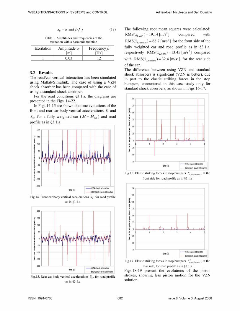
Table 1. Amplitudes and frequencies of the excitation with a harmonic function
3.2 Results The road/car vertical interaction has been simulated using Matlab/Simulink. The case of using a VZN shock absorber has been compared with the case of using a standard shock absorber. For the road conditions §3.1.a, the diagrams are presented in the Figs. 14-22. In Figs.14-15 are shown the time evolutions of the front and rear car body vertical accelerations 1x and
2x , for a fully weighted car ( fullM M= ) and road profile as in §3.1.a
Fig.14. Front car body vertical accelerations 1x , for road profile
as in §3.1.a
Fig.15. Rear car body vertical accelerations 2x , for road profile
as in §3.1.a
The following root mean squares were calculated: 2
1,VZNRMS( ) 19.14 [m/s ]x = compared with 2
1,standardRMS( ) 68.7 [m/s ]x = for the front side of the fully weighted car and road profile as in §3.1.a, respectively 2
2,VZNRMS( ) 13.45 [m/s ]x = compared with 2
2,standardRMS( ) 32.4 [m/s ]x = for the rear side of the car. The difference between using VZN and standard shock absorbers is significant (VZN is better), due in part to the elastic striking forces in the stop bumpers, encountered in this case study only for standard shock absorbers, as shown in Figs.16-17.
Fig.16. Elastic striking forces in stop bumpers ,stop bumbereF ′ , at the
front side for road profile as in §3.1.a
Fig.17. Elastic striking forces in stop bumpers ,stop bumbereF ′′ , at the
rear side, for road profile as in §3.1.a Figs.18-19 present the evolutions of the piston strokes, showing less piston motion for the VZN solution.
Excitation Amplitude ai [m]
Frequency fi [Hz]
1 0.03 12
WSEAS TRANSACTIONS on SYSTEMS and CONTROL Adrian-Ioan Niculescu and Dan Dumitriu
ISSN: 1991-8763 682 Issue 8, Volume 3, August 2008

Fig.18. Front piston strokes x13, for road profile as in §3.1.a
Fig.19. Rear piston strokes x24, for road profile as in §3.1.a
Thus, the standard deviations obtained for the piston strokes are:
13 ,VZN 4.03 [cm]x =σ compared with
13 ,standard 6.76 [cm]x =σ for the front side of the fully
weighted car and road profile as in §3.1.a, respectively
24 ,VZN 4.2 [cm]x =σ compared with
24 ,standard 5.97 [cm]x =σ for the rear side of the car
Fig.20. Front car side bounces x1, for road profile as §3.1.a
Figs.20-21 show the time evolutions of the front and rear car body vertical displacements x1 and x2..
Fig.21. Rear car side bounces x2 for road profile as in §3.1.a
Fig.22. Pitch angles of the car body, for fully weighed car and
road profile as in §3.1.a The time evolutions of the pitch angle, for a fully weighted car ( fullM M= ) and road profile as in §3.1.a, obtained by simulation using Matlab/Simulink are presented in the Fig.22. VZN shock absorber gives more 60 % pitch stability comparative to the standard shock absorber. For the road conditions §3.1.b, the simulation comparison VZN versus standard shock absorber, for a fully loaded car, performed for a real Californian road profile, shown in Fig.13. Figs.23-24 show the time evolutions of the front and rear car body vertical accelerations 1x and 2x , for a fully weighted car ( fullM M= ) and the real Californian road profile sample in Fig.10.
WSEAS TRANSACTIONS on SYSTEMS and CONTROL Adrian-Ioan Niculescu and Dan Dumitriu
ISSN: 1991-8763 683 Issue 8, Volume 3, August 2008
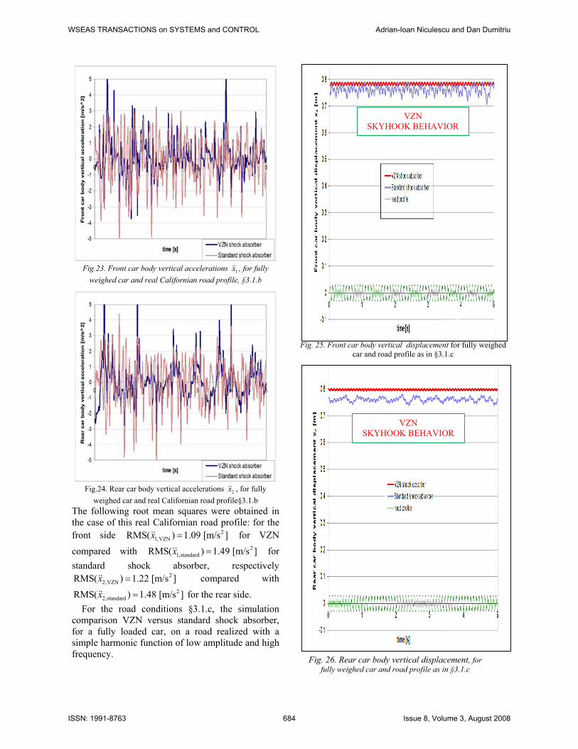
Fig.23. Front car body vertical accelerations 1x , for fully
weighed car and real Californian road profile, §3.1.b
Fig.24. Rear car body vertical accelerations 2x , for fully
weighed car and real Californian road profile§3.1.b The following root mean squares were obtained in the case of this real Californian road profile: for the front side 2
1,VZNRMS( ) 1.09 [m/s ]x = for VZN
compared with 21,standardRMS( ) 1.49 [m/s ]x = for
standard shock absorber, respectively 2
2,VZNRMS( ) 1.22 [m/s ]x = compared with 2
2,standardRMS( ) 1.48 [m/s ]x = for the rear side. For the road conditions §3.1.c, the simulation comparison VZN versus standard shock absorber, for a fully loaded car, on a road realized with a simple harmonic function of low amplitude and high frequency.
Fig. 25. Front car body vertical displacement for fully weighed car and road profile as in §3.1.c
Fig. 26. Rear car body vertical displacement, for fully weighed car and road profile as in §3.1.c
VZN SKYHOOK BEHAVIOR
VZN SKYHOOK BEHAVIOR
WSEAS TRANSACTIONS on SYSTEMS and CONTROL Adrian-Ioan Niculescu and Dan Dumitriu
ISSN: 1991-8763 684 Issue 8, Volume 3, August 2008

4 Conclusion This paper presents a theoretical study for pitch behavior evaluation and some simulation on 2D, ½ car models riding on three kinds of roads. The results show the VZN shock absorber assures comparative to standard one: 1. Regarding body displacement:
a. Reduces body strokes 83% front and 90% rear giving a SKYHOOK behavior
b. Reduces body vertical squat 81% front and 66% rear
2. Regarding body vertical accelerations a. Reduces body strokes 83% front and 90% rear giving a SKYHOOK behavior
b. Reduces body vertical squat 81% front and 66% rear
3. Regarding body vertical accelerations a. Reduces RMS values 72% front
side and 58% rear side b. Reduces top values 37% front side
and 75% rear side 4. Regarding piston stroke
a. Reduces stroke, decreasing STDEV 40% front and 29%rear
b. Levels the relative movement between body and axles, the diagram appearing more uniform and smooth
5. Regarding forces in stop bumpers a. Eliminates contacts with stopper
bumper, at low and medium uneveness (at standard shock absorbers appearing forces of 16.9 kN front side and 1.38 kN rear side)
References: [1] A.-I. Niculescu, D. Dumitriu, T. Sireteanu,
“On vehicles pitch stability increasing”, WSEAS EMESEG(08), Heraklion, Crete, 22-24 July 2008
[2] A.-I. Niculescu, D. Dumitriu, T. Sireteanu, “Half-car 2d model simulation of the self-adjustable VZN shock absorber suspension behavior”, WSEAS AMTA(08), Bucharest, Romania, 24-26 June 2008
[3] A.-I. Niculescu, T. Sireteanu, D. Dumitriu, “Simulation results at some specific regimes, using shock absorbers with primary intelligence - VZN”, WSEAS European Computing Conference (ECC’07), Athens, 25-27 September 2007.
[4] A.-I. Niculescu, “On vehicles axles suspension, collision and rebuff decreasing”, chap.7 in Research Trends in Mechanics - vol. 1 (eds. D. Popa, V. Chiroiu, I. Toma), Romanian Academy Publishing House, 2007.
[5] A.-I. Niculescu, D. Dumitriu, T. Sireteanu, C. Alexandru, “The new self-adjustable shock absorber VZN”, 31st FISITA World Automotive Congress, Yokohama, 22-27 October 2006.
[6] A.-I. Niculescu, T. Sireteanu, D. Stăncioiu, “Automotive Self-adjustable Shock Absorber (VZN)”, 30th FISITA World Automotive Congress, Barcelona, 23-27 May 2004.
[7] A.-I. Niculescu, Automotive “Self-Adjustable Damper with a Self-Correcting Dissipation Characteristic”, European Patent EP1190184 / 2005.
[8] A.-I. Niculescu, Amortizor hidraulic, Romanian Patent RO118546/2004.
PAR
AM
ETER
EVA
LUA
TIO
N
UM
FRONT REAR
VZN
Stan
dard
VZN
Stan
dard
AV
ERA
GE
Bod
y ve
rtica
l di
spla
cem
ent
Val
ue
m
0.80
3
0.76
6
0.79
8
0.76
4
Loss
m
0.037
0.034
SQU
AT
Bod
y ve
rtica
l
Val
ue
m
0
0.03
7
0
0.03
4
Red
uced
% 81 *
66 *
STD
EV
Bod
y ve
rtica
l st
roke
Val
ue m
0.00
1
0.00
6
0.00
1
0.01
0
Red
uced
83
90
* considering the front body stroke 0.2 m, and rear body stroke 0.1 m
WSEAS TRANSACTIONS on SYSTEMS and CONTROL Adrian-Ioan Niculescu and Dan Dumitriu
ISSN: 1991-8763 685 Issue 8, Volume 3, August 2008