on the status of v/stol flight w. - nasa · on the status of v/stol flight ... power, w thrust, n...
TRANSCRIPT

ON THE STATUS OF V/STOL FLIGHT
Barnes W. McCormick Department of Aerospace Engineering The Pennsylvania State University
SUMMARY
Basic p r i n c i p l e s r e l a t i n g t o t h e accomplishment of V/STOL f l i g h t are reviewed as they per ta in to current prototype developments . Par t icular consideration is g iven t o t he j e t f l a p , flow augmentation and circulation cont ro l separa te ly and i n combination. To be discussed wi-11 be such configurations as the augmentor wing, upper-surf ace blown f l a p s , e x t e r n a l l y blown f l a p s and the c i rcu la t ion-cont ro l led ro tor .
INTRODUCTION
The development of an a i rplane with vertical o r sho r t t ake o f f and landing capab i l i t y , (V/STOL), and ye t compet i t ive wi th convent iona l a i rp lanes in c ru ise , has been an elusive target over the last twenty years. Except for the Hawker- Siddeley Harrier and a few small STOL's none of the many experimental proto- types have gone into production. This includes such configurations as t h e compound he l i cop te r , t i l t -w ing , de f l ec t ed - s l ip s t r eam, d i r ec t l i f t , t a i l sitter, t i l t i n g d u c t e d p r o p e l l e r s and t h e fan-in-wing.
A t the p resent time the re are s i x developments, three VTOL'S and th ree
1. The tilt r o t o r ; t h e Bell XV-15 2. Augmented VTOL; t h e Rockwell XFV-12A 3 . Circula t ion cont ro l ; the X-wing concept 4. Upper-surface blowing;, t h e Boeing AMST YC-14 5. Externally blown f l a p s ; t h e McDonnell-Douglas AMST YC-15 6 . Augmentor wing; modified DeHaviland Buffalo
STOL'S, which appear t o ho ld some promise. These are:
There are a l s o o t h e r V/STOL configurations currently belng proposed or investi- gated, such as t h e l i f t / c r u i s e f a n r e s e a r c h and technology a i rc raf t , undoubtedly worthy of discussion but this present paper w i l l be l imi ted p r i m a r i l y t o a cons idera t ion of t he above s ix conf igura t ions .
SYMBOLS
A th roa t area of t h r u s t augmentor (Fig. l), m 2
+ e x i t area of t h r u s t augmentor (Fig. 1 ) , m
A primary nozzle area of t h r u s t augmentor (Fig. 1) , m
CL wing l i f t c o e f f i c i e n t
CL maximum value of t h e wing l i f t c o e f f i c i e n t
2
2 j
m a x
1549
https://ntrs.nasa.gov/search.jsp?R=19770003425 2018-07-12T18:35:42+00:00Z

C 1.I
m
P
T
W
a
B
9
C 1
C ‘or 6f
8 a
jet momentum coefficient (ratio of jet momentum flux per unit surface area to free stream dynamic pressure)
mass flow, kg/s
power, W
thrust, N
induced velocity, m/s
ratio of A to A
ratio of AE to A
thrust augmentation ratio; ratio of total thrust of augmentor to thrust of primary nozzle
rolling moment coefficient
j
ac1 aa -
flap deflection
aileron deflection
VTOL
In the design of a VTOL aircraft the division between hovering and cruising flight in the mission profile plays a dominant role in determining the aircraft’s configuration. This statement is easily understood from basic momentum principles. A static lift system having a mass flow rate of m and producing a thrust of T will, on the average, accelerate the flow to a final velocity of w where m, T and w, in consistent units, are related by,
the power, P, delivered to the mass flow, by the lift system will equal the flux of kinetic energy in the ultimate wake; hence,
Thus, combining (1) and (2), the power, thrust and average induced velocity in the ultimate wake are related by:
T 2 P w - = -
The above is actually an ideal upper limit on the thrust to power ratio. Because of other power losses in the system, T/P must always be less than the value predicted by Equation ( 3 ) . Nevertheless, (3) provides a relative basis for comparing static thrust systems and suggests, for the same thrust, that the
1550

f u e l f l o w rate w i l l v a r y d i r e c t l y w i t h t h e i n d u c e d v e l o c i t y . T y p i c a l l y w induced by a h e l i c o p t e r is approximately 12 m / s (40 f p s ) ; 70 m / s ( 230 fp s ) fo r p rope l l e r s ; 180 m / s (590 fp s ) fo r l i f t fans and 300 m/s (980 f p s ) f o r l i f t jets. Thus d i r e c t l i f t j e t systems, on the one extreme, w i l l b u r n f u e l a t a rate approximately 30 times t h a t o f t h e h e l i c o p t e r a t t h e o t h e r e n d o f t h e w spectrum. On the o ther hand the weight of a d i r e c t l i f t j e t system w i l l gener- a l l y b e less than that of a sys tem wi th a low w (such as a h e l i c o p t e r w i t h i t s la rge b lades , hub , t ransmiss ions , etc.) so t h a t w e i g h t c a n b e t r a d e d f o r f u e l .
One means of r e d u c i n g t h e i n d u c e d v e l o c i t y i n t h e u l t i m a t e wake is by t h e use of augmentation. As shown s c h e m a t i c a l l y i n F i g u r e 1, the p r imary j e t is i n t r o d u c e d i n t o t h e t h r o a t o f a s u r r o u n d i n g n o z z l e , e i t h e r a l o n g t h e c e n t e r l i n e o r a l o n g t h e walls of the nozzle . Viscous shear and turbulent mixing a long the boundary of the primary je t e n t r a i n s a secondary f low through the nozzle . This secondary f low mixes wi th the p r imary j e t t o produce an augmented mass and momentum f l u x i s s u i n g from the nozz le which can be apprec iab ly g rea te r than t h a t of the p r imary nozz le .
The performance of an augmentor can be improved by diffusing the mixed flow as shown i n F i g u r e 1. The t h e o r e t i c a l maximum performance of such an augmentor is shown i n F i g u r e 2 as taken from Reference 1. Here t h e r a t i o , $, o f t h e t o t a l t h r u s t t o t h e t h r u s t o f t h e p r i m a r y j e t is presented as a func t ion of 6 fo r va r ious va lues o f a where; a is t h e r a t i o o f p r i m a r y n o z z l e area, A t o t h r o a t area, A and B is t h e r a t i o o f n o z z l e e x i t area, AE, t o t h r o a t area. These curves neglect any losses and assume complete mixing of the primary and secondary f l ows r e su l t i ng i n a uniform flow a t t h e d i f f u s o r exit.
j ’
The theore t ica l per formance shown i n F i g u r e 2 is d i f f i c u l t t o a c h i e v e i n p r a c t i c e . F i r s t t h e p r i m a r y f l o w s u f f e r s l o s s e s i n t o t a l h e a d as i t is d i rec ted to the p r imary nozz le , and secondly , comple te mix ing of the two flows wi th a uni form d ischarge f rom the d i f fuser exi t is never achieved.
For the las t 5 o r 6 yea r s , expe r imen ta l and ana ly t i ca l s tud ie s have been performed by personnel a t the Aerospace Research Laborator ies (Refs . 2-5) on means of achieving more complete mixing i n augmentors . These e f for t s have l ed t o t h e development of the so-called hypermixing nozzle. In t h i s n o z z l e t h e e x i t p l a n e is segmented so as to p roduce ad jacen t j e t s e x i t i n g i n s l i g h t l y d i f fe ren t d i rec t ions . S t reamwise vor t ices then form be tween the j e t s which enhance the mixing between the primary f low and the secondary f low. Using these nozz le s , augmen ta t ion r a t io s as h igh as approximately 2.0 have been ach ieved fo r 6 values of approximately 2.0 w i t h e j e c t o r s h a l f t h e l e n g t h o f earlier models. Some o f t h e s e r e s u l t s are a l s o shown i n F i g u r e 2 taken from Reference 5 .
An a i rc raf t cur ren t ly under deve lopment which u t i l i zes th rus t augmenta t ion i s the Rockwell XFV-12A. S c h e d u l e d f o r f i r s t f l i g h t i n September 1976, . this aircraft appea r s t o be a typical high-performance je t a i r c r a f t b u t w i t h a canard conf igura t ion . However both the canard and main wing are f l a p p e d t o open as shown i n F igure 3 . Engine exhaust is d i v e r t e d by means of a p lug nozzle-s leeve valve combina t ion and duc ted t o s lo t s a long t he en t r ance walls of t h e d i f f u s e r formed by t h e f l a p s . The exhaus t a l so exits i n t h e m i d d l e o f t h e
1551
I I l l I1 I l l I I lllll I l l I Ill 111111ll111111l1Il

di f fuser en t rance f rom a t h i r d smaller f l a p segment as shown. The o u t e r jets are i s s u e d t a n g e n t i a l t o t h e d i f f u s e r walls i n t h e d i r e c t i o n o f t h e d i f f u s e r centerline and are t h e n t u r n e d t o t h e vertical d i r e c t i o n by t h e Coanda e f f e c t .
Accord ing to Reference 6, t h e i n s t a l l e d e n g i n e t h r u s t - t o - w e i g h t r a t i o f o r t h e XFV-12A is e s t i m a t e d t o b e 0.72 w i t h a n e t augmented thrust- to-weight ra t io o f 1 . 1 2 r e s u l t i n g i n a n a u g m e n t a t i o n r a t i o , @, of 1.55. On t h e a v e r a g e , t h e e x i t v e l o c i t y o f t h e augmented flow is es t ima ted a t approximately 130 m / s , (427 f p s ) , c o n s i d e r a b l y h i g h e r t h a n t h a t f o r a h e l i c o p t e r b u t a p p r e c i a b l y less than d i r e c t l i f t j e t systems.
The above 4 v a l u e may be somewhat o p t i m i s t i c . R e c e n t r e s u l t s r e p o r t e d i n Reference 7 show t h a t a $J of 1.5 has been ach ieved to da te ou t o f g round e f fec t f o r t h e main wing w i t h a va lue o f 1 .3 r epor t ed fo r t he cana rd su r f ace . S ince most of the weight is borne by the main wing, the combined 4 is c l o s e t o producing the ne t th rus t - to-weight ra t io o f 1 .05 ca l led for in the Navy spec i - f i c a t i o n .
A d e f i n i t e p l u s f o r t h i s c o n f i g u r a t i o n is i ts probable STOL performance. An apprec iab le po r t ion o f t he main wing i s ahead of the augmented' f l a p s so t h a t i n f o r w a r d f l i g h t t h e wing behaves as a j e t - f l apped w ing w i th cha rac t e r i s t i c s similar t o t h e e x t e r n a l l y blown f l a p (EBF), the augmentor wing, and the upper- s u r f a c e blown (USB) f l ap d i scussed i n t he nex t s ec t ion . Accord ing t o Re fe rence 6 , a l lowing the XFV-12A t o o p e r a t e as a STOL wi th on ly a 100 m t a k e o f f r o l l increases the payload by 22241 N (5000 l b s ) .
Equipped with a be t t e r unde r s t and ing o f ro to r -b l ade a i r f r ame dynamics and advanced material technology, the U.S. Army and NASA h a v e r e v i v e d t h e t i l t i n g ro to r concep t w i th t he Bell XV-15 p i c t u r e d i n F i g u r e 4 . I n h o v e r t h i s a i r p l a n e e n j o y s t h e b e n e f i t s o f a d i s c l o a d i n g n o t much h i g h e r t h a n t h e . h e l i c o p t e r . I n f o r w a r d f l i g h t i t a v o i d s t h e r e t r e a t i n g b l a d e s ta l l or advancing b lade compress- i b i l i t y l i m i t a t i o n s o f t h e h e l i c o p t e r a n d is des igned t o c ru i se a t a speed of approximately 185 m / s (360 k t s ) .
ThisVTOL is powered by two upra ted Lycoming T-53 engines , each with a cont ingency ra t ing of 1342 kW (1800 SHP). The des ign maximum VTOL takeoff weight is 57826 N (13000 l b s ) . With two ro to r s each hav ing a diameter of 7.62
. m (25.0 f t ) , t h e d i s c l o a d i n g i s 634 N/m2 (13 .2 ps f ) . Thus a t s tandard sea level t h e downwash v e l o c i t y w w i l l be approximately 16.06 m / s (52.7 fps) .
The X-wing a t t h i s p o i n t i n time is only a proposed configurat ion. A s shown i n F i g u r e 5 i t is a s topped ro tor conf igura t ion ; however , the ro tor i s u n i q u e i n i t s a p p l i c a t i o n o f a n e l l i p t i c a l a i r f o i l s e c t i o n employing circula- t i o n c o n t r o l . A s shown i n F i g u r e 6 , by blowing tangent ia l ly f rom the upper s u r f a c e of a n e l l i p s e n e a r i ts t r a i l i ng edge (Ref . 8 ) , much \higher l i f t coef- f i c i e n t s are obta ined than wi th a j e t - f l a p p e d a i r f o i l a t t h e same momentum c o e f f i c i e n t , Cp. I n a d d i t i o n t o t h e h i g h l i f t c o e f f i c i e n t s , c i r c u l a t i o n c o n t r o l a c h i e v e s l i f t t o d r a g r a t i o s ( i n c l u d i n g b l o w i n g power) f o r 20% o r t h i c k e r sec t ions comparable to those ob ta ined by a 1 2 % c o n v e n t i o n a l a i r f o i l . Thus, w i thou t s ac r i f i c ing ae rodynamic e f f i c i ency , one may b e a b l e t o meet t h e s t r u c t u r a l r e q u i r e m e n t s o f t h e X-wing by u s i n g t h i c k e r s e c t i o n s .
1552
A t t h e p r e s e n t t i m e a c i r c u l a t i o n c o n t r o l l e d r o t o r (CCR) i s b e i n g b u i l t f o r t h e U.S. N a v y by t h e Kaman Corpora t ion . This ro tor w i l l b e f l i g h t t e s t e d on a modified H-2. C y c l i c c o n t r o l w i l l be achieved by means of a c y c l i c t h r o t - t l i ng o f t he b lowing a i r to each b l ade . It shou ld a l so be no ted t ha t a similar type of sect ion has a l ready been f lown on a fixed-wing a i r c r a f t d e s i g n e d , b u i l t and t e s t e d by t h e Department of Aerospace Engineering a t t h e West V i r g i n i a Universi ty (Ref . 9) .
The WVU Technology Demonstrator STOL a i r c r a f t is a modified BD-4 incorpor- a t ing d rooped a i l e rons and a c i r c u l a t i o n - c o n t r o l l e d , c i r c u l a r t r a i l i n g e d g e f lap over approximate ly 60% o f t h e w i n g s p a n . I n c r u i s e t h e c i r c u l a r t r a i l i n g edge is designed s o t h a t it swings forward and retracts i n t o t h e wing t o form a conven t iona l sha rp t r a i l i ng edge as p i c t u r e d i n F i g u r e 7. Another unique f e a t u r e of t h i s s y s t e m is a l s o shown i n t h e f i g u r e . I n s t e a d o f b l o w i n g d i r e c t l y o v e r t h e c y l i n d r i c a l t r a i l i n g e d g e , t h e b l o w i n g is augmented as shown. This scheme not on ly p rovides increased b lowing momentum f o r t h e c i r c u l a t i o n cont ro l bu t accompl ishes suc t ion boundary l ayer cont ro l as w e l l a t t h e f l a p hinge.
F i n a l l y , i n t h e area o f VTOL, i t should be no ted tha t several promising prototyp.es are be ing deve loped i n t he he l i cop te r f i e ld . These i nc lude t he Boe ing-Ver to l and S iko r sky en t r i e s i n t he U t i l i t y Tactical Transpor t (UTTAS) compet i t ion ; the Bell and Hughes e n t r i e s i n t h e Advanced At tack Hel icopter (AAH) competi t ion; several commercial developments; and the Sikorsky Advancing Blade Concept (ABC). Innova t ions i n t he ro t a ry w ing f i e ld i nc lude f l y -by -wi re , ex tens ive use o f bonded honeycomb and advanced composi te s t ruc tures , e las to- meric bear ings , h inge less ro tor and advanced a i r fo i l t echnology. By c a r e f u l a t ten t ion to weight , ae rodynamic c leanl iness , and mechanica l s impl ic i ty , the h e l i c o p t e r is rapidly improving i t s o p e r a t i n g e f f i c i e n c y w i t h o p e r a t i o n a l c r u i s i n g s p e e d s i n excess of 150 k t s .
S TOL
The concept of the j e t f l a p h a s b e e n known s ince t he 1930 ' s (Re f . 10 ) . A t h e o r e t i c a l s o l u t i o n t o t h i s d e v i c e w a s f i r s t p r e s e n t e d by Spence i n 1956 (Ref. 11). The essence o f Spence ' s so lu t ion toge ther wi th some o t h e r a s p e c t s o f t h e j e t f l ap can be found i n Re fe rence 1. E s s e n t i a l l y a th in shee t o f h igh - momentum a i r i s s u e s f r o m t h e t r a i l i n g e d g e o f a n a i r f o i l a t some a n g l e t o t h e f r e e stream and is t u r n e d i n t h e d i r e c t i o n of t h e f r e e stream. I n t u r n i n g , i ts momentum is r e d i r e c t e d so t h a t a p r e s s u r e d i f f e r e n c e is s u s t a i n e d a c r o s s t h e j e t shee t . The e f f ec t app rox ima tes t he add i t ion o f a p h y s i c a l f l a p t o t h e air- f o i l w i t h b o t h Cl and C b e i n g s i g n i f i c a n t l y i n c r e a s e d . A l l t h r e e STOL pro to-
types mentioned earlier employ high-l i f t systems which approximate the j e t f l a p . These sys tems, p ic tured in F igure 8, are r e f e r r e d t o as the augmentor wing, upper-surface blowing (USB) a n d t h e e x t e r n a l l y blown f l a p (EBF).
'a
The augmentor wing is a combination of f low augmenta t ion wi th the j e t f l a p . This scheme is c u r r e n t l y b e i n g test flown on a modified DeHaviland Buffalo under a j o i n t Army-NASA program a t t h e Ames Research Center. Here h igh pres - s u r e a i r e x i t s from a choked nozzle into a t h r o a t formed between two f l a p
1553

su r faces . The augmented flow is t h e n d i f f u s e d s l i g h t l y a n d e x i t s a t some ang le t o t h e main stream t o p r o d u c e t h e e f f e c t o f a j e t f l a p ,
I n t h e USB conf igura t ion exhaus t f rom the j e t engine is s p r e a d l a t e r a l l y o v e r t h e u p p e r s u r f a c e n e a r t h e t r a i l i n g e d g e o f t h e a i r f o i l a n d is turned by the . f lap sys tem leav ing the wing aga in in a manner similar t o the je t f l a p . The USB h i g h l i f t s y s t e m is be ing i nco rpora t ed i n to the Boeing YC-14 Advanced medium STOL t r a n s p o r t (AMST) which is expec ted t o be f l own sho r t ly ,
EBF is employed on t h e McDonnell-Douglas e n t r y f o r t h e AMST competi t ion, t h e YC-15. Here the engines are mounted c l o s e t o t h e u n d e r n e a t h s u r f a c e o f t h e wing s o t h a t t h e j e t exhaus t passes th rough the f lap sys tem aga in ' spreading somewhat and producing an effect comparable to that of the j e t f l a p .
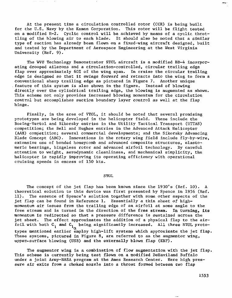
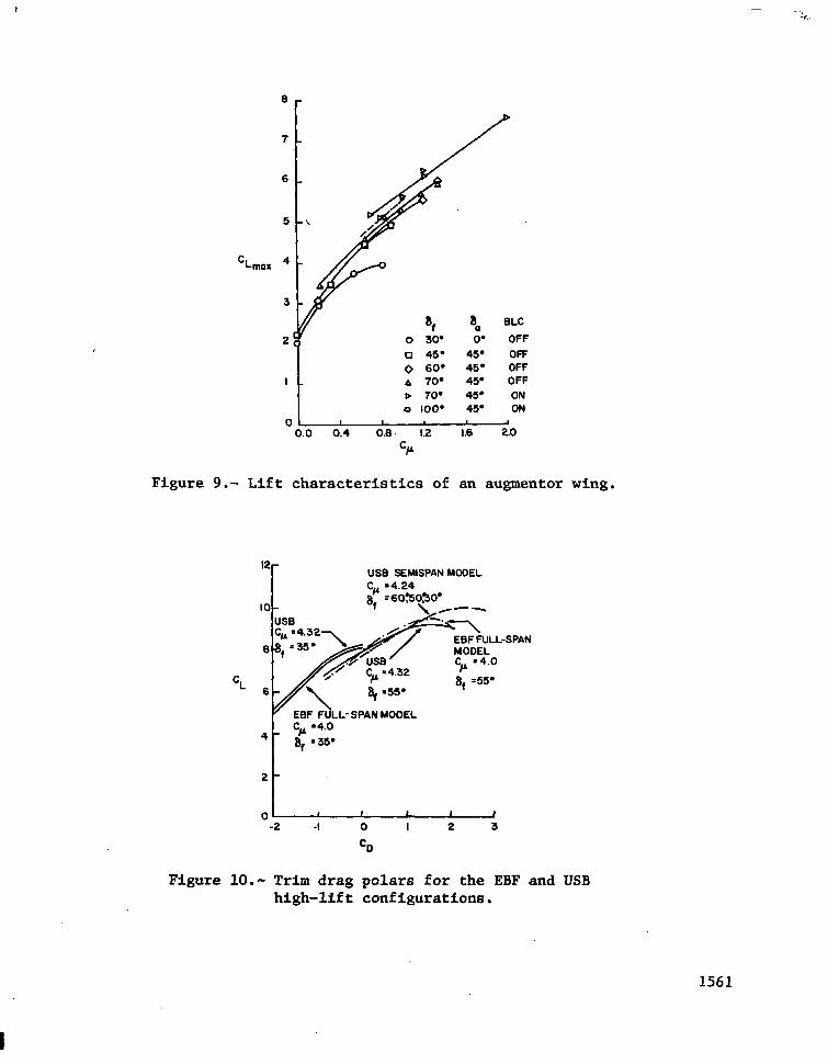
Aerodynamically, i t is d i f f i c u l t t o make a choice between the augmentor wing, USB and EBF systems. Figure 9 (from Ref. 12) p r e s e n t s C b a , as a f u n c t i o n of C,,
f o r t h e augmentor wing. Figure 10 (from Ref. 13) p r e s e n t s trim d r a g p o l a r s f o r b o t h t h e USB and EBF configurat ions. Obviously a l l three sys tems are capable of producing CL va lues much h i g h e r t h a n t h o s e a t t a i n a b l e w i t h o u t power. A l s o , f o r a given C,, v a l u e i t appears as i f t he pe r fo rmance of t h e t h r e e are about equal . The choice of one sys tem over the o ther w i l l probably depend upon such factors as mechanical complexity, weight, engine-out performance, noise, and cost .
The YC-14, which is y e t t o f l y , is descr ibed in References 14 and 15. Figure 11 d e p i c t s t h i s AMST which has a wing area of 163.7 m2 (1762 sq . f t . ) , a gross weight of approximately 751,745 N (169,000 lbs.) and powered by two GE CF 6-50D eng ines w i th an i n s t a l l ed t h rus t o f 214 ,848 N (48 ,300 lbs . ) . This air- p lane i s d e s i g n e d t o o p e r a t e r o u t i n e l y i n and out of 600 m (2000 f t . ) f i e l d s wi th a 120,100 N (27,000 lbs.) payload. Its approach speed is approximately 43.8 m / s (85 k t s ) whi le the t akeoff speed is 50.0 m / s ( 9 7 k t s ) . On l and ing t he trim l i f t c o e f f i c i e n t is approximately 3 .60 for a C,, of 0.78. The a i r p l a n e h a s several unique fea tures wor thy of no te . The USB f l aps ope ra t e i ndependen t ly t o p rov ide t h rus t vec to r con t ro l . The l i f t system is f u r t h e r enhanced by l ead ing edge blowing of the Krueger f laps through a series of c losely-spaced holes . Being landing l imi ted , the l ead ing edge BLC allowed a r e d u c t i o n i n wing area f o r t h e STOL miss ion . Accord ing to the spec i f ica t ions bo th AMST's, wi th one engine inope ra t ive must have a 0 . 3 g maneuver margin a t constant speed and a 20% speed margin from s t a l l i n o n e g f l i g h t . I n o r d e r t o o b t a i n good performance from the engine nozzles which blow the f laps , a door is inc luded on the ou tboard s ide o f each nozz le . For - takeoff the door is opened f o r maximum t h r u s t b u t c l o s e d i n t h e c r u i s e mode. It is a l s o i n t e r e s t i n g t o n o t e t h a t t u r n i n g i s enhanced i n t h e engine exhaust by the use o f vor tex genera tors which ex tend in to the f low when t h e f l a p s are lowered but retract i n t h e c r u i s e c o n f i g u r a t i o n .
Both t h e YC-14 and YC-15 employ advanced technology a i r f o i l s and are thus a b l e t o c r u i s e a t M = 0 .7 o r h ighe r w i th r e l a t ive ly t h i ck , unswep t w ings . They are thus approximately 40% f a s t e r t h a n c u r r e n t t ac t i ca l t r a n s p o r t s .
The YC-15, p i c t u r e d i n F i g u r e 1 2 , is c u r r e n t l y b e i n g f l i g h t t e s t e d and accord ing to Reference 16 i s performing up t o e x p e c t a t i o n s . I n a d d i t i o n t o t h i s r e f e r e n c e , a d e s c r i p t i o n o f t h e a i r c r a f t c a n b e f o u n d i n R e f e r e n c e 1 7 .
1554

For the STOL m i s s i o n t h i s a i r c r a f t h a s a weight of 676,100 N (152,000 lbs . ) comprised of an empty weight of 458,160 N (103,000 lbs . ) , a payload of 120,100 N (27,000 l b s . ) w i t h t h e r e m a i n d e r b e i n g t h e f u e l r e q u i r e d f o r t h e m i s s i o n . The a i r c r a f t is powered by four Prat t and Whitney JT8D-17 eng ines r a t ed a t 71,170 N (16,000 lbs. ) per engine. Its wing area is 162 m2 (1740 sq. f t .) with an a s p e c t r a t i o o f 7.0. Direct l i f t c o n t r o l i s provided through the use of s p o i l e r s . C o n t r o l i s accomplished through a fly-by-wire system which has s t a b i l i t y and control augmentation.
CONCLUDING REMARKS
As t h e r e s u l t o f wind tunnel and labora tory inves t iga t ions per formed i n r e c e n t y e a r s , improved thrust augmentors and blown flap systems have been developed . Because o f these e f for t s , several new V/STOL p r o t o t y p e a i r p l a n e s have been designed which hold promise of becoming operational.
REFERENCES
1. McCormick, B. W.: Aerodynamics of V/STOL F l i g h t . Academic P res s , New York, London, 1967.
2. Fancher, R. B . : Low-Area Ratio, Thfust-Augmenting Ejectors, J. of A i r - c r a f t , vol. 9 , no. 3, March 1972.
3. Quinn, B. : Compact Ejector Thrust Augmentation. J . o f A i rc ra f t , vo l . 10 , no. 8, August 1973.
4. Bevilaqua, P. M.: Evaluation of Hypermixing for Thrust Augmenting E j e c t o r s . J. of A i r c r a f t , v o l . 11, no. 6, June 1974.
5. Bevilaqua, P. M.: Analytical Description of Hypermixing and T e s t of an Improved Nozzle. J. o f A i rc ra f t , vo l . 13 , no. 1, January 1976.
6 . Robinson, C. A.: XFV-12 May Spur Navy VTOL Family. Aviation Week and Space Technology, April 16, 1973.
I
7. Anonymous: XFV-12A Proto type Components Tested. Aviat ion Week and Space , Technology, April 26 , 1976.
8. Williams, R. M.: App l i ca t ion of Circulat ion Control Rotor Technology to a Stopped Rotor Aircraf t Design. Firs t European Rotorcraf t and Powered L i f t A i r c r a f t Forum, U. of Southampton, England, September 1975.
9. Loth, J. L . , Fanucci, J. B . , and Roberts, S. C . : F l ight Performance of a C i rcu la t ion Con t ro l l ed STOL. AIAA Paper no. 74-994, 6 th A i rc ra f t Des ign , F l i g h t T e s t and Operations Meeting, Los Angeles, California, August 1974.
1555
I1 I I I I 1 ll11l11111111 II I

10. Schubauer, G. B.: Jet Propulsion with Special Reference to Thrust Au,gmentation. NACA TN 442, January 1933.
11. Spence, D. A.: The Lift of a Thin Jet-Flapped Wing. Proc. Roy. SOC., A238, 1956.
12. Koenig, D. G., Corsiglia, V. R. and Morelli, J. P.: Aerodynamic Characteristics of a Large-Scale Model with an Unswept Wing and Augmented Jet Flap. NASA TN' D-4610, March 1968.
13. Phelps, A. E. and Smith, C. C.: Wind-Tunnel Investigation of an Upper Surface Blown Jet-Flap Powered-Lift Configuration. NASA TN D-7399, December 1973.
14. Wimpress, John K.: Upper Surface Blowing Technology as Applied to the YC-14 Airplane. S A E Paper 730916, National Aerospace Engineering and Manufacturing Meeting, Los Angeles, California; October 1973.
15. May, F. W. and Bean, G. E.: Aerodynamic Design of the Boeing YC-14 Advanced Medium STOL Transport (AMST). AIAA Paper no. 75-1015, AIM 1975 Aircraft Systems and Technology Meeting, Los Angeles, California, August 1975.
16. Lewis, K. W.: YC-15 Flight Test Program Report. Proc. of 19th Symposium, SOC. of Experimental Test Pilots, Tech. Review, vol. 12, no. 4, Beverly Hills, California, September 1975.
1556

Figure 1.- Thrust-augmenting nozzle-diffuser combination.
A1 JGMENTATION
RATIO 9
2.0
C I . ,
1.c
- 0 -REFERENCE 5
0.12
0.20
I .o 2.0 3.0 DIFFUSER AREA RATIO f i
Figure 2.- Theoretical performance of a thrust augmentor including some experimental results.
1557

Figure 3 . - XFV-12A augmentor wing-flap system.
c
Figure 4.- Bell XV-15 t i l t -rotor VTOL airplane.
1558

I
c,
Figure 6 . - Lift
Figure 5.- Proposed X-wing VTOL configuration.
/ 5 0 %
/// -\
/ JET FLAP
I I I I I .04 .08 .I2 .I6 .20
C P performance of e l l ip t i c a i r fo i l s ec t ions with circulation control.
1559
I

I
EJECTOR
HIGH PRESSURE DUCT
Figure 7.- Flap system for West Virginia University's technology demonstrator aircraft.
Figure 8.- High-lift systems for current STOL developments.
1560
I
0 45- 45- OFF 0 60. 45- OFF A 70- 45- OFF b TO. 45. ON n 100- 45- ON
0 1 I I I
0.0 0.4 0.8- 1.2 1.6 2.0
cP
Figure 9.- Lift characteristics of an augmentor wing.
USB SEMISPAN MODEL C,, -4.24 8, -- 603030. \""
cL
I I t I I -2 -I 0 I 2 3
Figure 10.- Trim drag palars for the EBF and USB high-lift configurations.
1561

. .. .... . -~
Figure 11.- Boeing AMST YC-14.
Figure 12.- McDonnell Douglas YC-15 advanced medium STOL transport.
1562