one stage light oil burners - equipo de...
TRANSCRIPT

The Riello 40 F series of one stage light oil burners, is a complete range of productsdeveloped to respond to any request for light industrial applications. The Riello 40 F seriesis available in three different models, whit an output ranging from 30 to 202 kW, dividedin three different structures.All the models use the same components designed by Riello for the Riello 40 F series. Thehigh quality level guarantees safe working.In developing these burners, special attention was paid to reducing noise, to the ease ofinstallation and adjustment, to obtaining the smallest size possible to fit into any sort ofboiler available on the market.All the models are approved by the EN 267 European Standard and conform to EuropeanDirectives for EMC, Low Voltage, Machinery and Boiler Efficiency.All the Riello 40 F burners are fired before leaving the factory.
TS0031UK00
ONE STAGE LIGHT OIL BURNERS RIELLO 40 F SERIES F5 30 ÷ 60 kW
F10 54 ÷ 107 kWF20 95 ÷ 202 kW
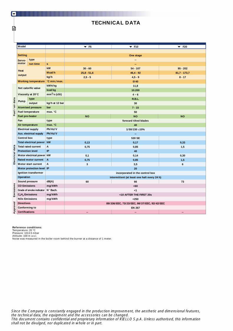
TECHNICAL DATA
Appro
val
Fuel
/ ai
r d
ata
Ele
ctri
cal d
ata
Em
issi
on
s
Heat
output
Net calorific value
Pump
Servo-motor
F5 F10 F20
One stage
--
--
30 - 60 54 - 107 95 - 202
25,8 - 51,6 46,4 - 92 81,7 - 173,7
2,5 - 5 4,5 - 9 8 - 17
0/40
11,8
10.200
4 ÷ 6
R.B.L.
30
7 - 15
50
NO NO NO
forward tilted blades
40
1/50/230 ±10%
--
530 SE
0,13 0,17 0,33
0,75 0,85 1,5
40
0,1 0,14 0,30
0,75 0,85 1,5
3 3,5 6
20
incorporated in the control box
intermittent (at least one halt every 24 h)
60 66 73
<60
<1
<10 AFTER THE FIRST 20s
<250
89/336/EEC, 73/23/EEC, 98/37/EEC, 92/42/EEC
EN 267
-- -- --
Model
Setting
type
run time
Working temperature
Viscosity at 20°C
type
output
Atomised pressure
Fuel temperature
Fuel pre-heater
Fan
Air temperature
Electrical supply
Aux. electrical supply
Control box
Total electrical power
Total rated current
Protection level
Motor electrical power
Rated motor current
Motor start current
Motor protection level
Ignition transformer
Operation
Sound pressure
CO Emissions
Grade of smoke indicator
CxHy Emissions
NOx Emissions
Directives
Conforming to
Certifications
s
kW
Mcal/h
kg/h
°C min./max.
kWh/kg
kcal/kg
mm2/s (cSt)
kg/h at 12 bar
bar
max. °C
type
max. °C
Ph/Hz/V
Ph/Hz/V
type
kW
A
IP
kW
A
A
IP
dB(A)
mg/kWh
N° Bach.
mg/kWh
mg/kWh
Reference conditions:Temperature: 20 °CPressure: 1013.5 mbarAltitude: 100 m a.s.l.Noise was measured in the boiler room behind the burner at a distance of 1 meter.
Since the Company is constantly engaged in the production improvement, the aesthetic and dimensional features,the technical data, the equipment and the accessories can be changed.This document contains confidential and proprietary information of RIELLO S.p.A. Unless authorised, this informationshall not be divulged, nor duplicated in whole or in part.

FIRING RATES
0
0,2
kW
3
0,4
0,6
0,8
1
1,2
1,4
4 5 6 7
40
8 9 10 15
50 60 70 80 90 100 110 120
Useful working field for choosing the burner
Test conditions conforming to EN 267 standards:Temperature: 20°CPressure: 1013.5 mbarAltitude: 100 m a.s.l.
10
2
4
6
8
12
14
0
2
30
11 12 13 14
130 140 150 160 170
16 17
180 190 200
1,6
1,8
2
16
18
20
F10F5
F20
hP
a (m
bar
)
mm
H2O
kg/h

HYDRAULIC CIRCUITS
FUEL SUPPLY
All the burners have a R.B.L. gearedpump with safety valve on the returncircuit.
F5 - F10 - F20
S
VR(NO)
1
2
U
Pump with filter andpressure regulator on thedelivery pipe
Oil return valve on thedelivery pipe
Oil input pipe to the nozzle
Oil return pipe from theregulator
Nozzle
Fuel pump
Fuel feed to the burner can be from the right or the left sideon all models.
S
1
VR(NO)
2
U

6
Type of system that can be installed
Difference in height
Internal pipe diameter
Difference in height ≤ 4 m
Burner
Pump
Filter
Shut-off solenoid valve
Suction pipework
Bottom valve
Return pipework
H
Ø
P
1
2
3
4
5
6
7
DIMENSIONING OF THE FUEL SUPPLY LINES
The fuel feed must be completed with the safety devices required by the local regulations in force.
The table shows the choice of piping diameter for the various burners, depending on the differencein the height between the burner and the tank and the distance between them.
Pipe size
H (m)
0
0,5
1,0
1,5
2,0
3,0
3,5
Ø8mm
L max (m)
35
30
25
20
15
8
6
Ø10mm
L max (m)
100
100
100
90
70
30
20
Ø8mm
L max (m)
-
10
20
40
60
-
-
Ø10mm
L max (m)
-
20
40
80
100
-
-
Type A system
MAXIMUM EQUIVALENT LENGTH OF THE PIPEWORK L[m]
Type B system
HP
H
1
4
10 cm2
3
1
2
7 5 H
P
H
1
4
10 cm2
5
3
7
A
6
3
3
B
H
P
1
2
43

COMBUSTION HEAD
VENTILATION
The ventilation circuits always ensurelow noise leve ls wi th h ighperformance of pressure and airdelivery, inspite of their compact size.
All the models have adjustablecombustion heads.
Simple adjustment to the combustionhead allows adapting internalgeometry of the head to the maximumrated output of the burner.
Combustion head
Air suction
With simple adjustments, the burner canbe adapted to combustion chambers thatare slightly different from those used inthe tests.
1,6
10,80,60,50,40,3
0,2
0,1
Ø cmd=30 d=50d=40d=25
50403020 50040030020010010
454035302520151051
kW
kg/h
L(m)
2 3 4 6 7 8 9
Example:burnt thermal delivery = 3 kg/h;L (m) = 0,25 x 3 = 0,43 (m);Ø = 30 (cm)
Combustion chamber dimensions used in the test laboratory
L (m) = 0,25 x kg/h
Ø
L

ADJUSTMENT
All these models are one stage operation.
Air damper
BURNER OPERATION MODE
(A) Lock-out is shown by a led on the appliance.
Correct operation
0s The burner begins the ignition cycle.0s-12s Pre-purge with the air damper open.12s Ignition.
Lock-out due to ignition failure
If the flame does not light within the safety limit (~ 5s) the burnerlocks-out.
IGNITION
Ou
tpu
tC
hec
ked
Var
iab
le
bar°C
ON
OFF
time
time
ON
OFF
One stage operation
~12 s ~5 s~12 s
TR
V
Ignitiontransformer
Lock-out lamp
Normal Lock-out due to ignition failure (A)
time (s) time (s)
M

ELECTRICAL CONNECTIONSto be made by the installer
Electrical connections must bemade by qualified and skilledpersonnel in conformity with thelocal regulations in force.
Control box fitted with an ignitiontransformer
“ONE STAGE” OPERATION
F5 - F10 - F20
The following table shows the supply lead sections and types of fuse to be used.
F5Model
A
mm2
FL
230V
61
F10
230V
61
F20
230V
T61
F = Fuse L = Lead section
TR - Regulating thermostatTS - Safety thermostat (with manual resetting)SB - Remote lock-out lamp (230V 0,5A max)F - Fuse
L N
TR
NL
~50Hz 230V
F
PE
TS
56789 4 3 2 1 Terminal block of control-box
SB

EMISSIONS
The emission data havebeen measured in thevar ious models atmaximum output, inconformity with EN 267standard.
NO2 EMISSIONS
mg
/kW
h
174176
178
180
182
192
CO EMISSIONS
mg
/kW
h
0
5
10
15
20
25
SOUND EMISSIONS (sound pressure)
dB
(A)
0
20
40
60
80
100
F5
184186
188
190
F10 F20
F5 F10 F20
F5 F10 F20

OVERALL DIMENSIONS (mm)
These models are distinguished by their reduced size, inrelation to their outputs, which means they can be fitted toany boiler on the market.
X
Z
Y
BURNERS
PACKAGING
BURNER-BOILER MOUNTING FLANGE
N
11
M
H
L
I
Z
315330367
B= =
A
C D
E
F
G
A
233262298
B
272305350
C
76108118
D
240265299
I
180189213
728399
H L
758399
M
130140160
N
150170190
Model
F5
F10
F20
89105125
G
414445
FE
180204230
F5
F10
F20
Model
Model
F5
F10
F20
X Y kg
373413473
305338383
111215
F20F5 - F10
N 11
M
H
L
I
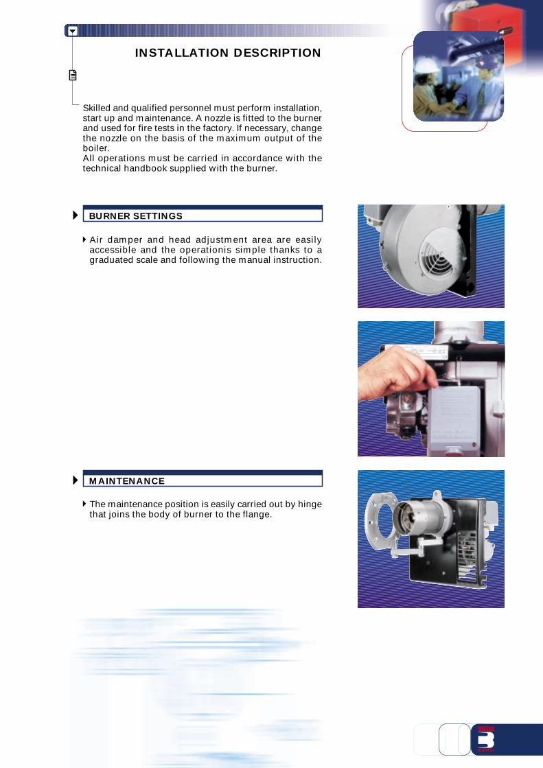
INSTALLATION DESCRIPTION
Skilled and qualified personnel must perform installation,start up and maintenance. A nozzle is fitted to the burnerand used for fire tests in the factory. If necessary, changethe nozzle on the basis of the maximum output of theboiler.All operations must be carried in accordance with thetechnical handbook supplied with the burner.
The maintenance position is easily carried out by hingethat joins the body of burner to the flange.
MAINTENANCE
Air damper and head adjustment area are easilyaccessible and the operationis simple thanks to agraduated scale and following the manual instruction.
BURNER SETTINGS

BURNER ACCESSORIES
Extended head kit
Kits of extended heads are available.
Kit codeBurner
Kit for extended combustion head
Long headversion
length (mm)
Standardhead
length (mm)
Spacer kit
Using the special accessories, the burner can be pulled back to reduce head penetration into thecombustion chamber.
3006001
3000688
3000638
3000686
3000687
3000726
3000728
3000643
3000770
3000644
3000771
F5
F5
F5
F5
F5
F5
F5
F10
F10
F20
F20
76
76
76
76
76
STANDARD
CONIC
108
108
118
118
90
90 INOX
107
121
121 INOX
CONIC HEAD
107 CILINDRIC HEAD
168
250
178
260
Light oil filter
Kit code
3007642
3000672
3000673
F5
F10
F20
Burner
Head length reduction kit
Pulling back (mm)
25
25
25
Accessory
Spacer
Spacer
Spacer
Biodiesel kit
Kit code
3000978F5 - F10 - F20
Burner
Kit to use biodiesel
Kit code
3000926F5 - F10 - F20
Burner
Light oil filter
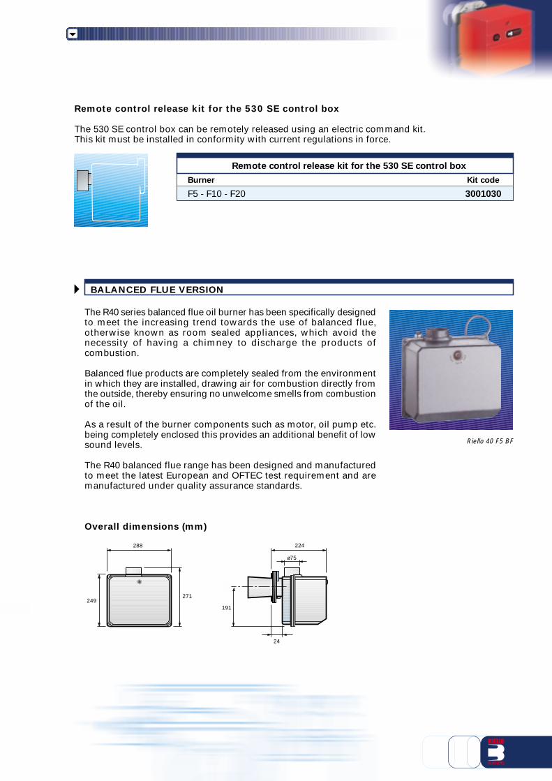
BALANCED FLUE VERSION
Riello 40 F5 BF
Remote control release kit for the 530 SE control box
The 530 SE control box can be remotely released using an electric command kit.This kit must be installed in conformity with current regulations in force.
Kit code
3001030
Burner
Remote control release kit for the 530 SE control box
F5 - F10 - F20
The R40 series balanced flue oil burner has been specifically designedto meet the increasing trend towards the use of balanced flue,otherwise known as room sealed appliances, which avoid thenecessity of having a chimney to discharge the products ofcombustion.
Balanced flue products are completely sealed from the environmentin which they are installed, drawing air for combustion directly fromthe outside, thereby ensuring no unwelcome smells from combustionof the oil.
As a result of the burner components such as motor, oil pump etc.being completely enclosed this provides an additional benefit of lowsound levels.
The R40 balanced flue range has been designed and manufacturedto meet the latest European and OFTEC test requirement and aremanufactured under quality assurance standards.
Overall dimensions (mm)
288
249271
224
24
ø75
191
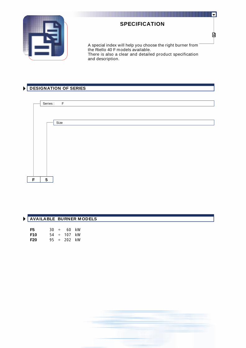
SPECIFICATION
A special index will help you choose the right burner fromthe Riello 40 F models available.There is also a clear and detailed product specificationand description.
AVAILABLE BURNER MODELS
F5 30 ÷ 60 kWF10 54 ÷ 107 kWF20 95 ÷ 202 kW
DESIGNATION OF SERIES
F 5
Size
Series : F
Burner:
Completely automatic monobloc light oil burners, with one stage operation fitted with:- Fan with forward inclined blades- Metallic cover- Fixed air damper with adjustment- Single phase electric motor 230 V, 50 Hz- Combustion head fitted with:
- stainless steel head cone, resistant to high temperatures- ignition electrodes- flame stability disk
- Geared pump for fuel supply, fitted with:- filter- pressure regulator- attachments for fitting a pressure gauge and vacuum meter
- internal by-pass for preparing for single-pipe installations- Fuel feed solenoid valve incorporated in the pump- Photocell for flame detection- Electronic flame control equipment- Light oil nozzle- IP 40 protection level.
Approval:- EN 267 standard.
Conforming to:- Directive 89/336/EEC (electromagnetic compatibility)- Directive 73/23/EEC (low voltage)- Directive 98/37/EEC (machinery)- Directive 92/42/EEC (efficiency).
Standard equipment:- Two flexible pipes for connection to the light oil supply line- Two nipples for connection to the pump- Flange, screws and nuts for fixing- Thermal screen- Instruction handbook for installation, use and maintenance- Spare parts catalogue.
Available accessories to be ordered separately:- Extended head kit- Spacer kit- Light oil filter- Biodiesel kit- Remote resetting kit- Balanced flue version.
SPECIFICATION DESCRIPTION

ISO 9001 Cert. n. 0061
RIELLO S.p.A. - Via degli Alpini, 1 - 37045 LEGNAGO (VR) ItalyTel. ++39.0442630111 - Fax ++39.044221980
Internet: http://www.rielloburners.com - E-mail: [email protected]
Line
agra
fica
Since the Company is constantly engaged in the production improvement, the aesthetic anddimensional features, the technical data, the equipment and the accessories can be changed.
This document contains confidential and proprietary information of RIELLO S.p.A.Unless authorised, this information shall not be divulged, nor duplicated in whole or in part.