oominittee - massachusetts institute of technology
TRANSCRIPT

MASS PRODUCED BUILDING SYSTEM FOR UNSKILLED LABOR
By:
Angelo Petrozzelli, Boston Architectural Center,
Certificate of Architecture, 1966
A THESIS SUBMITTED IN PARTIAL FULFILLMENT
OF THE REQUIREMENT FOR THE
DEGREE OF MASTER OF ARCHITECTURE
AT THE MASSACHUSETTS INSTITUTE OF TECHNOLOGY
June 1972
Department of Architecture, May 12, 1972
esis Superv 6r
Chairmnan, Depar aent Oominittee OnGrad e Students
Rotch
JUN 27 1972

MITfibrariesDocument Services
Room 14-055177 Massachusetts AvenueCambridge, MA 02139Ph: 617.253.2800Email: [email protected]://libraries.mit.edu/docs
DISCLAIMER OF QUALITY
Due to the condition of the original material, there are unavoidableflaws in this reproduction. We have made every effort possible toprovide you with the best copy available. If you are dissatisfied withthis product and find it unusable, please contact Document Services assoon as possible.
Thank you.
The images contained in this document are ofthe best quality available.

405 Saratoga StreetEast Boston, Massachusetts 02128
May 12, 1972
Dean William PorterSchool of Architecture and. PlanningMassachusetts Institute of Technology77 Massachusetts AvenueCambridge, Massachusetts
Dear Dean Porter:
In partial fulfillment of the requirements for the degree ofMaster in Architecture, I hereby submit this thesis entitled."Mass Prod.uced. Build ing System For Unskilled. Labor".
Respectfully yours,
Angelo Petrozzelli
Enclosure

ABST RACT
A Strategy For Developing A Mass Produced Building System ForUnskilled Labor
by Angelo Petrozzelli
Submitted. to the Department of Architecture on May 12, 1972 inpartial fulfillment of the requirements for the Degree ofMaster of Architecture.
It should. be noted that this thesis is a continuation of an.earlier submission by the office of Imre and Anthony Halasz,Inc. and. various other participants. This submission was partof the H.U.D. Operation Breakthrough Program RFP No. H-55-69.
The reason for selecting the development of a mass producedbuild.ing system for unskilled. labor is my reaction to presentlyavailable housing systems that by their size and. complexitycreate a physical and human strait jacket Ill suited. to userparticipation in any stage of its development or existence.This thesis prepares the ground. work for a building systemsympathetic to this need and applicable in the immediatefuture at minimal cost.
It is the hope that this thesis will stimulate a research pro-gram to d.evelop a full-scale model to test and. improve thesystem.
The illustrations shown in the text deal with housing, butthe system is not limited to this use. It seems to adaptwell to other building types with similar clearance and spanrequirements.
Thesis Supervisor: John SteffianAssociate Professor of Architecture
iI

ACKNOWLEDGEMENTS
I wish to express my deepest gratitud.e to Professor John
Steff ian and Professor Waclaw Zalewski for their unselfish
participation during this study for my graduate work, and I
wish to include in my thanks the many faculty members and staff
of the Department of Architecture.
I wish to thank my associates within the staff of the archi-
tectural office of Imre and Anthony Halasz, Inc. especially
Imre and. Anthony Halasz for giving me the opportunity to com-
plete my work at the institute and for their contributions to
my academic enrichment. I also wish to thank them for the
personal relationship which has developed not only during this
experience, but also within the last five years since I have
known them.
My gratitude extends to Mr. Frank Ransome of the Wheeling Steel
Corporation, and Mr. Kenneth Sisson of American Architectural
Iron, for help in obtaining the structural members and universal
connection development.
Finally, my deepest gratitude to the members of my immediate
family, especially my parents, for understanding and unfailing
support over the number of years it has taken me to complete my
education. Without their support I do not know what I would have
done. I also wish to thank my personal friends who have
encouraged me to continue with my studies.
III

TABLE OF CONTENTS
TITLE PAGE
ABSTRACT 11
ACKNOWLEDGEMENTS 111
TABLE OF CONTENTS iv
PART 1: GOALS AND DESCRIPTION OF THE SYSTEM
a. General
b. Architectural
c. Structural
d. Interior Work
e. Mechanical, Electrical
f. Foundations
PART 2: SYSTEM ADAPTABILITY 10
a. Housing Types and Scope
b. Climatic Areas
c. Geology and. Soils
d. Site Topography
e. Site Size
f. Site Situations
g. Changes
h. Regional Application
PART 3: SYSTEMS COMPONENTS 15(Introduction of system as related. to housing)
iv
PART 4: MODULAR STUDIES (System Applications) 33
a. General Site Matrix
b. Diagrammatic Layout of Housing Matrix
PART 5: DIAGRAMMATIC EXAMPLES OF HOUSING TYPES 39
a. Row House using a 20'-0" Matrix
b. Row House using a 32'-0" Matrix
c. Townhouse
PART 6: PHOTOGRAPHS OF MODEL 75
PART 7: BIBLIOGRAPHY 80
PART 8: MECHANICAL SYSTEM DIAGRAMS 63
V

GOALS AND DESCRIPTION
OF THE SYSTEM~ -l1-

A. BUILDING SYSTEM CONCEPT
1. GOALS AND DESCRIPTION OF THE SYSTEM
a. General
The basic rationale underlying the concept of this
proposed building system-is that the system should
not only fulfill the needs for shelter but also
should. become a source of employment, primarily for
the unskilled of our society. The essential feature
of this system is simplicity, based on the following
objectives and solutions.
1. Participation by the unskilled or semi-skilled
members of society, who would be able to
erect, and maintain the system with minimal
training and. supervision.
ii. Minimal capital investment for production and
construction so as to allow immediate applica-
tion in any volume, anywhere and throughout
the country.
iii. The use of available commercial products in
order to minimize new building components. A
few of the system components may be especially
fabricated., but the parts will be standard.
It is hoped that these components will be
stocked in local outlets.
-2-

iv. Shop fabrications should be done with minimum
investment on the part of the supplier. Fab-
rication of some of the components may be
accomplished on the site at first in order to
keep investment to a minimum.
V. The components shall be of a size and weight
that can be handled. manually by two people.
This will result in modest spans and small
components. Small component size will allow
greater individual freedom for different
assemblies and will allow the system to be
adapted to a wide variety of needs.
vi. Simple mechanically fastened joints are
intended for the entire system without using
special equipment and skilled. labor.
vii. A universal joint is proposed. at all inter-
sections of structural members.
viii. The system will expand or contract in every
direction due to the use of the universal
joint. Change and. growth can occur without
disruption of the finished spaces already
occupied..
viiii. The system will take advantage of readily
available components from other systems that
are practical and usable.
-3-

x. High standards of quality, low cost, easy
adaptability to individual preferences, com-
bined with the consumer's possible involve-
ment in the production and marketing process,
should assure his acceptance and identifica-
tion with the housing product.
Following this logic the system consists of a
series of independent structural frames with
replaceable infill panels that constitute all
finished surfaces. Prefabricated mechanical units
will form an integral part of the system.
b. Architectural
The architectural character of the system.
i. Additivity
One of the chief dangers generated by pre-
fabricated and preassembled. industrial systems
is that they often eliminate flexibility.
This system, both in the relationships of its
components to each other and in the components
themselves, is based on the principle of
additive flexibility. The resulting environ-
ment, be it an individual house or a complex
settlement, can be molded. and. articulated
according to specific need.s and human desires
rather than forced. into an imposing precon-
ceived industrial strait jacket.
11. Component Parts
The principle of additivity is maintained by
the relatively small size of the basic floor
and wall panels between the structural frames.
Since the assembly of the components is
designed for the utmost simplicity, the
number of joints does not adversely in-
fluence cost. However, by virtue of modest
spans, small components, and. great individual
freedom of different assemblies the system
can adapt itself to a wide variety of needs.
Old. systems based on large component parts
often offended. our sense of human dignity
by limiting additive modulation. The selec-
tion of the smallest component parts, readily
available through the regular channels of
the construction industry has its advantages
not only in cost, easy handling, self-help,
etc., but chiefly in that the small compon-
ent parts enable the user to contribute to
the form of his environment, exercise choice
and initiative, and. thus restore his pride in
his place of living because he can adapt the
system to his specific needs and requirements.
-5-

ii1. Diversity
Since the system consists of relatively small
components and. a very large degree of addi-
tive flexibility, it can adapt itself to
different housing densities, site conditions,
and. individual needs. Since the wall panels
are designed for additive flexibility, they
can adapt to different climatic conditions,
as well as various zoning and building code
requirements.
The main test of every contemporary system
is its behaviors in terms of change and
growth. The proposal allows change and
growth on different levels.
It can most easily expand. in every direction
by virtue of the universal joint.
It permits the alteration of the standards
of housing units themselves, even in higher
d.ensities, by exchanging components without
interfering with the rest of the units.
Since the proposal d.oes not concern itself
with a building as a product, but with an
additive process it will change itself through
field experience, demand., research and human
ingenuity.
-6-
The ease of assembly implies the ease of
dismounting. Change and growth demands
addition as well as removal of parts in
relation to the whole, without disruption.
c. Structural
1. Low-rise Construction
The basic structure consists of a light
gauge metal frames and infill panels that
form all finished surfaces.
A prefabricated "universal" joint piece,
which is placed at every intersection be-
tween frame members, allows simple attach-
ment of column and. beam units. No element
exceeds 150 pound.s in weight. All frame
connections in the field are by high tensile
bolts. Details are such that while all the
frame parts will be prefabricated in a shop,
all assembly will be handled. by unskilled
labor, without any hoisting equipment.
All panels, for floors, exterior and interior
walls and. partitions, are of standard manufac-
ture and are set into the frames by simple
connections. The use of advanced. fastening
devices is contemplated to assure easy, rapid
and safe assembly. Fairly large tolerances
O-7-

are employed to avoid the need for exacting
precision.
The frame structure is designed to withstand
all vertical loading and the effects of wind.
or earthquake forces.
ii. High-rise Construction
The system is adaptable to any building
height with the provision that it becomes a
subsystem in a megastructure whenever it ex-
ceeds four stories. In such a case a basic
concrete frame, consisting of columns, core
walls and. floor slabs at four-story intervals
will be constructed. The structure serves as
a four-hour fire barrier, both in vertical
and. horizontal planes, in addition to its
load bearing function. The low-rise light
gauge steel frames and infill panels will
be plugged into the megastructure, with pro-
visions for fire protection.
While the megastructure will demand skilled.
labor, all the infill structure will be
manufactured and. assembled exactly as the
low-rise units.
d. Interior Work
Prefabricated assemblies of stairs, cabinets,
-8-

partitions and closets are introduced into the
system, at a wide variety of possible modular
applications, allowing any pattern of growth and.
change,
e. Mechanical, Electrical
The general approach, here as well as in the struc-
ture, is based on the following premises:
i. Simple mechanical installation by unskilled
labor.
ii. Individual control of the mechanical system
in each dwelling and independence from
occupants of other units.
iii. Possibility to change, remove or upgrade the
mechanical installations.
A suggested outline specification has been developed
for some housing units investigated. These are
included in the Appendix.
f. Foundations
The system is designed to be supported at discrete
points, the cases of the frames. As such, it is
applicable to practically any soil condition. The
flexibility of the steel frames and the tolerances
between infill panels make the system relatively
insensitive to minor differential settlements of
the supports.
-9-

SYSTEM ADAPTABILITY-10-

2. SYSTEM ADAPTABILITY
a. Housing Types and Scope
The proposed system will allow maximum freedom of
choice and degree of self-participation at densities
up to 15 units per acre. At these densities the
capacity for growth and change can be employed to
a very large extent. Simple family detached or
attached homes can expand in all directions in
small or large increments by the use of building
components (stair, mechanical unit) and by use of
columns, universal joints and panels.
The limit of the proposal serving as a primary
system is in the range of 40 dwelling units/acre.
The accompanying illustration assumes the following
restraints:
100% parking
on-grade parking
limited walking distance from car to units
walk-up with maximum two flights of stairs
emergency and service traffic only within
the residential matrix
no more than four stories (possible duplex
on top)
Residential densities higher than 40 u/a will
adapt the proposed components as infill or
-11-
secondary systems. These densities will change
the rationale of parking relationships and circu-
lation considerations in general.
The attached. site application addresses itself
to the upper limits of the system in terms of
its residential densities as demonstrated in the
general site matrix. This type of site utiliza-
tion is a long neglected. prototype for urban
housing.
The well known later d.ay prototypes in the lower
and upper extremes of urban residential densities
did. not fulfill the aspirations and promises of
their urbanistic conception. Not only did they
stereotype their architectural presence but a non-
compromising social segregation followed.. The
careful study and revitalization of middle density
housing is most timely and necessary. The proposed
system is best suited. to such middle density appli-
cations while still effective in all other types
of residential development.
b. Climatic Areas
No restriction.
Steel frame is designed to resist any specified hori-
zontal and vertical load. Infill construction is
such that any insulation value is attained by using
an appropriate insulating blanket.
-12-

c. Geology and. Soils
The system is usable on soils with poor natural
drainage and unstable soils, d.ue to the relative
flexibility of the structure which is capable of
adjusting to differential settlements without
excessive stress. All infill panels allow minor
distortion without damage to them.
d. Site Topography
At sloping sites footings with piers of adjustable
length will allow the use of the system both in
the same form as on flat sites as well as with
the introduction of partial lower levels.
e. Site Size
The system is adaptable to any site size.
f. Site Situations
The basic concept of the system, its simplicity
in the use of unskilled. labor and finished light
materials that are available anywhere, renders it
applicable to any site situation and. basically
independent of local labor and material supplies.
The presence of existing or removable structures
d.oes not restrict the applicability of the system,
g. Changes
All components are removable or can be added on,
as desired.. Thus the standard. of surface finishes,

cabinets, etc. can be improved at any time by
simple exchange of panels. Expansion and re-
arrangement are handled. similarly. In many cases
the frame may be erected. at the time of construc-
tion, to serve as porch or terrace, and. later en-
closed by snapping the finished panels into the
frames.
h. Regional Applications
No restriction.
-14-

SYSTEM COMPONENTS-15-

PREFABRICATEDFLOOR PANEL
-'7
7'
7 -
CANTILEVER NWITH CONNECTORATTACHED
BEAMS
6-COLUMN
TYPE: B
K
ISOMETRIC OFTYPICALCOMPONENTS
0 2 4 8

ELEVATION OF UNIVERSAL CONNECTOR: TYPE A
I2GA.JOISTHANGER
COLUMN
SLEEVE
0 1 2
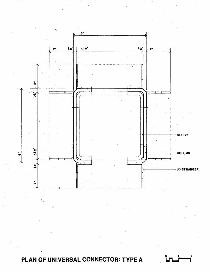
-SLEEVE
COLUMN
JOIST HANGER
C-'
PLAN OF UNIVERSAL CONNECTOR: TYPE A0 1 2
I
;D
I.
I.
T
474k'II.
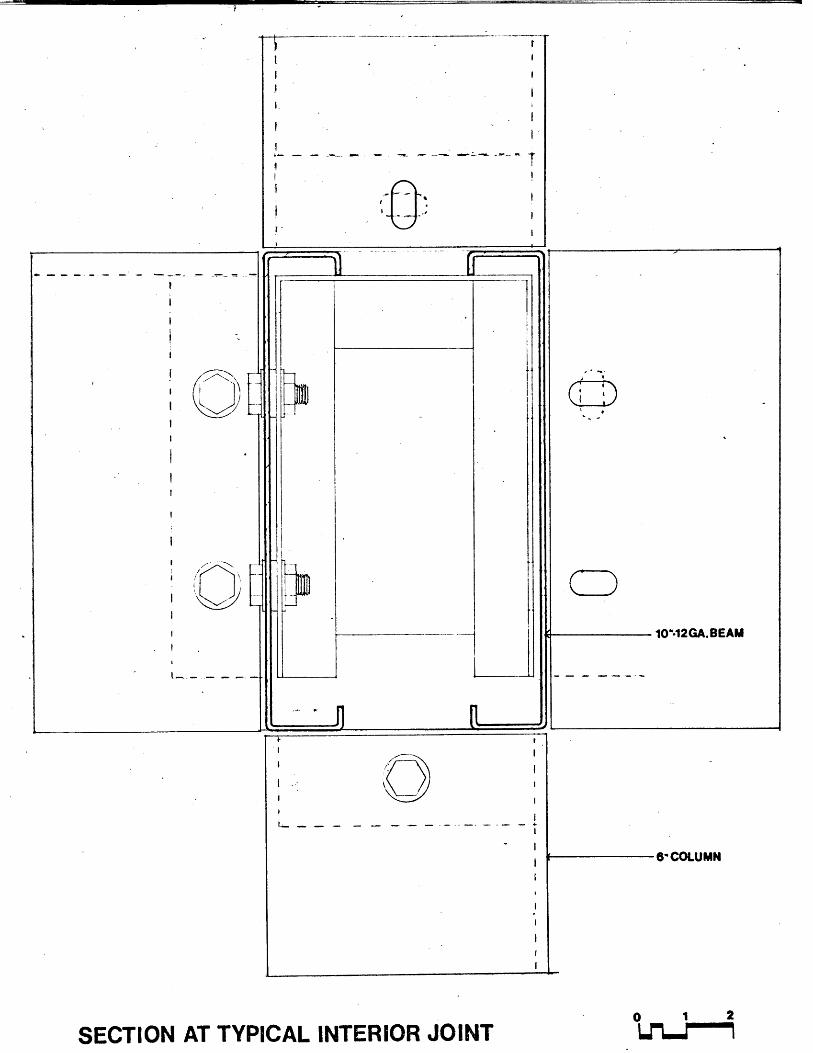
SECTION AT TYPICAL INTERIOR JOINT
6-COLUMN
0 1 2id"LJ."""""
10"-12GA.BEAM
I

l0'-2GA.BEAM
PLAN OF TYPICAL INTERIOR JOINT0 1 2W"6.rmm7

-- ----.- .- .-- -. - -I
I-,£~ )
I fI.
I II. I~
'---II I.
~ --
- -I
S.111e10
3A8'PLYWOOD
BUILDINGPAPERPREFABRICATED
t-R PANEL
u~ - - -I-
- V
cc172
~c7
~IZ§.
cEZT'
I
%~ -I - -
-i
6"u CLOSURE
SECTION AT TYPICAL INTERIOR JOINT
(C1
I
f
-1-. - -
0 1 2121-/"""""

-~ .-... 9- 9.9
IZIZIL- L
- ~~~1
-I
1~
- --- 4.
VI I
PREFABRICATED- FLOOR PANEL
Z-------- -7 - I
.L1Th
-1 I M i Fri I I-
---- 4------ -I - 1L
2 W~rF1
- --
...............
ii,
,~jII1 \)K
I'
II IIiii I
I I. I-
I I
- I
,, x x 'JIlL
~~1~
-Uii
--- 4IXDBVWflflfl- - ~ -
- -
-
0 1 2LJ"LJ""""""
-I-IA
- I. I-III
ii iiI I- -- III
:K I
- I
PLAN OF TYPICAL INTERIOR JOINT
lIFI
I

I
C
C
r
EXTERIOR WALL SECTION
PLATE
INSULATEDPANEL
|TRANSLUCENTWALL
0 1 2
Ll"l """"""
a
I

~~~1~
t -
4 - ~~~~1
- -
r
-I
-
A--x
- - - - - - - - - ~~1
-I
I.
_______ '4. '4, i
~' ;\~ \ 1\\'
I/I ~'
II I~ ~ ~
"' 7
-~-1
- I
-I
I -
~iL
PLAN OF EXTERIOR CORNER0 1 2Lfl-/""""
~zjI
t *i I1: 1
~~~~1
-. 1
/
--- ~----I7
COVER PLATEAT CONNECTOR
TRANSLUCENTWALL
3I OR 4
_-z 1 -7--- 7
*1* -
* 7
A
/
- -t
K N
1
-I
I.
-II..
~1:
A-
-I.
I I
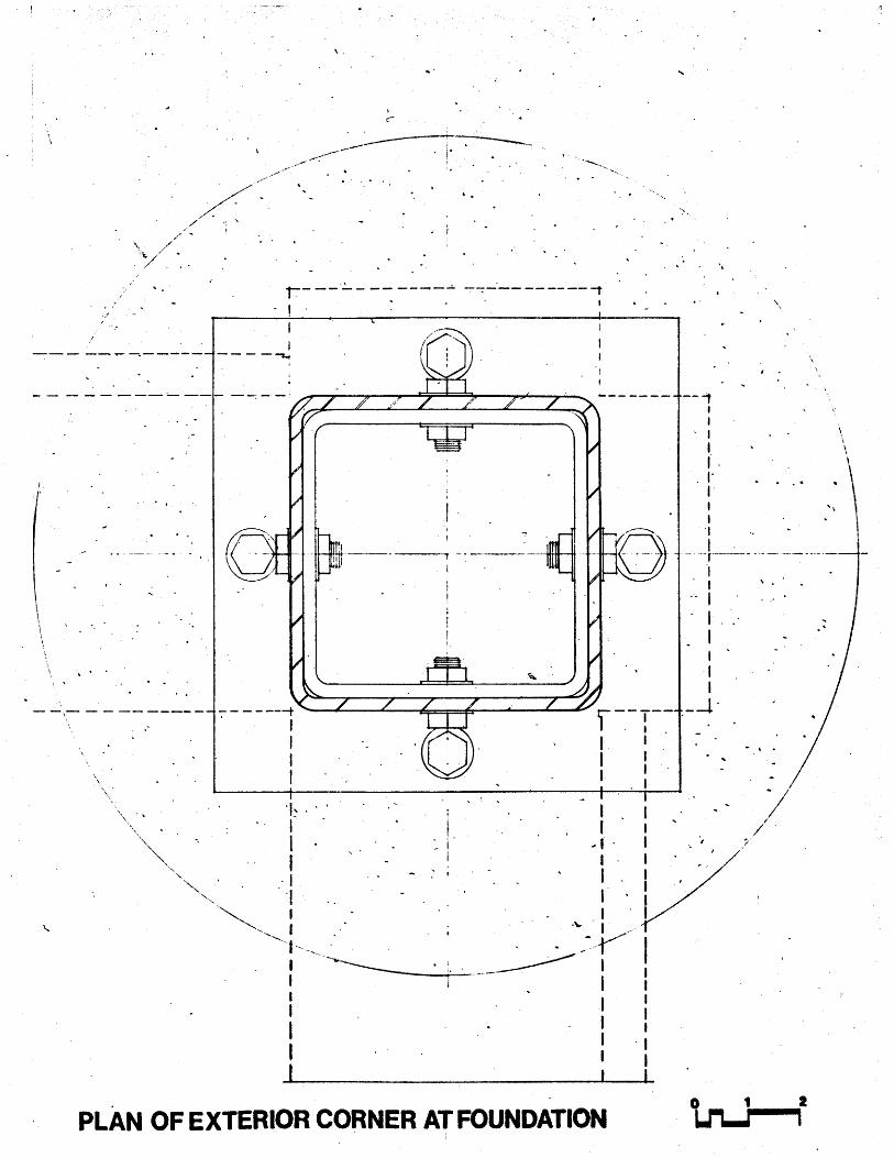
PLAN OF EXTERIOR CORNER AT FOUNDATION0 1 2
se - e- -.- Z-- - s- - - -
-I
k
.1
7: A I 717 ~~t~iI'7 "NK.
.1N
\\ \\** -* * . .
- - --I-
I ~di
-i *1.
- 1-
~4j
''It I .''
I.. - -
i (i-
) -
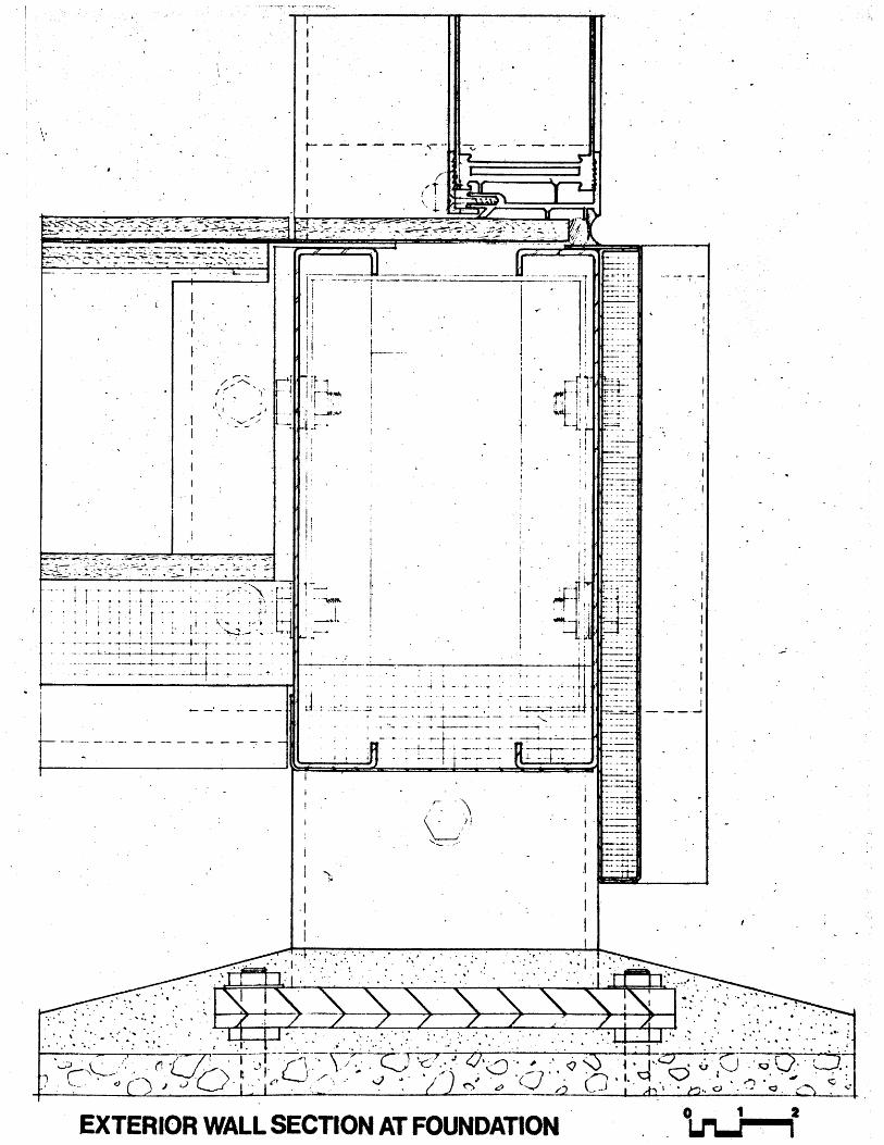
EXTERIOR WALL SECTION AT FOUNDATION
iA~

EXTERIOR WALL SECTION AT ROOF ~Lr~9

"2"
- *
10%2GA BEAM
PLANS OF UNIVERSAL CANTILEVER CONNECTOR JOINT TYPE: B

V,
r
* 1.-i4.-JIIA.~1
4 W4J W 4
141F 4
- IT
OPEN
a
8
0;
I.
I.
I I
-I I
h"j ? /4"A
I.o I I
iv _____N'___
SLEEVE
ELEVATIONS OF UNIVERSAL CANTILEVER CONNECTOR: TYPE B0 1 2LM'.2""""""
kl Je"
I '---'
It I II I IIII I
* iiii4
I I
I I
I I
I I1~'Is i~II II
I I
11I I
II I
It
r-
I I
I II II I
I I
I II I
I II I
I. I
I I
E-.JOIST HANGER
- 2x6COLUMN

L 2SIDE ELEVATION-TYPE B CONNECTOR END ELEVATION 0 1 2

EXANSION
MINIMUM UNIT 2 1 BEDROOM UNIT
SELECTIVESEXPANSION
VERTICAL3 3 BEDROOM UNIT 4
3 BEDROOM UNITADAPTED TO SLOPING SITE
STRUCTURAL ADAPTABILITY
1

/ %
/
'I4C
N
/
//
II/
/
N
)
/N
110
FLOOR PLANS %A

SYSTEM APPLICATION-.33-

0O
Proposed system primary
Max. possibility for self-help
Adaptability and change And
growth for each Living Unit
Proposed System Primary
Establishes a Range of
possibilities for self-help,Adaptability and change and
growth for each Living Unit
Proposed System subsystem of
'Structural Matrix. Limited
possibility for self-help-Adaptability and change and
growth,for each living unit
1-2 stories .detached
1-3 stories attached
3-4 stories attached
High Density4;r0
Construction Cost ($/L.U.)
Environmental Cost (S/L.U.)
- -.-.--I -o -
CD
Ca
1~
I.L
C
VWV
/
III
:Z
ct\
SYSTEM APPLICATION DIAGRAM
r__

SYSTEM APPLICATION DIAGRAM
This diagram is a generalized illustration of the relationship
between cost and type of housing development. Housing is
divided into three categories in terms of number of living units
per acre. These categories and. the implications of the pro-
posed structural system for each category have already been
discussed.
The solid-line curve in the diagram represents the relation-
ship between construction cost and density of housing. The
dashed-line curve represents the relationship between environ-
mental cost and intensity of land use, i.e., the environmental
factors, or costs, necessary to develop a socially and economi-
cally successful community. The underlying assumption is that
the success of a housing development depends not only on the
comforts provided by the living unit itself, but also on the
services available to the community. These services range from
utilities, open spaces, parks and recreation areas, schools,
shopping centers, community centers, transportation networks,
etc. to more abstract benefits which determine the quality of
socio-economic life. Based on past experience with housing
types and community development, it is assumed that the cost
per living unit of these supporting services decreases as the
intensity of land use, hence the sharing of facilities by larger
numbers of living units, increases.
-35-

However, this relationship is not directly proportional. The
diagram indicates that the benefits of increasing land use
intensity grow in smaller increments as increasingly high
densities are reached.
These considerations led to the selection of the 15-40 living
units per acre density as the area of intensive study; (the
shaded area in diagram). This type of housing was selected
because it represents the low to medium range in terms of
construction cost and promises better environmental benefits
with increasing land. use intensity.
The 15-40 living units per acre d.ensity was selected for
intensive study because it appears to be more economical
in terms of construction cost and of environmental cost, and
also offers a desirable range of possibilities for self-help,
adaptability, and change and. growth for each living unit.
The proposed construction system may be used to develop a
wide range of site plans at a density of 15-40 living units
per acre. The "General Site Matrix" and the "Diagrammatic
Layout of Housing Matrix" illustrates a possible application
of this system.
-36-

LiLLLIfltI LLLLLL ~LIfl~114~41ILi~i1i~1
LLi
--. ..... ..-:.. .....; - -- - - --- -
*om' -mmI om- -- r --Fir
housin Ii F
-. ... . .- . . . - ., -. .
- _ _- _ _.- -- ..-.. _ _ - -- ix - jL
167Com Com CO 0
i -i
s h -f~ -LL*
f tel sh
el sch.j1K~-~It
GENERAL SITE MATRIX
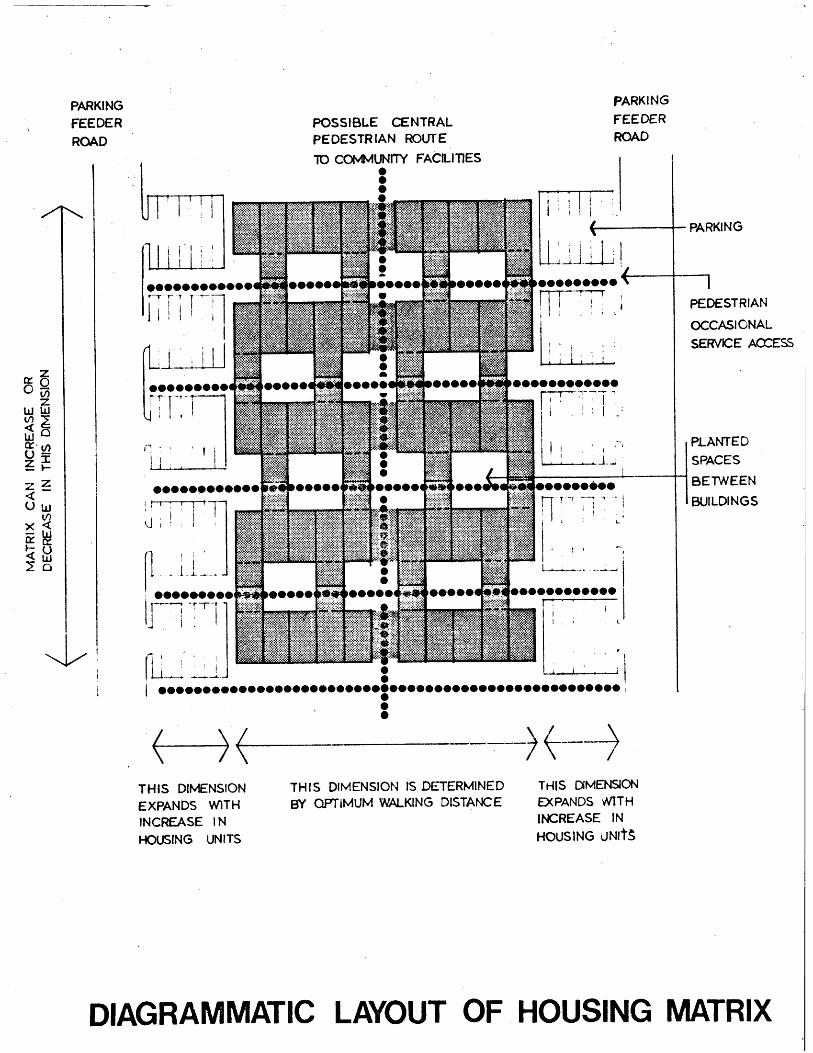
POSSIBLE CENTRALPEDESTRIAN ROUTE
TO COMMUNITY FACILITIES
PARKINGFEEDERROAD
PARKING
PEDESTRIAN
OCCASIONALSERVICE ACCESS
PLANTEDSPACES
BETWEEN
BUILDINGS
THIS DIMENSIONEXPANDS WITHINCREASE INHOUSING UNITS
THIS DIMENSION IS DETERMINEDBY QPTIMUM WALKING DISTANCE
THIS DiMENSIONEXPANDS WITHINCREASE INHOUSING UNItS
DIAGRAMMATIC LAYOUT OF HOUSING MATRIX
PARKINGFEEDERROAD

DIAGRAMATIC EXAMPLES OF HOUSING
TYPES: 20'-O"MODULE UNITS-39-

IB
V EXP
(.EXPI-
POSSIBLE FAMILY GROUPINGS20' UNIT MATRIX
-7
i~~1
IB B IB 2B 3B
3B2B IBE

EFFICIENCY APARTMENT ,
ONE BEDROOM APARTMENT
~TWO BEDROOM APARTMENT
THREE BEDROOM APARTMENT
CLOSET
[SHADED AREAS INDICATE POTENTIAL
EFABRICATED COMPONENTS
LEGEND
E
1B
2B
3B
C

io
.8/1-9
.9
.9 ,~I
--
-~-.
-~-
-
--
-. -.
--
-
-I-074
I-=0
119IZ
V1,9i
04
U.
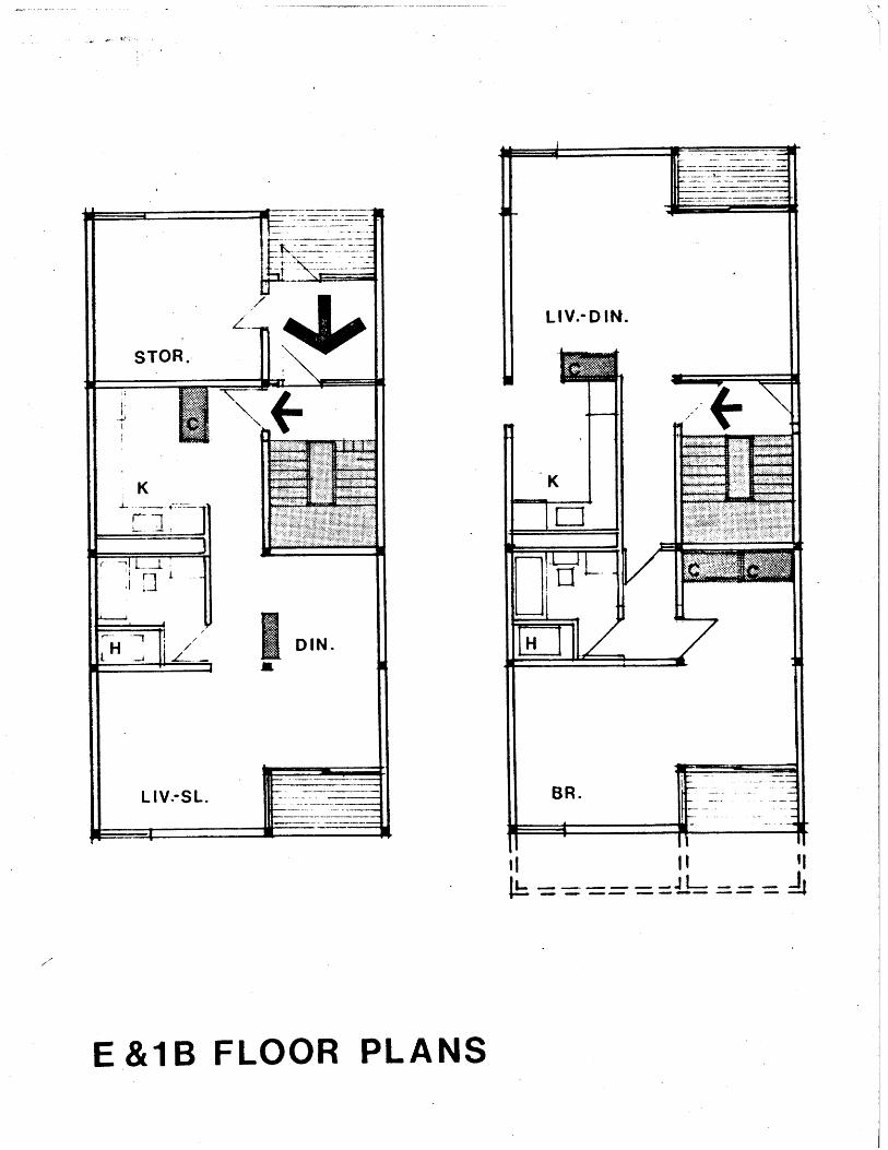
E&1B FLOOR PLANS

,7(C4
'0sk -
I-0..J

2B&3B FLOOR PLANS

2B -Jt V
I B
E
SECTION 3 STORY

3B
2B
IB
E
SECTION -4 STOR Y

DIAGRAMATIC EXAMPLES OF HOUSING
TYPES: 32a-O''-MODULE UNITS-48.

SPACE STANDARDS
It is suggested that another method. of reducing costs in
housing units is by examining present-day space standards.
Significant savings in low-cost housing can be achieved by
a reasonable reduction in these standards. The following
plans are based on English space standards currently
recommended as minimum standards.

IB 2B
EXP EXP
--
L1
E E IB IB IB 2B
EXP EXP
POSSIBLE FAMILY GROUPINGS32' UNIT MATRIX
L
E 3BEIB

60412@ 6 B' 6ON
-440
4
STRUCTURAL LAYOUT
6,4z121T1

1---tas
LIV.-DIN. LIV.-DIN -SL.
K K
BR. STOR.
1B&E FLOOR PLANS

I 2
STRUCTURAL LAYOUT
44'I,
4'
t4
4
C~4
4,
c~4
-4 -.4
--- iv-~7C
4'

1B&2B FLOOR PLANS
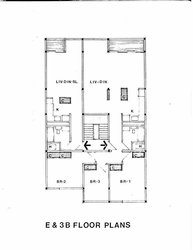
E&3B FLOOR PLANS

2B-IB -
IB-28
E-IBCINSO
SECTION 3 STORY

E-3B
IB-2B
IB-E
E
SECTION 4 STORY
DIAGRAMATIC EXAMPLES
TYPES:
OF HOUSING
TOWNHOUSE MODULE UNITS-58-

1ST FL.
SECTION
ii-
2 ND FL.
2B
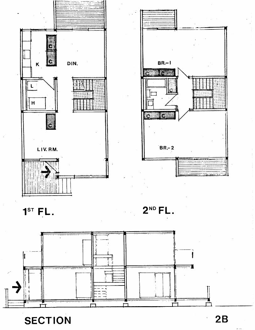
1ST FL.
SECTION
2 NDFL.
2B

1ST FL.
SECTION 3B
2 ND FL .
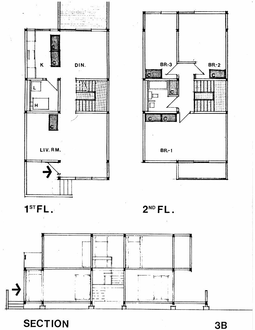
1STFL. 2 ND FL.
SECTION 3B

APPENDIX 1
MECHANICAL SYSTEMS DEVELOPED
FOR ILLUSTRATED HOUSE TYPES
HEATING
PLUMBINGELECTRICAL

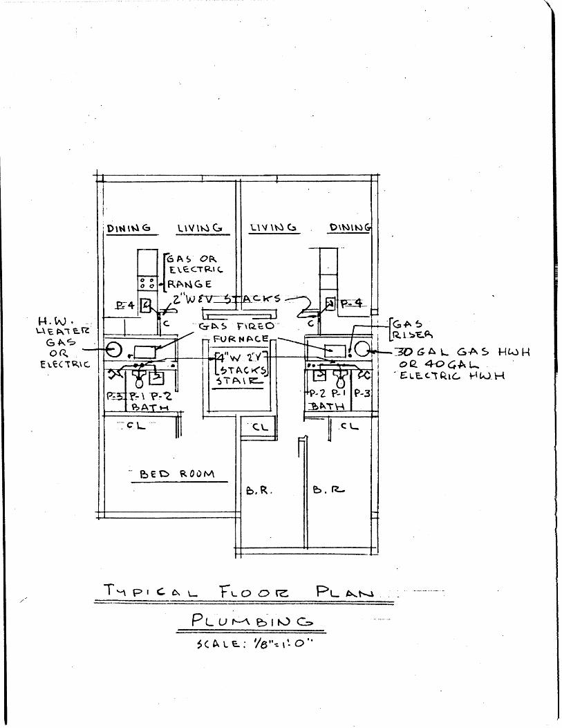
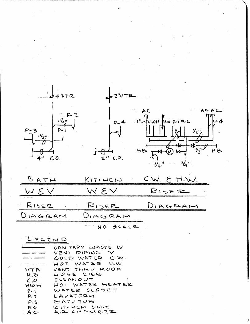
PLUMBING
The basic design of plumbing is in accordance with the
"Recommended Minimum Requirements For Plumbing" (Hoover
Report) as published by the United States Department of
Commerce. Consequently, all sanitary piping is not only
inexpensive, but, as can be observed by inspection of the
drawings, also lends itself in its simplicity to installa-
tion by unskilled labor. In single family isolated units,
and where there is no incentive towards inclusion of hot
water, individual hot water heaters are installed in each
unit. Hot water heaters may be gas or electric as dictated
by fuel and energy costs at each specific location. Where
rent inclusion of hot water is permitted in multiple
occupancy units, further economies can be realized by pro-
viding one hot water heater per building in lieu of one
hot water heater per dwelling unit. Piping materials can be
ferrous, nonferrous metal, or synthetic as indicated at each
location by availability, adaptability, acceptance, and cost.

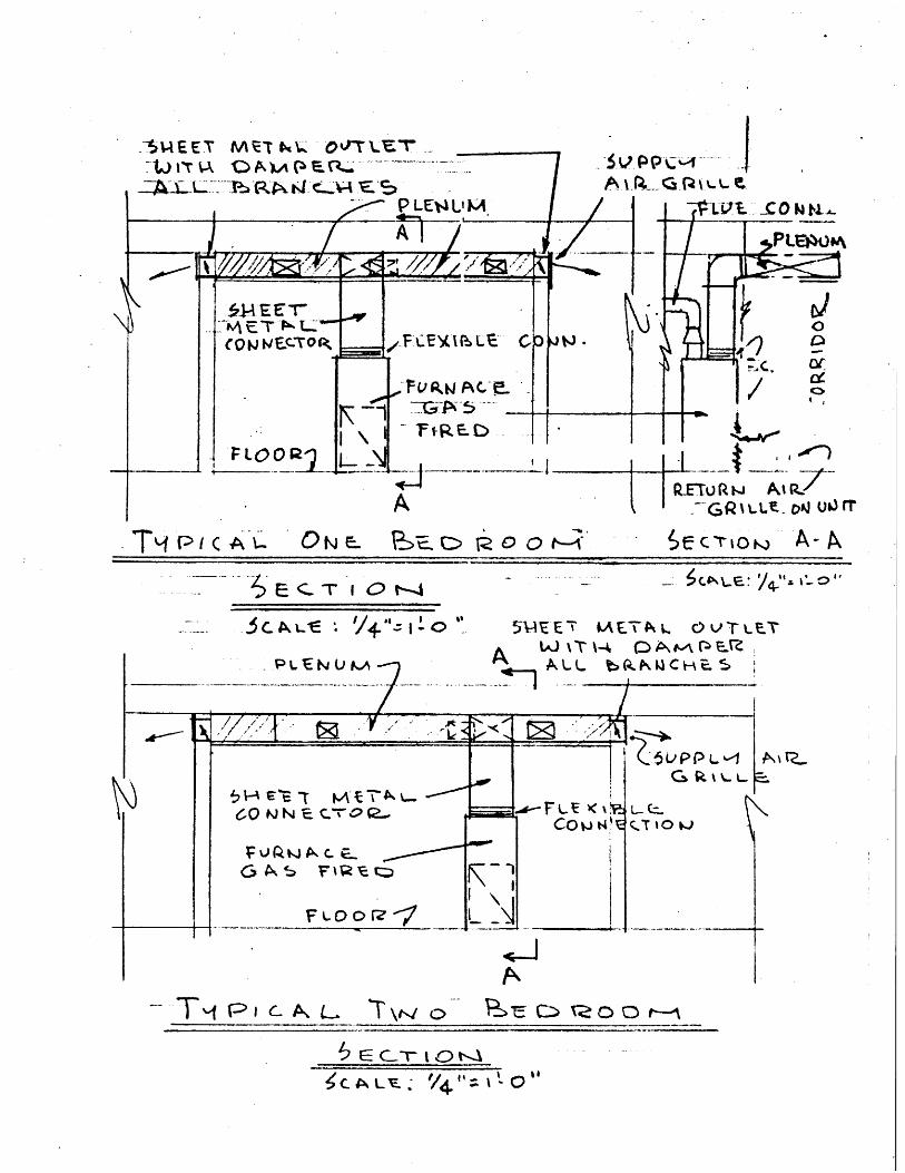
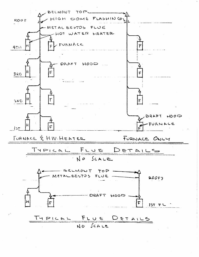
HEATING AND VENTILATION
Heating of each apartment is accomplished by a warm air
furnace located in each unit and discharging directly into
a ceiling plenum. The plenum is fabricated under the general
construction, thus avoiding sheet metal work. The system can
utilize fossil fuel or electricity as a source of heat as
dictated by economic analysis at each location. The system
requires no skilled labor to assemble in the field. Techni-
cians are required only during initial firing where fossil
fuels are incorporated. and. not at all where electric heat is
utilized. Each apartment will have its own thermostatic control.
Interior bathrooms are exhausted. through shafts constructed. in
the general construction and topped by wind-driven turbine
exhausters. Interior stairways are also similarly ventilated.
bymeans of wind-driven turbines at the top of the staircase.
Both.avoid expensive wiring, fans, and. maintenance. Accordingly,
installation of the heating system consists primarily of
setting a single factory assembled warm air heating unit in
place. Sheet metal duct work is almost non-existent. The
heating system lends itself readily to rent inclusion of hot
water or to individual metering as may be desired. It also
lend-s itself to future installation of mechanical cooling.
-65-
ELECTRICAL
All wiring conforms to the requirements of the National
Electrical Code. Individual fuse boxes in each apartment
permit convenient servicing of the system by each tenant
as well as individual or master metering of electrical
consumption. Cooking can be electric or gas. Branch
wiring is inexpensive aluminum not metallic sheathed cable.
Telephone system can be readily prewired in the construction.

-+ 14J UtVT
PNA- -tQQo r
Ie.
7VJiIly A 0 , A~ -VA
T4~- P I (A* S e " 1 ,-j
- ~E~TiQt~-4
5V-AIE E 7
-PLIEN4U &~A7-LAETPk L ThV-LP-
A ~C(~
-p ___________
6Q IJ%- t,
60~c~.~
wA~ C.et-.? F ~ % E
§1
IEcc) vi
QG V -- z
lcT to wJ
9IL \L '-p \f%.1 . 0 0 -
-.A-1\
~i <'I' I' m Y .11' 11
-A - -
V4
_:, CLA, LE - V4!'- I '- 0 "
IILL
e~ L M 0 11T -rO V::'
E T A L u PE tTO 5
Fu~wNc-L~ 0 ... 0t.
r - T TO
j A ~C) --
F L Q-Pk
T-i v->
0 Ck, is N= 7% VA 0 0 C:>
C> R 46 1: N wo 0
T7 L
VA vv -" E 1 ,. -t E- t L.

T- lati CE R A% 6 t
U3(9
&rtA ~TE
b.
TM pics\L-
.AL LCt~ S q_ AI T P~pJ~S~A. O~~1 _______c.
"AOT WPTR \V-s
No ~
C
cik% DI W4
30 GA L GA 5 HL0H
OE.CTCQIC, Ok. H
"FL 0 0 r.
PL u >I cK) ,
3 C A L '-: '/6--l'-o''
E%. tRCTc
T-- pi
}4"VTC~..
I4-2VF~-
- -
Pow5
4.P-
4 it c.o 2, C.O'.
P> N V-4 Kv& w t. -v ,-
R1<> EP D IPcxA -
- C O., ~ c C\
A~~~ L/T C=)%J- T W-. C, W
P- AT W -r -- W-
vA W TL 00 .
CvW. t xJ

'Vt
~.P-*?~
IIT,
e-3
p~3 U]
'' fVT rZ
A C- AC, Ac-
Is'-
-
P-I
P.- P-2
-J4
P-4
AC--9 21 n.- Ac
I" -W PF-I ?- 2. P-4--
Ac.. '' AL Ac-
AC.
P-3
"M T E Tr.
\d E \/ RveWz EA/ NA/ R ja CVW .. a H J.D I A C A,
5E~.b AT - 5
kw Au na to A T a \
COLO W EQ C-- - - \/ j!T >P. T /-4
\/TZ VENT TrW 2007H 6 Wo 0SE- e.. %;!>e,C.O0. C-- A u -
" w H w TkAE ?--\.A A ERP-3
-.4A c..
L AT/ P.. 0E~4
LAVATOLARrZ%4 A T C T- U- t:> I
A I r> c p A M il EE,
'2' i A e A c.
'T c-s k4 a P, mF'A t.--A

4;-%WGLC- 9CLe S',*417C"
U6WTIQC> MTe,.)
OU17LC-.*AeA6.%JC-->F-PUL u cHxjtj
5C-ALC-: ' ""If-C)"vs
F-0
FLo c) 1;;>TY T-.-- I ct -L F,L A, V.-I

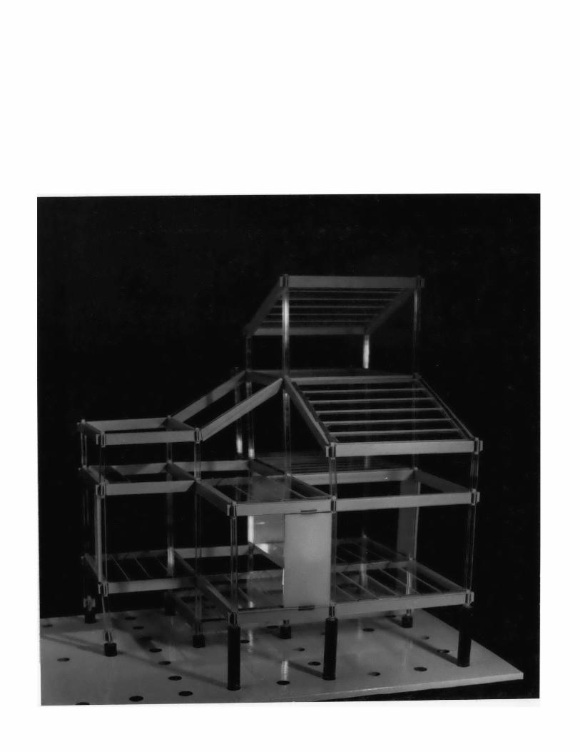
PHOTOGRAPHS OF MODELS-75-

I


e- -- - - -

-BIBLIOGRAPHY-80-

BIBLIOGRAPHY
Thomas Schmid/Carlo Testa, SystemsBuild.ing--An International
Survey of Methods, Frederick A. Praeger Publishing Company, 1969.
"Aesthetics and. Technology of Preassembly", Progressive
Architecture, October 1964.
"Metals Review", Progressive Architecture, October 1969.
Don Raney and Suzanne Stephens, "Operation Breakthrough--Opera-
tion P/R", Progressive Architecture, Pagesl20-137, April 1970.
Wells and Koetter, "Modular Housing System", Progressive
Architecture, Pages 86-87, January 1971.
Helmot E. Schultz, "Structure for Change and Growth", The
Architectural Forum, Pages 60-63, March 1971.
Special Issue on Build.ing Subsystems, Building Design and
Construction, September 1971.
"Building Systems", Engineering New Record, McGraw-Hill Pub-
lishing Company, October 22, 1970.
"Housing Systems Propoposals For Operation Breakthrough",
U.S. Department of Housing and. Urban Development, U. S. Govern-
ment Printing Office, December 1970.
"Modular Assembly (The Art of Design with Standardized. Parts)",
Progressive Architecture, November 1957.N ~0*

"Britain's Clasp System", The Architectural Forum, Pages 116-
123, November 1961.
"Unskilled Mass Production of Housing Proposed For Type B
Contract", submitted. in response to RFP #H-55-69 for Operation
Breakthrough H.U.D. Proposal prepared. by Imre and. Anthony
Halasz, Inc. and various other participants.
"Wheeling Steel Framing", catalogue of structural framing by
Wheeling Corrugating Company.
Stressed Skin Panels, catalogue of plywood components by
Plywood Fabricator Services, Inc.
Strong Tie Connector, Structural Design and Load Values,
Simpson Company.
-82-