oper ator s manual1).pdf · oper ator s manual ... do not go closer than the minimum safe approach...
TRANSCRIPT

Part Number 0075239EEJuly, 2005
OperOperOperOperOperaaaaator’tor’tor’tor’tor’sssssManualManualManualManualManual
View thousands of Crane Specifications on FreeCraneSpecs.comView thousands of Crane Specifications on FreeCraneSpecs.com

The aerial platform is not electrically insulated. Death or serious injury will result from con-tact with, or inadequate clearance from, an energized conductor.
Do not go closer than the minimum safe approach distance as defined by the Minimum SafeApproach Distance section in Chapter 3 – Safety.
Regard all conductors as energized.
Allow for electrical wire sag and aerial platform sway.
If the platform, booms, or any part of the aerial platform contacts a high-voltage electrical conductor,the entire machine can become electrically charged.
If that happens, remain on the machine and do not contact any other structure or object. This includesthe ground, adjacent buildings, poles, and any other objects that are not part of the aerial platform.
Such contact could make your body a conductor to the other object, creating an electrical shockhazard resulting in death or serious injury.
If an aerial platform is in contact with an energized conductor the platform operator must warn groundpersonnel in the vicinity to stay away. Their bodies can conduct electricity creating an electrical shockhazard resulting in death or serious injury.
Do not approach or leave the aerial platform until the electricity has been turned off.
Do not attempt to operate the lower controls when the platform, booms, or any part of the aerialplatform is in contact with a high-voltage electrical conductor or if there is an immediate danger of suchcontact.
Personnel on or near an aerial platform must be continuously aware of electrical hazards, recognizingthat death or serious injury can result from contact with an energized conductor.
View thousands of Crane Specifications on FreeCraneSpecs.comView thousands of Crane Specifications on FreeCraneSpecs.com

TB47J – 0075239EE
Table of Contents
Chapter 1 – IntroductionAerial Platform Features ............................................ 1Options ..................................................................... 1Operator’s Manual ..................................................... 1Safety Alerts ............................................................. 1Operation .................................................................. 1Maintenance ............................................................. 2Owner and User Responsibilities ............................... 2Additional Information ................................................ 2
Chapter 2 – SpecificationsComponent Identification ........................................... 3Working Envelope ..................................................... 4General Specifications ............................................... 5
Aerial Platform ........................................................ 5Platform .................................................................. 5Function Speed .......................................................5Drive System ..........................................................5Tires ....................................................................... 5Electrical System ................................................... 5Hydraulic System ................................................... 5Engine .................................................................... 5Fuel Tank Capacity .................................................5Ambient Air Temperature Operating Range .............. 5Maximum Wind Speed ............................................ 5
Engine Specifications ................................................ 6Engine Oil Viscosity.................................................. 7
Cummins B3.3 ........................................................ 7Deutz F3L-2011F ....................................................7
Chapter 3 – SafetyElectrocution Hazards ............................................... 9Minimum Safe Approach Distance............................. 9Prestart Inspection ...................................................10Work Place Inspection and Practices .......................10Operation .................................................................10Tip-Over and Falling Hazards ....................................10Electrical System..................................................... 11Hydraulic System..................................................... 11Engine and Fuel Handling Precautions ..................... 11Placards and Decals ................................................12
Chapter 4 – Safety DevicesEmergency Stop Controls ........................................13Emergency Power System .......................................13Emergency Lowering Knob .......................................13Ground Operation Switch .........................................14Platform Foot Switch ................................................14Guardrails ................................................................14Lanyard Anchors ......................................................14Tilt Alarm ..................................................................14Platform Overload Sensing System ..........................15
Engine Protection Systems......................................15High Engine Temperature Alarm ............................ 15Low Oil Pressure Alarm ........................................ 15
Horn .........................................................................16Drive Motion Alarm ...................................................16Flashing Light ..........................................................16Driving Lights............................................................16Platform Work Lights ...............................................16
Chapter 5 – Gauges and DisplaysHour Meter ...............................................................17Engine Temperature Gauge ......................................17Ammeter ..................................................................17Engine Air Filter Gauge ............................................17Fuel .........................................................................17Engine Oil ................................................................18Hydraulic Fluid Filter Gauge .....................................18Fluid Level and Temperature Gauge ..........................18
Chapter 6 – ControlsBattery Disconnect Switch .......................................19Lower Controls .........................................................19
Emergency Stop Button ........................................ 19Control Selector Switch ........................................ 19Start Switch .......................................................... 19Ground Operation Switch ...................................... 20Rotation Switch ..................................................... 20Boom Elevation Switch ......................................... 20Boom Extend/Retract Switch ................................ 20Jib Articulation Switch ........................................... 20Platform Level Switch ............................................ 20Platform Rotation Switch ....................................... 20Engine/Emergency Power Switch ......................... 20Throttle Switch ...................................................... 20Circuit Breaker Reset Buttons ............................... 20
Upper Controls .........................................................21Start Switch .......................................................... 21Emergency Stop Button ........................................ 21Speed Knob .......................................................... 21Drive/Boom Selector Switch .................................. 22Boom Joystick ...................................................... 22Drive Joystick ....................................................... 22Drive Range Switch ............................................... 22Jib Articulation Switch ........................................... 22Boom Extend/Retract Switch ................................ 22Platform Rotate Switch ......................................... 22Platform Level Switch ............................................ 22Engine/Emergency Power Switch ......................... 22Throttle Switch ...................................................... 22Horn Button .......................................................... 23Platform Foot Switch ............................................. 23
Machine/Generator Switch .......................................23Driving and Platform Work Lights..............................23
View thousands of Crane Specifications on FreeCraneSpecs.comView thousands of Crane Specifications on FreeCraneSpecs.com

Table of Contents
TB47J – 0075239EE
Chapter 7 – Prestart InspectionOperator’s Manual ....................................................25Engine .....................................................................25
Oil Level ................................................................ 25Coolant ................................................................. 25Radiator ................................................................ 26Fuel Tank .............................................................. 26Fuel Line ............................................................... 26Air Filter ................................................................ 26Charging System .................................................. 26Cold Weather Start Kit—Block Heater................... 26
Electrical System.....................................................26Emergency Power Battery .................................... 27Battery Fluid Level ................................................ 27Battery Terminals .................................................. 27
Cables and Wiring Harness ......................................27Hydraulic System.....................................................27
Fluid Level............................................................. 27Fluid Filter............................................................. 28Hoses, Tubes, and Fittings ................................... 28
Tires and Wheels .....................................................28Lower Control Station ...............................................28
Operating Controls ................................................ 29Emergency Stop ................................................... 29Emergency Power................................................. 29
Emergency Lowering ................................................29Level Sensor ............................................................29Flashing Light ..........................................................30Sandblast Protection Kit ..........................................30Structures ................................................................30
Weldments ........................................................... 30Slide Pads ............................................................ 30Wire Ropes ........................................................... 30Fasteners ............................................................. 31
Upper Control Station ...............................................31Guardrail System .................................................. 31Lanyard Anchors ................................................... 32Operating Controls ................................................ 32Emergency Stop ................................................... 32Emergency Power................................................. 32Horn ...................................................................... 32Electrical Power Outlet ......................................... 32Drive Motion Alarm ................................................ 32Driving and Work Lights ........................................ 32Platform Control Cover .......................................... 32
Tow Kit .....................................................................32
Placards and Decals ................................................33Prestart Inspection Checklist ...................................37
Chapter 8 – OperationCold Weather Start-Up .............................................39Engine Cold Weather Start Kit ..................................39
Cummins — Block Heater .................................... 39Deutz — Manifold Preheater ................................. 39
Hydraulic System Cold Weather Warm-Up...............39Preparing for Operation.............................................40Lower Controls .........................................................40Upper Controls .........................................................40
Boom Operation .................................................... 41Platform Overload Sensing System ....................... 41Driving and Steering .............................................. 42Drive Speeds ......................................................... 42Motion Warning Alarm ........................................... 43
Four Wheel Drive ......................................................43AC Generator ...........................................................43Air Line ....................................................................43Driving Lights............................................................43Platform Work Lights ...............................................43
Chapter 9 – Stowing and TransportingStowing ....................................................................45
Tucked Stow ......................................................... 45Transporting .............................................................45
Driving ................................................................... 46Winching .............................................................. 46Hoisting ................................................................ 47Securing for Transport ........................................... 48
Chapter 10 – Emergency OperationEmergency Power System .......................................49
Lower Controls ...................................................... 49Upper Controls ...................................................... 49
Emergency Lowering ................................................50Towing ......................................................................50
Chapter 11 – TroubleshootingTroubleshooting Chart ..............................................53
Appendix A – Glossary
Limited Warranty
View thousands of Crane Specifications on FreeCraneSpecs.comView thousands of Crane Specifications on FreeCraneSpecs.com

TB47J – 0075239EE 1
Chapter 1 – Introduction
Aerial Platform FeaturesThe aerial platform is a boom-supported elevating workplatform used to raise personnel, their tools, and mate-rial to the workstation. The booms are raised and low-ered with hydraulic cylinders. Hydraulic motors on thedrive wheels provide power to move the aerial platform.
The standard machine includes the following features.
• Proportional boom lift, swing, and drive control • 170 degree hydraulic platform rotation • Two safety lanyard attachments • Manual lowering valve at chassis • Hydraulic oil level and temperature gauges • Lifting lugs • Tie-down lugs • Horn • 3.5 degree tilt alarm • Electronic ignition • Hour meter • Ammeter • Coolant temperature gauge • High engine temperature shut down • Low oil pressure shut down • Foam filled tires • Battery operated emergency power system • 360 degree continuous turntable rotation • 76 cm x 152 cm (30″ x 60″) steel platform • Platform gravity gate • Platform overload sensing system • Five year limited warranty
The machine may be powered with one of the followingengines.
• Cummins B3.3 – Diesel • Deutz F3L-2011F – Diesel
The aerial platform has been manufactured to conform toEuropean Directive 98/37/EC and European StandardEN280.
OptionsThe following options may be provided on the machine. • Platform control cover • Platform work lights – flood lights • Flashing light – amber • Platform swinging gate • Sandblast protection kit • Driving lights – two headlights and two rear lights • Spark arrestor muffler – Deutz engines • Cold weather start kit Cummins – block heater • Cold weather start kit Deutz – manifold preheater • AC generator – hydraulic powered, 220 VAC • Drive motion alarm • Road tread tires • Flotation tires • Airline to platform • Tow kit
• 76 cm x 234 cm (30″ x 92″) aluminum 226 kg (500 lb)capacity platform
• 76 cm x 152 cm (30″ x 60″) aluminum 272 kg (600 lb)capacity platform
Operator’s ManualThis manual provides information for safe and proper op-eration of the aerial platform. Read and understand theinformation in this Operator’s Manual before operatingthe aerial platform on the job.
Additional copies of this manual may be ordered fromSnorkel. Supply the model and manual part number fromthe front cover to assure that the correct manual will besupplied.
All information in this manual is based on the latest prod-uct information at the time of publication. Snorkel reservesthe right to make product changes at any time withoutobligation.
Safety AlertsA safety alert symbol is used throughout this manual toindicate danger, warning, and caution instructions. Fol-low these instructions to reduce the likelihood of per-sonal injury and property damage. The terms danger,warning, and caution indicate varying degrees of personalinjury or property damage that can result if the instruc-tion is not followed.
ADangerIndicates an imminently hazardous situation which,if not avoided, will result in death or serious injury.This signal word is to be used in the most extremesituations.
AWarningIndicates a potentially hazardous situation which, ifnot avoided, could result in death or serious injury.
ACautionIndicates a potentially hazardous situation which, ifnot avoided, may result in minor or moderate in-jury. It may also be used to alert against unsafepractices.
NotesNotes are used to provide special information or helpfulhints to assist in aerial platform operation, but do notindicate a hazardous situation.
OperationThe aerial platform has built-in safety features and hasbeen factory tested for compliance with Snorkel specifi-cations and industry standards. However, any personnellifting aerial platform can be potentially dangerous in thehands of untrained or careless operators.
View thousands of Crane Specifications on FreeCraneSpecs.comView thousands of Crane Specifications on FreeCraneSpecs.com

Chapter 1 – Introduction
2 TB47J – 0075239EE
AWarningThe potential for an accident increases when theaerial platform is operated by personnel who arenot trained and authorized. Death or serious injurycan result from such accidents. Read and under-stand the information in this manual and on the plac-ards and decals on the machine before operatingthe aerial platform on the job.
Training is essential and must be performed by a quali-fied person. Become proficient in knowledge and actualoperation before using the aerial platform on the job. Youmust be trained and authorized to perform any functionsof the aerial platform. Operation of the aerial platform mustbe within the scope of the machine specifications.
The operator bears ultimate responsibility for following allmanufacturer’s instructions and warnings, regulations andsafety rules of their employer and/or any state or federallaw.
MaintenanceEvery person who maintains, inspects, tests, or repairsthe aerial platform must be qualified to do so. Followingthe daily prestart inspection in this Operator’s Manualwill help keep the aerial platform in optimum working con-
dition. Other maintenance functions must be performedby maintenance personnel who are qualified to work onthe aerial platform.
Do not modify this aerial platform without prior writtenconsent of the Snorkel Engineering Department. Modifi-cation may void the warranty, adversely affect stability,or affect the operational characteristics of the aerial plat-form.
Owner and User ResponsibilitiesAll owners and users of the aerial platform must read,understand, and comply with all applicable regulations.Ultimate compliance to national safety regulations is theresponsibility of the user and their employer.
Additional InformationFor additional information contact your local dealer orSnorkel at:
Snorkel InternationalP.O. Box 1160St. Joseph, MO 64502-1160 USA785-989-3000
http://www.snorkelusa.com
View thousands of Crane Specifications on FreeCraneSpecs.comView thousands of Crane Specifications on FreeCraneSpecs.com
TB47J – 0075239EE 3
Chapter 2 – Specifications
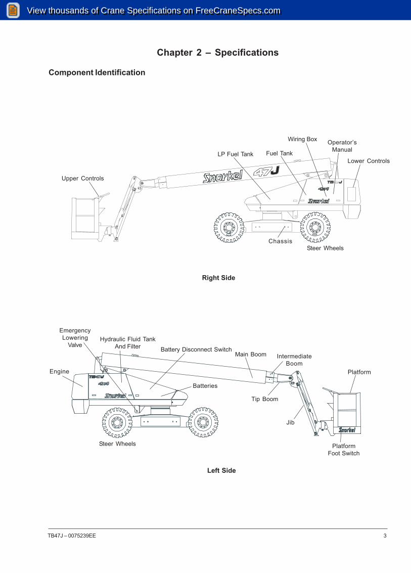
Component Identification
Right Side
Chassis
Lower Controls
Upper Controls
Fuel Tank
Wiring Box Operator’sManual
LP Fuel Tank
Steer Wheels
Left Side
Platform
Main Boom
Tip Boom
Hydraulic Fluid TankAnd Filter Battery Disconnect Switch
Batteries
Engine
Steer Wheels PlatformFoot Switch
EmergencyLowering
Valve
IntermediateBoom
Jib
View thousands of Crane Specifications on FreeCraneSpecs.comView thousands of Crane Specifications on FreeCraneSpecs.com

Chapter 2 – Specifications
4 TB47J – 0075239EE
Working Envelope
Meters(Feet)
9.1(30)
6.1(20)
3.0(10) 0
3.0(10)
12.2(40)
0
3.0(10)
6.1(20)
9.1(30)
12.2(40)
15.2(50)
75°
18°
70°
70°
View thousands of Crane Specifications on FreeCraneSpecs.comView thousands of Crane Specifications on FreeCraneSpecs.com

Chapter 2 – Specifications
TB47J – 0075239EE 5
General Specifications
Aerial PlatformWorking height 16 m (52′ 6″)Maximum platform height 14.2 m (46′ 6″)Horizontal reach 11.9 m (39′)Main boom Articulation -18° to +75° Extension 2.5 m (8′ 4.75″)Turntable rotation 360° continuousTurning radius, inside Two wheel drive 1.6 m (5′ 2″) Four wheel drive 1.7 m (5′ 6″)Wheelbase 2.4 m (8′)Ground clearance 25 cm (10″)Maximum wheel load 2,495 kg (5,500 lbs)Maximum ground pressure 3.8 kg/cm² (54 psi)Weight, GVW Approximate 6,123 kg (13,500 lbs)Stowed width 2.4 m (7′ 11.5″) With flotation tires 2.6 m (8′ 7.5″)Stowed length 8.1 m (26′ 9″)Stowed length, tucked stow 6.5 m (21′ 3.5″)Stowed height 2.3 m (7′ 9″)Stowed height, tucked stow 2.4 m (7′ 11.5″)
PlatformDimensions Standard steel 76 cm x 152 cm (30″ x 60″) Rated work load 227 kg (500 lb) Optional aluminum 76 cm x 234 cm (30″ x 92″) Rated work load 227 kg (500 lb) Optional aluminum 76 cm x 152 cm (30″ x 60″) Rated work load 227 kg (600 lb)Rotation 90° CW to 80° CCWMaximum number of occupants 2 peopleOptional AC generator 220 VAC
Function SpeedTurntable rotation, 360 degrees 108 to 113 secondsMain boom Up 65 to 70 seconds Down 65 to 70 seconds Extend 40 to 45 seconds Retract 25 to 30 secondsJib Up 25 to 35 seconds Down 25 to 35 secondsPlatform rotation, 170 degrees 8 to 15 secondsDrive High, booms stowed 4.8 km/h (3.0 mph) Low, booms elevated 1.6 km/h (1.0 mph)
Drive SystemStandard Four wheel driveOptional Two wheel driveGradeability 25%
TiresStreet tread, 10 ply 30 cm x 42 cm (12″ x 16.5″)Bar lug, 10 ply 30 cm x 42 cm (12″ x 16.5″)Flotation, 10 ply 33/16LL-16.1Foam filled, 10 ply Street tread or bar lug
Electrical SystemVoltage 12 V DC negative chassis groundSource Two - 12 V 600 CCA batteriesFluid recommended distilled water
Hydraulic SystemMaximum pressure 20,684 kPa (3,000 psi)Reservoir capacity 62.4 l (16.5 US gal)System capacity 94.6 l (25 US gal)Maximum operating temperature 93°C (200°F)Hydraulic fluid recommended Above -13°C (10°F) Mobil DTE-13M
(ISO VG32) Below -13°C (10°F) Mobil DTE-11M
(ISO VG15)
EngineDiesel Cummins B3.3Diesel Deutz F3L-2011F
Fuel Tank CapacityDiesel 75.7 l (20 US gal)
Ambient Air Temperature Operating RangeCelsius -18°C to 43°CFahrenheit 0°F to 110°F
Maximum Wind SpeedGust or steady 45 km/h (28 mph)
View thousands of Crane Specifications on FreeCraneSpecs.comView thousands of Crane Specifications on FreeCraneSpecs.com

Chapter 2 – Specifications
6 TB47J – 0075239EE
Engine Specifications
Note 1: Refer to the engine manufacturers manual for specific fuel recommendations and specifications.
Note 2: Ethylene glycol or Propylene glycol may be used. Refer to the Cummins® Operation and Maintenance Manual B3.3 SeriesEngines for specific coolant recommendations and specifications.
Note 3: Refer to the engine manufacturers manual for specific lubricating oil recommendations and specifications.
CumminsB3.3
Diesel
DeutzF3L-2011F
Diesel
CID Fuel Grade CoolantOperating
TemperatureOil
Capacity
2.0 liter(125 cu. in.)
3.26 liter(199 cu. in.)
OilGradeEngine
ASTM No. 2D fuel with aminimum Cetane number of40.1 For operating tempera-tures below 0°C (32°F) use
winterized No. 2D.
• DIN 51 601 (February 1986).1
• BS 2869: A1 and A2 (with A2refer to Deutz manual aboutsulfur content)1
• ASTM D 975-88: 1-D and 2-D • CEN EN 590 or DIN EN 590 • NATO Code F-54 and F-75 • For operating temperatures
below 0°C (32°F) use wintergrade diesel.
Air
50% water50% Antifreeze2
6.0 liter(1.59 US gal)
API: CDor higher3
7.5 liter (2 gal)total
1.5 liter (1.6 qt)Low to High
SAE15W-403
API:CH4/SG
60°C to 100°C140°F to 212°F
78°C to 95°C172°F to 203°F
View thousands of Crane Specifications on FreeCraneSpecs.comView thousands of Crane Specifications on FreeCraneSpecs.com

Chapter 2 – Specifications
TB47J – 0075239EE 7
Engine Oil Viscosity
Cummins B3.3
Deutz F3L-2011F
View thousands of Crane Specifications on FreeCraneSpecs.comView thousands of Crane Specifications on FreeCraneSpecs.com

Chapter 2 – Specifications
8 TB47J – 0075239EE
View thousands of Crane Specifications on FreeCraneSpecs.comView thousands of Crane Specifications on FreeCraneSpecs.com

TB47J – 0075239EE 9
Chapter 3 – Safety
Knowledge of the information in this manual, and propertraining, provide a basis for safely operating the aerialplatform. Know the location of all controls and how theyoperate to act quickly and responsibly in an emergency.
Safety devices reduce the likelihood of an accident. Neverdisable, modify, or ignore any safety device. Safety alertsin this manual indicate situations where accidents mayoccur.
If any malfunction, hazard or potentially unsafe conditionrelating to capacity, intended use, or safe operation issuspected, stop aerial platform operation and seek as-sistance.
The operator bears ultimate responsibility for following allmanufacturer’s instructions and warnings, regulations andsafety rules of their employer and/or any state or federallaw.
Electrocution HazardsThe aerial platform is made of metal components and isnot insulated. Regard all conductors as energized. Donot operate outside during a thunderstorm.
Minimum Safe Approach DistanceMinimum safe approach distances to energized powerlines and their associated parts must be observed whileoperating the aerial platform.
ADangerThe aerial platform is not electrically insulated.Death or serious injury will result from contact with,or inadequate clearance from, an energized con-ductor. Do not go closer than the minimum safe ap-proach distance as defined by ANSI.
ANSI publications define minimum distances that mustbe observed when working near bus bars and energizedpower lines. Table 1 and Figure 3 are reprinted courtesyof Scaffold Industry Association, ANSI/SIA A92.5
Table 1 – Minimum Safe Approach Distance
Figure 3 – Minimum Safe Approach Distance
Minimum Safe Approach DistanceVoltage Range(Phase to Phase)
0 to 300VOver 300V to 50kVOver 50kV to 200kV
Over 200kV to 350kVOver 350kV to 500kV
Over 500kV to 750kVOver 750kV to 1000kV
Feet Meters
Avoid Contact1015
2520
3545
3.054.606.10
7.6210.6713.72
View thousands of Crane Specifications on FreeCraneSpecs.comView thousands of Crane Specifications on FreeCraneSpecs.com

Chapter 3 – Safety
10 TB47J – 0075239EE
Prestart InspectionPerform a prestart inspection before each shift as de-scribed in Chapter 7. Do not use the aerial platform onthe job unless you are trained and authorized to do so.
Work Place Inspection and PracticesDo not use the aerial platform as a ground connectionwhen welding. The welding ground clamp must be at-tached to the same structure that is being welded. Elec-trical current flow can be very intense, causing seriousinternal damage to some components.
Inspect the area before and during aerial platform use.The following are some potential hazards that may be inthe work place.
• Debris • Slopes • Drop-offs or holes • Bumps and floor obstructions • Overhead obstructions • Unauthorized persons • High voltage conductors • Wind and weather conditions • Inadequate surface and support to withstand load
forces applied by the aerial platform in all operatingconfigurations
Before using the aerial platform in any hazardous (classi-fied) location, make certain it is approved and of the typerequired by ANSI/NFPA 505 for use in that particular lo-cation.
Know and understand the job site traffic-flow patterns andobey the flagmen, road signs, and signals.
While operating the aerial platform, a good safety prac-tice is to have qualified personnel in the immediate workarea to:
• Help in case of an emergency. • Operate emergency controls as required. • Watch for loss of control by platform operator. • Warn the operator of any obstructions or hazards
that may not be obvious to them. • Watch for soft terrain, sloping surfaces, drop-offs,
etc. where stability could be jeopardized. • Watch for bystanders and never allow anyone to be
under, or to reach through the booms while operatingthe aerial platform.
ADangerPinch points may exist between moving compo-nents. Death or serious injury will result from be-coming trapped between components, buildings,structures, or other obstacles. Make sure there issufficient clearance around the machine beforemoving the chassis, booms, or platform. Allow suffi-cient room and time to stop movement to avoid con-tact with structures or other hazards.
Always look in the direction of movement. Drive with careand at speeds compatible with the work place conditions.Use caution when driving over rough ground, on slopes,and when turning. Do not engage in any form of horse-play or permit riders any place other than in the platform.
Secure all accessories, containers, tools, and other ma-terials in the platform to prevent them from accidentallyfalling or being kicked off the platform. Remove all ob-jects that do not belong in or on the aerial platform.
Never steady the platform by positioning it against an-other platform.
Do not operate the aerial platform if it is damaged or notfunctioning properly. Qualified maintenance personnelmust correct the problem before putting the aerial plat-form back into service.
OperationUse three points of support when entering or exiting theplatform. For example, use two hands and one foot whenclimbing into the platform.
Never cover the platform floor grating or otherwise ob-struct your view below. Make sure the area below theplatform is free of personnel before lowering.
Keep both feet positioned firmly on the platform floor.Operate the controls slowly and deliberately to avoid jerkyand erratic operation. Always stop the controls in neutralbefore going in the opposite direction.
Do not dismount while the aerial platform is in motion orjump off the platform.
Properly stow the aerial platform and secure it againstunauthorized operation at the end of each work day, be-fore transporting, or if it is left unattended.
Tip-Over and Falling HazardsOperate the aerial platform only on a firm, flat, level sur-face capable of withstanding all load forces imposed bythe aerial platform in all operating conditions. Refer to theGeneral Specifications chart for the maximum wheel loadand ground pressure. Raise the booms only when theaerial platform is on level ground.
ADangerThe aerial platform can tip over if it becomes un-stable. Death or serious injury will result from a tip-over accident. Do not drive or position the aerialplatform for elevated use near any drop-off, hole,slope, soft or uneven ground, or other tip-over haz-ard. Do not raise the boom in winds above 45 km/h(28 mph).
All platform occupants must wear a fall restraint deviceconnected to a lanyard anchor point.
View thousands of Crane Specifications on FreeCraneSpecs.comView thousands of Crane Specifications on FreeCraneSpecs.com

Chapter 3 – Safety
TB47J – 0075239EE 11
It is best not to transfer from the platform to another struc-ture or from the structure to the platform, unless that isthe safest way to do the job. Judge each situation sepa-rately taking the work environment into account. If it isnecessary to transfer from the platform to another struc-ture the following guidelines apply:
1. Where possible, place the platform over a roof orwalking structure to do the transfer.
2. Transfer your anchorage from one structure to theother before stepping across.
3. Remember that you might be transferring to a struc-ture where personal fall arrest is required.
4. Use the platform entrance, do not climb over orthrough the guardrails.
Do not operate the aerial platform in windy or gusty con-ditions. Do not add anything to the aerial platform thatwill increase the wind loading such as billboards, ban-ners, flags, etc.
Never operate the aerial platform without all parts of theguardrail system in place and the gate closed. Make surethat all protective guards, cowlings, and doors are se-curely fastened.
Do not exceed the platform capacity as indicated on theplatform rating placard on the platform. Do not carry loadsthat extend beyond the platform guardrails without priorwritten consent from Snorkel.
Do not operate the aerial platform from trucks, trailers,railway cars, floating vessels, scaffolds, or similar equip-ment unless the application is approved in writing bySnorkel.
Do not use the aerial platform as a crane, hoist, jack, orfor any purpose other than to position personnel, tools,and materials.
Do not climb on the guardrails or use ladders, planks, orother devices to extend or increase the work positionfrom the platform.
Take care to prevent rope, electrical cords, and hoses,etc., from becoming caught in or on the aerial platform. Ifthe platform or booms becomes caught on an adjacentstructure or other obstacle and is prevented from normalmotion, reverse the control to free the platform. If controlreversal does not free the platform, evacuate the platformbefore attempting to free it.
Electrical SystemCharge the batteries in a well-ventilated area free of flame,sparks, or other hazards that might cause fire or explo-sion.
Do not operate any of the aerial platform functions whilethe battery charger is plugged in.
AWarningBatteries give off hydrogen and oxygen that cancombine explosively. Death or serious injury couldresult from a chemical explosion. Do not smoke orpermit open flames or sparks when checking thebatteries.
Battery acid can damage the skin and eyes. Seri-ous infection or reaction can result if medical treat-ment is not given immediately. Wear face and eyeprotection when working near the batteries.
Batteries contain sulfuric acid that can damage your eyesor skin on contact. Wear a face shield, rubber gloves,and protective clothing when working around batteries. Ifacid contacts your eyes, flush immediately with clearwater and get medical attention. If acid contacts yourskin, wash off immediately with clear water.
Hydraulic SystemThe hydraulic system contains hoses with hydraulic fluidunder pressure.
ADangerHydraulic fluid escaping under pressure can haveenough force to inject fluid into the flesh. Seriousinfection or reaction will result if medical treatmentis not given immediately. In case of injury by escap-ing hydraulic fluid, seek medical attention at once.
Do not place your hand or any part of your body in front ofescaping hydraulic fluid. Use a piece of cardboard or woodto search for hydraulic leaks.
Engine and Fuel Handling PrecautionsRefer to the engine manufacturer’s Operator’s Manual forcomplete information on safe engine operation, mainte-nance, and specifications.
ADangerEngine exhaust contains carbon monoxide, a poi-sonous gas that is invisible and odorless. Breathingengine exhaust fumes will cause death or seriousillness. Do not run the engine in an enclosed areaor indoors without adequate ventilation.
Be careful not to run the diesel fuel tank empty. Bleedthe fuel system if air enters the lines between the tankand the injection pump.
Allow the engine to return to idle before shutting the en-gine off.
Do not smoke or permit open flames while fueling or nearfueling operations.
View thousands of Crane Specifications on FreeCraneSpecs.comView thousands of Crane Specifications on FreeCraneSpecs.com

Chapter 3 – Safety
12 TB47J – 0075239EE
Never remove the fuel cap or fill the fuel tank while theengine is running or hot. Never allow fuel to spill on hotmachine components.
Maintain control of the fuel filler nozzle when filling thetank. Spilled fuel is a potential fire hazard.
Do not overfill the fuel tank. Allow room for expansion.
Clean up spilled fuel immediately.
Tighten the fuel tank cap securely. If the fuel cap is lost,replace it with an approved cap from Snorkel. Use of anon-approved cap without proper venting may result inpressurization of the tank.
Never use fuel for cleaning purposes.
For diesel engines, use the correct fuel grade for theoperating season.
ACautionEngine coolant escaping under pressure can causeserious burns. Shut the engine off and let it coolbefore removing the radiator cap.
Let the engine and radiator cool before adding coolant.
Placards and DecalsThe aerial platform is equipped with placards and decalsthat provide instruction for operation and accident pre-vention. Do not operate the aerial platform if any plac-ards or decals are missing or not legible.
View thousands of Crane Specifications on FreeCraneSpecs.comView thousands of Crane Specifications on FreeCraneSpecs.com

TB47J – 0075239EE 13
This aerial work platform is manufactured with safety de-vices, placards, and decals to reduce the likelihood of anaccident. For the safety of all personnel, do not disable,modify, or ignore any safety device. Safety devices areincluded in the daily prestart inspection.
AWarningThe potential for an accident increases when safetydevices do not function properly. Death or seriousinjury can result from such accidents. Do not alter,disable, or override any safety device.
If any safety devices are defective, remove the aerial plat-form from service until qualified maintenance personnelcan make repairs.
Emergency Stop ControlsThere is an emergency stop control at the lower and up-per controls.
At the lower controls, the emergency stop is a two-posi-tion push button (refer to Figure 4.1). Push the emer-gency stop button in to disconnect power to all controlcircuits. Pull the button out to restore power.
Figure 4.1 – Lower Controls
NoteThe lower controls override the upper controls. If the up-per control emergency stop button is engaged, the lowercontrols can still be used to operate the aerial platform.
At the upper controls, the emergency stop is a two-posi-tion push button (refer to Figure 4.2).
Figure 4.2 – Upper Controls
Push the emergency stop button in to disconnect powerto the upper control circuits. Pull the button out to re-store power.
Emergency Power SystemThe emergency power system includes a back-up pump,motor, and battery. Use this system to operate the boomand turntable functions to lower the platform if the mainpower system fails due to engine or pump failure. Holdthe engine/emergency power switch (refer to Figure 4.1and 4.2) down to activate the emergency power system.
The length of time the pump can be operated depends onthe capacity of the battery.
Emergency Lowering KnobThe emergency lowering knob may be used to lower thebooms if the engine will not start and the emergencypower system will not work. The knob is on the base endof the main boom lift cylinder (refer to Figure 4.3) underthe left side of the turntable.
Figure 4.3 – Emergency Lowering Knob
Chapter 4 – Safety Devices
EmergencyLowering Knob
EmergencyStop Button
Ground OperationSwitch
Engine/EmergencyPower Switch
EmergencyStop Button
Engine/EmergencyPower Switch
View thousands of Crane Specifications on FreeCraneSpecs.comView thousands of Crane Specifications on FreeCraneSpecs.com

Chapter 4 – Safety Devices
14 TB47J – 0075239EE
The gates close automatically after entering or exitingthe platform. The gate is part of the guardrail system andmust be securely fastened after entering the platform.
Lanyard AnchorsTwo lanyard anchors for fall restraint anchorage are pro-vided below the upper controls at the front of the platform(refer to Figure 4.4).
NoteThe lanyard anchors are not for lifting or tying the ma-chine down.
All personnel in the platform must connect their fall re-straint device to a lanyard anchor before raising the plat-form. Do not use the aerial platform for personal fall ar-rest anchorage.
Tilt AlarmIf the aerial platform chassis is out of level more than 3.5degrees when the main boom is raised or extended, analarm will sound. The tilt alarm is located under the uppercontrol box (refer to Figure 4.6).
Figure 4.6 – Tilt Alarm
ADangerThe aerial platform can tip over if it becomes un-stable. Death or serious injury will result from a tip-over accident. Do not drive or position the aerialplatform for elevated use near any drop-off, hole,slope, soft or uneven ground, or other tip-over haz-ard.
Retract and lower the main boom and then drive to a levelsurface when the tilt alarm sounds.
The tilt alarm is for added protection and does not justifyoperating on anything other than firm, flat, level surfaces.
Ground Operation SwitchThe ground operation switch (refer to Figure 4.1) preventsboom and platform movement if a control switch on thelower control panel is accidentally moved.
Hold the switch up to operate the machine from the lowercontrols.
Platform Foot SwitchStepping down on the platform foot switch (refer to Figure4.4) activates the upper controls.
Figure 4.4 – Platform
The foot switch must be engaged and a control must bemoved to operate the boom, drive, and/or platform fromthe upper controls.
GuardrailsThe guardrail system includes a top rail, mid rail, andtoeboards around the sides of the platform (refer to Fig-ure 4.4).
A gravity gate (refer to Figure 4.4) or an optional swinginggate (refer to Figure 4.5) allows for access to the plat-form.
Figure 4.5 – Platform
SwingingGate
Mid RailLanyardAnchors
GravityGate
Top Rail
Platform FootSwitch
Toeboard
Tilt Alarm
View thousands of Crane Specifications on FreeCraneSpecs.comView thousands of Crane Specifications on FreeCraneSpecs.com

Chapter 4 – Safety Devices
TB47J – 0075239EE 15
The horn will sound and the light will stay on until theexcess load is removed from the platform and the startswitch is turned off and back on, resetting the system. Atthat time, the boom and drive functions are operational.
ADangerThe aerial platform can tip over if it becomes un-stable. Death or serious injury will result from a tip-over accident. Do not exceed the capacity valuesindicated on the platform rating placard.
The overload sensing system is not active when the ma-chine is being driven with the main boom below horizon-tal and fully retracted. This allows the machine to be drivenwithout the system sensing an overload due to roughground conditions.
To eliminate repeated tripping of the system during ma-chine operation, there is a five second delay in machinefunctions following:
• starting the engine.
• placing the drive/boom selector switch in the boomposition when the main boom is below horizontal andfully retracted.
• removing excess load from the platform.
Engine Protection SystemsA constant tone alarm will sound to warn against highengine temperature or low oil pressure.
The engine will shut-down if the operating temperatureexceeds a preset level or if the oil pressure is too low forsafe operation. An engine temperature gauge is on thelower control panel (refer to Figure 4.8).
High Engine Temperature AlarmIf the coolant in a Cummins engine exceeds the engineoperating temperature an alarm will sound and the en-gine will shut off.
If the oil in a Deutz engine exceeds 110°C (230°F) analarm will sound and the engine will shut off. Any timethere is no alternator current being produced, an alarmwill sound and the engine will shut off. This prevents highengine temperature if the fan belt breaks.
Do not restart the engine until the condition that causedthe overheating has been corrected.
Low Oil Pressure AlarmThe low oil pressure alarm sounds when the engine oilpressure is near the lower limit for safe engine operation.If the alarm sounds, lower the platform to the ground andthen turn the engine off. Do not restart the engine untilthe condition that caused the low oil pressure has beencorrected.
Platform Overload Sensing SystemBoom and drive functions are stopped when the platformload reaches or exceeds rated capacity. The horn willsound intermittently and the red light (refer to Figure 4.7)will illuminate when the platform rated work load is ex-ceeded.
Figure 4.7 – Upper Controls
The horn will sound and the light will flash until the ex-cess load is removed from the platform. At that time, theboom and drive functions are again operational.
If the overload exceeds rated platform capacity by morethan 20 percent, the system will error out, stopping allboom and drive functions. The horn will then sound con-tinuously and the red light will stay illuminated at theupper and lower controls (refer to Figure 4.8).
Figure 4.8 – Lower Control Panel
PlatformOverload Light
EngineTemperature
Gauge
PlatformOverload Light
View thousands of Crane Specifications on FreeCraneSpecs.comView thousands of Crane Specifications on FreeCraneSpecs.com

Chapter 4 – Safety Devices
16 TB47J – 0075239EE
The light flashes at about one flash per second when theengine is running.
Driving LightsOptional headlights and blinking tail lights may be in-stalled on the machine. The headlights are located onthe top of the front cowling. The tail lights are mounted onthe sides of the rear cowling.
Driving lights help improve visibility while driving the aerialplatform and help others see it too. Driving lights are notfor driving on public roadways.
Platform Work LightsOptional platform work lights may be located on the toprail of the platform, one on each side of the upper controlpanel.
Use the platform lights to improve visibility while workingaloft in dimly lit areas. Do not use the platform work lightsto drive on public roadways.
Figure 4.10 – Platform Work Lights
If the engine oil pressure falls below a safe operating valuethe engine will shut off. The engine can be restarted withlow oil pressure, but it will only run a few seconds beforeit shuts off again.
HornThe horn may be used to warn personnel on the ground.The horn button is on the right side of the upper controlbox. The horn is operational when the machine is set upfor operation from the upper controls.
Drive Motion AlarmAn optional drive motion alarm may be provided on themachine. When the drive/steer control is moved out ofneutral the alarm sounds, in short beeps, to warn per-sonnel in the work area to stand clear.
Flashing LightAn optional amber flashing light may be located on thetop of the boom near the base end (refer to Figure 4.9).The flashing light warns personnel that the aerial platformis in the area.
Figure 4.9 – Flashing Light
Flashing Light
View thousands of Crane Specifications on FreeCraneSpecs.comView thousands of Crane Specifications on FreeCraneSpecs.com

TB47J – 0075239EE 17
The aerial platform is equipped with several gauges tomonitor the condition of the machine before and duringoperation.
Hour MeterThe hour meter is located on the wiring box on the leftside of the lower controls (refer to Figure 5.1). It mea-sures the accumulated engine operating time.
Figure 5.1 – Wiring Box
Engine Temperature GaugeThe temperature gauge is located on the lower controlpanel (refer to Figure 5.2).
Figure 5.2 – Lower Controls
On liquid cooled engines it shows the temperature of thewater and antifreeze mixture in the engine block. Thegauge on air cooled engines shows the temperature ofthe engine oil as the oil leaves the filter.
AmmeterThe ammeter is located on the lower control panel (referto Figure 5.2). The ammeter displays the level of currentflow from the alternator to the batteries.
After the engine has been running for a few minutes un-der normal operating conditions, the ammeter gauge in-dicator should read “0.”
Engine Air Filter GaugeThe air filter gauge (refer to Figure 5.3) is located abovethe lower control panel. The gauge measures the air pres-sure between the intake manifold and the air filter.
Figure 5.3 – Air Filter Gauge
The yellow indicator disk inside the sight glass stays atits highest level when the engine is turned off.
When the yellow indicator disk reaches the red area, it’stime to change the filter element. After changing the filter,press the reset button to reset the indicator disk to thebottom of the sight glass.
FuelThe fuel tank is translucent (refer to Figure 5.4). The amountof fuel in the tank can be gauged by raising the doors onthe right side of the machine and looking at the tank.
NoteDo not run a diesel fuel tank empty. Air in the fuel linemakes the engine hard to start.
Chapter 5 – Gauges and Displays
HourMeter
Air FilterGauge
Reset Button
EngineTemperature
Gauge
Ammeter
View thousands of Crane Specifications on FreeCraneSpecs.comView thousands of Crane Specifications on FreeCraneSpecs.com

Chapter 5 – Gauges and Displays
18 TB47J – 0075239EE
Fluid Level and Temperature GaugeA gauge on the right end of the reservoir displays thelevel and temperature of the hydraulic fluid (refer to Fig-ure 5.6).
Figure 5.6 – Hydraulic Fluid Gauge
If the temperature rises above 93°C (200°F) stop machineoperation and let the fluid cool before resuming opera-tion.
Figure 5.4 – Fuel Tank
Engine OilThe engine oil level is measured with a dipstick. The dip-stick is the only way to accurately determine the engineoil level. The engine oil level should always be betweenthe add and full marks on the dipstick.
Hydraulic Fluid Filter GaugeThe fluid filter gauge (refer to Figure 5.5) is located on thereturn line filter on the left side of the reservoir. The reser-voir is behind the door on the left side of the turntable.During high pump flow situations, the gauge indicatesthe condition of the filter. When the needle on the gaugeis in the red zone, it is time to change the filter.
Figure 5.5 – Hydraulic Fluid Filter Gauge
Fuel Level
Filter Gauge
Fluid Level andTemperature Gauge
View thousands of Crane Specifications on FreeCraneSpecs.comView thousands of Crane Specifications on FreeCraneSpecs.com

TB47J – 0075239EE 19
Chapter 6 – Controls
ADangerPinch points may exist between moving compo-nents. Death or serious injury can result from beingtrapped between components, buildings, structures,or other obstacles. Make sure all personnel standclear while operating the aerial platform.
Controls to position the platform are located on the lowercontrol panel on the turntable and on the upper controlpanel in the platform. Drive controls are located on theupper control panel only.
Battery Disconnect SwitchThe battery disconnect is located behind the door on theleft side of the turntable above the batteries (refer to Fig-ure 6.1).
Figure 6.1 – Battery Disconnect Switch
The battery disconnect removes electrical power from allelectrically controlled functions when in the off position.Place the switch in the on position to electrically con-nect the battery to the electrical system.
ACautionOnly authorized personnel should operate the aerialplatform. Unqualified personnel may cause injuryto coworkers or property damage. Lock the batterydisconnect switch in the off position before leavingthe aerial platform unattended.
Turn the battery disconnect switch off to prevent unau-thorized use of the aerial platform.
Lower ControlsThe lower controls (refer to Figure 6.2) are located on theright side of the turntable. Boom and platform functionscan be operated from the lower controls. The followingare located on the lower control panel.
• Emergency stop button • Control selector switch • Start switch
• Ground operation switch • Rotation switch • Boom elevation switch • Boom extend/retract switch • Jib articulation switch • Platform level switch • Platform rotation switch • Engine/emergency power switch • Throttle switch
Figure 6.2 – Lower Controls
Emergency Stop ButtonThe emergency stop is a two-position, red push button.Push the button in to disconnect power to all control cir-cuits. Pull the button out to restore power.
Control Selector SwitchUse the control switch to select between off, lower con-trol, and upper control operation. Insert the key in theswitch and turn the switch to the upper controls positionto operate the aerial platform from the upper controls andin the lower controls position for lower controls operation.
Start SwitchThe start switch works like an automobile ignition switch.Push the start button until the engine starts, then re-lease it to on. If the engine dies, the control switch mustbe turned to off before the engine can be restarted.
An alarm sounds when the switch is turned on to warnothers that the machine engine is being started.
Battery Disconnect Switch
View thousands of Crane Specifications on FreeCraneSpecs.comView thousands of Crane Specifications on FreeCraneSpecs.com

Chapter 6 – Controls
20 TB47J – 0075239EE
Ground Operation SwitchHold the switch upward continually to operate the ma-chine from the lower controls. This switch is spring re-turned to the off position.
Rotation SwitchThe rotation switch (refer to Figure 6.2) is used to rotatethe turntable in a clockwise or counterclockwise direc-tion. The switch is spring returned to the center off posi-tion.
Hold the switch to the right to rotate the turntable coun-terclockwise. Hold the switch to the left to rotate the turn-table clockwise.
Boom Elevation SwitchThe boom elevation switch (refer to Figure 6.2) is used toraise or lower the main boom. The switch is spring re-turned to the center off position.
Hold the switch up to raise the main boom. Hold theswitch down to lower the main boom.
Boom Extend/Retract SwitchThe boom extend/retract switch (refer to Figure 6.2) isused to extend or retract the booms. The switch is springreturned to the center off position.
Hold the switch to the left to extend the tip boom. Holdthe switch to the right to retract the tip boom.
Jib Articulation SwitchThe jib switch (refer to Figure 6.2) is used to raise orlower the jib. The switch is spring returned to the centeroff position.
Hold the switch up to raise the jib. Hold the switch downto lower the jib.
NoteThe jib and platform rotate functions can not be oper-ated at the same time. The platform rotate function willoverride the jib function.
Platform Level SwitchThe platform level switch (refer to Figure 6.2) is used tolevel the platform floor with respect to the ground. Theswitch is spring returned to the center off position.
Hold the switch up to tilt the platform floor upward oraway from the ground. Hold the switch down to tilt theplatform floor downward or toward the ground.
Platform Rotation SwitchThe platform rotation switch (refer to Figure 6.2) is usedto rotate the platform relative to the end of the tip boom.The switch is spring returned to the center off position.
Hold the switch to the right to rotate the platform counter-clockwise. Hold the switch to the left to rotate the plat-form clockwise.
Engine/Emergency Power SwitchHold the engine/emergency power switch (refer to Figure6.2) down to operate aerial platform functions using theemergency power system. Release the switch to disen-gage the emergency power system.
NoteThe emergency power system is for lowering the platformduring an emergency and is not intended for normal ma-chine operation.
If the engine is running, it will stop when the switch isplaced in the emergency power position.
Throttle SwitchThe throttle switch (refer to Figure 6.2) is used to set theengine throttle speed to either low or high idle.
Place the switch in the low position before starting theengine and in the high position for machine operation andfor engine and/or hydraulic system warm-up.
The engine has a two speed throttle operation from thelower controls. When the throttle switch is in the lowposition the engine is at idle. Placing the switch in thehigh position increases the engine speed to mid-range.
Placing the ground controls switch in the on position alsoincrease the engine speed to mid-range.
Circuit Breaker Reset ButtonsThe wiring box next to the lower control panel has a cir-cuit breaker for the main, run, and throttle control cir-cuits. There is a reset button for each circuit breaker onthe front of the wiring box (refer to Figure 6.3).
Figure 6.3 – Wiring Box
Circuit Breaker Reset Buttons
View thousands of Crane Specifications on FreeCraneSpecs.comView thousands of Crane Specifications on FreeCraneSpecs.com

Chapter 6 – Controls
TB47J – 0075239EE 21
Figure 6.5 – Upper Control Panel Top
Start SwitchThe engine can be started from the platform using theanti-restart master switch on the front of the upper con-trol panel (refer to Figure 6.4).
This switch is similar to an automobile ignition switch.Turn the switch to start until the engine starts, then re-lease it to on. If the engine dies, the switch must beturned to off before it can be turned back to start.
An alarm sounds when the switch is turned on to warnothers that the machine engine is being started.
NoteOn some machines it may be necessary to pause aboutthree seconds in the on position before going to start sothe starter can engage.
Turn the switch to off to turn the engine off and save fuelif the platform is to stay in a particular position for a longtime.
Emergency Stop ButtonThe emergency stop is a two-position, red push buttonon the top of the upper control panel (refer to Figure 6.5).Push the button in to disconnect power to all control cir-cuits at the upper controls. Pull the button out to restorepower.
NoteThe lower controls override the upper controls. If the up-per control emergency stop button is engaged the lowercontrols can still be used to operate the aerial platform.
Push the emergency stop button in when the upper con-trols are not in use to protect against unintentional op-eration.
Speed KnobUse the boom speed control knob (refer to Figure 6.5) tocontrol the speed of the following boom functions.
• Boom extend/retract • Jib up/down • Platform rotate clockwise/counterclockwise
The upper control panel has a circuit breaker for the swing(turntable rotation), lift, drive and main control circuits.The circuit breakers are on the front of the upper controlpanel (refer to Figure 6.4).
Figure 6.4 – Upper Control Panel Front
The circuit breakers protect the electrical wiring and com-ponents from electrical overload in case of a short circuitor other fault.
ACautionA tripped circuit breaker indicates a malfunction inthe electrical system. Component damage can re-sult if the cause of the malfunction is not corrected.Do not operate the aerial platform if the circuitbreaker trips repeatedly.
Push the button to reset the circuit breaker.
Upper ControlsThe upper controls (refer to Figure 6.5) are located on thecontrol panel at the platform. Boom, platform, and drivefunctions can be operated from the upper controls. Thefollowing controls are located on the upper control panel.
• Start switch • Emergency stop button • Speed knob • Drive/boom selector switch • Boom joystick • Drive joystick • Drive range switch • Jib articulation switch • Platform level switch • Boom extend/retract switch • Engine/emergency power switch • Throttle switch • Platform rotate switch
EngineThrottle
PlatformLevel
Engine/EmergencyPower
Boom Extend/Retract Switch
Drive RangeSpeedKnob
Jib Switch
Emergency Stop
Boom Joystick Platform Rotate
Drive/BoomSelector
Drive Joystick
Start Switch
Circuit Breaker Reset Buttons
View thousands of Crane Specifications on FreeCraneSpecs.comView thousands of Crane Specifications on FreeCraneSpecs.com

Chapter 6 – Controls
22 TB47J – 0075239EE
Set the knob to slow when beginning a boom movement.The speed may be increased by slowly rotating the knobtoward fast. For smooth operation, rotate the knob toslow when ending boom movement.
Drive/Boom Selector SwitchPlace the drive/boom selector switch (refer to Figure 6.5)in the drive position to drive the aerial platform.
Place the drive/boom selector switch in the boom posi-tion to operate the boom functions.
NoteBoom and drive functions can not be operated at thesame time.
Boom JoystickThe boom joystick (refer to Figure 6.5) is used to raiseand lower the main boom and to rotate the turntable. Theboom and turntable functions may be operated simulta-neously.
NoteThe distance the joystick is moved is proportional to thespeed of the function.
Hold the joystick forward to raise the main boom andbackward to lower the boom.
Hold the joystick to the right to rotate the turntable coun-terclockwise and to the left to rotate the turntable clock-wise.
Drive JoystickThe drive joystick (refer to Figure 6.5) is used to controlforward and reverse motion of the aerial platform. It isalso used to steer the machine. The steering and drivefunctions may be operated simultaneously.
NoteThe distance the joystick is moved is proportional to thespeed of the function.
Hold the joystick forward to move the aerial platform for-ward and backward to move in reverse as indicated bythe directional arrows on the chassis.
Hold the joystick to the right to steer the aerial platformto the right and to the left to steer to the left as indicatedby the directional arrows on the chassis.
NoteThe steering wheels are not self-centering. Set the steer-ing wheels straight ahead after completing a turn.
Drive Range SwitchThe drive range switch (refer to Figure 6.5) has two posi-tions to select drive wheel operation:
• HI – high speed and low torque operation. • LO – low speed and high torque operation.
Jib Articulation SwitchThe jib switch (refer to Figure 6.5) is used to raise orlower the jib. The switch is spring returned to the centeroff position.
Hold the switch up to raise the jib. Hold the switch downto lower the jib.
NoteThe jib and platform rotate functions can not be oper-ated at the same time. The platform rotate function willoverride the jib function.
Boom Extend/Retract SwitchThe boom extend/retract switch (refer to Figure 6.5) isused to extend or retract the tip and intermediate booms.The switch is spring returned to the center off position.
Hold the switch down to extend the booms. Hold theswitch up to retract the booms.
Platform Rotate SwitchThe platform rotate switch (refer to Figure 6.5) is used torotate the platform relative to the end of the tip boom. Theswitch is spring returned to the center off position.
Hold the switch to the left to rotate the platform clock-wise. Hold the switch to the right to rotate the platformcounterclockwise.
Platform Level SwitchThe platform level switch (refer to Figure 6.5) is used tolevel the platform floor with respect to the ground. Theswitch is spring returned to the center off position.
Hold the switch up to tilt the platform floor upward oraway from the ground. Hold the switch down to tilt theplatform floor downward or toward the ground.
Engine/Emergency Power SwitchThe engine/emergency power switch (refer to Figure 6.5)is spring returned to the engine position for aerial plat-form engine operation.
Place the switch in the emergency power position andhold to operate aerial platform functions using the emer-gency power system. Release the switch to disengagethe emergency power system.
NoteThe emergency power system is for lowering the plat-form during an emergency and is not intended for normalmachine operation.
If the engine is running, it will stop when the switch isplaced in the emergency power position.
Throttle SwitchThe throttle switch (refer to Figure 6.5) is used to set theengine throttle speed to either low or high idle.
View thousands of Crane Specifications on FreeCraneSpecs.comView thousands of Crane Specifications on FreeCraneSpecs.com

Chapter 6 – Controls
TB47J – 0075239EE 23
Place the switch in the low position for normal machineoperation and in high to drive at maximum speed.
The engine has a three speed throttle operation from theupper controls. Independent of the throttle switch, theplatform foot switch, when depressed, increases the en-gine speed from low to mid-range.
High engine speed is obtained when the main boom ishorizontal, the foot switch is depressed, the throttle switchis in the high position, and the drive joystick is moved outof neutral into the forward or reverse position.
The machine can be driven in mid-range engine speedwith the throttle switch place in the low position.
Horn ButtonThe horn button is on the right side of the upper controlpanel. Press the button to sound the horn.
Platform Foot SwitchThe upper controls are interlocked through the platformfoot switch (refer to Figure 6.6). Step down on and holdthe platform foot switch to activate the drive and boomfunctions from the upper controls.
Figure 6.6 – Platform
Machine/Generator SwitchThe switch for the optional AC generator is located on thefront of the upper control panel.
With the engine running, place the switch in the genera-tor position to provide electrical power to the electricaloutlet at the platform. Place the switch in the machineposition to turn off the generator and resume machineoperation.
Machine functions will not operate while the switch is inthe generator position.
Driving and Platform Work LightsThe control for the optional driving lights is on the back ofeach light. Place the switch in the on position to operatethe driving lights.
The control for the optional platform work lights is on theback of each light (refer to Figure 6.7).
Figure 6.7 – Platform Work Lights
Platform FootSwitch
View thousands of Crane Specifications on FreeCraneSpecs.comView thousands of Crane Specifications on FreeCraneSpecs.com

Chapter 6 – Controls
24 TB47J – 0075239EE
View thousands of Crane Specifications on FreeCraneSpecs.comView thousands of Crane Specifications on FreeCraneSpecs.com

TB47J – 0075239EE 25
Chapter 7 – Prestart Inspection
Potential service and safety problems may be detectedby inspecting the aerial platform. This chapter includesinformation on properly inspecting the aerial platform andincludes a prestart inspection check list at the end of thechapter to ensure that no areas are overlooked.
AWarningThe potential for an accident increases when oper-ating an aerial platform that is damaged or mal-functioning. Death or serious injury can result fromsuch accidents. Do not operate the aerial platformif it is damaged or malfunctioning.
Perform a prestart inspection at the beginning of eachshift, before using the aerial platform on the job. The in-spection site must have a smooth and level surface.
Operator’s ManualThe manual holder is located behind the front cowlingdoor (refer to Figure 7.1) on the right side of the machine.
Figure 7.1 – Operator’s Manual Holder
Check to see that the proper Operator’s Manual is in theholder. The manual should be complete with all pagesintact and in readable condition.
EngineOpen the engine compartment doors on both sides of themachine and visually inspect the engine and its compo-nents with the engine off.
Oil LevelCheck the engine oil level before starting the engine sothe oil has drained to the pan. The proper oil level is be-tween the add and full marks on the dipstick.
The distance between the top and bottom dipstick markscorresponds to about 1 l (1 quart US). Add oil, if neces-sary, before starting the engine.
CoolantCummins engines are liquid cooled. The coolant reser-voir is behind the front cowling door on the left side of themachine (refer to Figure 7.2). When the engine is cold,there should be about 2.5 cm (1″) of coolant in the bot-tom of the reservoir.
Figure 7.2 – Coolant Reservoir
ACautionEngine coolant escaping under pressure can causeserious burns. Shut the engine off and let it coolbefore removing the radiator cap.
Add coolant, if necessary, when the engine is cold andnot running. When running at operating temperature thecoolant should be at the hot level.
Deutz engines are air cooled. Visually inspect the airintake and fan (refer to Figure 7.3) to be sure they arefree of obstructions that could stop or slow the flow of air.Inspect the fan belt to see that it is in place and notcracked.
Figure 7.3 – Deutz Air Intake
Operator’s Manual Holder
CoolantReservoir
Fan Belt
Fan
View thousands of Crane Specifications on FreeCraneSpecs.comView thousands of Crane Specifications on FreeCraneSpecs.com

Chapter 7 – Prestart Inspection
26 TB47J – 0075239EE
RadiatorInspect the radiator hoses and clamps for wear, leakage,or damage. Make sure the hoses are not hardened,cracked, or feel spongy. Make sure the cap is in placeand tight.
Coolant leaks are easily visible on the ground. Checkunder the chassis for coolant that has leaked.
Make sure the radiator core and ventilation openings onthe cover are free of bugs, dirt, or foreign material thatmight restrict airflow.
Fuel TankCheck the fuel level (refer to Figure 7.4) and add fuel ifnecessary. Make sure the cap is securely fastened ongasoline or diesel tanks.
Figure 7.4 – Fuel Tank
Fuel LineVisually inspect the entire length of the fuel line for leaksand damage. Start at the fuel tank and trace the line tothe engine inspecting.
Air FilterThe air filter gauge (refer to Figure 7.5) has an indicatorto show when the filter needs replaced.
Figure 7.5 – Gauges at Lower Controls
To inspect the air filter:
1. Turn the battery disconnect switch on and close thecowling door.
2. At the lower controls, pull the emergency stop but-ton outward.
3. Insert the key into the control switch and press thestart button to turn the engine on.
4. Check the clear zone after running the engine for 30seconds.
• If the indicator is in the red area, replace the filter.
• If the indicator is in the clear area, the filter is OK.
5. Shut off the engine.
Charging SystemWhen the engine is running, the ammeter needle (refer toFigure 7.6) should be to the right of “0.” Left of the “0” isdischarging.
Cold Weather Start Kit—Block HeaterIf the machine engine is a Cummins that is equipped withan optional engine block heater, visually inspect the heaterand power cord. Inspect for leaks around the heater andfor damage to the power cord.
Electrical SystemElectrical power is supplied from either one or two, 600CCA, 12 volt batteries. These batteries supply 12 volt DCelectrical power to operate the aerial platform electricaland electrohydraulic components.
Air FilterGauge
Reset Button
Ammeter
Fuel Level
View thousands of Crane Specifications on FreeCraneSpecs.comView thousands of Crane Specifications on FreeCraneSpecs.com

Chapter 7 – Prestart Inspection
TB47J – 0075239EE 27
Machines with gasoline engines have one battery andmachines with diesel engines have two batteries.
AWarningBatteries give off hydrogen and oxygen that cancombine explosively. Death or serious injury canresult from a chemical explosion. Do not smoke orpermit open flames or sparks when checking thebatteries.
ACautionEven with low voltage electrical systems, severearcing can occur. Electrical shock or componentdamage can result from contact with energized con-ductors. Use caution when working with any elec-trical device.
The batteries are behind the door on the left side of theturntable.
Emergency Power BatteryThe emergency power battery (refer to Figure 7.6) is be-hind the door on the right side of the chassis. The batteryis automatically charged when the engine is running.
Figure 7.6 – Emergency Power Battery
Include the emergency power battery when inspectingand servicing the electrical system.
Battery Fluid LevelRemove the caps from each battery (refer to Figure 7.6).Visually check the battery fluid level. If the level is notwithin 6 mm (1/4″) of the bottom of the filler neck insideeach hole, add distilled water.
Replace the caps on the batteries. The caps must be inplace and tight during machine operation.
Battery TerminalsCheck the top of the batteries, the terminals, and cableends (refer to Figure 7.6). They should be clean and freeof corrosion. Clean the top of the batteries if necessary.
Clean the terminals and cable ends with a wire brush orterminal cleaning tool. All cable ends must be securelyfastened to the terminals.
Cables and Wiring HarnessInspect all cables and wiring for wear and/or physicaldamage such as loose connections, broken wires, andfrayed insulation. Check the wiring in areas where a changein routing direction may cause them to become pinched.Make sure the cables and wires are properly routed toavoid sharp edges, pinching, and scuffing.
Hydraulic SystemHydraulic power is supplied from an engine driven vari-able displacement piston pump.
ADangerHydraulic fluid escaping under pressure can haveenough force to inject fluid into the flesh. Seriousinfection or reaction will result if medical treatmentis not given immediately. In case of injury by escap-ing hydraulic fluid, seek medical attention at once.
The hydraulic reservoir is behind the door on the left sideof the turntable. The pump is mounted on the engine.
Fluid LevelCheck the hydraulic reservoir fluid level with the aerialplatform stowed on a level surface. The fluid level mustbe between the full and add marks as viewed on the sightglass (refer to Figure 7.7).
Figure 7.7 – Fluid Level Indicator
ACautionNot all hydraulic fluid is suitable to use in the hy-draulic system. Some have poor lubricating char-acteristics and can increase component wear. Onlyuse hydraulic fluid as recommended.
Fluid Level andTemperature Gauge
TerminalsCaps
View thousands of Crane Specifications on FreeCraneSpecs.comView thousands of Crane Specifications on FreeCraneSpecs.com

Chapter 7 – Prestart Inspection
28 TB47J – 0075239EE
If necessary, remove the filler cap and add fluid of theproper type. Refer to Chapter 2 for the proper type andgrade of hydraulic fluid to use. The need to regularly addfluid indicates a leak that should be corrected.
The sight glass on the reservoir has an internal thermom-eter to measure the fluid temperature. The temperatureshould be less than 93°C (200°F).
Fluid FilterChecking the condition of the hydraulic fluid filter is partof the machine maintenance schedule and should not beperformed by the operator.
Hoses, Tubes, and FittingsInspect all hydraulic hoses, tubes, and fittings for wear,leakage, or damage (refer to Figure 7.8). Make sure thehoses are properly routed to avoid sharp edges, kinking,and scuffing. Inspect the tubes for dents or other damagethat may restrict fluid flow. Make sure all hoses and tubesare held firmly in their support brackets.
Figure 7.8 – Hoses, Tubes, and Fittings
Hydraulic fluid leaks are easily visible on the ground.Check under the chassis for fluid that has leaked.
Tires and WheelsVisually inspect the tires and wheels (refer to Figure 7.9)to make sure they are suitable for service. Check thewheel lug nuts to see that none are missing, damaged,or loose.
Figure 7.9 – Tires and Wheels
The aerial platform has foam filled tires. Foam filled tiresdo not have a pressure decal or a valve core.
Inspect for large holes or cuts where foam is coming outof the tire. Look for large imbedded objects, such as angleiron, that can rip a tire open.
Punctures caused by bolts, screws, or nails are not aproblem for foam filled tires.
Lower Control StationWith no personnel in the platform, test the operation ofeach control from the lower controls (refer to Figure 7.10).
Figure 7.10 – Lower Controls
Ground OperationSwitch
EmergencyStop Button
Control SelectorSwitch
Start Switch
Engine/EmergencyPower Switch
View thousands of Crane Specifications on FreeCraneSpecs.comView thousands of Crane Specifications on FreeCraneSpecs.com

Chapter 7 – Prestart Inspection
TB47J – 0075239EE 29
Operating ControlsUse the following procedure to operate the machine fromthe lower controls.
1. Turn the battery disconnect switch on.
2. At the lower controls, pull the emergency stop but-ton outward. Insert the key in the control selectorswitch and turn the switch to the lower control posi-tion.
3. Press the start button until the engine starts, thenrelease.
4. Let the engine warm to operating temperature.
5. Hold the ground operation switch upward.
ADangerPinch points may exist between moving compo-nents. Death or serious injury will result from be-coming trapped between components, buildings,structures, or other obstacles. Make sure all person-nel stand clear of the aerial platform while perform-ing the prestart inspection.
6. Test the operation of each function in both directions.
NoteWhen checking the turntable rotation function in theclockwise direction, the turntable will rotate toward you.
Emergency StopPush the emergency stop button in to turn off the engine.The lower control functions should not operate with theemergency stop in this position.
Emergency PowerPlace the battery disconnect switch, the emergency stopbutton, and the master switch in the on position.
Hold the engine/emergency power switch in the emer-gency power position and the ground operation switch inthe on position to operate the aerial platform from thelower controls using the emergency power system.
Emergency LoweringThe main boom can be lowered in an emergency usingthe emergency lowering knob. The emergency loweringknob is at the base of the main boom lift cylinder (refer toFigure 7.11).
Use the following procedure to test the emergency lower-ing system.
1. Use the lower controls to raise the main boom.
Figure 7.11 – Emergency Lowering Knob
2. Turn the engine off.
ADangerPinch points may exist between moving compo-nents. Death or serious injury will result from be-coming trapped between components. Stand clearof moving components while test operating the ma-chine.
3. Slowly turn the knob to open the bleed down valve.The boom should slowly lower by gravity.
AWarningThe potential for an accident increases when safetydevices do not function properly. Death or seriousinjury can result from such accidents. Fully closethe emergency lowering knob before operating theaerial platform.
4. Turn the knob to close the cylinder bleed down valve.
Level SensorUse the following procedure to test the level sensor.
1. Position the aerial platform on a smooth, flat, levelsurface.
2. Remove all persons and materials from the platform.
3. Start the engine and raise the main boom to justabove horizontal.
4. Open the rear door on the left side of the machine toaccess the level sensor (refer to Figure 7.12).
EmergencyLowering Knob
View thousands of Crane Specifications on FreeCraneSpecs.comView thousands of Crane Specifications on FreeCraneSpecs.com

Chapter 7 – Prestart Inspection
30 TB47J – 0075239EE
Slide Pads
Slide Pads
Figure 7.12 – Level Sensor
5. Pull the level sensor to the side as far as possible toactivate the tilt alarm.
AWarningThe potential for an accident increases when safetydevices do not function properly. Death or seriousinjury can result from such accidents. Do not alter,disable, or override any safety device.
6. If the alarm does not sound, remove the machinefrom service until the problem is corrected.
7. Lower the main boom.
Flashing LightIf the machine is equipped with an optional flashing light,visually check to see that it flashes. The light shouldflash when the engine is running.
Sandblast Protection KitThe optional sandblast protection kit protects the cylin-ders from abrasion while sandblasting or from paintoverspray. Rubber covers protect each cylinder rod as itextends and retracts. The covers prevent sand and paintfrom damaging the cylinder seals and rod.
Inspect the covers while operating the machine to ensurethey are securely fastened and completely cover the cyl-inder rod. Make sure there are no holes in the covers.
StructuresVisually inspect all weldments and related components.It is important to inspect the fasteners that connect thecomponents.
WeldmentsVisually inspect all weldments for abnormal wear, abra-sion, or deformation that could cause interference be-tween moving parts.
Inspect the welds on the structural components. Payparticular attention to boom welds. The area to be in-spected should be clean and free of dirt and grease. Lookfor visible cracks in the weld and at the weld to parentmaterial joint. A bright light may be used to provide ad-equate visibility of the inspection area.
Slide PadsThe main boom has slide pads (refer to Figure 7.13) be-tween the boom sections.
Figure 7.13 – Boom Sections
Use the lower controls to raise the main boom to hori-zontal. Extend the tip boom about 30 cm (1′). Visuallyinspect the slide pads to make sure they are in placeand are not obviously loose.
Inspect the surface where the pads contact the interme-diate and tip booms. The paint must be in place with nosigns of bare metal.
Wire RopesVisually inspect the wire ropes where they are connectedto the outside of the main boom. There is a wire ropeconnection on the bottom of the tip end of the main boom(refer to Figure 7.14) and also one on the top of the baseend of the boom (refer to Figure 7.15).
Figure 7.14 – Bottom of Main Boom at Tip End
View thousands of Crane Specifications on FreeCraneSpecs.comView thousands of Crane Specifications on FreeCraneSpecs.com

Chapter 7 – Prestart Inspection
TB47J – 0075239EE 31
Figure 7.17 – Inside Turntable
Upper Control StationInspect the platform and upper controls only if all func-tions operated properly from the lower controls.
Guardrail SystemThe guardrail system (refer to Figure 7.18) includes thetop rail, mid rail, toeboards and a gravity gate or optionalswinging gate.
Figure 7.18 – Guardrail System
Inspect all components of the guardrail system. The railsand toeboards must all be in place and free of any dam-age or deformation. Visually check the rail and toeboardwelds for cracks. All bolts and nuts fastening the plat-form in place must be present and not show any signs oflooseness.
Inspect the gravity gate to be sure it is present, is notdamaged, and moves freely.
Inspect the optional swinging gate to see that it swingsfreely, closes firmly, and is not deformed in any way. Makesure the spring closes and secures the gate when thegate is closed.
Figure 7.15 – Top of Main Boom at Base End
Also inspect the wire ropes just inside the base end ofthe main boom (refer to Figure 7.16).
Figure 7.16 – Base End of Main Boom
FastenersVisually inspect all fasteners to see that none are miss-ing or loose.
Pay particular attention to all of the bolts, nuts, rollpins,collars, and snap rings that connect the booms and cyl-inders. They should all be present, tight, and not dam-aged in any way.
Raise the main boom to access the rotation bearing boltsin the turntable (refer to Figure 7.17).
Inspect the rotation bearing bolts to ensure that none aremissing, damaged, or loose.
Rotation Bearing Bolts
Mid RailLanyardAnchors
GravityGate
Top Rail
Platform FootSwitch
Toeboard
View thousands of Crane Specifications on FreeCraneSpecs.comView thousands of Crane Specifications on FreeCraneSpecs.com

Chapter 7 – Prestart Inspection
32 TB47J – 0075239EE
8. Test the operation of each control in both directionsfrom the upper controls.
9. The drive range switch and maximum travel speedsare interlocked through a limit switch on the turn-table that senses the main boom position. When themain boom is raised to just below horizontal the ma-chine should travel in low speed only. To operate inhigh speed the booms must be stowed.
Emergency StopPush the emergency stop button in to turn off the engine.The upper control functions should not operate with theemergency stop in this position.
Emergency PowerPull the emergency stop button up and place the anti-restart master switch in the on position.
Hold the engine/emergency power switch in the emer-gency power position and step on the platform foot switchto operate the aerial platform from the upper controls us-ing the emergency power system.
HornPress the horn button to ensure that it sounds to warnpersonnel in the area.
Electrical Power OutletWith the engine running, place the machine/generatorcontrol (refer to Figure 7.20) in the generator position toprovide electrical power to the outlet at the platform andto the outlet on the end of the generator housing.
Figure 7.20 – Upper Control Panel Front
Plug an electrical tool into the receptacle at the platformand at the generator and try to operate the tool to verifyproper operation of the outlet.
Drive Motion AlarmThe machine may be equipped with an optional drivemotion alarm. Drive in both the forward and reverse direc-tions to ensure that the alarm sounds to warn personnelin the area that the aerial platform is in motion.
Lanyard AnchorsThere are two lanyard anchors below the upper controlpanel (refer to Figure 7.18).
Visually inspect the lanyard anchors to make sure theyare in place, are not deformed and are securely fastenedto the platform.
Operating ControlsUse the following procedure to operate the machine fromthe upper controls.
1. Turn the battery disconnect switch on.
2. At the lower controls, pull the emergency stop but-ton outward. Insert the key in the control selectorand turn the switch to the upper control position.
3. At the upper controls (refer to Figure 7.19), pull theemergency stop button outward.
Figure 7.19 – Upper Control Panel Top
4. Turn the master start switch on the front of the uppercontrol panel to start until the engine starts, thenrelease it.
5. Let the engine warm to operating temperature.
ADangerPinch points may exist between moving compo-nents. Death or serious injury will result from be-coming trapped between components, buildings,structures, or other obstacles. Make sure all person-nel stand clear of the aerial platform while perform-ing the prestart inspection.
6. Place the drive/boom selector switch in the boomposition.
7. Test the platform foot switch by moving a boom func-tion switch without stepping on the foot switch. Ifmovement occurs the interlock is not functioning prop-erly. Do not operate the machine until the problem iscorrected.
EngineThrottle
PlatformLevel
Engine/EmergencyPower
Boom Extend/Retract Switch
Drive RangeSpeedKnob
Jib Switch
Emergency Stop
Boom Joystick Platform Rotate
Drive/BoomSelector
Drive Joystick
Machine/Generator Switch
View thousands of Crane Specifications on FreeCraneSpecs.comView thousands of Crane Specifications on FreeCraneSpecs.com

Chapter 7 – Prestart Inspection
TB47J – 0075239EE 33
Driving and Work LightsThe machine may be equipped with driving lights and/orplatform working lights. Turn the engine on and use theswitch on the back of each light to momentarily turn it onto see that it works.
Platform Control CoverThe machine may be equipped with an optional platformcontrol cover. Inspect the cover to ensure it fits properlyover the control panel.
Tow KitThe machine may be equipped with an optional tow kit.Inspect the tow bar and steering arm to verify the compo-nents are present and in working condition.
Placards and DecalsInspect all safety and operational placards and decals.Make certain they are in place, in good condition, andare legible.
The placards and decals may be cleaned with soap andwater, and a soft cloth if the words or pictures cannot beseen.
ACautionSolvents may contain hazardous ingredients. Fol-low the manufacturer’s label for proper use and dis-posal. Wear protective gloves and splash-proofsafety glasses when using solvents.
Wet paint overspray may be removed using a natural bio-degradable solvent and a soft cloth.
Replace any missing or illegible placards or decals be-fore operating the aerial platform. Placard and decal kitsare available from Snorkel dealers.
The safety related placards and decals are illustrated onthe following pages.
0074210
0074311
Right Side
0074311(One per Cylinder)0190989E
0074210
0190989E0190989E
View thousands of Crane Specifications on FreeCraneSpecs.comView thousands of Crane Specifications on FreeCraneSpecs.com

Chapter 7 – Prestart Inspection
34 TB47J – 0075239EE
0070901
Right Side
01623660162336E
0323897
0070901
0323897
01623660162336E
01623660162366
This machine is not electrically insulated. Do not operate in proximity to high voltage power lines and parts!
0162336E
0162336E
View thousands of Crane Specifications on FreeCraneSpecs.comView thousands of Crane Specifications on FreeCraneSpecs.com

Chapter 7 – Prestart Inspection
TB47J – 0075239EE 35
Front
0082203(Tow Option Only)
01623660162336E
0082164(Tow Option Only)
Right Side
0073298
0082160(Tow Option Only)
0082164
0082203
0073298
0082160
01623660162366
This machine is not electrically insulated. Do not operate in proximity to high voltage power lines and parts!
0162336E
0162336E
View thousands of Crane Specifications on FreeCraneSpecs.comView thousands of Crane Specifications on FreeCraneSpecs.com

Chapter 7 – Prestart Inspection
36 TB47J – 0075239EE
0072530
0072531
0073298
This machine is not electrically insulated. Do not operate in proximity to high voltage power lines and parts!
0162336E
0162336E
01623660162366
KEEP CLEARRotating Engine Parts
Serious Injury Can Result0151410E
0151410E
Upper Control Panel Front
0072530
0072531
Platform
Left Side
01623660162336E
0073298
Radiator
0151410E(Cummins Engines Only)
View thousands of Crane Specifications on FreeCraneSpecs.comView thousands of Crane Specifications on FreeCraneSpecs.com

Chapter 7 – Prestart Inspection
TB47J – 0075239EE 37
Item Inspect For Ok
Operator’s Manual In manual holder Engine
Oil level Between full and add marksCoolant Liquid cooled engines – proper fluid levelRadiator Cap tight, good condition and cleanAir cooled engines Air intake and fan free of obstructions. Belt
in good conditionFuel tank and line Tank full, cap in place and tight/no leaksAir filter Clear indicatorCharging system Proper operationCold weather start kit No damage or deformation
Electrical SystemEmergency power battery Condition and charged for proper operationBattery fluid level and terminals Proper level/clean, connectors tightCables and wiring harness No wear or physical damage
Hydraulic SystemFluid level Between full and add marksFluid filter Verify operation in the green zoneHoses, tubes, and fittings No leaksCold weather warm-up kit Proper operation
Tires and WheelsFoam filled Good condition
Lower Control StationOperating controls Proper operationEmergency stop and emergency power Shuts off lower controls/proper operation
Emergency Lowering Proper operation Level Sensor Sounds tilt alarm Flashing Light Proper operation Sandblast Protection Kit In place and proper operation Structures
Weldments Welds intact, no damage or deformationSlide pads In place, no damage or deformationFasteners In place and tightWire ropes No deformation or broken strands
Upper Control StationGuardrail system and lanyard anchors Welds intact, no damage or deformationOperating controls Proper operationEmergency stop and emergency power Shuts off upper controls/proper operationHorn Sounds when activatedElectrical power outlet Proper operation of outlet and GFCIDrive motion alarm Sounds when aerial platform movesDriving and work lights Proper operationPlatform control cover In place and proper operation
Tow Kit In place, no damage or deformation Placards and Decals In place and readable
Prestart Inspection Checklist
View thousands of Crane Specifications on FreeCraneSpecs.comView thousands of Crane Specifications on FreeCraneSpecs.com

Chapter 7 – Prestart Inspection
38 TB47J – 0075239EE
View thousands of Crane Specifications on FreeCraneSpecs.comView thousands of Crane Specifications on FreeCraneSpecs.com

TB47J – 0075239EE 39
Chapter 8 – Operation
The aerial platform may be operated from either the loweror upper controls.
ADangerThe aerial platform is not electrically insulated.Death or serious injury will result from contact with,or inadequate clearance from, an energized con-ductor. Do not go closer than the minimum safe ap-proach distance as defined by ANSI or nationalsafety regulations.
Pinch points may exist between moving compo-nents. Death or serious injury will result from be-coming trapped between components, buildings,structures, or other obstacles. Make sure there issufficient clearance around the machine beforemoving the chassis, booms, or platform. Allow suffi-cient room and time to stop movement to avoid con-tact with structures or other hazards.
The aerial platform can tip over if it becomes un-stable. Death or serious injury will result from a tip-over accident. Operate the aerial platform on a firm,flat, level surface. Avoid travel speeds and/or roughterrain that could cause sudden changes in platformposition. Do not drive or position the aerial platformfor elevated use near any drop-off, hole, slope, softor uneven ground, or other tip-over hazard.
The platform rated work load is the total weight of thepersonnel and equipment that may be lifted in the plat-form. The work loads are stated on the platform ratingplacard mounted at the rear of the platform.
ADangerThe aerial platform can tip over if it becomes un-stable. Death or serious injury will result from a tip-over accident. Do not exceed the capacity valuesindicated on the platform rating placard.
Capacity values indicate the rated lifting capacity and donot indicate aerial platform stability.
The operator bears ultimate responsibility for ensuringthat the aerial platform is properly set up for the particularconditions encountered.
Cold Weather Start-UpIf the ambient temperature is 0°C (32°F) or below, theengine and hydraulic system oil may need to be warmedbefore operation. Do not operate the engine at more thana fast idle until the engine and hydraulic oil has had achance to warm. The engine may be equipped with anoptional cold weather start kit.
Cold, thick hydraulic oil does not flow well and may causedelay in response to control movement and improper volt-age output of the AC generator. Cold oil may also causecavitation and pump damage. The hydraulic system maybe equipped with an optional cold weather warm-up kit.
Engine Cold Weather Start KitThe optional engine cold weather start kit may be anengine block heater or a manifold air pre-heater. The typeof starting assist system depends on the engine manu-facturer.
The last two letters of the model number stamped on theserial number placard indicates the engine manufacturer(refer to Figure 8.1). The serial number placard is mountedon the right rear of the chassis.
Figure 8.1 – Engine Manufacturer/Start System
Refer to the engine manufacturer below for specific coldweather start-up information for that particular engine typeand cold weather start system.
Cummins — Block HeaterPlug the heater cord in eight hours before starting theengine. The heater will warm the engine block to makecold weather starting easier.
Unplug the power cord before starting the engine.
Deutz — Manifold PreheaterAt the lower controls, hold the manifold heater switch onfor about a minute before turning the master switch tostart the engine. A glow plug in the manifold preheats theair to help start the engine. Continue to hold the switchwhile starting the engine. Do not release the switch untilthe engine starts.
If the engine does not start within 20 seconds, continueto hold the manifold heater switch and turn the masterswitch off. Wait for one minute before trying to start theengine again.
Hydraulic System Cold Weather Warm-UpThe hydraulic oil may be warmed by bottoming out theboom extension cylinder. Raise the main boom so it ishorizontal and operate the boom retract function whilethe machine is stowed. With the cylinder bottomed outthe oil flow will produce heat to warm the hydraulic oil.
ACautionNot all hydraulic fluid is suitable to use in the hy-draulic system. Some have poor lubricating char-acteristics and can increase component wear. Onlyuse hydraulic fluid as recommended.
Use cold weather hydraulic oil as recommended in themachine General Specifications in temperatures of 0°C(10°F) or below.
Last Two Lettersof Model Number
EngineManufacturer
Cold WeatherStart System
DZ Deutz Manifold air pre-heater
CU Cummins Engine block heater
View thousands of Crane Specifications on FreeCraneSpecs.comView thousands of Crane Specifications on FreeCraneSpecs.com

Chapter 8 – Operation
40 TB47J – 0075239EE
Preparing for OperationUse the following procedure to prepare the aerial platformfor operation.
1. Perform a prestart inspection as described in Chap-ter 7.
2. Place the battery disconnect switch in the on posi-tion.
3. Close and latch the doors.
4. Before painting or sandblasting make sure the sand-blast protection kit and the platform control cover areproperly installed. These options, when used prop-erly will protect the control placards and cylinder rodsfrom paint overspray and abrasion while sandblast-ing.
Lower ControlsThe lower controls override the upper controls. This meansthat the lower controls can always be used to operatethe platform regardless of the position of the upper con-trol emergency stop button.
Boom, turntable, and platform functions may be oper-ated from the lower controls. The lower controls may beused for initial set up of the aerial platform, and for testingand inspection.
Use the following procedure to operate boom, turntable,or platform functions using the lower controls. Refer toFigure 8.2.
1. Pull the emergency stop button (refer to Figure 8.2)outward. Insert the key in the control selector andturn the switch to the lower control position.
2. Press the start button until the engine starts, thenrelease. The engine will not start if the control selec-tor switch is left in the lower control position for 30seconds or longer before starting the engine. Thecontrol selector switch must be turned back to offbefore the engine will start.
3. Let the engine warm to operating temperature.
4. Hold the ground operation switch up while operatingthe control toggle switches.
5. Hold the appropriate toggle switch in the desired di-rection.
6. Release the function toggle switch to stop movement.
7. Place the ground operation switch in the off positionwhen no functions are being operated.
Figure 8.2 – Lower Controls
Upper ControlsThe upper controls may be used for driving the aerial plat-form and positioning the booms and platform while on thejob.
Use the following procedure to operate machine func-tions using the upper controls.
1. At the lower controls, pull the emergency stop but-ton outward. Insert the key in the control selectorand turn the switch to the upper control position.
2. Enter the platform and securely close the gate.
3. Attach the fall restraint lanyard to one of the anchorpoints.
4. Pull the emergency stop outward (refer to Figure 8.3).
5. Turn the anti-restart master switch to on and pausea few seconds while the alarm sounds to alert othersthat the machine is about to start. Turn the switch tostart, then release it to on. The engine will not start ifthe switch is left in the on position for 30 seconds orlonger before turning it to start. The switch must beturned back to off before the engine will start.
6. Let the engine warm to operating temperature.
Ground OperationSwitch
EmergencyStop Button
Control SelectorSwitch
Start Switch
Engine/EmergencyPower Switch
PlatformOverload Light
View thousands of Crane Specifications on FreeCraneSpecs.comView thousands of Crane Specifications on FreeCraneSpecs.com

Chapter 8 – Operation
TB47J – 0075239EE 41
Boom OperationUse the following procedure to operate the turntable,boom, or platform functions.
1. Turn the boom speed knob to slow.
2. Step down on the platform foot switch. This switchmust be held down to operate the upper controls.
Figure 8.4 – Platform
3. Hold the appropriate control in the desired direction.Always look in the direction of movement.
4. Gradually turn the boom speed knob to control theboom extend, jib, and platform rotate function speed.
5. Releasing the control to its neutral position, or re-leasing the foot switch will stop movement.
Platform Overload Sensing SystemBoom and drive functions are stopped when the platformload reaches or exceeds rated capacity. The horn willsound intermittently and the red light (refer to Figure 8.3)will illuminate when the platform rated work load is ex-ceeded.
LanyardAnchors
Platform Foot Switch
Figure 8.3 – Upper Controls
Top Front
The horn will sound and the light will flash until the ex-cess load is removed from the platform. At that time, theboom and drive functions are again operational.
If the overload exceeds rated platform capacity by morethan 20 percent, the system will error out, stopping allboom and drive functions. The horn will then sound con-tinuously and the red light will stay illuminated at theupper and lower controls (refer to Figure 8.2).
The horn will sound and the light will stay on until theexcess load is removed from the platform and the startswitch is turned off and back on, resetting the system. Atthat time, the boom and drive functions are operational.
ADangerThe aerial platform can tip over if it becomes un-stable. Death or serious injury will result from a tip-over accident. Do not exceed the capacity valuesindicated on the platform rating placard.
The overload sensing system is not active when the ma-chine is being driven with the main boom below horizon-tal and fully retracted. This allows the machine to be drivenwithout the system sensing an overload due to roughground conditions.
To eliminate repeated tripping of the system during ma-chine operation, there is a five second delay in machinefunctions following:
• starting the engine.
• placing the drive/boom selector switch in the boomposition when the main boom is below horizontal andfully retracted.
• removing excess load from the platform.
Start Switch
Emergency StopPlatformOverload Light
View thousands of Crane Specifications on FreeCraneSpecs.comView thousands of Crane Specifications on FreeCraneSpecs.com

Chapter 8 – Operation
42 TB47J – 0075239EE
Driving and Steering
ADangerThe aerial platform can tip over if it becomes un-stable. Death or serious injury will result from a tip-over accident. Do not drive an elevated aerial plat-form on soft, uneven, or sloping surfaces. Do notdrive the machine on grades that exceed 25 per-cent.
For operation on grades up to 25 percent, it is recom-mended that the main boom be near horizontal and thejib elevated just enough to provide adequate ground clear-ance. A 25 percent grade is a 0.76 m (30″) vertical rise in3.05 m (10′) horizontal length.
Avoid driving with the platform over the front (steer) end ofthe chassis. In this position the machine is difficult tocontrol because:
• drive and steer control movements and their result-ing machine movements are reversed.
• when driving fast, sudden turns or stops produce moresevere reactions to platform occupants.
• more turning space is required to prevent the plat-form from colliding with obstacles several feet be-yond the path of the tires.
AWarningDeath or serious injury can result from improperlydriving or steering the aerial platform. Read andunderstand the information in this manual and onthe placards and decals on the machine before op-erating the aerial platform on the job.
The blue and yellow arrows on the chassis indicate thedirection the chassis will move when the drive or steercontrol is moved toward the corresponding color.
When the machine is in the stowed position, with thebooms centered between the rear wheels, the directionof drive and steer control movement corresponds with thedirection of chassis movement.
When the turntable is rotated from the stowed position,with the booms to either side of or in front of the chassis,the direction of control movement does not correspondwith the direction of chassis movement.
To avoid confusion, always drive to the work area or movebetween work areas with the turntable and booms in thestowed position. After arriving at the work area, the boomsmay be positioned to the side or the front of the chassisfor final positioning. Always look in the direction of move-ment as indicated by the directional arrows on the chas-sis.
Use the following procedure to operate the drive and steerfunctions.
1. Determine the desired drive range for the specific driv-ing conditions.
• Use high range when traveling across firm, flat,level surfaces. High range can only be activatedwhen the booms are stowed. High range is for highspeed, low torque operation.
• Use low range for driving on loading ramps or othersteep grades and when safety considerations de-mand slow deliberate machine movement. Lowrange is for low speed, high torque operation.
2. Place the drive/boom selector switch in the drive po-sition.
3. Step down on the platform foot switch.
4. Push the drive joystick forward to move the chassisforward, the direction of the blue arrow. Pull the joy-stick backward to move the chassis backward, thedirection of the yellow arrow. The drive speed is pro-portional to the joystick position.
5. To stop drive motion, return the joystick to neutral.
6. Push the drive joystick to the right to steer to theright, the direction of the yellow arrow. Push the joy-stick to the left to steer to the left, the direction of theblue arrow.
NoteThe steering wheels are not self-centering. Set the steer-ing wheels straight ahead after completing a turn.
7. After driving to the desired location, release the footswitch, or push the emergency stop button to applythe parking brakes.
Drive SpeedsThe drive speed is proportional to the joystick position.The farther the joystick is moved, the faster the travelspeed.
Always slow down and shift the drive system to low rangebefore traveling over rough terrain or any sloped surface.
Drive speed ranges are interlocked through a limit switchthat senses the main boom position. When the boom iselevated, only the slowest drive speed will work regard-less of the drive range switch position.
AWarningThe potential for an accident increases when safetydevices do not function properly. Death or seriousinjury can result from such accidents. Do not alter,disable, or override any safety device.
View thousands of Crane Specifications on FreeCraneSpecs.comView thousands of Crane Specifications on FreeCraneSpecs.com
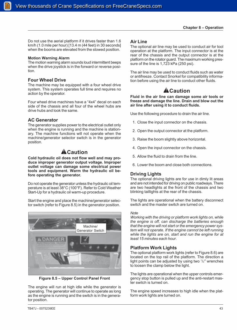
Chapter 8 – Operation
TB47J – 0075239EE 43
Air LineThe optional air line may be used to conduct air for tooloperation at the platform. The input connector is at therear of the chassis and the output connector is at theplatform on the rotator guard. The maximum working pres-sure of the line is 1,723 kPa (250 psi).
The air line may be used to conduct fluids such as wateror antifreeze. Contact Snorkel for compatibility informa-tion before using the air line to conduct other fluids.
ACautionFluid in the air line can damage some air tools orfreeze and damage the line. Drain and blow out theair line after using it to conduct fluids.
Use the following procedure to drain the air line.
1. Close the input connector on the chassis.
2. Open the output connector at the platform.
3. Raise the boom slightly above horizontal.
4. Open the input connector on the chassis.
5. Allow the fluid to drain from the line.
6. Lower the boom and close both connections.
Driving LightsThe optional driving lights are for use in dimly lit areasand are not intended for driving on public roadways. Thereare two headlights at the front of the chassis and twoblinking taillights at the rear of the chassis.
The lights are operational when the battery disconnectswitch and the master switch are turned on.
NoteWorking with the driving or platform work lights on, whilethe engine is off, can discharge the batteries enoughthat the engine will not start or the emergency power sys-tem will not operate. If the engine cannot be left runningwhile the lights are on, start and run the engine for atleast 15 minutes each hour.
Platform Work LightsThe optional platform work lights (refer to Figure 8.6) arelocated on the top rail of the platform. The direction alight points can be adjusted by using two 1/2″ wrenchesto loosen the clamp below the light.
The lights are operational when the upper controls emer-gency stop button is pulled up and the anti-restart mas-ter switch is turned on.
The engine speed increases to high idle when the plat-form work lights are turned on.
Do not use the aerial platform if it drives faster than 1.6km/h (1.0 mile per hour) [13.4 m (44 feet) in 30 seconds]when the booms are elevated from the stowed position.
Motion Warning AlarmThe motion warning alarm sounds loud intermittent beepswhen the drive joystick is in the forward or reverse posi-tion.
Four Wheel DriveThe machine may be equipped with a four wheel drivesystem. This system operates full time and requires noaction by the operator.
Four wheel drive machines have a “4x4” decal on eachside of the chassis and all four of the wheel hubs aredrive hubs and look the same.
AC GeneratorThe generator supplies power to the electrical outlet onlywhen the engine is running and the machine is station-ary. The machine functions will not operate when themachine/generator selector switch is in the generatorposition.
ACautionCold hydraulic oil does not flow well and may pro-duce improper generator output voltage. Improperoutlet voltage can damage some electrical powertools and equipment. Warm the hydraulic oil be-fore operating the generator.
Do not operate the generator unless the hydraulic oil tem-perature is at least 38°C (100°F). Refer to Cold WeatherStart-Up for a hydraulic oil warm-up procedure.
Start the engine and place the machine/generator selec-tor switch (refer to Figure 8.5) in the generator position.
Figure 8.5 – Upper Control Panel Front
The engine will run at high idle while the generator isoperating. The generator will continue to operate as longas the engine is running and the switch is in the genera-tor position.
Machine/Generator Switch
View thousands of Crane Specifications on FreeCraneSpecs.comView thousands of Crane Specifications on FreeCraneSpecs.com

Chapter 8 – Operation
44 TB47J – 0075239EE
Figure 8.6 – Platform Work Lights
View thousands of Crane Specifications on FreeCraneSpecs.comView thousands of Crane Specifications on FreeCraneSpecs.com

TB47J – 0075239EE 45
Chapter 9 – Stowing and Transporting
To prevent unauthorized use and damage, properly stowthe aerial platform at the end of each work day. It mustalso be properly stowed while transporting.
StowingThe properly stowed position is shown in Figure 9.1.
Figure 9.1 – Stowed Position
Use the following procedure to properly stow the aerialplatform.
1. Rotate the platform so it is perpendicular to the endof the boom.
2. Fully retract the booms and then lower the main boomuntil the foot on the jib is near the ground to allow forexiting the platform.
3. Center the booms between the rear wheels.
4. If the engine has just been under load and is hot, setthe throttle switch to low and let the engine idle forfive minutes.
5. Turn the start switch off and place the platform con-trol box cover over the upper controls if the machineis equipped with that option.
6. Push the lower controls emergency stop button in-ward. Turn the control selector switch off and removethe key.
7. Turn the battery disconnect switch off.
8. Close and latch the cowling doors.
Tucked StowThe platform may be tucked underneath the main boomto reduce the overall length of the machine when it isstowed for an extended period of time or for transporting.
The tucked stow position is shown in Figure 9.2.
Figure 9.2 – Tucked Stowed Position
Use the following procedure to stow the platform in thetucked position using the lower controls.
1. Rotate the platform so it is perpendicular to the endof the boom.
2. Fully retract the tip boom and then raise the mainboom slightly above horizontal.
3. Operate the platform level switch in the down posi-tion to tuck the platform beneath the main boom.Watch the position of the platform to make sure itdoes not contact the ground surface. It may be nec-essary to slightly raise the main boom to prevent theplatform from contacting the ground
4. Center the booms between the rear wheels.
5. If the engine has just been under load and is hot, setthe throttle switch to low and let the engine idle forfive minutes.
6. Turn the start switch off and place the platform con-trol box cover over the upper controls if the machineis equipped with that option.
7. Push the lower controls emergency stop button in-ward. Turn the control selector switch off and removethe key.
8. Turn the battery disconnect switch off.
9. Close and latch the cowling doors.
TransportingThe aerial platform may be moved on a transport vehicle.Depending on the particular situation, the aerial platformmay be driven, winched, or hoisted onto a vehicle suchas a truck or trailer. Driving is the preferred method.
View thousands of Crane Specifications on FreeCraneSpecs.comView thousands of Crane Specifications on FreeCraneSpecs.com

Chapter 9 – Stowing and Transporting
46 TB47J – 0075239EE
ADangerThe aerial platform can tip over if it becomes un-stable. Death or serious injury will result from a tip-over accident. Do not drive on ramps that exceed25 percent grade, or where conditions of the rampcould cause driving to be hazardous.
Drive the aerial platform onto the transport vehicle if theramp incline is within the 25 percent grade capability ofthe aerial platform.
A 25 percent grade is a 0.76 m (30″) vertical rise in 3.05m (10′) horizontal length.
Use a winch to load and unload the aerial platform onramps that exceed 25 percent grade. A winch may alsobe used when conditions of the ramp could cause drivingto be hazardous.
The equipment used to load, unload, and transport theaerial platform must have adequate capacity. Refer toChapter 2 to determine the approximate weight of theaerial platform.
The user assumes all responsibility for choosing the propermethod of transportation, and the proper selection anduse of transportation and tie-down devices, making surethe equipment used is capable of supporting the weightof the aerial platform and that all manufacturer’s instruc-tions and warnings, regulations and safety rules of theiremployer, the DOT and/or any other state or federal laware followed.
DrivingUse the following procedure to drive the aerial platformonto the transport vehicle.
1. Locate the transport vehicle so it is in a straight linewith the loading ramp.
2. Chock the vehicle wheels so it cannot roll away fromthe ramp while the machine is loaded.
3. Remove any unnecessary tools, materials, or otherloose objects from the platform.
4. Drive the machine to the foot of the loading ramp withthe front wheels nearest the ramp. Make sure themachine is centered with the ramps and that the steer-ing wheels are straight.
5. Rotate the platform so it is perpendicular to the boom.
6. Retract the tip boom and raise the main boom so itis horizontal.
7. Rotate the turntable slightly to the side so you cansee the front wheels.
8. Verify that the machine wheels, loading ramps, andtransport vehicle are aligned.
ADangerThe aerial platform can tip over if it becomes un-stable. Death or serious injury will result from a tip-over accident. Set the drive range to low beforedriving up or down a grade.
9. Place the drive range switch in the low position.
10. Drive the aerial platform onto the transport vehicle ina straight line through the grade transitions with mini-mal turning.
11. Rotate the turntable to align the main boom betweenthe rear wheels.
12. When driving down the ramp, always back the ma-chine with the platform on the downhill side only.
WinchingUse the following procedure to winch the aerial platformonto the transport vehicle.
1. Locate the transport vehicle so the aerial platformwill not roll forward after it is loaded.
2. Remove any unnecessary tools, materials, or otherloose objects from the platform.
3. Drive the machine to the foot of the loading ramp withthe front wheels nearest the ramp. Make sure themachine is centered with the ramps and that the steer-ing wheels are straight.
4. Properly stow the aerial platform.
5. Attach the winch to the tie-down lugs (refer to Figure9.3) on the front of the chassis.
Figure 9.3 – Front Tie-Down Lugs
6. At each drive wheel, remove the two bolts from thedisconnect plate (refer to Figure 9.4). Turn the plateover so the nipple points inward. Reinstall the twobolts.
Tie-DownLugs
View thousands of Crane Specifications on FreeCraneSpecs.comView thousands of Crane Specifications on FreeCraneSpecs.com
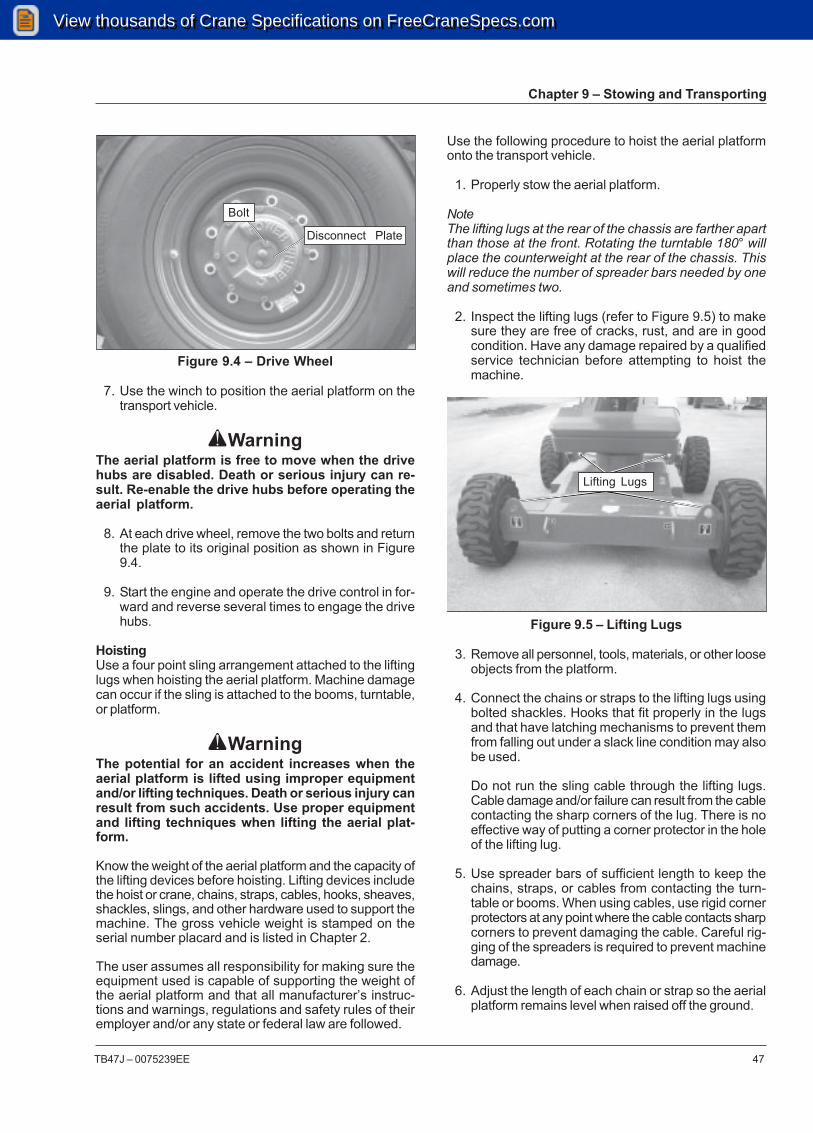
Chapter 9 – Stowing and Transporting
TB47J – 0075239EE 47
Figure 9.4 – Drive Wheel
7. Use the winch to position the aerial platform on thetransport vehicle.
AWarningThe aerial platform is free to move when the drivehubs are disabled. Death or serious injury can re-sult. Re-enable the drive hubs before operating theaerial platform.
8. At each drive wheel, remove the two bolts and returnthe plate to its original position as shown in Figure9.4.
9. Start the engine and operate the drive control in for-ward and reverse several times to engage the drivehubs.
HoistingUse a four point sling arrangement attached to the liftinglugs when hoisting the aerial platform. Machine damagecan occur if the sling is attached to the booms, turntable,or platform.
AWarningThe potential for an accident increases when theaerial platform is lifted using improper equipmentand/or lifting techniques. Death or serious injury canresult from such accidents. Use proper equipmentand lifting techniques when lifting the aerial plat-form.
Know the weight of the aerial platform and the capacity ofthe lifting devices before hoisting. Lifting devices includethe hoist or crane, chains, straps, cables, hooks, sheaves,shackles, slings, and other hardware used to support themachine. The gross vehicle weight is stamped on theserial number placard and is listed in Chapter 2.
The user assumes all responsibility for making sure theequipment used is capable of supporting the weight ofthe aerial platform and that all manufacturer’s instruc-tions and warnings, regulations and safety rules of theiremployer and/or any state or federal law are followed.
Use the following procedure to hoist the aerial platformonto the transport vehicle.
1. Properly stow the aerial platform.
NoteThe lifting lugs at the rear of the chassis are farther apartthan those at the front. Rotating the turntable 180° willplace the counterweight at the rear of the chassis. Thiswill reduce the number of spreader bars needed by oneand sometimes two.
2. Inspect the lifting lugs (refer to Figure 9.5) to makesure they are free of cracks, rust, and are in goodcondition. Have any damage repaired by a qualifiedservice technician before attempting to hoist themachine.
Figure 9.5 – Lifting Lugs
3. Remove all personnel, tools, materials, or other looseobjects from the platform.
4. Connect the chains or straps to the lifting lugs usingbolted shackles. Hooks that fit properly in the lugsand that have latching mechanisms to prevent themfrom falling out under a slack line condition may alsobe used.
Do not run the sling cable through the lifting lugs.Cable damage and/or failure can result from the cablecontacting the sharp corners of the lug. There is noeffective way of putting a corner protector in the holeof the lifting lug.
5. Use spreader bars of sufficient length to keep thechains, straps, or cables from contacting the turn-table or booms. When using cables, use rigid cornerprotectors at any point where the cable contacts sharpcorners to prevent damaging the cable. Careful rig-ging of the spreaders is required to prevent machinedamage.
6. Adjust the length of each chain or strap so the aerialplatform remains level when raised off the ground.
Lifting Lugs
Bolt
Disconnect Plate
View thousands of Crane Specifications on FreeCraneSpecs.comView thousands of Crane Specifications on FreeCraneSpecs.com

Chapter 9 – Stowing and Transporting
48 TB47J – 0075239EE
7. Use the hoist or crane to carefully raise and positionthe aerial platform onto the transport vehicle.
Securing for TransportUse the following procedure to secure the aerial platformon the transport vehicle.
1. Chock the wheels.
2. Raise the main boom about 0.3 m (1′).
3. Place a wood block under the jib foot. Lower the plat-form so the foot rests on the wood block.
4. Remove all personnel, tools, materials, or other looseobjects from the platform.
5. Turn the start switch off and place the platform con-trol box cover over the upper controls if the machineis equipped with that option.
6. Push the lower controls emergency stop button in-ward. Turn the control selector switch off and removethe key.
7. Turn the battery disconnect switch off.
8. Close and latch the cowling doors.
9. Use wire-ties to fasten the platform gate to the guard-rails to prevent the gate from bouncing. Also, usewire-ties to fasten the platform foot switch to the plat-form floor.
10. Use a nylon strap to securely fasten the platformagainst the wood block. Thread the strap over thetoeboard as shown in Figure 9.6.
Figure 9.6 – Platform
ACautionRatchets, winches, and come-alongs can produceenough force to damage machine components. Donot over tighten the straps or chains when securingthe aerial platform to the transport vehicle.
11. Use chains or straps to securely fasten the aerialplatform to the transport vehicle using the tie-downlugs as attachment points. Proper tie-down and haul-ing are the responsibility of the carrier.
View thousands of Crane Specifications on FreeCraneSpecs.comView thousands of Crane Specifications on FreeCraneSpecs.com

TB47J – 0075239EE 49
Figure 10.2 – Lower Controls
5. Hold the appropriate function toggle switch in thedesired direction.
Upper ControlsFor the upper controls to be operational:
• the battery disconnect switch must be in the on po-sition.
• the emergency stop button at the lower controls mustbe in the on position.
• the controls selector switch at the lower controls mustbe in the upper controls position.
Use the following procedure to operate the machine us-ing the emergency power system from the upper con-trols.
1. Pull the emergency stop button outward (refer to Fig-ure 10.3).
2. Turn the start switch on.
3. Place the drive/boom selector switch in the appropri-ate position.
4. Step down on the platform foot switch (refer to Figure10.4).
Chapter 10 – Emergency Operation
If the main hydraulic system fails, the aerial platform maybe lowered and stowed using the emergency power sys-tem. The main boom may be lowered using the emer-gency lowering knob. The machine may be towed if thedrive system fails. Refer to Emergency Power System,Emergency Lowering, or Towing for the appropriate pro-cedure.
Emergency Power SystemThe emergency power system can be used to operatethe machine from the lower or upper controls.
ACautionThe emergency power system is for emergency low-ering and stowing only. The length of time the pumpcan be operated depends on the capacity of thebattery. Do not use this system for normal opera-tion.
Only use the emergency power system if the main powersystem fails.
Lower ControlsUse the following procedure to operate the machine us-ing the emergency power system from the lower con-trols.
1. Place the battery disconnect switch in the on posi-tion (refer to Figure 10.1).
Figure 10.1 – Battery Disconnect Switch
2. Place the key in the control selector switch (refer toFigure 10.2) and turn the control switch to the lowercontrol position.
3. Pull the emergency stop button outward.
4. Hold the ground operation switch in the on positionwhile holding the engine/emergency power switchdown in the emergency power position.
Battery Disconnect Switch
Ground OperationSwitch
EmergencyStop Button
Control SelectorSwitch
Engine/EmergencyPower Switch
Start Switch
View thousands of Crane Specifications on FreeCraneSpecs.comView thousands of Crane Specifications on FreeCraneSpecs.com

Chapter 10 – Emergency Operation
50 TB47J – 0075239EE
Figure 10.4 – Platform Foot Switch
5. Hold the engine/emergency power switch in the emer-gency power position.
6. Hold the appropriate function toggle switch in thedesired direction.
Emergency LoweringThe main boom can be lowered in an emergency usingthe emergency lowering knob at the base of the lift cylin-der. The emergency lowering knob allows the main boomto be lowered only. Only use this method if the enginewill not start and the emergency power system will notwork.
ADangerPinch points exist between boom components andbetween the booms and turntable. Death or seriousinjury will result if the booms or platform lowersonto personnel. Make sure all personnel stand clearwhile lowering the booms.
Use the following procedure to manually lower the mainboom.
1. Slowly turn the knob (refer to Figure 10.5) to openthe bleed down valve. Control the rate of descent byturning the knob.
Figure 10.5 – Emergency Lowering Knob
AWarningThe potential for an accident increases when safetydevices do not function properly. Death or seriousinjury can result from such accidents. Fully closethe emergency lowering knob before operating theaerial platform.
2. Turn the knob to close the cylinder bleed down valve.
TowingThe aerial platform may be towed at slow speeds usingthe optional tow kit. The tow vehicle must have sufficientcapacity to safely tow and stop itself and the aerial plat-form on the steepest grade and type of surface that maybe encountered. Refer to Chapter 2 for the gross vehicleweight of the aerial platform.
EmergencyLowering Knob
Figure 10.3 – Upper Controls
Platform FootSwitch
Top Front
Start Switch
Emergency Stop Engine/EmergencyPower Switch
Drive/BoomSelector
View thousands of Crane Specifications on FreeCraneSpecs.comView thousands of Crane Specifications on FreeCraneSpecs.com

Chapter 10 – Emergency Operation
TB47J – 0075239EE 51
Figure 10.6 – Drive Wheel
8. Pull the steering float valve knob out. The knob islocated behind the rear door on the right side of theturntable next to the fuel tank.
9. Do not exceed 16 km/h (10 mph) when towing. Usecaution when traveling around a curve or when turn-ing a corner. If the tow bar contacts the chassis thesteering mechanism might be damaged or the towvehicle and the aerial platform could jackknife.
AWarningThe aerial platform is free to move when the drivehubs are disabled. Death or serious injury can re-sult. Re-enable the drive hubs before operating theaerial platform.
10. Push the steering float valve knob in.
11. At each drive wheel, remove the two bolts and returnthe plate to its original position as shown in Figure10.6.
12. Unfasten the tow vehicle from the machine and re-place the tow bar on the storage cradles.
13. Verify that the drive system operates properly.
AWarningThe aerial platform is free to move when the drivehubs are disabled. Death or serious injury can re-sult. Securely fasten the tow vehicle to the aerialplatform before disabling the drive hubs.
Use the following procedure to manually disengage thedrive hubs and tow the machine.
1. With the machine in the stowed position, remove thetow bar from the storage cradles at the rear of thechassis and lay the tow bar near the front of the chas-sis.
ADangerPinch points may exist between machine compo-nents. Death or serious injury will result from be-coming trapped between components. Do not at-tach the tow bar to the tow vehicle until the coun-terweight is to the side of the chassis.
2. Rotate the turntable, until the counterweight is to theside of the chassis, to allow room to attach the towbar.
3. Attach the tow bar to the front steering arm with thetow pin and snap pin.
4. Attach the tow bar to the tow vehicle.
5. Rotate the turntable so the counterweight is back atthe front of the chassis. Raise the platform about 1 m(3′) above the ground.
6. Shut the engine off and turn the battery disconnectswitch off.
7. At each drive wheel, remove the two bolts from thedisconnect plate (refer to Figure 10.6). Turn the plateover so the nipple points inward. Reinstall the twobolts.
Bolt
Disconnect Plate
View thousands of Crane Specifications on FreeCraneSpecs.comView thousands of Crane Specifications on FreeCraneSpecs.com

Chapter 10 – Emergency Operation
52 TB47J – 0075239EE
View thousands of Crane Specifications on FreeCraneSpecs.comView thousands of Crane Specifications on FreeCraneSpecs.com

TB47J – 0075239EE 53
Chapter 11 – Troubleshooting
The troubleshooting chart may be used to locate andeliminate situations where machine operation may beinterrupted. If the problem cannot be corrected with the
action listed, stow the machine and remove it from ser-vice. Repairs must be made by qualified maintenancepersonnel.
Troubleshooting Chart
Symptom
Engine will not start from lower orupper controls.
Engine will not start from lowercontrols.
Possible Cause
Out of fuel. The engine will crank,but will not start.
Engine is cold.
High engine temperature.
Low oil pressure.
Switches are set wrong. The enginewill not crank.
The control selector switch was leftin the lower control position for 30seconds or longer before starting theengine.
The main system circuit breaker onthe wiring box has tripped. The en-gine will not crank.
Corrective Action
Add correct type of fuel. Try startingthe engine for 20 seconds and thenlet the starter motor cool for 60 sec-onds. Repeat as necessary.
Cummins engine – plug the blockheater in eight hours before startingthe engine.
Deutz engine – hold the manifoldheater switch on for about a minutebefore starting the engine. Hold theswitch on until the engine starts.
Let engine cool. Do not restart theengine until the cause of overheat-ing has been corrected.
Do not try to start the engine untilthe cause of low oil pressure hasbeen corrected. The engine can berestarted with low oil pressure, butit will only run a few seconds beforeit shuts off again.
Turn the battery disconnect switchon and then at the lower controls:
• Turn the control selector switchoff.
• Pull the emergency stop buttonoutward.
• Place the control selectorswitch in the lower control posi-tion.
• Wait for 5 seconds and thenpress the start switch to start.
Press the start button within 30 sec-onds of placing the control selectorin the lower controls position.
Push the main system circuit breakerbutton back in. If the button popsback out, refer the problem to aqualified service technician.
View thousands of Crane Specifications on FreeCraneSpecs.comView thousands of Crane Specifications on FreeCraneSpecs.com

Chapter 11 – Troubleshooting
54 TB47J – 0075239EE
Symptom
Engine will not start from uppercontrols.
Engine dies when the control se-lector switch at the lower controlsis placed in the platform position.
Constant tone alarm sounds whilethe engine is running.
Possible Cause
Switches are set wrong. The enginewill not crank.
Platform foot switch is activated.
The start switch was left in the onposition for 30 seconds or longer be-fore turning it to start.
The main system circuit breaker onthe upper control panel or wiring boxhas tripped. The engine will not crank.
Upper controls are not set-up prop-erly.
High engine temperature.
Low oil pressure.
No alternator current/broken fan belt.
Corrective Action
Turn the battery disconnect switch onand then at the lower controls:
• Turn the control selector switchoff.
• Pull the emergency stop buttonoutward.
• Place the control selector switchin the upper control position.
From the upper controls:
• Turn the start switch off.
• Pull the emergency stop buttonoutward.
• Place the start switch in the onposition for 5 seconds and thethen turn the switch to start.
Do not step on foot switch while start-ing the engine.
Turn the start switch back to off, thento start within 30 seconds.
Push the main system circuit breakerbutton back in. If the button pops backout, refer the problem to a qualifiedservice technician.
At the upper controls, pull the emer-gency stop button upward and turnthe anti-restart master switch on.
Lower the platform and reduce theengine speed to idle for five minutes.Turn the engine off and let it cool. Donot restart the engine until the causeof overheating has been corrected.
Lower the platform and turn the en-gine off. Do not restart the engine untilthe cause of low oil pressure has beencorrected.
Turn the engine off. Do not restart theengine until the cause of no alterna-tor current has been corrected or thefan belt is replaced.
View thousands of Crane Specifications on FreeCraneSpecs.comView thousands of Crane Specifications on FreeCraneSpecs.com

Chapter 11 – Troubleshooting
TB47J – 0075239EE 55
Symptom
Constant tone alarm sounds andengine shuts off.
Horn is sounding intermittentlyand the overload light is flashing.
Horn is sounding constantly andthe overload light is on.
Platform overload sense systemdoes not work while operating theupper controls.
Boom functions do not immedi-ately return when switching fromdrive to boom. There is a delay inboom functions after switching thedrive/boom switch to the boomposition after driving the machinewith the boom below horizontal.
All functions stop working.
Lower controls donot work.
Possible Cause
High engine temperature.
Low oil pressure.
The load in the platform is greaterthan the rated capacity.
The platform overload system has anerror.
Drive/boom selector switch is in thedrive position and the main boom isbelow horizontal.
System needs calibration.
Platform overload system delay.
Low fluid level in reservoir.
Engine or pump failure.
Circuit breaker is tripped.
Electrical system malfunction.
Platform overload sensor is tripped.
Battery disconnect switch turned off.
Emergency stop switch at lower con-trols is pushed in to the off position.
Corrective Action
Let the engine cool. Do not restartthe engine until the cause of overheat-ing has been corrected.
Do not restart the engine until thecause of low oil pressure has beencorrected. The engine can be re-started with low oil pressure, but itwill only run a few seconds before itshuts off again.
Remove load from the platform untilthe alarms stop.
Remove load until at or below ratedcapacity. Cycle machine power off,then on. If alarm continues, systemmay need recalibration.
Normal operation. The platform over-load system is inactive while drivingwith the boom below horizontal toprevent accidental activation due torough terrain.
Refer the problem to a qualified ser-vice technician.
Normal operation. The system in-cludes a 5 second delay to eliminaterapid stop and restart of movementsif the overload system trips duringoperation.
Check fluid level. Add correct type offluid if necessary.
Manually stow the machine using theemergency power system or theemergency lowering knob.
Push circuit breaker button in to re-set.
Manually lower the boom using theemergency lowering knob.
If horn is sounding and red overloadlight is on or blinking, remove weightfrom the platform until the load is ator below rated capacity.
Place switch in the on position.
Pull the emergency stop button outto the on position.
View thousands of Crane Specifications on FreeCraneSpecs.comView thousands of Crane Specifications on FreeCraneSpecs.com

Chapter 11 – Troubleshooting
56 TB47J – 0075239EE
Symptom
Lower controls do not work.
Upper controls do not work.
Boom functions do not work.
Boom and drive functions seemsluggish.
Boom jerks while it is extended.
Tip boom extend/retract, jib, andplatform rotate functions do notwork from the upper controls.
Booms drift down.
Possible Cause
Control selector switch is in the plat-form position.
Ground operation switch not held inthe on position.
Platform overload sensor is tripped.
Battery disconnect switch turned off.
Emergency stop switch at lower andupper controls is in the off position.
Control selector switch at lower con-trols is in the lower control position.
Platform foot switch not engaged.
Platform overload sensor is tripped.
The drive/boom switch is in the driveposition.
Hydraulic oil is cold and thick.
Wire ropes are loose.
Boom speed knob set too slow.
The emergency lowering valve is open.
Hydraulic system malfunction.
Corrective Action
Place the switch in the lower controlposition.
Hold the ground operation switch inthe on position while operating thecontrol toggle switches.
If horn is sounding and red overloadlight is on or blinking, remove weightfrom the platform until the load is ator below rated capacity.
Place switch in the on position.
Place the emergency stop in the onposition.
Place switch in the upper control po-sition.
Step down on platform foot switchwhile operating controls.
If horn is sounding and red overloadlight is on or blinking, remove weightfrom the platform until the load is ator below rated capacity.
Place the switch in the boom posi-tion.
Use cold weather hydraulic oil as rec-ommended for weather conditions.Warm oil before operating the ma-chine.
Refer the problem to a qualified ser-vice technician.
Turn knob toward fast.
Turn the emergency lowering knob toclose the valve.
Stow the machine and do not oper-ate until repairs are made.
View thousands of Crane Specifications on FreeCraneSpecs.comView thousands of Crane Specifications on FreeCraneSpecs.com

Chapter 11 – Troubleshooting
TB47J – 0075239EE 57
Symptom
Drive functions donot work.
Wheels will not turn whenwinching.
Only slow drive speed works.
Steer wheels do not turn right orleft on machines with tow option.
Tilt alarm does not work.
Circuit breaker will not reset.
Electrical outlet does not work.
Improper AC generator outputvoltage.
Hydraulic fluid temperature 93°C(200°F ) or more.
Severe hydraulic leak.
Possible Cause
The drive/boom switch is in the boomposition.
Machine on too steep a grade.
Drive hubs are disengaged.
Low hydraulic system pressure.
Platform overload sensor is tripped.
Drive hubs are engaged.
The booms are elevated. High rangenot selected.
Tow kit steering float valve is open.
Booms are stowed.
Electrical circuit has not had time tocool.
Electrical system malfunction.
Power supply not plugged in.
Machine/generator switch not in thegenerator position.
Hydraulic oil is cold and thick.
Prolonged boom operation or driving.
High pressure fluid return to reser-voir caused by kinked or twistedhose.
Hydraulic system component failure.
Failure of hose, tube, fitting, seal,etc.
Corrective Action
Place the switch in the drive position.
Lower the booms and drive to a levelsurface.
Turn drive wheel disconnect platesaround so nipples point outward.
Stow the machine and do not oper-ate until repairs are made.
If horn is sounding and red overloadlight is on or blinking, remove weightfrom the platform until the load is ator below rated capacity.
Turn drive wheel disconnect platesaround so nipples point inward.
Completely lower the booms. Placethe drive range switch in the high po-sition.
Close the steering float valve.
Normal operation. The tilt alarm is notactive until the booms are elevated.
Wait a minute or two for circuit tocool, then push circuit breaker but-ton in to reset.
Do not operate machine until repairsare made.
Plug the power cord into the power-input connector on the generator.
With engine running, place the ma-chine/generator switch in the genera-tor position.
Use cold weather hydraulic oil as rec-ommended. Warm oil before operat-ing the machine.
Stop operation until fluid cools.
Remove the kink or twist from thehose. Let fluid cool before resumingoperation.
Stow the machine and do not oper-ate until repairs are made.
Do not operate machine until repairsare made.
View thousands of Crane Specifications on FreeCraneSpecs.comView thousands of Crane Specifications on FreeCraneSpecs.com

Chapter 11 – Troubleshooting
58 TB47J – 0075239EE
View thousands of Crane Specifications on FreeCraneSpecs.comView thousands of Crane Specifications on FreeCraneSpecs.com

TB47J – 0075239EE
Appendix A – Glossary
aerial platform – a mobile device that has an adjustable positionplatform, supported from ground level by a structure.
ambient temperature – the air temperature of the immediate environ-ment.
ammeter – an instrument for measuring the strength of an electriccurrent in amperes.
authorized personnel – personnel approved as assigned to performspecific duties at a specific location.
base – the relevant contact points of the aerial platform that form thestability support (e.g. wheels, casters, outriggers, stabilizers).
boom – a movable cantilever beam which supports the platform.
center of gravity – the point in the aerial platform around which itsweight is evenly balanced.
chassis – the integral part of the aerial platform that provides mobil-ity and support for the booms.
fall restraint – a system that is used while working on a boom lift withinthe boundaries of platform guardrails to provide restraint from beingprojected upward from the platform. This system includes a harness orbelt, lanyard, and a lanyard anchor. Federal OSHA, ANSI, and Snorkelrequire the use of additional fall protection beyond the platform guard-rails on boom supported aerial platforms.
floor or ground pressure – the maximum pressure, expressed in poundsper square inch, a single wheel concentrates on the floor or ground.
gradeability – the maximum slope that the aerial platform is capableof travel.
guardrail system – a vertical barrier around the platform to preventpersonnel from falling.
hazardous location – any location that contains, or has the potentialto contain, an explosive or flammable atmosphere as defined byANSI/NFPA 505.
intermediate boom – a telescopic boom section that extends andretracts from within the main boom. The intermediate boom is be-tween the base, or lower most section of the main boom, and the tipboom.
jib – an articulating boom attached to the tip boom which increasesthe overall boom reach.
level sensor – a device that detects a preset degree of variation fromperfect level. The level sensor is used to sound an alarm if operatingon a slope greater than the preset value.
lower controls – the controls located at ground level for operatingsome or all of the functions of the aerial platform.
main boom – a boom assembly located between the turntable and theplatform.
manufacturer – a person or entity who makes, builds or produces anaerial platform.
maximum travel height – the maximum platform height or the mostadverse configuration(s) with respect to stability in which travel is per-mitted by the manufacturer.
maximum wheel load – the load or weight that can be transmittedthrough a single wheel to the floor or ground.
Minimum Safe Approach Distance – the minimum safe distance thatelectrical conductors may be approached when using the aerial plat-form. Also called M.S.A.D.
operation – the performance of any aerial platform functions withinthe scope of its specifications and in accordance with the manufacturer’sinstructions, the users work rules, and all applicable governmentalregulations.
operator – a qualified person who controls the movement of an aerialplatform.
personal fall arrest system – a fall protection system that is usedwhile working on an unprotected edge (such as a roof top with noguardrail). This system includes a harness, lanyard or other connectingdevice, a fall arrestor, an energy absorber or decelerator, an anchor-age connector, and a secure anchorage such as a building beam,girders or columns. An aerial platform is not a fall arrest anchorage.
platform – the portion of an aerial platform intended to be occupiedby personnel with their tools and materials.
platform height – the vertical distance measured from the floor of theplatform to the surface upon which the chassis is being supported.
prestart inspection – a required safety inspection routine that isperformed daily before operating the aerial platform.
qualified person – a person, who by reason of knowledge, experience,or training is familiar with the operation to be performed and thehazards involved.
rated work load – the designed carrying capacity of the aerial plat-form as specified by the manufacturer.
stow – to place a component, such as the platform, in its rest position.
tip boom – a telescopic boom section that extends and retracts fromwithin the main boom. The tip boom is nearest the platform.
turning radius – the radius of the circle created by the wheel during a360° turn with the steering wheels turned to maximum. Inside turningradius is the wheel closest to the center and outside turning radius isthe wheel farthest from the center.
turntable – the structure above the rotation bearing which supports themain boom. The turntable rotates about the centerline of rotation.
unrestricted rated work load – the maximum designed carrying ca-pacity of the aerial platform allowed by the manufacturer in all oper-ating configurations.
upper controls – the controls located on or beside the platform usedfor operating some or all of the functions of the aerial platform.
wheelbase – the distance from the center of the rear wheel to thecenter of the front wheel.
working envelope – the area defined by the horizontal and verticallimits of boom travel that the platform may be positioned in.
working height – platform height plus six feet.
View thousands of Crane Specifications on FreeCraneSpecs.comView thousands of Crane Specifications on FreeCraneSpecs.com

Appendix A – Glossary
TB47J – 0075239EE
View thousands of Crane Specifications on FreeCraneSpecs.comView thousands of Crane Specifications on FreeCraneSpecs.com

© Snorkel International, Inc. – all rights reserved Printed in the U.S.A.
LIMITED WARRANTYSnorkel warrants each new machine manufactured and sold by it to be free from defects in material and workmanship for aperiod of one (1) year from date of delivery to a Customer or for one year after the machine has been placed in first service ina Dealer rental fleet, whichever comes first. Any part or parts which, upon examination by the Snorkel Service Department, arefound to be defective, will be replaced or repaired, at the sole discretion of Snorkel, through its local Authorized Dealer at nocharge.
Snorkel further warrants the structural components; specifically, the mainframe chassis, turntable, booms and scissor arms, ofeach new machine manufactured by it to be free from defects in material and workmanship for an additional period of four (4)years. Any such part or parts which, upon examination by the Snorkel Service Department, are found to be defective will bereplaced or repaired by Snorkel through its local Authorized Dealer at no charge; however, any labor charges incurred as a resultof such replacement or repair will be the responsibility of the Customer or Dealer.
The Snorkel Service Department must be notified within forty-eight (48) hours of any possible warranty situation during theapplicable warranty period. Personnel performing warranty repair or replacement must obtain specific approval by SnorkelService Department prior to performing any warranty repair or replacement.
Customer and Dealer shall not be entitled to the benefits of this warranty and Snorkel shall have no obligations hereunder unlessthe “Pre-Delivery and Inspection Report” has been properly completed and returned to the Snorkel Service Department within ten(10) days after delivery of the Snorkel product to Customer or Dealer’s rental fleet. Snorkel must be notified, in writing, within ten(10) days, of any machine sold to a Customer from a Dealer’s rental fleet during the warranty period.
At the direction of the Snorkel Service Department, any component part(s) of Snorkel products to be replaced or repaired underthis warranty program must be returned freight prepaid to the Snorkel Service Department for inspection. All warranty replace-ment parts will be shipped freight prepaid (standard ground) from the Snorkel Service Department or from Snorkel’s Vendor toDealer or Customer.
REPLACEMENT PARTS WARRANTY
Any replacement or service part made or sold by Snorkel is not subject to the preceding Limited Warranty beyond the normalwarranty period of the machine upon which the part was installed.
THIS WARRANTY EXCLUDES AND SNORKEL DOES NOT WARRANT: 1. Engines, motors, tires and batteries which are manufactured by suppliers to Snorkel, who furnish their own warranty.
Snorkel will, however, to the extent permitted, pass through any such warranty protection to the Customer or Dealer.
2. Any Snorkel product which has been modified or altered outside Snorkel’s factory without Snorkel’s written approval, ifsuch modification or alteration, in the sole judgment of Snorkel’s Engineering and/or Service Departments, adversely affectsthe stability, reliability or service life of the Snorkel product or any component thereof.
3. Any Snorkel product which has been subject to misuse, improper maintenance or accident. “Misuse” includes but is notlimited to operation beyond the factory-rated load capacity and speeds. “Improper maintenance” includes but is not limitedto failure to follow the recommendations contained in the Snorkel Operation, Maintenance, Repair Parts Manuals. Snorkel isnot responsible for normal maintenance, service adjustments and replacements, including but not limited to hydraulic fluid,filters and lubrication.
4. Normal wear of any Snorkel component part(s). Normal wear of component parts may vary with the type application or typeof environment in which the machine may be used; such as, but not limited to sandblasting applications.
5. Any Snorkel product that has come in direct contact with any chemical or abrasive material.
6. Incidental or consequential expenses, losses, or damages related to any part or equipment failure, including but not limitedto freight cost to transport the machine to a repair facility, downtime of the machine, lost time for workers, lost orders, lostrental revenue, lost profits or increased cost.
This warranty is expressly in lieu of all other warranties, representations or liabilities of Snorkel, either expressed or implied,unless otherwise amended in writing by Snorkel’s President, Vice President-Engineering, Vice President-Sales or Vice Presi-dent-Marketing.
SNORKEL MAKES NO WARRANTIES WHICH EXTEND BEYOND THE DESCRIPTION OF THIS LIMITED WARRANTY. SNORKELMAKES NO IMPLIED WARRANTY OF MERCHANTABILITY OR FITNESS FOR A PARTICULAR PURPOSE AND DISCLAIMSALL LIABILITY FOR INCIDENTAL OR CONSEQUENTIAL DAMAGES, INCLUDING BUT NOT LIMITED TO INJURY TO PERSONSOR PROPERTY.
The Customer shall make all warranty claims through its local Authorized Dealer and should contact the Dealer from whom theSnorkel product was purchased for warranty service. Or, if unable to contact the Dealer, contact the Snorkel Service Departmentfor further assistance.Effective July 1995
View thousands of Crane Specifications on FreeCraneSpecs.comView thousands of Crane Specifications on FreeCraneSpecs.com

View thousands of Crane Specifications on FreeCraneSpecs.comView thousands of Crane Specifications on FreeCraneSpecs.com