operating & maintenance manual control system smoke …
TRANSCRIPT

Software version: SVCS2E
* Enclosure design may vary
OPERATING & MAINTENANCE MANUAL
SVCS-2SMOKE VENTCONTROL SYSTEM

2
CONTENTS
General Overview / Operation 3
Function 4
Installation 5
Cabling 6
Operating Elements 7
Programming / Interlinking Panels 13
Programming / Timer Adjustment 14
Connections (i) - Mains, Actuators, Overrides & Switches 8
Connections (ii) - Smoke Sensors, Breakglass & Fire Alarm 9
Connections (iii) - All
Battery Information 12
Testing 15
LED Indicators 17
Maintenance 18
Maintenance Schedule 19
SVCS-2
Type: SVCS2E Version: 1.0
– OPERATING & MAINTENANCE MANUAL
10

3
GENERAL OVERVIEW
The VCS series of smoke vent systems are easy to operate, need very little maintenance and are "intelligent", in that for most common failures (wiring, power supplies etc.) they will set some form of warning alarm.
OPERATION
Once fully installed the system is totally automatic and provided that the Red FAULT LED indicator is not on and there are no warning sounds the system will upon receipt of an alarm input condition (BMS Fire Alarm etc.) open the smoke vents. The smoke vents will stay fully open until the input condition (BMS, Fire Alarm, etc.) has been normalized, when the vents will close. Should you require the vents to stay open after the alarm panel has been silenced (or de-activated) then a manual open command should be issued by use of the manual key switch on the front of the panel.
TECHNICAL SPECIFICATION CA v032 egatloV ylppuSCD v42 egatloV tuptuO
Amp2 tnerruC tuptuO
SVCS-2
Type: SVCS2E Version: 1.0
– OPERATING & MAINTENANCE MANUAL

4
FUNCTION
PANEL KEYSWITCH – PRIORITY 1 OPEN AUTO CLOSE All vents will open even if smoke sensor or break glass call points are not activated.
Will obey any remote inputs. Will close vents even if smoke sensor or break glass call points are activated.
NETWORK COMMANDS – PRIORITY 1 (Network enabled version only) NET OPEN NET AUTO NET CLOSE Vent will open unless a Panel key override Close is operated.
Will obey any remote inputs. Will Close vents even if smoke sensor, break glass, Panel Key Open or call points are activated.
FIREMANS OVERRIDE SWITCH – PRIORITY 1 OPEN AUTO CLOSE Vent will open even if smoke sensor or break glass call points are not activated.
Will obey any remote inputs. Will Close vents even if smoke sensor or break glass call points are activated.
SMOKE SENSOR – 2ND PRIORITY ACTIVATED NOT ACTIVATED All Vents will open unless overridden by FIREMANS OVERRIDE, CONTROL PANEL SWITCH or NETWORK CLOSE.
Vents stay closed.
BREAK GLASS – 2ND PRIORITY ACTIVATED NOT ACTIVATED All Vents will open unless overridden by FIREMANS OVERRIDE, CONTROL PANEL SWITCH or NETWORK COMMANDS.
Vents stay closed.
230V POWER FAILURE PROCEDURE ON POWER FAILURE ACTION RESULT Within 10 minutes Reports a fault. HEALTHY LED goes out and
FAULT LED flashes and panel sounder bleeps every 8 seconds. Net indicates Fault.
After 72 hours Shuts down to minimum power.
The system will function for 180 seconds at full load. After 72 hours and 180 seconds of load the system will continue until batteries are exhausted.
SVCS-2
Type: SVCS2E Version: 1.0
– OPERATING & MAINTENANCE MANUAL
Note: There is no priority between the but a close signal will take priority over signal.
override switchesan open

5
INSTALLATION
1 Please read the contents of this manual in its entirety beforeproceeding with the installation notes below.
2 Unlock cabinet door using key provided and remove PCB.
3 Prepare holes for cable entry. Fit cable glands (by others). Fix cabinet in place.
4 Feed cables into cabinet.
5 Make cable connections as per attached wiring diagrams remove the appropriate connector from the circuit card to facilitate easy access to the connector.
SVCS-2
Type: SVCS2E Version: 1.0
– OPERATING & MAINTENANCE MANUAL
8 Make mains connection, ensuring the cabinet and or thetransformer is earthed (test using low value ohms meter).
6 Connect connector (found on back of enclosure door) board.
Never connect or disconnect any connector whilst the SVCS2 has power applied.
ribbon
7 Connect batteries (supplied with panel) as per the wiringBEFORE mains power is connected.
to control

6
CABLING
Cabling/connection of this panel should only be carried out by a competent person and in accordance with all local and national standards and legislation.
MAINS VOLTAGE Two core + earth on a fused 3 Amp spur or a separate circuit protected by a 6 Amp MCB.
VENT ACTUATORS Two core + earth FP200+ or equivalent for reverse polarity actuators.
Three core + earth FP200+ or equivalent for common with drive open- drive close.
Three core + earth FP200+ or equivalent for Belimo Actuators.
Some actuators have a signal wire to indicate open close status this MUST NOT be connected to the panel.
Cable sizes must be calculated to ensure against excessive voltage drop
Voltage Drop (Vd) should not exceed 2 Volts
The formula is as follows; Vd = mV x A x mWhere;A = total amperage of motorsm = length in metresmV= millivolts per amp per metre figure taken from manufacturers cable data or use the tables in the BS7671 (wiring regs.) document.
Example;1 Supermaster Actuator = 2 Amps max load Cable length m = 20 metres1.5mm square cable == 29mV per amp per metre == 0.029Volts
(0.029 x 2) x 20 = 1.16V (Vd)The above result is well within the limit of a 2 Volt voltage drop.
SVCS-2
Type: SVCS2E Version: 1.0
– OPERATING & MAINTENANCE MANUAL
7
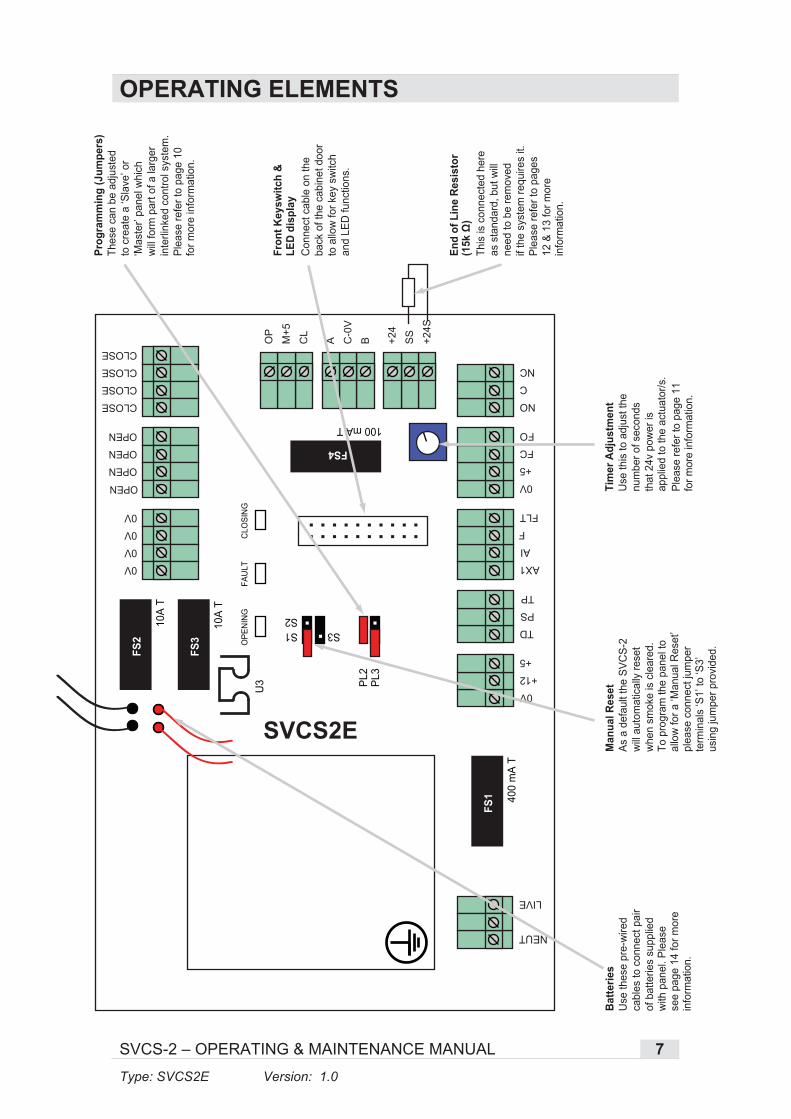
OPERATING ELEMENTS
NEUT
Tim
er A
djus
tmen
tU
se th
is to
adj
ust t
he
num
ber o
f sec
onds
that
24v
pow
er is
ap
plie
d to
the
actu
ator
/s.
Plea
se re
fer t
o pa
ge 1
1fo
r mor
e in
form
atio
n.
Man
ual R
eset
As a
def
ault
the
SVC
S-2
will
auto
mat
ical
ly re
set
whe
n sm
oke
is c
lear
ed.
To p
rogr
am th
e pa
nel t
oal
low
for a
‘Man
ual R
eset
’pl
ease
con
nect
jum
per
term
inal
s ‘S
1’ to
‘S3’
usin
g ju
mpe
r pro
vide
d.
Batte
ries
Use
thes
e pr
e-w
ired
cabl
es to
con
nect
pai
rof
bat
terie
s su
pplie
dw
ith p
anel
. Ple
ase
see
page
14
for m
ore
info
rmat
ion.
Fron
t Key
switc
h &
LED
disp
lay
Con
nect
cab
le o
n th
e ba
ck o
f the
cab
inet
doo
rto
allo
w fo
r key
sw
itch
and
LED
func
tions
.
End
of L
ine
Resi
stor
This
is c
onne
cted
her
eas
sta
ndar
d, b
ut w
ill ne
ed to
be
rem
oved
if
the
syst
em re
quire
s it.
Plea
se re
fer t
o pa
ges
12 &
13
for m
ore
info
rmat
ion.
Thes
e ca
n be
adj
uste
dto
cre
ate
a ‘S
lave
’ or
‘Mas
ter’
pane
l whi
ch
will
form
par
t of a
larg
er
inte
rlink
ed c
ontro
l sys
tem
.Pl
ease
refe
r to
page
10
for m
ore
info
rmat
ion.
LIVE
NO
C
NC
OP
M+5
CL
A C-0
V
B +24
SS
+24S
0V
+5
FC
FO
AX1
AI
F
TD
PS
TP
0V
+12
+5
FLT
CLOSE
CLOSE
CLOSE
CLOSE
OPEN
OPEN
OPEN
OPEN
0V
0V
0V
0V
FS1 40
0 m
A T
FS2
FS3
10A
T
U3
10A
T
100 mA T
FS4
PL2
S3S1S2
PL3
SVCS2E
SVCS-2
Type: SVCS2E Version: 1.0
– OPERATING & MAINTENANCE MANUAL
OPE
NIN
GFA
ULT
CLO
SIN
G

8
CONNECTIONS (i)
0V
+5
FC
FO
FIRE
MAN
S O
VERR
IDE
(RO
CKER
SW
ITCH
)FI
REM
ANS
OVE
RRID
E(K
EY S
WIT
CH)
A2
A3
A1
0V
+5
FC
FO
1
2
7
8
Firemans Override
Firemans Override
SVCS-2 Panel
SVCS-2 Panel
SVCS-2
Type: SVCS2E Version: 1.0
– OPERATING & MAINTENANCE MANUAL
SMO
KE V
ENT
SMO
KE V
ENT
OPEN
OPEN
OPEN
OPEN
CLOSE
BROWN
BLUE
CLOSE
CLOSE
CLOSE
ACTU
ATO
R
Any
of th
e 4
conn
ecto
rsin
eac
h bl
ock
can
be u
sed
Actuator
SVCS-2 Panel
FIRE
ALA
RMN
orm
ally
Ope
n co
ntac
tsC
LOSE
on
fire
+24S
SS
+24
NO
COM
SVCS-2 PanelFire Alarm
NEUTRAL
LIVE
NEUTRALMAI
NS23
0V A
C fr
om
3A F
used
Spu
r
LIVE
SVCS-2 PanelFused Spur
ROCK
ER S
WIT
CH
OP
M+5
CL
L1
COM
L2
SVCS-2 PanelRocker Switch
End
of L
ine
Res
isto
r
As
stan
dard
this
is c
onne
cted
to th
e‘+
24S
’ and
‘SS
’ ter
min
als.
Whe
nco
nnec
ting
a S
mok
e S
enso
r, B
reak
G
lass
and
/or F
ire A
larm
this
resi
stor
mus
t be
rem
oved
and
con
nect
ed (a
ssh
own)
to th
e en
d of
line
.
NC
FP20
0+ 3
C &
EFP
200+
3C
& E
FP20
0+ 3
C &
EFP
200+
2C
& E
FP20
0+ 2
C &
EFP
200+
2C
& E
9
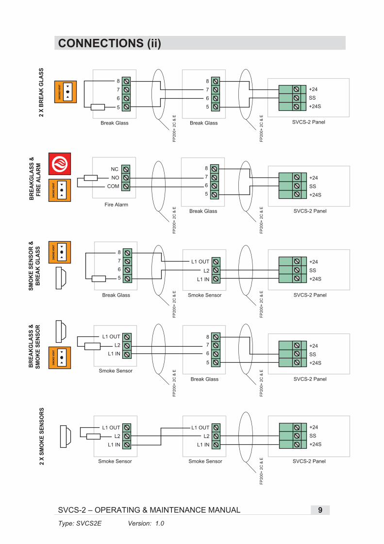
CONNECTIONS (ii)
COM
NO
NC
+24S
SS
+24
SMO
KE S
ENSO
R &
BREA
K G
LASS
L1 IN
Smoke Sensor SVCS-2 Panel
+24S
SS
+24
SVCS-2 Panel
Break Glass
L2
L1 OUT
5
6
7
8
+24S
SS
+24
BREA
KGLA
SS &
SMO
KE S
ENSO
R
L1 IN
Smoke Sensor SVCS-2 PanelBreak Glass
L2
L1 OUT
5
6
78
SVCS-2
Type: SVCS2E Version: 1.0
– OPERATING & MAINTENANCE MANUAL
SMO
KE V
ENT
SMO
KE V
ENT
BREA
KGLA
SS &
FIRE
ALA
RM
Break GlassFire Alarm
5
6
7
8
SMO
KE V
ENT
2 X
BREA
K G
LASS
+24S
SS
+24
5
6
7
8
5
6
7
8
Break GlassBreak Glass SVCS-2 Panel
SMO
KE V
ENT
+24S
SS
+24
2 X
SMO
KE S
ENSO
RS
L1 IN
L2
L1 OUT
L1 IN
L2
L1 OUT
rosneS ekomSrosneS ekomS SVCS-2 Panel
FP20
0+ 2
C &
EFP
200+
2C
& E
FP20
0+ 2
C &
EFP
200+
2C
& E
FP20
0+ 2
C &
E
FP20
0+ 2
C &
EFP
200+
2C
& E
FP20
0+ 2
C &
EFP
200+
2C
& E

CONNECTIONS (iii)
NEU
T
LIV
E
NEU
T
LIV
E
0V AX
1
AX
1 AI F
TD PS
TP0V +12 +5 FLT
0V 0V 0V 0V
FS1
400 mA T
FS2
FS3
10A T
10A T
PL2
S3S1 S2
PL3
SVCS2E
OPENING FAULT CLOSING
BROWN
BLUE
BROWN
BLUE
+ -
- +
Actuator
Actuator
Fire
man
s O
verr
ide
(Sw
itch)
Fuse
d S
pur
SV
CS
-2
Bat
tery
1
Bat
tery
2
SVCS-2
FAULT
INHIBIT
FIRE
HEALTHY
COMM
BATTERYAUTO
CLOSEOPEN
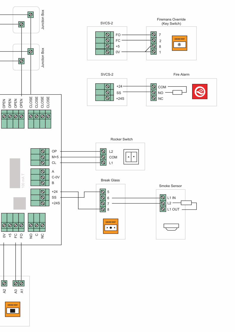
0V
+5
FC
FO
1
2
7
8
SMOKE VENT
Firemans Override(Key Switch)
COM
NO
NC
Fire AlarmSVCS-2
SVCS-2
+24
SS
+24S
A2 A3 A1
NO C
NC
OP
M+5
CL
A
C-0V
B
+24
SS
+24S
0V +5 FC FO
CLO
SE
CLO
SE
CLO
SE
CLO
SE
OPE
N
OPE
N
OPE
N
OPE
N10
0 m
A TFS
4
L2
COML1
SMOKE VENT
Rocker Switch
Junc
tion
Box
Junc
tion
Box
L1 IN
Smoke SensorBreak Glass
L2
L1 OUT
5
6
7
8
SMOKE VENT

12
GENERAL BATTERY SET
Note:
When batteries are changed, the battery charger should be checked for voltage which should read approx. 27.3V, at 20 degrees C. if significantly different please contact technical helpline on number below.
The SVCS-2 has a temperature probe which is to be taped to one of the batteries and located between the batteries, this probe varies the applied charge voltage in accordance with the temperature of the batteries.
There are a number of conditions that can occur in the chemistry of batteries that can give erroneous indications by using simple voltage measurement techniques. The only sure way of testing capacity is with a known load over time and tracking the battery voltage over this time. If the batteries have been abused by discharging them to totally flat and kept in that condition for an extended period it is better to replace them as they are likely to be damaged and therefore may have a much reduced capacity.
This is a guide to the state of charge of the batteries measured Open Circuit, U3 temperature is a guide to whether the batteries are accepting a charge when connected.
VOLTAGE STATE 27.6 Float Charge Voltage
U3 CoolBatteries trickle Charging fully charged
25-27.6 U3 Warm to hot Batteries Charging + 50 – 95% charged
22.1-24.9 U3 Warm to hot Batteries Charging + 10 - 49% charged
21-22 U3 Warm to hot Batteries Charging + <10% charged
14-21.9 May need replacing Batteries Charging + <5% charged
+ gnigrahC seirettaBGNICALPER DEEN LLIW41<<5% charged
BATTERY CONNECTIONS
Temperature Sensor must belocated inbetween batteries (Pre-wired).
TD
PS
TP
0V
+12
+5
Battery 1
Temp. Sensor
Battery 2
SVCS-2 Panel
+
-
-
+
RED (V1)
RED (V2)
BLACK
BLACK
SVCS-2
Type: SVCS2E Version: 1.0
– OPERATING & MAINTENANCE MANUAL

13
PROGRAMMING / INTERLINKING PANELS
MASTER
EXAMPLE SETUP FOR LINKING PANELS
Suitable for:
- Corridor vent- Smoke shaft vent- Lobby vent
Suitable for:
- Stairwell vent- Head of smoke shaft
SLAVE
PL2PL3
PL2PL3
To link panels together a dedicated 2 core and earth cable should be used to connect the AX1 on one panel to the AX1 on the next
next panel. The 0V on one panel should be connected to the 0V on the panel.
The earth cable should be connected through all panels and terminated to earth at one end only, this is to prevent earth loops.This procedure ensures that only one panel may operate at a time in accordance with the “Fire Compartmentation” requirements.
If linking requires a panel to operate as a slave to the others, e.g. a stairwell roof vent, then one adds the spare jumper strap to the OPEN position on the board, should a panel wish to be removed from the interlinking then the BUS strap may be removed or simply disconnect the AX1 Connector. The above cabling/strapping procedure is only required when an RS485 Network is not installed.
Note; The programming jumpers are only to be used when linking panels together. For single zonesystems please use the ‘MASTER’ setup as above.
PL2PL3
PL2PL3
PL2PL3
SVCS-2
Type: SVCS2E Version: 1.0
– OPERATING & MAINTENANCE MANUAL
AX1
AI
F
FLT
AX1
AI
F
FLT
AX1
AI
F
FLT
SVCS-2 Panel (2) SVCS-2 Panel (1) SVCS-2 Panel (3)
Stairwell VentLobby / Corridor Vent Head of Smoke Shaft
SVCS-2
0V
+12
+5
0V
+12
+5
0V
+12
+5

PROGRAMMING / TIMER ADJUSTMENT
90 seconds0 seconds ConstantPower
sdnoces 54(approx) (approx) (approx)
135 seconds
Cycle time can be adjusted between onds or no t t b adjusting the blue potentiometer in the centre of the PCB above the ‘FC’and ‘FO’ terminals this;
Note; The 0 Second position may be used for testing the network without operating roof hatch actuators in inclement weather etc.
If the timer is turned fully clockwise it will send constant power to theactuator/s. We only recommend this program for actuators that require constant power such as Belimo type actuators.
For standard actuators we recommend adjusting this to suit the time it takes the actuator to reach its full opening position (refer to actuator manual for details). Providing constant power to standard actuators can cause the actuator to malfunction and become faulty.
The ‘Opening’ LED on the SVCS-2 will stay lit for as long as there ispower to the actuator/s. If the actuator reaches its full opening positionand the ‘Opening’ LED stays lit for a long period of time we recommend adjusting the timer to a period that is much closer to the time it takes the actuator to reach its full opening position.
5-180 sec imeou y
14SVCS-2
Type: SVCS2E Version: 1.0
– OPERATING & MAINTENANCE MANUAL

15
TESTING
By far the most important thing about the use of this type of equipment is REGULAR TESTING!
Testing has two major functions. A The smoke sensors, alarm panel and vents are fully tested. B Like all mechanical equipment the Vent Actuator motors need to be used
periodically so as to help prevent the build-up of internal corrosion and the likelihood of an associated seizure of the mechanical parts.
Weekly visual (5 minutes) Go to the panel and check for any warning/fault indications. If there is a fault then call your local electrical engineer or call your supplier who will be pleased to help you.
Monthly test (15 minutes) The Full Alarm testing should be carried out with the use of a "Smoke Aerosol". A 5-10 second spray at one of the smoke sensors will set off the alarm system. Each month choose a different smoke sensor. Whilst the alarm is active check that all Vents are open (Note; in accordance with your cause and effect chart), reset the alarm condition (you may have to do this a couple of times if the sensor under test has not cleared the "smoke"). Next check that the manual key-switch will OPEN the Vents (if fitted). After this switch back to AUTO, check again that there no fault conditions and that concludes the test.
Annual Once a year a full battery discharge test is advisable to check the condition of the secondary power supply so that in the event of a fire the firemen have sufficient open and close cycles available for their use. This should be done by a specialist. Call your supplier for further information about annual service contracts.
SVCS-2
Type: SVCS2E Version: 1.0
– OPERATING & MAINTENANCE MANUAL

16
TESTINGThe following are guidance notes around the mandatory maintenance and testing requirements for both powered and natural smoke ventilation systems.
THE REGULATORY REFORM (FIRE SAFETY) ORDER 2005 states
Maintenance 17:- (1) Where necessary in order to safeguard the safety of relevant persons the responsible person must ensure that the premises and any facilities, equipment and devices provided in respect of the premises under this Order or, subject to paragraph (6), under any other enactment, including any enactment repealed or revoked by this Order, are subject to a suitable system of maintenance and are maintained in an efficient state, in efficient working order and in good repair.
BRITISH STANDARD BS 9999:2008 states:
Annex V (normative) Routine inspection and maintenance of fire safety installations
V.1 General NOTE Fire safety installations comprise the items and elements of which examples are listed in Annex J. It is essential for the safety of the occupants of a building that fire safety equipment (including passive fire protection provisions) is inspected frequently. Although much of the inspection can be undertaken by suitably trained personnel, a formal agreement should be made with the installer or the installer’s representative to provide the regular inspection and testing described in the relevant British Standards for individual fire safety installations. Unless temporary alternative fire safety systems can be put in place, it might be appropriate for certain of the inspections carried out at three-monthly or longer intervals to be done outside normal working hours. V.2 Daily inspections V.2.1 General The checks described in V.2.2 to V.2.6 should be undertaken daily. For premises with defined opening times such as shops, theatres and cinemas, these checks should be undertaken prior to members of the public entering the building. V.3 Weekly V.3.1 General In addition to the checks recommended in V.2, the checks described in V.3.3 to V.3.7 should be undertaken once a week. V.3.5 Smoke control systems for means of escape Actuation of the system should be simulated once a week. It should be ensured that any fans and powered exhaust ventilators operate correctly, smoke dampers close (or open in some systems), natural exhaust ventilators open, automatic smoke curtains move into position, etc. V.4 Monthly V.4.1 General In addition to the checks recommended in V.2 and V.3, the checks described in V.4.2 to V.4.9 should be undertaken once a month. V.5 Three-monthly In addition to the checks recommended in V.2, V.3 and V.4, the actuation of all smoke control systems should be simulated once every three months. All zones should be separately tested and it should be ensured that any fans and powered exhaust ventilators operate correctly, smoke dampers close (or open in some systems), etc. V.6 Six-monthly V.6.1 General In addition to the checks recommended in V.2, V.3, V.4 and V.5, the checks described in V.6.2 and V.6.3 should be undertaken once every six months. Arrangements should be made for six- monthly inspections and tests to be carried out by competent persons on the fire detection and alarm systems, the sprinkler systems, any extinguishing systems, the emergency and escape lighting systems and the fire-fighting lift, for any defects found to be logged and the necessary action taken, and for certificates of testing to be obtained. V.7 YearlyNOTE Attention is drawn to the testing and inspection requirements of BS 7671. In addition to the checks recommended in V.2, V.3, V.4, V.5 and V.6, arrangements should be made for annual inspections and tests of the following to be carried out by competent persons, for any defects to be logged and the necessary action taken, and for certificates of testing to be obtained: a) smoke ventilators and smoke control systems;
Whilst this is a comprehensive assessment (and is for general guidance only), it should be noted that manufacturers have their own maintenance and testing requirements and if different these should be followed. For full guidance you should read the Regulatory Reform Order 2005 along with BS9999 to satisfy that you are meeting your statutory obligations.
SVCS-2
Type: SVCS2E Version: 1.0
– OPERATING & MAINTENANCE MANUAL

17
LED INDICATORS
NORMAL FUNCTIONS (System OK LED is illuminated)
FAULT INDICATOR FAULT No Sound HEALTHY LED illuminated.
Power On, System OK.
FIRE LED illuminated and continuous buzzer sounds.
The SS pin has been activated or the Network has issued a fire override OPEN command.
FIRE LED illuminated and Rapid 2 tone sound.
Firemans override switch operated to OPEN.
FIRE LED not illuminated and Rapid 2 tone sound.
Firemans override switch operated to CLOSE.
COMM LED very short flash. A communication event occurred.
WARNINGS & STATUS INFORMATION (System OK LED is illuminated)
WARNINGS STATUS Intermittent buzzer & INHIBIT LED. Panel is disabled either locally or via
RS Network. BATTERY LED flashing. The batteries are low in charge but
are charging.
FAULT INDICATORS (System
KEY - LED indicators on front of cabinet door.
OK LED not illuminated and FAULT relay activated)
FAULT INDICATOR FAULT One bleep at 8 second intervals. Mains Power failure or FS1 blown
(400mA T) or batteries drawing excess charging current.
2 Bleeps + 2 Flashes of FAULT LED. Terminating resistor not connected or FS4 blown (125mA T).
4 or 5 bleeps + FAULT and BATTERY LED at 8 second intervals.
Battery set 1 or 2 very low charge or un-serviceable or FS3/4 blown(10A T)
10 bleeps + FAULT LED. Internal program checksum error.
SVCS-2
Type: SVCS2E Version: 1.0
– OPERATING & MAINTENANCE MANUAL
FAULT
INHIBIT
FIRE
HEALTHY
COMM
BATTERY

18
MAINTENANCE
CONTROL PANEL Control Panel should be maintenance free with the exception of the Batteries.
BATTERIES Between 3 to 5 years the backup batteries will need to be changed.
SENSORS, SWITCHES & ACTUATORS Refer to individual instructions for any attached components of this system. If you are in any doubt about any of the above procedures etc. then do give us a call and we will help you.
The above maintenance & testing should be entered into a log with the sensor number (or floor level), date of testing and signed. The log should be kept in a safe place near the main control panel so any maintenance may be recorded. These are purely our recommendations and we would advise you to contact your local fire officer who will only be too pleased to analyse the building and give his/her own recommendations as to testing the safety etc. Maintenance log table is on the following page.
SVCS-2
Type: SVCS2E Version: 1.0
– OPERATING & MAINTENANCE MANUAL

19
MAINTENANCE SCHEDULE
DATE WORK DONE COMPANY INITIALS SIGNATURE
SVCS-2
Type: SVCS2E Version: 1.0
– OPERATING & MAINTENANCE MANUAL

0086
I.M. Design & Repair ltd, Tredington, Warwickshire
14
Cer��cate number 0086-CPR-607257
EN12101-10
Product Name: SVCS2E
Electrical power supply equipment, intended to be used in smoke and heat control systems
Oper��onal Class: A
Max Ba�ery capacity: 4AH
Output Current: (max b) 2 Amps
Input: 230V single phase 50 Hz
Output: 21 to 28Volts DC
Addi�onal: (self-ce������on method)
EMC EN55014
LVD EN50130
Relevant Parts of: BS5839 & EN54-2