operating and maintenance manual of the …
TRANSCRIPT

OPERATING AND MAINTENANCE MANUAL OF THE TRACKLAYING VEHICLE
SNOW RABBIT 3
Serial Number: _________________
Year of Construction: _________

2
CERTIFICATE OF COMPLIANCE
The company
FAVERO LORENZO s.a.s. & C.
Via Industrie, 1 - 31040 Signoressa di Trevignano (TV) Tel. e Fax: +39 0423 677110 [email protected] – www.faverolorenzo.com
declares under its own responsibility that the product:
TRACKLAYING VEHICLE SNOW RABBIT 3
Serial Number: _________________
Year of Construction: _________
to which this declaration refers
IS IN CONFORMITY WITH
the following provisions of law:
Regulation 2006/42/CE
The following laws have been applied: UNI EN ISO 12100-1, UNI EN ISO 12100-2, UNI EN 982,
ISO 6683, CUNA NC-138
Person authorized to compile the technical file:
Sig. Favero Lorenzo Via Industrie, 1 - 31040 - Signoressa di Trevignano (TV)
Trevignano, ____________________ FAVERO LORENZO

3
SUMMARY
1. GENERAL INFORMATION ABOUT SAFETY ...................................................................................... 6
2. DESCRIPTION AND TECHNICAL DETAILS ..................................................................................... 11
3. FUNCTIONS AND USE OF THE CONTROL PANEL ......................................................................... 24
4. PRELIMINARY TESTS ................................................................................................................... 26
5. USE OF THE VEHICLE .................................................................................................................. 29
6. SUGGESTIONS FOR DRIVING ....................................................................................................... 31
7. SETTINGS AND PERIODICAL MAINTENANCE .............................................................................. 34
8. TRANSPORT, CLEANING AND GARAGING ................................................................................... 42
CERTIFICATE OF COMPLIANCE .......................................................................................................... 2
Attachments:
- Wiring diagram
- Complete hydraulic equipment diagram
- Hydraulic equipment diagram of power with controls - Hydraulic equipment diagram services with controls
We thank you for having chosen our products, the fruit of our experience, of our research and development and of the proposals of our customers:
possible changes are to be considered a part of the constant improvement of the product.
4
SUMMARY OF THE MARKING CONDITIONS
MANUFACTURER
FAVERO LORENZO s.a.s. & C.
Via Industrie, 1 - 31040 Signoressa di Trevignano (TV) Tel. e Fax: +39 0423 677110
[email protected] –www.faverolorenzo.com
DESCRIPTION OF THE MACHINE
TRACKLYING VEHICLE SNOW RABBIT 3
Serial Number: _________________
Year of Construction: _________
MECHANICAL DESIGNER
FAVERO LORENZO s.a.s. & C.
Via Industrie, 1 - 31040 Signoressa di Trevignano (TV) Tel. e Fax: +39 0423 677110 [email protected] – www.faverolorenzo.com
5
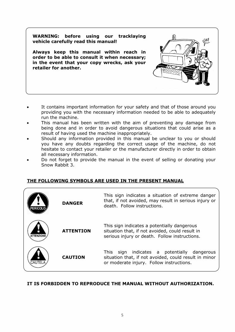
WARNING: before using our tracklaying
vehicle carefully read this manual!
Always keep this manual within reach in order to be able to consult it when necessary; in the event that your copy wrecks, ask your
retailer for another.
It contains important information for your safety and that of those around you providing you with the necessary information needed to be able to adequately run the machine.
This manual has been written with the aim of preventing any damage from being done and in order to avoid dangerous situations that could arise as a
result of having used the machine inappropriately. Should any information provided in this manual be unclear to you or should
you have any doubts regarding the correct usage of the machine, do not hesitate to contact your retailer or the manufacturer directly in order to obtain all necessary information.
Do not forget to provide the manual in the event of selling or donating your Snow Rabbit 3.
THE FOLLOWING SYMBOLS ARE USED IN THE PRESENT MANUAL
DANGER
This sign indicates a situation of extreme danger that, if not avoided, may result in serious injury or
death. Follow instructions.
ATTENTION
This sign indicates a potentially dangerous situation that, if not avoided, could result in
serious injury or death. Follow instructions.
CAUTION
This sign indicates a potentially dangerous situation that, if not avoided, could result in minor
or moderate injury. Follow instructions.
IT IS FORBIDDEN TO REPRODUCE THE MANUAL WITHOUT AUTHORIZATION.

6
1. GENERAL INFORMATION ABOUT SAFETY
1.1 DEFINITION AND GENERAL SAFETY CONDITIONS
The Instruction Manual has been written following point 1.7.4 of Regulation 98/37/CE
and taking into account the normal conditions of use of the vehicle in order to inform, together with the instructions affixed on the machine, the operators of the risks that
the machine itself presents. The customer, upon receiving the manual, agrees to have those responsible for operating, transporting and servicing the vehicle follow its contents carefully.
In this manual the following definitions of Regulation 98/37/CE are taken into
account: a)"dangerous area": any area inside or near the vehicle where the presence of a person represents a risk for the safety and health of that very individual;
b)"exposed person": any person who is entirely or partially inside a dangerous area;
c)"operator": one or more persons responsible for installing, operating, regulating, servicing, repairing, cleaning and transporting a vehicle;
Before running the machine, the operator must be acquainted with its functions, of
the position of the controls and their technical and functional specifications.
If the vehicle is used without conscientiously following the instructions reported on the manual, the manufacturer is not held liable for any damage to persons and/or things.
Do not use the vehicle after taking medicine or alcohol; it could result in an accident that could bring about serious injury or death.
Do not clean, test or regulate the machine without checking
that the engine is off and cooled down.
7
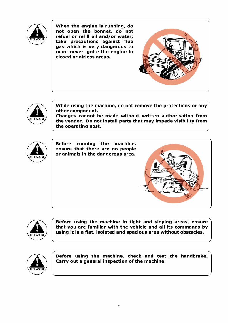
When the engine is running, do
not open the bonnet, do not refuel or refill oil and/or water;
take precautions against flue gas which is very dangerous to man: never ignite the engine in
closed or airless areas.
While using the machine, do not remove the protections or any other component.
Changes cannot be made without written authorisation from the vendor. Do not install parts that may impede visibility from
the operating post.
Before running the machine,
ensure that there are no people or animals in the dangerous area.
Before using the machine in tight and sloping areas, ensure
that you are familiar with the vehicle and all its commands by using it in a flat, isolated and spacious area without obstacles.
Before using the machine, check and test the handbrake. Carry out a general inspection of the machine.

8
Check the correct functioning of the instruments on the
instrument panel and the correct positioning of the rear-view mirrors.
Before running the vehicle, carry
out a general inspection. If you notice any abnormalities such as loose screws and the like, repair.
Check that the seatbelts are not damaged and that they function
appropriately. To fasten the seatbelt grab the
plate, insert it into the slot of
the buckle till you hear a click. Ensure that the belt is not
twisted. Push the red button on the
buckle to unfasten the belt. If after an incident the belt is ripped or damaged, substitute it
immediately.
Never try to run the machine from a position different from the driving one.
Get on and out of the driving seat only when the engine has been turned off. Before activating the hoisting lever ensure that there is no-one
present in the dangerous area.

9
1.2 OPERATING CONDITIONS
The vehicle Snow Rabbit 3 is designed to work on snow-covered ground employed as follows:
- preparation of cross country and racetracks, preparation of smaller ski slopes, ski-lift tracks, slopes for sleigh-riding
- transport of objects to cabins
- further use: mountain rescue, breeding of fauna
Its agility accounts for its capacity to run on freshly-fallen snow and its small
dimensions enable it to work in areas unlikely reached by other vehicles. Its reliability is guaranteed by the powerful engine and by the hydrostatic
transmission.
The vehicle must be used only by authorised and well-trained personnel.
1.3 CONDITIONS OF USE CONSIDERED INAPPROPRIATE OR FORBIDDEN The maximum load reported in this manual is the one estimated by the manufacturer
in order to be able to safely use the machine:
It is strictly forbidden to
overload the machine. In doing so, the mechanisms will
wear out more rapidly. When using on slopes, in particular, there may be a mechanical
breakdown or sudden loss of balance which may result in
personal injury or damage to the machine.
Stability cannot be guaranteed when loading huge objects. Even
if the maximum weight limit is respected, a large object will exceed the loading gauge. The
loads must be fastened using ropes and straps.

10
It is strictly forbidden to
transport people on the back loading platform.
It is inadvisable to use the machine on grounds with an
inclination superior to the one allowed and indicated in this manual.
It is inadvisable to use the vehicle on grounds not covered by
snow.

11
2. DESCRIPTION AND TECHNICAL DETAILS
2.1 DESCRIPTION OF THE MACHINE
Snow Rabbit 3 is made up of a tracked wagon with rubber tyre wheels (2 cogwheels and 8 smooth wheels) on which two tracks, with particular characteristics for use on
snow-covered ground, run. Each track is formed by 2 wide rubber (reinforced with canvas) bands where
transversal steel or aluminium-made hold-fasts are fixed. The steel frame can bear heavy loads through elastic suspensions.
The chassis is formed by a comfortable cabin made of steel and fibreglass. The cabin
is located at the front of the vehicle and is accessible to the operator through two lateral doors that open compass-style. Large windows and rear-view mirrors allow for an excellent visibility in all directions while the machine may be driven by using
the joystick.
An efficient heating and ventilation system blows air into the cabin through openings placed under the windscreen that can exit through the back window: this system guarantees a constant air circulation that blocks the formation of condensation on
both the windscreen as well as cabin windows.
On the instrument panel in front of the driver the instrumentation is formed by: hour-counter, fuel gauge, engine oil pressure gauge, cooling-water temperature gauge, battery charge pilot lights, preheating sparkplug pilot lights, lights and blinker
pilot lights.
A wide load-carrying platform (2,70 m2 ), which can be fitted with a canopy made of resistant material with a rear-end opening, is placed at the back of the vehicle.
The bonnet is placed immediately behind the cabin. A length-wise placement of the engine allows for an optimum use of the space available and an even distribution of
the weight.
The transmission is hydrostatic with two axial pumps with variable flow installed in tandem which work two hydraulic motors disposed directly on the driving-wheels enabling a continuous speed variation from 0 to 20 km/h.
Braking through the hydraulic system is obtained by reducing the oil flow to the
hydraulic motors until they are stopped. The hand and emergency brakes are designed in order to stop the machine whether the engine is running or off with the brakes inserted.
The auxiliary hydraulic equipment is formed by an auxiliary pump installed directly on
the endothermic engine which through a distributor controls the movements of the front equipment (frontal blade and snowplough turbine) and rear-end equipment (trailer, blade, miller, equipment for tracing cross country tracks).
Particular attention has been dedicated to the lighting system which contributes in
making nightshift work safer and easier: 2 headlights (4 upon request) on the front

12
end and another on the back end which serve to light up the miller guarantee excellent conditions of visibility. The electrical equipment includes sidelights as well as blinkers and a rotating flashing
light.
A snowplough blade is normally positioned on the vehicle at the front end whereas, upon request, a high-speed miller with a system of mechanical regulation is placed at the back end. The latter allows the machine to run on irregular trails.

13
2.2 VOLUME DIMENSIONS

14
2.3 TECHNICAL SPECIFICATIONS
Dimensions - length: 3.100 mm
- length (including frontal blade): 3.700 mm - length (including equipment for tracking): 4.500 mm - width: 1.970 mm
- height: 2.150 mm - minimum height from floor: 250 mm
Masses - mass: 1.600 kg - mass (with accessories): 1.840 kg
- total mass: 2.200 kg
Maximum carrying capacity: 480 kg
Maximum transportable weight: 700 kg
Engine:
KUBOTA V3800 DI-T-E3B 4 stroke diesel engine turbocharger
- capacity: 3.770 cc - bore x stroke: 100 x 120 mm - maximum power: 100 hp a 2.600 rpm
- maximum torque: 330 Nm a 1.300 rpm - fuel: diesel
- fuel consumption: 6 L/h - fuel tank capacity: 50 L
Hydrostatic transmission
- pump with axial pistons: 2 - capacity: 45 + 45 cm3/giro
- nominal pressure: 350 bar - hydraulic engines: 2 - Capacity: 750/565 cm3
- nominal pressure: 350 bar - speed reducer epicyclical train: ratio 1/6
- Hydraulic oil tank capacity: 24 lt
Brakes - brake: positive deceleration positiva via hydrostatic equipment; cloche control;
- service brake: hydraulically-commanded multi-disk negative parking brake; button control.
15
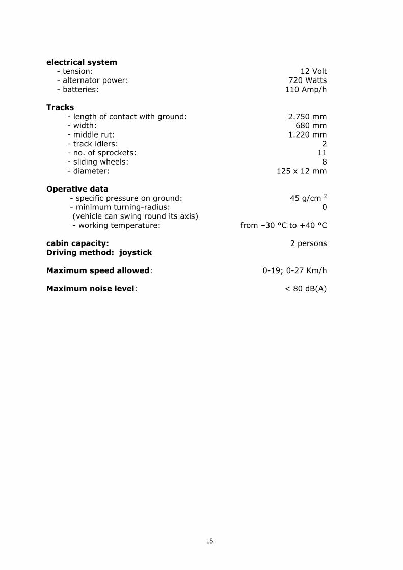
electrical system
- tension: 12 Volt - alternator power: 720 Watts
- batteries: 110 Amp/h Tracks
- length of contact with ground: 2.750 mm - width: 680 mm
- middle rut: 1.220 mm - track idlers: 2
- no. of sprockets: 11 - sliding wheels: 8 - diameter: 125 x 12 mm
Operative data
- specific pressure on ground: 45 g/cm 2
- minimum turning-radius: 0 (vehicle can swing round its axis)
- working temperature: from –30 °C to +40 °C
cabin capacity: 2 persons Driving method: joystick
Maximum speed allowed: 0-19; 0-27 Km/h
Maximum noise level: < 80 dB(A)

16
2.4 BARYCENTRE OF THE VEHICLE
In order for the operator to be able to safely run the machine, knowledge of the position of the barycentre and the maximum inclinations tolerated in the various
directions within limits of overturn of this type of machine are fundamental as the machine is normally intended to work on slope.
The co-ordinates of barycentre G noted in the above figure refer to Snow Rabbit 3
without the driver; the presence of the driver and passengers change the G position which, however, remains next to the ground in order to guarantee an excellent stability of the vehicle.
2.5 INCLINATION – SUPERABLE SLOPES
The maximum superable slope of the vehicle is, for all directions, the maximum
inclination that the machine can tolerate, maintaining a safe support on the ground and coinciding with the overturn limit. Data listed below are calculated considering the vehicle without accessories (both
anterior and back), which especially in a longitudinal position guarantee a notable stabilizing effect.
- maximum longitudinal inclination forwards: A = 55°
- maximum longitudinal inclination backwards: B = 60°
- maximum transversal inclination to the left: C = 45°
- maximum transversal inclination to the right: D = 45°

17
2.6 ACCESSORIES
Use only accessories provided by the manufacturer.
The manufacturer is NOT held responsible for problems that
may arise owing to the use of non-original accessories, the safety of which has not been put to the test by the manufacturer.

18
2.6.1 FRONTAL BLADE
The frontal blade (Foto 2) works essentially as snow plough blade.
Photo 2
The frontal blade, to be used primarily like a snowplough, is controlled by an 8-line hydraulic system which renders the following movements possible:
- lifting: the frontal blade can swing, moving upwards or downwards, within a 40° angle round a horizontal axis parallel to the ground and perpendicular to the direction of motion, moving away from the bearing surface of the machine in a controllable
way and allowing the operator to level the ground at will.

19
- inclination: the latter consists of the rotation of the blade round the axis that faces
forward; it allows for surfaces to be created with transversal inclinations different from the bearing surface of the vehicle.
- pitching: it is the rotation of the single shovel of the blade in respect to the axis
parallel to the ground and perpendicular to the forward direction; it allows the depths of the blade in different conditions of the snow (fresh or frozen) to be controlled.

20
- torsion: it is the rotation of the blade around a vertical axis perpendicular to the
ground; it allows the snow to be removed to the edges of the track or scraped from the edges and carried to the centre of the blade.
The control of the movements is carried out by means of the levers placed on the cabin platform.
2.3.2 SNOWPLOUGH TURBINE A snowplough turbine with hydraulic command can be installed on the anterior
system of lifting using the same connections as that of the shovel.
2.3.3 TRACER FOR CROSS COUNTRY TRACKS
The equipment for tracking can be installed on the same gudgeon pin of the miller
hook.
Foto 3 Foto 4

21
The tracer is lifted by the back oleodynamic piston commanded by the the two buttons of the joystick suited in the cabin control panel (Photos 8 and 11); the work-position is fixed to maintain the piston in pressure and to maintain the equipment at
a constant height.
2.6.4 TRAILER
As an option a runner trailer designed for Snow Rabbit 3 can be furnished: it can be used to transport both things as well as people having the necessary safety
equipment (roll-bar for protection and seatbelts) To know about trailer specifications, consult the respective instruction and
maintenance manual.
If the machine is used along with the runner trailer, pay utmost attention as the manoeuvrability of the machine is limited.
2.6.5 POSTERIOR FINISHER BLADE
The finisher must be fixed with a special pivot to the back system of lifting. Operation: it is lifted by the back oleo-dynamic piston commanded by the two-
positions lever placed on the cabin platform; the work-position is fixed to maintain the piston in pressure and to maintain the blade at a constant height.
Photo 5
2.6.6 MILLER
In order to apply the miller with oleodynamic command, a piston pump must be added on the joint of the pumps group. The miller must be hooked with a special gudgeon to the back lifting system that
allows for a movement of torsion and a 20° steering-lock. The oleodynamic system of the miller is composed by a 20 cm3 piston pump , a 28 cm3 piston motor and a 80-

22
litre aspiration filter as well as an idle-stop for the rotation of the miller commanded from the cabin.
Not-authorised persons are not allowed to approach the miller in movement.
Before beginning any operation, make sure that there are no
obstacles and always check that the miller is working correctly.
Be careful, when approaching the miller in movement, to avoid that parts of the body or clothes get caught in the miller.
Photo 6
The miller features a finisher and lateral flaps both in polyurethane. Flaps can be
manually curved inwards.

23

24
3. FUNCTIONS AND USE OF THE CONTROL PANEL
3.1 DRIVING DEVICES
The main driving devices ar suited on the cloche on the left hand door of the cabin (Photo 7); the others (instrumentation of accessories, post and rear equipment,
switches) are suited in the central control panel. The accelerator lever at the down right part of the control panel let you to set the rev
according to load and slopes to afford.
Photo 7 Photo 8
3.2 THE CONTROL PANEL
In the top part of the panel (Photo 9) are present the following instruments:
fuel level gauge;
tachometer; engine coolant temperature instrument;
Photo 9
The central part of the panel (Photo 10) includes:

25
Photo 10
a panel with several switches (clacson, front lights, rotating flashing light, rear
working-lights, pre-heated switches)
Ignition key. The working bkrake red button
Another panel with several switches (cabin air fan, cabin heating, windscreen wiper, miller rotation)
The lower part of the panel features (Photo 8):
a joystick for the control of the frontal and rear equipment; the joystick controls: - the lifting movement of the blade: upwards moving the joystick forward,
downwards moving the joystick back; - the torsion movement of the blade: to the right tilting the joystick to the right,
forward, to the left tilting the joystick to the left; - the tilting downward of the blade: to the left switching the red button on the
left, to the right switching the red button on the right;
- the movement of the rear oleodynamic piston (where tracking equipment, miller and finisher are connected to) upwards pushing the frontal yellow
button, downwards pushing the rear yellow button the engine acceleration lever: push it forward to decrease the engine rev. the fuse box.
The housing for tracers for cross-country tracks, possibly installed on the rear miller.

26
4. PRELIMINARY TESTS
Attention: always check the vehicle before using to verify the
safety conditions! Follow instructions regarding the
control and maintenance of the machine as reported in the manual:
the failure of which may increase the risk of being involved in an
accident or damaging the vehicle.
4.1 REFUELING
4.1.1 FUEL
Recommended type: see instruction manual regarding the engine. Verify, through the fuel gauge placed on the instrument panel, that there is an adequate quantity of fuel in the tank. The filler cap is on the left side of the machine.
An electric pump protected by a netting pre-filter supplies diesel to the engine. The
pre-filter is placed between the pump and the tank, and need to be substituted if clogged.
Attention: do not excessively fill the tank. Do not fuel when the engine is warm or running and close the filler cap well.
Fuel increases its volume when heated: if the level is excessive it could overflow and come into contact with the muffler and/or other warm parts as well as with the electric wiring causing
serious fire hazard!

27
4.1.2 HYDRAULIC OIL Check the level of hydraulic oil in the tank of the hydrostatic transmission system; fill
up the tank (placed in the rear part of the machine, under the loading plan) if necessary.
Check also the eventual presence of oil leaks.
4.1.3 ENGINE OIL
Control its level and fill it up if necessary. Type and quantity: see instruction manual regarding the engine.
4.2 ENDOTHERMIC ENGINE
For preliminary tests on the engine refer to the instruction manual.
4.3 ELECTRICAL SYSTEM
Carefully test that lights function especially prior to night
excursions.
Check the level of the electrolyte in the battery: if necessary fill up with distilled water. Do not use running water as it
contains mineral salt which can damage the battery. When the battery must be substituted, be sure the voltage,
capacity, seat dimensions and weight are the same as that of the original.
FIRST AID: Batteries contain sulphuric acid,
that following contact with skin provoke serious burns. In case of an accident, provide first aid
treatment and immediately consult your doctor.
- Contact of sulphuric acid with skin or eyes: rinse with water for 10-15 minutes.
- Ingestion: drink an abundant quantity of water or milk.
- Acid sprayed on clothes: immediately remove contaminated clothes.

28
4.4 FRAME
Control the condition of all components and eventually replace the damaged ones. Check the tightening of screws, clamps and various fasteners;
repair if necessary.
4.5 TRACKS
Check that its strain is correct: for eventual adjustments see chapter 7.
Check that conditions of track links and the hold-fasts are well fastened: if not, replace the damaged components.
4.6 CONTROLS AND INSTRUMENTATION
Check that the steering-lever moves freely and that it is
positioned in the centre; check that the hand brake is inserted: this guarantees that there is no oil flow to the engines and
permits a safe starting of the machine. Verify that the levers controlling the accessories (anterior and
back) are able to move freely and are placed in central position and hence, disconnected.
Check that the accelerator lever can slide freely in its slot; if it
is blocked or cannot slide freely repair. With the ignition key in position 1, check that all the
instruments on the instrument panel work correctly and do not present any functional abnormalities.
Adjust the rear-view mirrors. Check that seat belts work adequately and fasten.

29
5. USE OF THE VEHICLE
Attention: carefully read the manual in order to understand the working of the controls!
Should anything be unclear, contact your retailer! The loss of control of the vehicle can cause accidents or injuries.
5.1 STARTING OF THE ENGINE After having carried out the preliminary operations described in the previous chapter,
start the engine following the instructions reported in the manual. Hold the button of the pre-heated candle power placed in the central part of the control panel for 20
secs. Turn the ignition key clockwise. Before moving the vehicle wait until the temperature of the coolant reaches at least 40° C: check on the temperature indicator set on the instruments panel.
5.2 MOVEMENT Place the switch that releases the brake to the off position: in this way the hand
brake is unblocked and the levers that command the tracks are activated. Acceleration, deceleration, braking and steering of the vehicle are controlled by the
position of the levers that regulate oil-flow to the motors and not from the accelerator lever: therefore handle the levers gently. Proceed very slowly the first
few metres when you move.
Always verify that in the radius of
action of the vehicle there are neither obstacles nor people.
Attention: if one reverses incorrectly, you can run into
obstacles or persons with the risk of hurting them. Therefore, move
slowly and prudently.

30
5.3 PARKING
The vehicle must be parked on an
even ground with the engine turned off and the hand brake
inserted: avoid, if possible, parking in sloping areas as they are considered dangerous because
the vehicle could move risking an accident.
If it is necessary to park in sloping areas, park the vehicle sideways, insert the hand brake and eventually lower the blade; in any case do not park on so steep slopes
which cannot be easily crossed on foot. Slowly stop the vehicle by gently pulling on the lever.
Stop the engine, insert the hand brake and get out of the vehicle with caution.

31
6. SUGGESTIONS FOR DRIVING
6.1 GENERALITIES
The vehicle Snow Rabbit 3 is destined to operate on steep slopes as well. As a result and considering its particular driving system, it is necessary to provide some
suggestions about the driving techniques to allow the operator to use the vehicle in a safe way.
Read this manual carefully especially what regards safety! Always drive with prudence and common sense.
To begin with, if you have never driven one beforehand, ask someone experienced to teach you some techniques. Initially, learn to perform the manoeuvres at slow speed, even if you already consider
yourself experienced: do not try to use it at the limit of performances until having become familiar with the vehicle!
Get in and out of the vehicle only
with the engine turned off. NEVER try to run the vehicle from positions that are not the driving
seat. Always fasten the seat-belt:
besides protecting in case the vehicle should overturn, they help the driver maintain control of the
vehicle itself. Avoid carrying out difficult
manoeuvres (acceleration-deceleration-curves). Do not strive to entertain: you could flip
over and get injured!
To take confidence with your Snow Rabbit 3 choose a flat zone, well snow-capped,
without obstacles of any kind and possibly without other vehicles running.
6.2 HOW TO BEGIN
Follow the instructions about the starting of the motor.
Warm up a few minutes and bring the accelerator lever to about ¾ of the run; release the hand brake with the appropriate switch and, at the same time, move the
engine control lever forward slowly and gently: the oil flow will increase and the vehicle will gain speed.

32
If you want to slow down (brake), move the lever in the opposite direction (backwards). Move the lever gently.
Neither accelerate nor slow down or brake too abruptly in order to avoid risking loss of control of the vehicle: avoid driving at a high speed.
6.3 HOW TO STEER
The simplest way to steer is by operating only one engine: the left one to go to the
right and vice versa. Once you have acquired familiarity with the vehicle, you can differentiate the flows: more elevated ones to the right engine to go to the left and
vice versa. In this way the manoeuvre can be measured out; however, it is delicate and its effects also depend on the compactness of the snow.
The results of this technique vary according to the type of ground: on slippery ground or one that slows the driver down, the way to act is different.
Sudden variations of speed, braking abruptly or excessive speed in connection with the radius of curvature can result in
loss of control of the vehicle: in this case bring the engine lever back to the central position.
6.4 HOW TO TACKLE SLOPES
Avoid both slopes considered too
steep as well as those having obstacles. Avoid those with slippery conditions and those
which slow down driving as they could compromise one’s ability to
control the vehicle and result in the vehicle turning over with serious consequences.
Before facing slopes, be certain to have acquired enough experience in driving on flatland.
If your Snow Rabbit 3 slows down quite a bit or stops altogether and you believe, however, that you are able to reach the peak of the slope, insert the hand brake, restart the engine, release the hand brake and start accelerating gradually to avoid
skidding.

33
6.5 HOW TO FACE DESCENTS Driving the vehicle downhill, maintain the oil-flow rate low to exploit the motor brake.
If it is possible, face the descent proceeding in a straight line carefully choosing the path and moderating the speed to be able to control the vehicle if faced with
obstacles or the unexpected.
Avoid dangerous bends that can cause lateral skidding.
6.6 HOW TO CROSS SLOPING GROUND
Avoid crossing slippery slopes or those that slow down driving.
Avoid carrying out 90° turns both uphill as well as downhill.
On grounds that slow down driving, in order to maintain the direction, it might be necessary to adjust the tracks.
If the machine appears to turn over, steer slightly downwards until stable; then head upwards once again.
6.7 DRIVING ON ROUGH GROUND
Proceed with extreme caution and at a low speed paying
attention to eventual obstacles which can damage the vehicle or compromise its stability.
6.8 DRIVING ON SLIPPERY OR FROZEN GROUND
On this type of ground, it is
necessary to pay the utmost attention: sudden and unexpected
slides can provoke accidents. Avoid abrupt manoeuvres!
If the tracks begin to slide, gently steer in the direction that the vehicle is sliding.

34
7. SETTINGS AND PERIODICAL MAINTENANCE
Periodic inspections, regulations and lubrications will maintain your Snow Rabbit 3 in the best of conditions from the point of view of safety and efficiency.
The most important parts to be checked listed below are placed under the loading panel, which can be easily lifted, thanks to two gas springs. It is possible to lift forward the front cabin: it is not equipped with gas springs, so it need the
collaboration of two persons to complete the lifting.
SAFETY IS A MUST FOR THE OWNER OF THE VEHICLE!
Do not work on the machine with the engine running! Clothes could
get caught in moving parts and electric components can cause
shocks or start fires.
7.1 ENGINE
Various settings required: refer to the engine Manual.
The engine silencer deteriorates through use. When it becomes too noisy turn to your local reseller for its substitution.
It is important to check the level of the coolant in the tank (Photo 21), and top it up
if necessary. In the case of frequent top-ups check the presence of losses.
Photo 21

35
7.2 HYDROSTATIC TRANSMISSION
Check the level of hydraulic liquid every month: fill up if necessary. In the case of frequent top-ups check the presence of losses.
Substitute the suction oil filter (Photo 22) after the first 80 working hours. Then substitute every 500 hours.
Substitute the hydraulic liquid every year. Unscrew the ¾ cap (Photo 23) to complete the top-up.
Photo 22 Photo 23
Recommended oils: ISO vg 46 viscosity (32 for very cold temperatures). It is possible to use oil a.t.f. as well. In any case do not mix the different types of oil.
Temperature TEXACO BP ESSO SHELL MOBIL ISO
Rating
20 – 40 ° C RANDO HLP 32 NUTO H32 TELLUS 37 DTE 24 32
40 – 50 ° C RANDO HD46 HLP 46 NUTO H46 TELLUS 46 DTE 25 46
50 – 60 ° C RANDO HD68 HLP 68 NUTO H68 TELLUS 68 DTE 26 68
60 – 70 ° C RANDO HD 100 HLP 100 NUTO H100 TELLUS 100 DTE 26 100
Check power circuit pressures (to be carried out on a yearly basis).
Using a pressure gauge with an adequate scale (50 bar), inserted in the proper ¼ gas joint (see (1)
in Photo 24), check the pressure at the feed pump system outlet;
optimal value: 20 bar. Using a pressure gauge with an
adequate scale (600 bar), inserted
in the proper joint (see (1) in Photo 24), check the pressure at
the tracks command engine feed pump; optimal value: 0-350 bar.
If pressure results are not correct, see
your retailer. Photo 24
2
1

36
7.3 AUXILIARY HYDROSTATIC SYSTEM The auxiliary hydrostatic system is constitued by an auxiliary pump placed directly on
the endothermic engine, that, through a distributor, controls the movements of the equipment installed (frontal blade, snowplough turbine, trailers, finisher, miller,
trackers for ski cross-country tracks). The electric valve controlling the heating system in the cabin is placed on the diesel
engine (Photo 25). If a malfuncioning in the heating system is found, please check this component.
Photo 25
Using a pressure gauge with an adequate scale (150 bar), inserted in the proper joint
(see (3) in Photo 26), yearly check the pressure on the discharge of the frontal lifting cylinder (frontal blade); optimal value: 90 bar. If the pressure value is not correct, adjust the regulation screw situated on the electric valve block (see (4) in Photo 27).
If you don’t have a pressure joint, you can do an empiric adjustment, placing a 80 kg
weight on the frontal blade, and adjust the screw (4) until it is possible the lifting movement of the blade is re-established.

37
Photo 26 Photo 27
If a tracking equipment on the back lifting system is installed, it is also necessary to
adjust the working depth adjusting the screw (see (5) in Photo 28) that tensions the spring placed on the drawbar of the tracer equipment.
Foto 28 Foto 29
When you install the miller on the back lifting, it is also necessary to adjust the working depth adjusting the pull chain crank which controls the position of the miller
roller (see (6) in Photo 29).
5
6
3
4

38
7.4 TRACKS 7.4.1 REGULATING TENSION
The tension of the tracks can be regulated in two ways:
A - loosen the two locking screws and using a torque wrench, tighten the screws of the track stretcher, situated in proximity of the anterior carrying wheel, to about 1,5kgm; retighten the two locking screws.
B - lift the vehicle; loosen the two locking screws and using a normal wrench tighten the screws of the track stretcher, located in proximity of the anterior carrying wheel,
until its ‘curvature’ reaches the distance of about 5 cm from the two central wheels; retighten the two locking screws.
7.4.2 ASSEMBLY AND DISASSEMBLY
To disassemble the tracks lift the machine up at least 10 cm from the ground using
the anterior and back lifting devices in addition to some hydraulic jacks. After ensuring its stability, loosen the screws of the track stretcher (2 block, 1
tension) and dismount the two back cogwheels: the track can be removed sideways.
If it were not possible to lift the vehicle, the track junction could be opened (see Photo 30); open it and let the machine run over it.
Photo 30

39
7.5 CONTROL AND LUBRICATION OF THE GREASING POINTS To grease the track stretcher arm on the first idler wheel, remove the wheel shaft
after having taken away the track; put new grease on (graphite type) and re-assemble.
The lubrication of the two track-tightener axis operating on the first front wheel is really
important. After removing the track, take the wheel-holding tube, lubricate it with new
grease (graphite type) and re-install all the components.
Photo 31
Other points of greasing are located on the trapeze of the anterior blade lifting and on all the front and back lifting and moving cylinders.
7.6 ELECTRICAL SYSTEM
Periodically check the level of the liquid in the battery: if necessary, fill up with distilled water.
Attention: the battery electrolyte is toxic. It can cause serious burns as it contains sulphuric acid. Avoid contact with skin,
eyes and clothing. In case of accidental contact, wash abundantly with running
water; if swallowed, drink a lot of milk and consult a doctor.
Keep battery away from heat
sources such as a flame. Be careful that tools do not touch battery terminals in order to
avoid sparks.

40
7.7 OTHER ADJUSTMENTS
Adjustment of the front light: The depth of the lights can be changed adjusting the three screws.
Adjust the tension of the alternator belt:
per registrare la corretta tensione della cinghia dell’alternatore agire
sulla barra tendi-cinghia tramite le due viti.
Electric connection for the engine heating (when present): Snow Rabbit 3 can be equipped
with a electric pre-heater of the diesel engine. In the case of
extreme outside temperature plug the cable in the socket (220 V).
Safety rear body support arm:
After lifting the rear body, secure it through the support arm linked to
the frame.

41
Safety locking of the frontal cabin support arm: after lifting the cabin, secure it using the
support arm connected to the frame. Plug the locking pin in the
apposite hole to avoid the cabin to move or fall.
Locking the frontal cabin: to assure the frontal cabin in the proper position check the blocking
screw is fast fixed to the base on the back of the cabin.
Locking the rear body: Check the blocking screw is fast
fixed to the relative base placed on the bottom of the rear body.
Adjustment of the door closing position: Adjust the lever near the door
closure to increase or decrease the closure lock extension.

42
8. TRANSPORT, CLEANING AND GARAGING
8.1 TRANSPORT
Given its dimensions, Snow Rabbit 3 can be easily transported with an adequate
truck. Loading and unloading can be effected using a pair of loading ramps of adequate dimensions and carrying capacity.
8.2 CLEANING
A frequent cleaning of Snow Rabbit 3 not only improves its appearance, but also
increases its efficiency as well as the duration of many components. It is particularly advisable to wash the machine frequently during the winter in order to eliminate possible residues of salt that could corrode the metallic parts.
To clean the car:
- use a continual flow of water. Use the necessary pressure without being excessive: an excessive pressure can provoke infiltration and deteriorate mechanical and electrical parts;
- when most part of the dirt and grease has come away, subsequently wash with lukewarm water and soap (possibly neutral);
- an old brush or a cleaning rod can be useful in cleaning the less accessible parts;
- rinse with clean water and dry;
- eventually apply a protective wax for automobiles on the painted parts; - avoid cleansing waxes: some of them contain abrasives that can ruin the
varnish; - avoid acids and solvents for the same reason.
Finally start the engine and let it run for a few minutes.
8.3 GARAGING
For long period garaging (over 60 days), after having washed, prepare the machine as follows:
- follow the manufacturer’s instructions as regards to the engine - lubricate all the command cables
- place a plastic bag on the outlet of the muffler to prevent dampness - if the machine must remain in a damp or salty place, cover all metal parts (but
not the rubber and the plastic!) with a light coating of oil.
If the machine needs to be repaired, do so before garaging!

43
8.4 DEMOLITION
Respect the laws in force in the country where the vehicle is being used, in regards to use and scrapping of products used for cleaning and maintenance of the vehicle.
In case the vehicle should be demolished, comply with the anti-pollution regulations set in the country where the vehicle is being used. In particular, in regards to highly
polluting elements such as batteries, have specialised companies dispose of them.
Remove the battery Empty the engine and hydraulic oil and diesel oil tanks
Disassemble the machine and divide parts and components according to their manufacturing kind
Provide for the disposal of the parts in authorized centres, with particular
attention for the most polluting parts: batteries, fuel, lubricant.
Remember that the vendor and the importer are always available to answer any questions.

44
DRAWING ELECTRICAL SYSTEM

45
DRAWING HYDROSTATIC SYSTEM CPL

46
DRAWING HYDROSTATIC TRANSMISSION
CPL

47
DRAWING AUXILIARY HYDROSTATIC SYSTEM

48
FAVERO LORENZO s.a.s. & C.
COSTRUZIONE MACCHINE NEVE
Via delle industrie, 1 31040 Trevignano (TV) Italy
Tel/Fax + 39-0423-677110 www.faverolorenzo.com