operating guide vlt soft starter mcd 500 · the vlt® soft starter mcd 500 is an advanced digital...
TRANSCRIPT

ENGINEERING TOMORROW
Operating GuideVLT® Soft Starter MCD 500
vlt-drives.danfoss.com


Contents
1 Introduction 6
2 Safety 11
2.1 Safety 11
3 Installation 13
3.1 Mechanical Installation 13
3.2 Dimensions and Weight 14
4 Electrical Installation 16
4.1 Control Wiring 16
4.1.1 Ways to Control the Soft Starter 16
4.1.2 Control Terminals 16
4.1.3 Remote Inputs 16
4.1.4 Serial Communication 17
4.1.5 Ground Terminal 17
4.1.6 Power Terminations 17
4.1.7 Finger Guard Kit 18
4.2 Power Input and Output Configurations 18
4.2.1 Internally Bypassed Models (MCD5-0021B to MCD5-0961B) 18
4.2.2 MCD5-0245C 19
4.2.3 MCD5-0360C to MCD5-1600C 19
4.3 Motor Connection 19
4.3.1 Testing the Installation 20
4.3.2 In-line Installation 20
4.3.2.1 Internally Bypassed 20
4.3.2.2 Non-bypassed 20
4.3.2.3 Externally Bypassed 20
4.3.3 Inside Delta Installation 21
4.3.3.1 Internally Bypassed 21
4.3.3.2 Non-bypassed 22
4.3.3.3 Externally Bypassed 22
4.4 Current Ratings 23
4.4.1 In-line Connection (Bypassed) 24
4.4.2 In-line Connection (Non-bypassed/Continuous) 25
4.4.3 Inside Delta Connection (Bypassed) 26
4.4.4 Inside Delta Connection (Non-bypassed/Continuous) 27
4.5 Minimum and Maximum Current Settings 28
4.6 Bypass Contactor 28
4.7 Main Contactor 28
Contents Operating Guide
MG17K802 Danfoss A/S © 03/2018 All rights reserved. 1

4.8 Circuit Breaker 28
4.9 Power Factor Correction 29
4.10 Fuses 29
4.10.1 Power Supply Fuses 29
4.10.2 Bussmann Fuses 30
4.10.3 Ferraz Fuses 32
4.10.4 UL Fuse Selection and Short Circuit Ratings 34
4.11 Schematic Diagrams 37
5 Product Features 39
5.1 Motor Overload Protection 39
5.2 Adaptive Control 39
5.3 Starting Modes 40
5.3.1 Constant Current 40
5.3.2 Current Ramp 40
5.3.3 Adaptive Control 40
5.3.4 Kick-start 41
5.4 Stopping Modes 41
5.4.1 Coast to Stop 41
5.4.2 TVR Soft Stop 41
5.4.3 Adaptive Control 42
5.4.4 Pump Stopping 42
5.4.5 Brake 42
5.5 Jog Operation 43
5.6 Inside Delta Operation 44
5.7 Typical Start Currents 45
5.8 Installation with Main Contactor 46
5.9 Installation with Bypass Contactor 47
5.10 Emergency Run Operation 48
5.11 Auxiliary Trip Circuit 49
5.12 DC Brake with External Zero-speed Sensor 50
5.13 Soft Braking 51
5.14 Two-speed Motor 52
6 Operation 54
6.1 Control Methods 54
6.2 Operation and LCP 55
6.2.1 Operating Modes 55
6.3 Remote-mounted LCP 56
6.3.1 Synchronizing the LCP and the Soft Starter 56
6.4 Welcome Screen 56
Contents VLT® Soft Starter MCD 500
2 Danfoss A/S © 03/2018 All rights reserved. MG17K802

6.5 Local Control Keys 56
6.6 Displays 56
6.6.1 Temperature Monitoring Screen (S1) 57
6.6.2 Programmable Screen (S2) 57
6.6.3 Average Current (S3) 57
6.6.4 Current Monitoring Screen (S4) 57
6.6.5 Frequency Monitoring Screen (S5) 57
6.6.6 Motor Power Screen (S6) 57
6.6.7 Last Start Information (S7) 57
6.6.8 Date and Time (S8) 57
6.6.9 SCR Conduction Bar Graph 58
6.6.10 Performance Graphs 58
7 Programming 59
7.1 Access Control 59
7.2 Quick Menu 59
7.2.1 Quick Set-up 59
7.2.2 Application Set-up Examples 60
7.2.3 Loggings 61
7.3 Main Menu 61
7.3.1 Parameters 61
7.3.2 Parameter Shortcut 61
7.3.3 Parameter List 62
8 Parameter Descriptions 63
8.1 Primary Motor Settings 63
8.1.1 Brake 64
8.2 Protection 65
8.2.1 Current Imbalance 65
8.2.2 Undercurrent 65
8.2.3 Instant Overcurrent 65
8.2.4 Frequency Trip 65
8.3 Inputs 66
8.4 Outputs 67
8.4.1 Relay A Delays 67
8.4.2 Relays B and C 67
8.4.3 Low Current Flag and High Current Flag 68
8.4.4 Motor Temperature Flag 68
8.4.5 Analog Output A 68
8.5 Start/Stop Timers 69
8.6 Auto-reset 69
Contents Operating Guide
MG17K802 Danfoss A/S © 03/2018 All rights reserved. 3

8.6.1 Auto-reset Delay 70
8.7 Secondary Motor Set 70
8.8 Display 71
8.8.1 User-programmable Screen 71
8.8.2 Performance Graphs 72
8.9 Restricted Parameters 72
8.10 Protection Action 74
8.11 Factory Parameters 74
9 Tools 75
9.1 Set Date and Time 75
9.2 Load/Save Settings 75
9.3 Reset Thermal Model 75
9.4 Protection Simulation 76
9.5 Output Signal Simulation 76
9.6 Digital I/O State 76
9.7 Temp Sensors State 76
9.8 Alarm Log 77
9.8.1 Trip Log 77
9.8.2 Event Log 77
9.8.3 Counters 77
10 Troubleshooting 78
10.1 Trip Messages 78
10.2 General Faults 83
11 Specifications 85
11.1 UL-compliant Installation 86
11.1.1 Models MCD5-0021B to MCD5-0105B 86
11.1.2 Models MCD5-0131B to MCD5-0215B 86
11.1.3 Models MCD5-0245B to MCD5-0396B 86
11.1.4 Models MCD5-0245C 86
11.1.5 Models MCD5-0360C to MCD5-1600C 87
11.1.6 Models MCD5-0469B to MCD5-0961B 87
11.1.7 Pressure Terminal/Connector Kits 87
11.2 Accessories 87
11.2.1 LCP Remote Mounting Kit 87
11.2.2 Communication Modules 87
11.2.3 PC Software 87
11.2.4 Finger Guard Kit 88
11.2.5 Surge Protection Kit (Lightning Protection) 88
Contents VLT® Soft Starter MCD 500
4 Danfoss A/S © 03/2018 All rights reserved. MG17K802
12 Busbar Adjustment Procedure (MCD5-0360C to MCD5-1600C) 89
13 Appendix 91
13.1 Symbols, Abbreviations, and Conventions 91
Index 92
Contents Operating Guide
MG17K802 Danfoss A/S © 03/2018 All rights reserved. 5

1 Introduction
The VLT® Soft Starter MCD 500 is an advanced digital softstart solution for 11–850 kW (15–1150 hp) motors. The softstarters provide a complete range of motor and systemprotection features and are designed for reliableperformance in the most demanding installation situations.
1.1.1 Document Version
This operating guide is regularly reviewed and updated. Allsuggestions for improvement are welcome. Table 1.1 showsthe document version.
Edition Remarks
MG17K8xx Instruction about using finger guard kits for IP00installations added to chapter 4 Electrical Installation.
Table 1.1 Document Version
1.1.2 Feature List
Models for all connection requirements• 21–1600 A (in-line connection).
• In-line or inside delta connection.
• Internally bypassed up to 961 A.
• Mains voltage: 200–525 V AC or 380–690 V AC.
• Control voltage: 24 V AC/V DC, 110–120 V AC, or220–240 V AC.
User-friendly LCP• Loggings.
• Real-time graphs.
• SCR conduction bar graph.
Tools• Application set-ups.
• Date and time stamped event log with 99 entries.
• 8 most recent trips.
• Counters.
• Protection simulation.
• Output signal simulation.
Inputs and outputs• Local or remote control input options.
(3 x fixed, 1 x programmable).
• Relay outputs (3 x programmable).
• Analog programmable output.
• 24 V DC 200 mA supply output.
Start and run modes• Adaptive control.
• Constant current.
• Current ramp.
• Kick-start.
• Jog.
• Emergency run operation.
Stop modes• Adaptive deceleration control.
• Timed voltage ramp soft stop.
• DC brake.
• Soft brake.
• Starter disable.
Other features• Autostart/stop timer.
• Second-order thermal model.
Introduction VLT® Soft Starter MCD 500
6 Danfoss A/S © 03/2018 All rights reserved. MG17K802
11
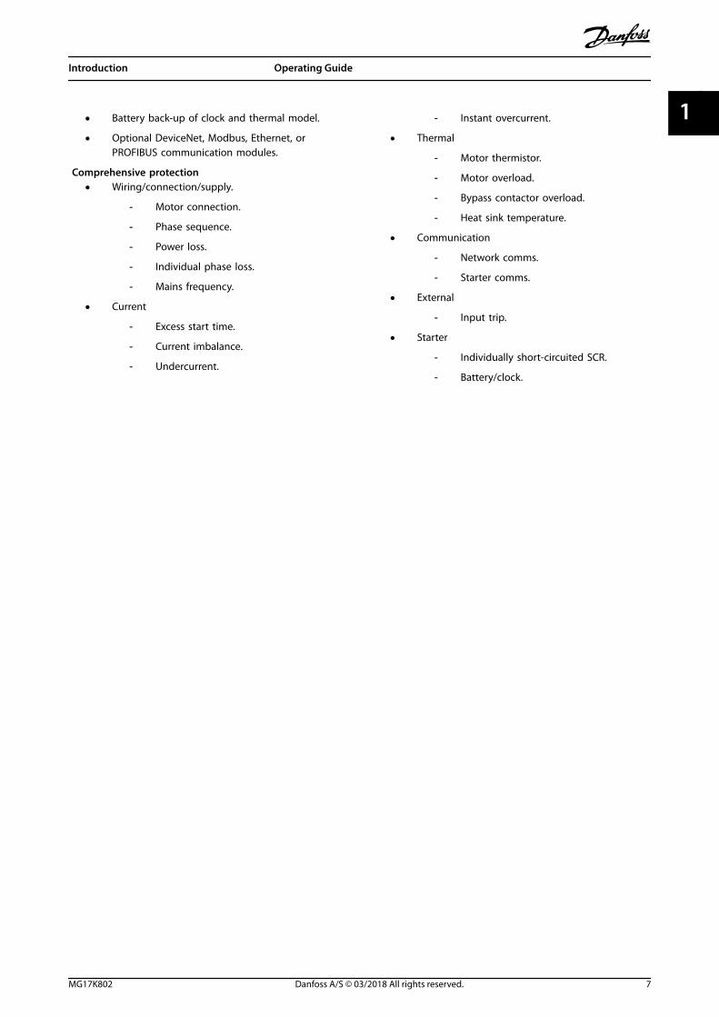
• Battery back-up of clock and thermal model.
• Optional DeviceNet, Modbus, Ethernet, orPROFIBUS communication modules.
Comprehensive protection• Wiring/connection/supply.
- Motor connection.
- Phase sequence.
- Power loss.
- Individual phase loss.
- Mains frequency.
• Current
- Excess start time.
- Current imbalance.
- Undercurrent.
- Instant overcurrent.
• Thermal
- Motor thermistor.
- Motor overload.
- Bypass contactor overload.
- Heat sink temperature.
• Communication
- Network comms.
- Starter comms.
• External
- Input trip.
• Starter
- Individually short-circuited SCR.
- Battery/clock.
Introduction Operating Guide
MG17K802 Danfoss A/S © 03/2018 All rights reserved. 7
1 1
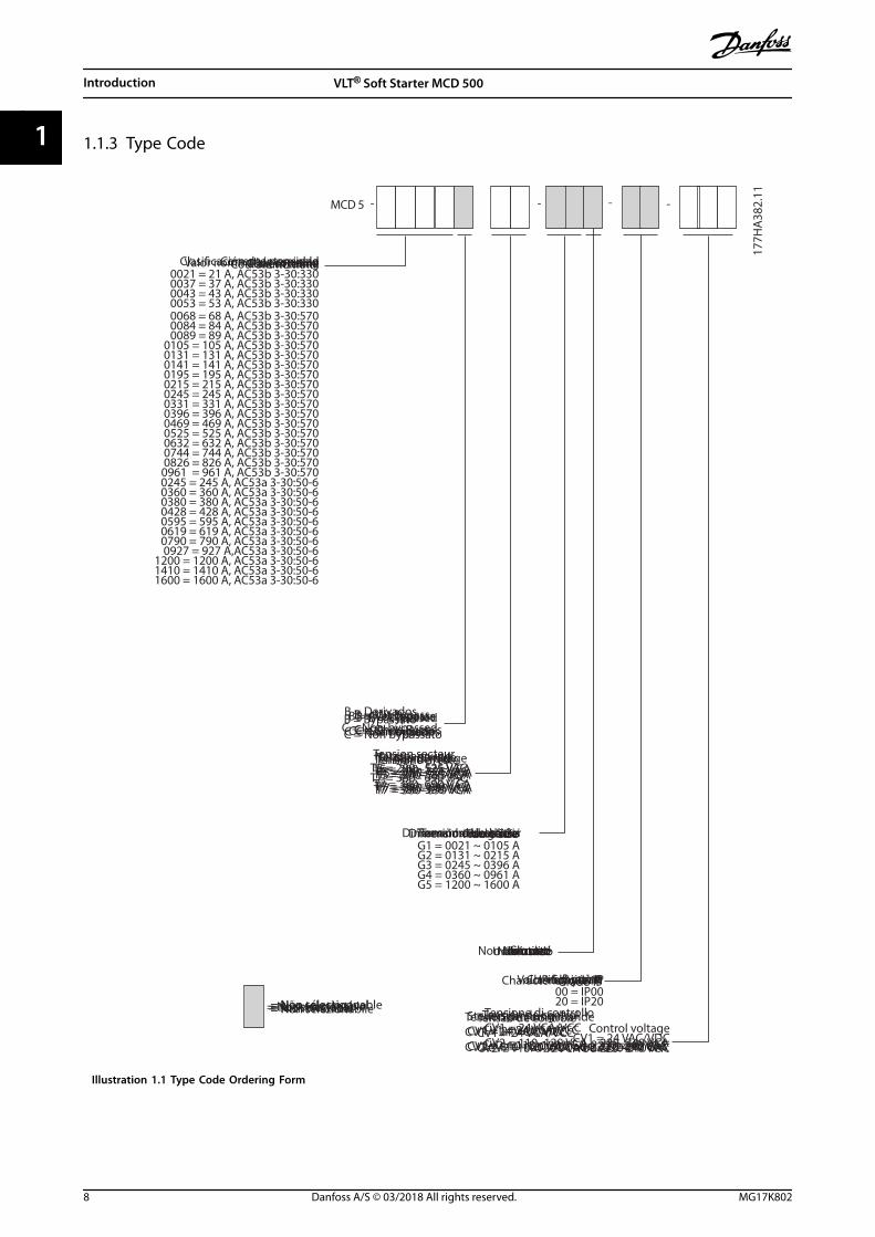
1.1.3 Type Code
MCD 5 - - - -
0021 = 21 A, AC53b 3-30:3300037 = 37 A, AC53b 3-30:3300043 = 43 A, AC53b 3-30:3300053 = 53 A, AC53b 3-30:3300068 = 68 A, AC53b 3-30:5700084 = 84 A, AC53b 3-30:5700089 = 89 A, AC53b 3-30:570
0105 = 105 A, AC53b 3-30:5700131 = 131 A, AC53b 3-30:5700141 = 141 A, AC53b 3-30:5700195 = 195 A, AC53b 3-30:5700215 = 215 A, AC53b 3-30:5700245 = 245 A, AC53b 3-30:5700331 = 331 A, AC53b 3-30:5700396 = 396 A, AC53b 3-30:5700469 = 469 A, AC53b 3-30:5700525 = 525 A, AC53b 3-30:5700632 = 632 A, AC53b 3-30:5700744 = 744 A, AC53b 3-30:5700826 = 826 A, AC53b 3-30:5700961 = 961 A, AC53b 3-30:570
00 = IP0020 = IP20
G1 = 0021 ~ 0105 AG2 = 0131 ~ 0215 AG3 = 0245 ~ 0396 AG4 = 0360 ~ 0961 AG5 = 1200 ~ 1600 A
0245 = 245 A, AC53a 3-30:50-6 0360 = 360 A, AC53a 3-30:50-6 0380 = 380 A, AC53a 3-30:50-6 0428 = 428 A, AC53a 3-30:50-6 0595 = 595 A, AC53a 3-30:50-6 0619 = 619 A, AC53a 3-30:50-6 0790 = 790 A, AC53a 3-30:50-6 0927 = 927 A,AC53a 3-30:50-6
1200 = 1200 A, AC53a 3-30:50-6 1410 = 1410 A, AC53a 3-30:50-6 1600 = 1600 A, AC53a 3-30:50-6
177H
A38
2.11
Current rating
B = BypassedC = Non-bypassed
Mains voltageT5 = 200 - 525 VACT7 = 380 - 690 VAC
Frame size
= Not selectable
Not used
IP rating
Control voltageCV1 = 24 VAC/VDC
CV2 = 110-120 VAC or 220-240 VAC
Valor nominal da corrente
B = Derivados
C = Não derivados
Tensão de redeT5 = 200–525 VCAT7 = 380–690 VCA
Tamanho do chassi
Não usado
Valor nominal IP
Tensão de controleCV1 = 24 VCA/VCCCV2 = 110–120 VCA ou 220–240 VCA
= Não selecionável
Courant nominal
B = Avec bipasseC = Sans bipasse
Tension secteurT5 = 200–525 V CAT7 = 380–690 V CA
Dimensions du châssis
Inutilisé
Charactéristique IP
Tension de commmandeCV1 = 24 V CA/V CCCV2 = 110–120 V CA ou 220–240 V CA
= Non sélectionnable
Nennstrom
B = Mit BypassC = Ohne Bypass
NetzspannungT5 = 200–525 VACT7 = 380–690 VAC
Baugröße
Unbenutzt
IP-Schutzart
SteuerspannungCV1 = 24 VAC/VDCCV2 = 110–120 VAC oder 220–240 VAC
= Nicht wählbar
Corrente nominale
B = BypassatoC = Non bypassato
Tensione di reteT5 = 200–525 VCAT7 = 380–690 VCA
Dimensioni del telaio
Non utilizzato
Grado IP
Tensione di controlloCV1 = 24 VCA/VCCCV2 = 110–120 VCA o 220–240 VCA
= Non selezionabile
Clasi�cación de intensidad
B = Con bypassC = Sin bypass
Tensión de redT5 = 200–525 VCAT7 = 380–390 VCA
Tamaño de bastidor
Sin uso
Clasi�cación IP
Tensión de controlCV1 = 24 VCA/VCCCV2 = 110–120 VCA o 220–240 VCA
= No seleccionable
Illustration 1.1 Type Code Ordering Form
Introduction VLT® Soft Starter MCD 500
8 Danfoss A/S © 03/2018 All rights reserved. MG17K802
11
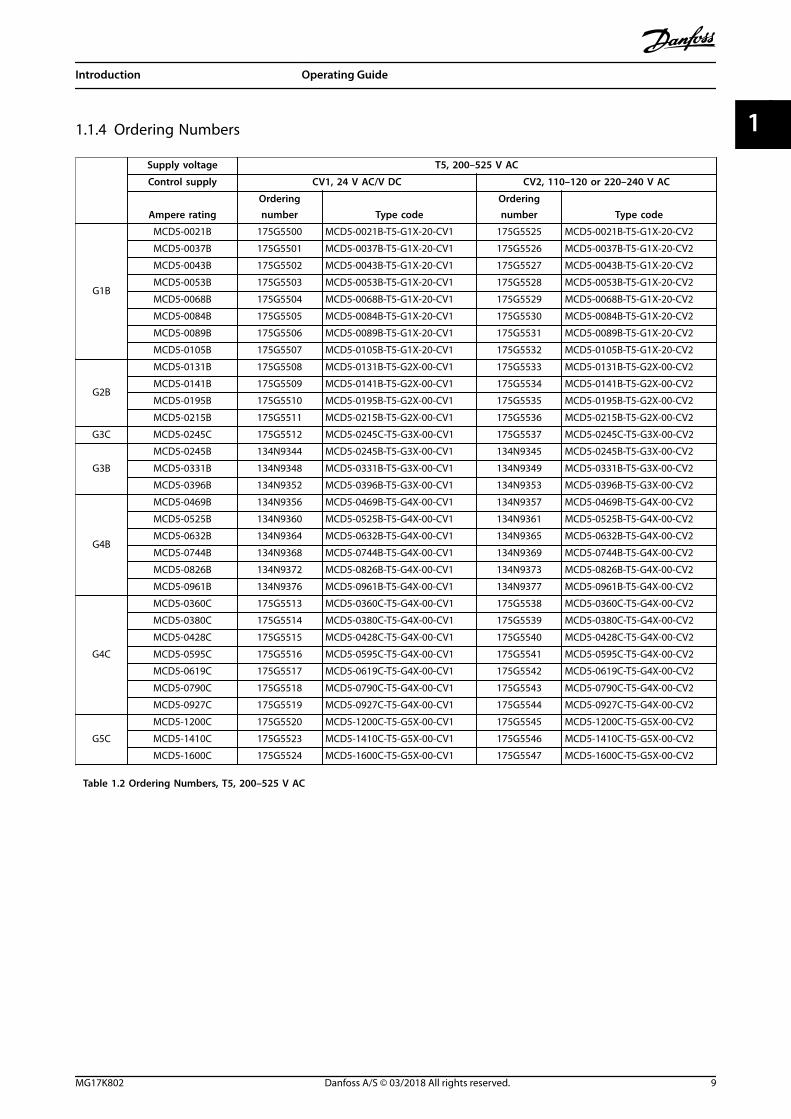
1.1.4 Ordering Numbers
Supply voltage T5, 200–525 V AC
Control supply CV1, 24 V AC/V DC CV2, 110–120 or 220–240 V AC
Ampere ratingOrderingnumber Type code
Orderingnumber Type code
G1B
MCD5-0021B 175G5500 MCD5-0021B-T5-G1X-20-CV1 175G5525 MCD5-0021B-T5-G1X-20-CV2
MCD5-0037B 175G5501 MCD5-0037B-T5-G1X-20-CV1 175G5526 MCD5-0037B-T5-G1X-20-CV2
MCD5-0043B 175G5502 MCD5-0043B-T5-G1X-20-CV1 175G5527 MCD5-0043B-T5-G1X-20-CV2
MCD5-0053B 175G5503 MCD5-0053B-T5-G1X-20-CV1 175G5528 MCD5-0053B-T5-G1X-20-CV2
MCD5-0068B 175G5504 MCD5-0068B-T5-G1X-20-CV1 175G5529 MCD5-0068B-T5-G1X-20-CV2
MCD5-0084B 175G5505 MCD5-0084B-T5-G1X-20-CV1 175G5530 MCD5-0084B-T5-G1X-20-CV2
MCD5-0089B 175G5506 MCD5-0089B-T5-G1X-20-CV1 175G5531 MCD5-0089B-T5-G1X-20-CV2
MCD5-0105B 175G5507 MCD5-0105B-T5-G1X-20-CV1 175G5532 MCD5-0105B-T5-G1X-20-CV2
G2B
MCD5-0131B 175G5508 MCD5-0131B-T5-G2X-00-CV1 175G5533 MCD5-0131B-T5-G2X-00-CV2
MCD5-0141B 175G5509 MCD5-0141B-T5-G2X-00-CV1 175G5534 MCD5-0141B-T5-G2X-00-CV2
MCD5-0195B 175G5510 MCD5-0195B-T5-G2X-00-CV1 175G5535 MCD5-0195B-T5-G2X-00-CV2
MCD5-0215B 175G5511 MCD5-0215B-T5-G2X-00-CV1 175G5536 MCD5-0215B-T5-G2X-00-CV2
G3C MCD5-0245C 175G5512 MCD5-0245C-T5-G3X-00-CV1 175G5537 MCD5-0245C-T5-G3X-00-CV2
G3B
MCD5-0245B 134N9344 MCD5-0245B-T5-G3X-00-CV1 134N9345 MCD5-0245B-T5-G3X-00-CV2
MCD5-0331B 134N9348 MCD5-0331B-T5-G3X-00-CV1 134N9349 MCD5-0331B-T5-G3X-00-CV2
MCD5-0396B 134N9352 MCD5-0396B-T5-G3X-00-CV1 134N9353 MCD5-0396B-T5-G3X-00-CV2
G4B
MCD5-0469B 134N9356 MCD5-0469B-T5-G4X-00-CV1 134N9357 MCD5-0469B-T5-G4X-00-CV2
MCD5-0525B 134N9360 MCD5-0525B-T5-G4X-00-CV1 134N9361 MCD5-0525B-T5-G4X-00-CV2
MCD5-0632B 134N9364 MCD5-0632B-T5-G4X-00-CV1 134N9365 MCD5-0632B-T5-G4X-00-CV2
MCD5-0744B 134N9368 MCD5-0744B-T5-G4X-00-CV1 134N9369 MCD5-0744B-T5-G4X-00-CV2
MCD5-0826B 134N9372 MCD5-0826B-T5-G4X-00-CV1 134N9373 MCD5-0826B-T5-G4X-00-CV2
MCD5-0961B 134N9376 MCD5-0961B-T5-G4X-00-CV1 134N9377 MCD5-0961B-T5-G4X-00-CV2
G4C
MCD5-0360C 175G5513 MCD5-0360C-T5-G4X-00-CV1 175G5538 MCD5-0360C-T5-G4X-00-CV2
MCD5-0380C 175G5514 MCD5-0380C-T5-G4X-00-CV1 175G5539 MCD5-0380C-T5-G4X-00-CV2
MCD5-0428C 175G5515 MCD5-0428C-T5-G4X-00-CV1 175G5540 MCD5-0428C-T5-G4X-00-CV2
MCD5-0595C 175G5516 MCD5-0595C-T5-G4X-00-CV1 175G5541 MCD5-0595C-T5-G4X-00-CV2
MCD5-0619C 175G5517 MCD5-0619C-T5-G4X-00-CV1 175G5542 MCD5-0619C-T5-G4X-00-CV2
MCD5-0790C 175G5518 MCD5-0790C-T5-G4X-00-CV1 175G5543 MCD5-0790C-T5-G4X-00-CV2
MCD5-0927C 175G5519 MCD5-0927C-T5-G4X-00-CV1 175G5544 MCD5-0927C-T5-G4X-00-CV2
G5C
MCD5-1200C 175G5520 MCD5-1200C-T5-G5X-00-CV1 175G5545 MCD5-1200C-T5-G5X-00-CV2
MCD5-1410C 175G5523 MCD5-1410C-T5-G5X-00-CV1 175G5546 MCD5-1410C-T5-G5X-00-CV2
MCD5-1600C 175G5524 MCD5-1600C-T5-G5X-00-CV1 175G5547 MCD5-1600C-T5-G5X-00-CV2
Table 1.2 Ordering Numbers, T5, 200–525 V AC
Introduction Operating Guide
MG17K802 Danfoss A/S © 03/2018 All rights reserved. 9
1 1

Supply voltage T7, 380–690 V AC
Control supply CV1, 24 V AC/V DC CV2, 110–120 or 220–240 V AC
Ampere ratingOrderingnumber Type code
Orderingnumber Type code
G1B
MCD5-0021B 175G5548 MCD5-0021B-T7-G1X-20-CV1 175G5571 MCD5-0021B-T7-G1X-20-CV2
MCD5-0037B 175G5549 MCD5-0037B-T7-G1X-20-CV1 175G5572 MCD5-0037B-T7-G1X-20-CV2
MCD5-0043B 175G5550 MCD5-0043B-T7-G1X-20-CV1 175G5573 MCD5-0043B-T7-G1X-20-CV2
MCD5-0053B 175G5551 MCD5-0053B-T7-G1X-20-CV1 175G5574 MCD5-0053B-T7-G1X-20-CV2
MCD5-0068B 175G5552 MCD5-0068B-T7-G1X-20-CV1 175G5575 MCD5-0068B-T7-G1X-20-CV2
MCD5-0084B 175G5553 MCD5-0084B-T7-G1X-20-CV1 175G5576 MCD5-0084B-T7-G1X-20-CV2
MCD5-0089B 175G5554 MCD5-0089B-T7-G1X-20-CV1 175G5577 MCD5-0089B-T7-G1X-20-CV2
MCD5-0105B 175G5555 MCD5-0105B-T7-G1X-20-CV1 175G5578 MCD5-0105B-T7-G1X-20-CV2
G2B
MCD5-0131B 175G5556 MCD5-0131B-T7-G2X-00-CV1 175G5579 MCD5-0131B-T7-G2X-00-CV2
MCD5-0141B 175G5557 MCD5-0141B-T7-G2X-00-CV1 175G5580 MCD5-0141B-T7-G2X-00-CV2
MCD5-0195B 175G5558 MCD5-0195B-T7-G2X-00-CV1 175G5581 MCD5-0195B-T7-G2X-00-CV2
MCD5-0215B 175G5559 MCD5-0215B-T7-G2X-00-CV1 175G5582 MCD5-0215B-T7-G2X-00-CV2
G3C MCD5-0245C 175G5560 MCD5-0245C-T7-G3X-00-CV1 175G5583 MCD5-0245C-T7-G3X-00-CV2
G3B
MCD5-0245B 134N9346 MCD5-0245B-T7-G3X-00-CV1 134N9347 MCD5-0245B-T7-G3X-00-CV2
MCD5-0331B 134N9350 MCD5-0331B-T7-G3X-00-CV1 134N9351 MCD5-0331B-T7-G3X-00-CV2
MCD5-0396B 134N9354 MCD5-0396B-T7-G3X-00-CV1 134N9355 MCD5-0396B-T7-G3X-00-CV2
G4B
MCD5-0469B 134N9358 MCD5-0469B-T7-G4X-00-CV1 134N9359 MCD5-0469B-T7-G4X-00-CV2
MCD5-0525B 134N9362 MCD5-0525B-T7-G4X-00-CV1 134N9363 MCD5-0525B-T7-G4X-00-CV2
MCD5-0632B 134N9366 MCD5-0632B-T7-G4X-00-CV1 134N9367 MCD5-0632B-T7-G4X-00-CV2
MCD5-0744B 134N9370 MCD5-0744B-T7-G4X-00-CV1 134N9371 MCD5-0744B-T7-G4X-00-CV2
MCD5-0826B 134N9374 MCD5-0826B-T7-G4X-00-CV1 134N9375 MCD5-0826B-T7-G4X-00-CV2
MCD5-0961B 134N9378 MCD5-0961B-T7-G4X-00-CV1 134N9379 MCD5-0961B-T7-G4X-00-CV2
G4C
MCD5-0360C 175G5561 MCD5-0360C-T7-G4X-00-CV1 175G5584 MCD5-0360C-T7-G4X-00-CV2
MCD5-0380C 175G5562 MCD5-0380C-T7-G4X-00-CV1 175G5585 MCD5-0380C-T7-G4X-00-CV2
MCD5-0428C 175G5563 MCD5-0428C-T7-G4X-00-CV1 175G5586 MCD5-0428C-T7-G4X-00-CV2
MCD5-0595C 175G5564 MCD5-0595C-T7-G4X-00-CV1 175G5587 MCD5-0595C-T7-G4X-00-CV2
MCD5-0619C 175G5565 MCD5-0619C-T7-G4X-00-CV1 175G5588 MCD5-0619C-T7-G4X-00-CV2
MCD5-0790C 175G5566 MCD5-0790C-T7-G4X-00-CV1 175G5589 MCD5-0790C-T7-G4X-00-CV2
MCD5-0927C 175G5567 MCD5-0927C-T7-G4X-00-CV1 175G5590 MCD5-0927C-T7-G4X-00-CV2
G5C
MCD5-1200C 175G5568 MCD5-1200C-T7-G5X-00-CV1 175G5591 MCD5-1200C-T7-G5X-00-CV2
MCD5-1410C 175G5569 MCD5-1410C-T7-G5X-00-CV1 175G5592 MCD5-1410C-T7-G5X-00-CV2
MCD5-1600C 175G5570 MCD5-1600C-T7-G5X-00-CV1 175G5593 MCD5-1600C-T7-G5X-00-CV2
Table 1.3 Ordering Numbers, T7, 380–690 V AC
Introduction VLT® Soft Starter MCD 500
10 Danfoss A/S © 03/2018 All rights reserved. MG17K802
11

2 Safety
2.1 Safety
The following symbols are used in this guide:
WARNINGIndicates a potentially hazardous situation that couldresult in death or serious injury.
CAUTIONIndicates a potentially hazardous situation that couldresult in minor or moderate injury. It can also be used toalert against unsafe practices.
NOTICEIndicates important information, including situations thatcan result in damage to equipment or property.
2.1.1 Qualified Personnel
Correct and reliable transport, storage, installation,operation, and maintenance are required for the trouble-free and safe operation of the soft starter. Only qualifiedpersonnel are allowed to install or operate this equipment.
Qualified personnel is defined as trained staff, who areauthorized to install, commission, and maintain equipment,systems, and circuits in accordance with pertinent laws andregulations. Additionally, the personnel must be familiarwith the instructions and safety measures described in thismanual.
WARNINGELECTRICAL SHOCK HAZARDVLT® Soft Starter MCD 500 contains dangerous voltageswhen connected to mains voltage. Only a qualifiedelectrician should carry out the electrical installation.Improper installation of the motor or the soft starter cancause death, serious injury, or equipment failure. Followthe guidelines in this manual and local electrical safetycodes.Models MCD5-0360C ~ MCD5-1600C:Treat the busbar and heat sink as live parts wheneverthe unit has mains voltage connected (including whenthe soft starter is tripped or waiting for a command).
WARNINGPROPER GROUNDINGDisconnect the soft starter from mains voltage beforecarrying out repair work.It is the responsibility of the person installing the softstarter to provide proper grounding and branch circuitprotection according to local electrical safety codes.Do not connect power factor correction capacitors to theoutput of the VLT® Soft Starter MCD 500. If static powerfactor correction is employed, it must be connected tothe supply side of the soft starter.
WARNINGIMMEDIATE STARTIn auto-on mode, the motor can be controlled remotely(via remote inputs) while the soft starter is connected tomains.MCD5-0021B ~ MCD5-0961B:Transportation, mechanical shock, or rough handlingmay cause the bypass contactor to latch into the Onstate.
To prevent the motor from starting immediately on firstcommissioning or operation after transportation:
• Always ensure that the control supply is appliedbefore the power.
• Applying control supply before power ensuresthat the contactor state is initialized.
WARNINGUNINTENDED STARTWhen the soft starter is connected to AC mains, DCsupply, or load sharing, the motor can start at any time.Unintended start during programming, service, or repairwork can result in death, serious injury, or propertydamage. The motor can start with an external switch, afieldbus command, an input reference signal from theLCP or LOP, via remote operation using MCD PCSoftware, or after a cleared fault condition.
To prevent unintended motor start:• Press [Off]/[Reset] on the LCP before
programming parameters.
• Disconnect the soft starter from mains.
• Completely wire and assemble the soft starter,motor, and any driven equipment beforeconnecting the soft starter to AC mains, DCsupply, or load sharing.
Safety Operating Guide
MG17K802 Danfoss A/S © 03/2018 All rights reserved. 11
2 2

WARNINGSAFETY OF PERSONNELThe soft starter is not a safety device and does notprovide electrical isolation or disconnection from thesupply.
• If isolation is required, the soft starter must beinstalled with a main contactor.
• Do not rely on the start and stop functions forsafety of personnel. Faults occurring in themains supply, the motor connection, or theelectronics of the soft starter can causeunintended motor starts or stops.
• If faults occur in the electronics of the softstarter, a stopped motor may start. A temporaryfault in the supply mains or loss of motorconnection can also cause a stopped motor tostart.
To provide safety of personnel and equipment, controlthe isolation device through an external safety system.
NOTICEBefore changing any parameter settings, save the currentparameter to a file using MCD PC Software or the SaveUser Set function.
NOTICEUse the autostart feature with caution. Read all the notesrelated to autostart before operation.
The examples and diagrams in this manual are includedsolely for illustrative purposes. The information containedin this manual is subject to change at any time andwithout prior notice. Responsibility or liability is neveraccepted for direct, indirect, or consequential damageresulting from the use or application of this equipment.
Safety VLT® Soft Starter MCD 500
12 Danfoss A/S © 03/2018 All rights reserved. MG17K802
22
3 Installation
3.1 Mechanical Installation
177H
A42
7.10
1
2
3
4
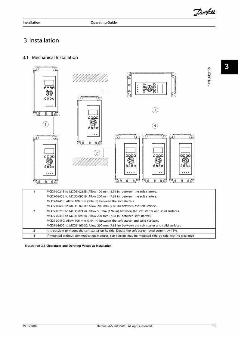
1 MCD5-0021B to MCD5-0215B: Allow 100 mm (3.94 in) between the soft starters.MCD5-0245B to MCD5-0961B: Allow 200 mm (7.88 in) between the soft starters.MCD5-0245C: Allow 100 mm (3.94 in) between the soft starters.MCD5-0360C to MCD5-1600C: Allow 200 mm (7.88 in) between the soft starters.
2 MCD5-0021B to MCD5-0215B: Allow 50 mm (1.97 in) between the soft starter and solid surfaces.MCD5-0245B to MCD5-0961B: Allow 200 mm (7.88 in) between soft starters.MCD5-0245C: Allow 100 mm (3.94 in) between the soft starter and solid surfaces.MCD5-0360C to MCD5-1600C: Allow 200 mm (7.88 in) between the soft starter and solid surfaces.
3 It is possible to mount the soft starter on its side. Derate the soft starter rated current by 15%.
4 If mounted without communication modules, soft starters may be mounted side by side with no clearance.
Illustration 3.1 Clearances and Derating Values at Installation
Installation Operating Guide
MG17K802 Danfoss A/S © 03/2018 All rights reserved. 13
3 3
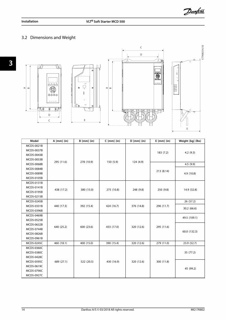
3.2 Dimensions and Weight
A B
D
C E
A B
C
D
E
177H
A51
4.10
Model A [mm] (in) B [mm] (in) C [mm] (in) D [mm] (in) E [mm] (in) Weight [kg] (lbs)
MCD5-0021B
295 (11.6) 278 (10.9) 150 (5.9) 124 (4.9)
183 (7.2) 4.2 (9.3)MCD5-0037BMCD5-0043BMCD5-0053B
MCD5-0068B
213 (8.14)
4.5 (9.9)
MCD5-0084B
4.9 (10.8)MCD5-0089BMCD5-0105B
MCD5-0131B
438 (17.2) 380 (15.0) 275 (10.8) 248 (9.8) 250 (9.8) 14.9 (32.8)MCD5-0141BMCD5-0195BMCD5-0215B
MCD5-0245B
440 (17.3) 392 (15.4) 424 (16.7) 376 (14.8) 296 (11.7)
26 (57.2)
MCD5-0331B30.2 (66.6)
MCD5-0396B
MCD5-0469B
640 (25.2) 600 (23.6) 433 (17.0) 320 (12.6) 295 (11.6)
49.5 (109.1)MCD5-0525BMCD5-0632B
60.0 (132.3)MCD5-0744BMCD5-0826BMCD5-0961B
MCD5-0245C 460 (18.1) 400 (15.0) 390 (15.4) 320 (12.6) 279 (11.0) 23.9 (52.7)
MCD5-0360C
689 (27.1) 522 (20.5) 430 (16.9) 320 (12.6) 300 (11.8)
35 (77.2)MCD5-0380CMCD5-0428CMCD5-0595C
45 (99.2)MCD5-0619CMCD5-0790CMCD5-0927C
Installation VLT® Soft Starter MCD 500
14 Danfoss A/S © 03/2018 All rights reserved. MG17K802
33
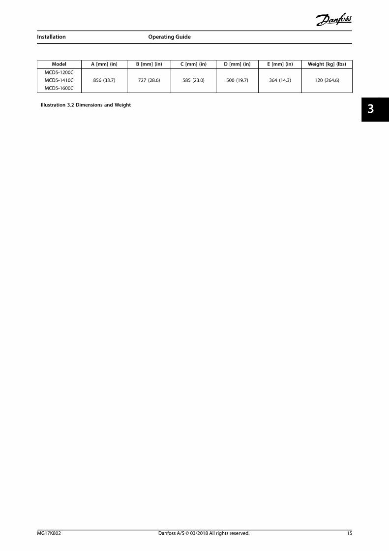
Model A [mm] (in) B [mm] (in) C [mm] (in) D [mm] (in) E [mm] (in) Weight [kg] (lbs)
MCD5-1200C856 (33.7) 727 (28.6) 585 (23.0) 500 (19.7) 364 (14.3) 120 (264.6)MCD5-1410C
MCD5-1600C
Illustration 3.2 Dimensions and Weight
Installation Operating Guide
MG17K802 Danfoss A/S © 03/2018 All rights reserved. 15
3 3
4 Electrical Installation
4.1 Control Wiring
4.1.1 Ways to Control the Soft Starter
Control the VLT® Soft Starter MCD 500 in 3 ways:• Pressing the keys on the LCP.
• Via remote inputs.
• Via a serial communication link.
The soft starter always responds to a local start or stopcommand (via the [Hand On] and [Off] keys on the LCP).Pressing the [Auto On] key selects remote control (the softstarter accepts commands from the remote inputs). Inremote mode, the Auto On LED is on. In hand-on mode,the Hand On LED is on if the soft starter starts or runs. TheOff LED is on if the soft starter is stopped or stops.
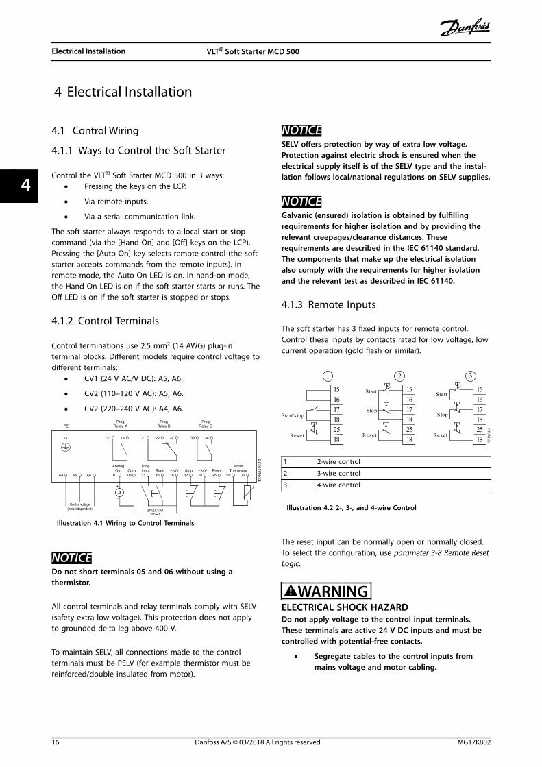
4.1.2 Control Terminals
Control terminations use 2.5 mm2 (14 AWG) plug-interminal blocks. Different models require control voltage todifferent terminals:
• CV1 (24 V AC/V DC): A5, A6.
• CV2 (110–120 V AC): A5, A6.
• CV2 (220–240 V AC): A4, A6.
Illustration 4.1 Wiring to Control Terminals
NOTICEDo not short terminals 05 and 06 without using athermistor.
All control terminals and relay terminals comply with SELV(safety extra low voltage). This protection does not applyto grounded delta leg above 400 V.
To maintain SELV, all connections made to the controlterminals must be PELV (for example thermistor must bereinforced/double insulated from motor).
NOTICESELV offers protection by way of extra low voltage.Protection against electric shock is ensured when theelectrical supply itself is of the SELV type and the instal-lation follows local/national regulations on SELV supplies.
NOTICEGalvanic (ensured) isolation is obtained by fulfillingrequirements for higher isolation and by providing therelevant creepages/clearance distances. Theserequirements are described in the IEC 61140 standard.The components that make up the electrical isolationalso comply with the requirements for higher isolationand the relevant test as described in IEC 61140.
4.1.3 Remote Inputs
The soft starter has 3 fixed inputs for remote control.Control these inputs by contacts rated for low voltage, lowcurrent operation (gold flash or similar).
1 7 7 H
A 5 0
4 . 1 0
S t a r t / s t o p
R e s e t
S t a r t
S t o p
R e s e t
S t a r t
S t o p
R e s e t
1 5 1 6 1 7 1 8 2 5 1 8
1 5 1 6 1 7 1 8 2 5 1 8
1 5 1 6 1 7 1 8 2 5 1 8
2 3 1
1 2-wire control
2 3-wire control
3 4-wire control
Illustration 4.2 2-, 3-, and 4-wire Control
The reset input can be normally open or normally closed.To select the configuration, use parameter 3-8 Remote ResetLogic.
WARNINGELECTRICAL SHOCK HAZARDDo not apply voltage to the control input terminals.These terminals are active 24 V DC inputs and must becontrolled with potential-free contacts.
• Segregate cables to the control inputs frommains voltage and motor cabling.
Electrical Installation VLT® Soft Starter MCD 500
16 Danfoss A/S © 03/2018 All rights reserved. MG17K802
44
4.1.4 Serial Communication
Control via the serial communication network is alwaysenabled in hand-on mode and can be enabled or disabledin remote control mode (see parameter 3-2 Comms inRemote). Control via the serial communication networkrequires an optional communication module.
4.1.5 Ground Terminal
Ground terminals are at the back of the soft starter.
• MCD5-0021B to MCD5-0105B have 1 terminal onthe input side (top).
• MCD5-0131B to MCD5-0961B and MCD5-0245C toMCD5-1600C have 2 terminals; 1 on the inputside (top), and 1 on the output side (bottom).
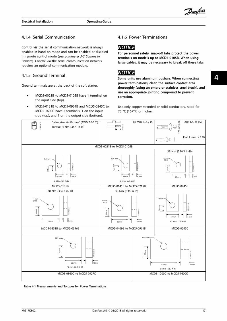
4.1.6 Power Terminations
NOTICEFor personnel safety, snap-off tabs protect the powerterminals on models up to MCD5-0105B. When usinglarge cables, it may be necessary to break off these tabs.
NOTICESome units use aluminum busbars. When connectingpower terminations, clean the surface contact areathoroughly (using an emery or stainless steel brush), anduse an appropriate jointing compound to preventcorrosion.
Use only copper stranded or solid conductors, rated for75 °C (167°F) or higher.
177H
A64
6.10 Cable size: 6–50 mm2 (AWG 10-1/0)
Torque: 4 Nm (35.4 in-lb)
177H
A64
7.10
14 mm (0.55 in)
177H
A64
8.10 Torx T20 x 150
177H
A64
9.10 Flat 7 mm x 150
MCD5-0021B to MCD5-0105B
38 Nm (336.3 in-lb)
5 mm
15 m
m
28 mm
11 mm(M10)
177H
A64
3.10
MCD5-0131B MCD5-0141B to MCD5-0215B MCD5-0245B
38 Nm (336.3 in-lb) 38 Nm (336 in-lb)
6 mm
15 m
m
28 mm
11 mm(M10)
177H
A64
4.10
13 mm
12 m
m
32 mm
11 mm(M10)
177H
A64
5.10
MCD5-0331B to MCD5-0396B MCD5-0469B to MCD5-0961B MCD5-0245C
MCD5-0360C to MCD5-0927C MCD5-1200C to MCD5-1600C
Table 4.1 Measurements and Torques for Power Terminations
Electrical Installation Operating Guide
MG17K802 Danfoss A/S © 03/2018 All rights reserved. 17
4 4

4.1.7 Finger Guard Kit
NOTICEWhen installing IP00 soft starters (MCB5-131B andabove), finger guards are specified for personnel safety.Finger guards fit over the soft starter terminals toprevent accidental contact with live terminals. Fingerguards provide IP20 protection when correctly installed.
• MCD5-0131B to MCD5-0215B: 175G5662.
• MCD5-0245B to MCD5-0396B: 175G5730.
• MCD5-0469B to MCD5-0961B: 175G5731.
• MCD5-245C: 175G5663.
• MCD5-0360C to MCD5-0927C: 175G5664.
• MCD5-1200C to MCD5-1600C: 175G5665.
NOTICETo be UL-compliant, the models MCD5-0131B toMCD5-0396B require finger guards.
4.2 Power Input and Output Configurations
4.2.1 Internally Bypassed Models(MCD5-0021B to MCD5-0961B)
Models MCD5-0021B to MCD5-0215B have power inputs atthe top of the unit and outputs at the bottom of the unit.
Internally bypassed models MCD5-0245B to MCD5-0396Bhave output busbars at the bottom of the unit and inputbusbars at both the top and bottom. The AC supply canbe connected:
• Top-in/bottom-out.
• Bottom-in/bottom-out
Internally bypassed models MCD5-0469B to MCD5-0961Bhave input and output busbars at the top and bottom ofthe unit. The AC supply can be connected:
• Top-in/bottom-out.
• Top-in/top-out.
• Bottom-in/bottom-out.
• Bottom-in/top-out.
1/L1, 3/L2, 5/L3
2/T1, 4/T2, 6/T3
177H
A68
6.10
Illustration 4.3 MCD5-0021B to MCD5-0105B, 21–105 A
1/L1 3/L2 5/L3
2/T1 4/T2 6/T3
177H
A68
7.10
Illustration 4.4 MCD5-0131B to MCD5-0215B, 131–215 A
2/T1 4/T2 6/T31/L1 3/L2 5/L3
1/L1 3/L2 5/L3
177H
A68
8.10
Illustration 4.5 MCD5-0245B to MCD5-0396B, 245–396 A
Electrical Installation VLT® Soft Starter MCD 500
18 Danfoss A/S © 03/2018 All rights reserved. MG17K802
44

20.0
2/T1 4/T2 6/T31/L1 3/L2 5/L3
2/T1 4/T2 6/T31/L1 3/L2 5/L3
177H
A65
0.11
Illustration 4.6 MCD5-0469B to MCD5-0961B, 469–961 A
4.2.2 MCD5-0245C
MCD5-0245C has dedicated bypass terminals at the bottomof the unit. The bypass terminals are:
• T1B.
• T2B.
• T3B.
177H
A65
1.10
1/L1 3/L2 5/L3
T1B T2B T3B2/T1 4/T2 6/T3
Illustration 4.7 Bypass Terminals on MCD5-0245C, 245 A
4.2.3 MCD5-0360C to MCD5-1600C
MCD5-0360C to MCD5-1600C have dedicated bypassterminals on the input busbars. The bypass terminals are:
• L1B.
• L2B.
• L3B.
The busbars on non-bypassed models MCD5-0360C toMCD5-1600C can be adjusted for top or bottom input andoutput as required. See chapter 12 Busbar AdjustmentProcedure (MCD5-0360C to MCD5-1600C) for step-by-stepinstructions. The soft starters are manufactured top-in/bottom-out.
NOTICEFor models MCD5-0360C to MCD5-1600C to be UL-compliant, mount them top-in/bottom-out, or top-out/bottom-in. See chapter 11.1 UL-compliant Installation formore information.
(L1B L2B L3B)1/L1 3/L2 5/L3
2/T1 4/T2 6/T3
1/L1 3/L2 5/L3(L1B L2B L3B)
2/T1 4/T2 6/T3
(L1B L2B L3B) 1/L1 3/L2 5/L3
2/T1 4/T2 6/T3
1/L1 3/L2 5/L3(L1B L2B L3B)
2/T1 4/T2 6/T3
177H
A65
2.10
Illustration 4.8 Location of Bypass Terminals, MCD5-0360C toMCD5-1600C, 360–1600 A
4.3 Motor Connection
VLT® Soft Starters MCD 500 can be connected to themotor in-line or inside delta (also called 3-wire and 6-wireconnection). When connecting in inside delta, enter themotor full load current (FLC) in parameter 1-1 Motor FullLoad Current. The MCD 500 automatically calculates insidedelta current based on this data. Parameter 15-7 MotorConnection is set to Auto Detect as default and can be setto force the soft starter in inside delta or in-line.
Electrical Installation Operating Guide
MG17K802 Danfoss A/S © 03/2018 All rights reserved. 19
4 4
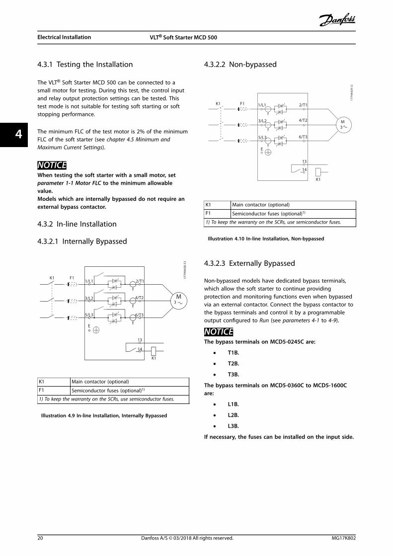
4.3.1 Testing the Installation
The VLT® Soft Starter MCD 500 can be connected to asmall motor for testing. During this test, the control inputand relay output protection settings can be tested. Thistest mode is not suitable for testing soft starting or softstopping performance.
The minimum FLC of the test motor is 2% of the minimumFLC of the soft starter (see chapter 4.5 Minimum andMaximum Current Settings).
NOTICEWhen testing the soft starter with a small motor, setparameter 1-1 Motor FLC to the minimum allowablevalue.Models which are internally bypassed do not require anexternal bypass contactor.
4.3.2 In-line Installation
4.3.2.1 Internally Bypassed
177H
A43
0.12
M3
6/T3
2/T1
5/L3
3/L2
1/L1
13
14
4/T2
E
K1
K1 F1
K1 Main contactor (optional)
F1 Semiconductor fuses (optional)1)
1) To keep the warranty on the SCRs, use semiconductor fuses.
Illustration 4.9 In-line Installation, Internally Bypassed
4.3.2.2 Non-bypassed
177H
A42
9.12
6/T3
2/T1
5/L3
3/L2
1/L1
13
14
4/T2
E
K1
K1 F1
M3
K1 Main contactor (optional)
F1 Semiconductor fuses (optional)1)
1) To keep the warranty on the SCRs, use semiconductor fuses.
Illustration 4.10 In-line Installation, Non-bypassed
4.3.2.3 Externally Bypassed
Non-bypassed models have dedicated bypass terminals,which allow the soft starter to continue providingprotection and monitoring functions even when bypassedvia an external contactor. Connect the bypass contactor tothe bypass terminals and control it by a programmableoutput configured to Run (see parameters 4-1 to 4-9).
NOTICEThe bypass terminals on MCD5-0245C are:
• T1B.
• T2B.
• T3B.
The bypass terminals on MCD5-0360C to MCD5-1600Care:
• L1B.
• L2B.
• L3B.
If necessary, the fuses can be installed on the input side.
Electrical Installation VLT® Soft Starter MCD 500
20 Danfoss A/S © 03/2018 All rights reserved. MG17K802
44

177H
A61
7.11
M3
F1
6/T3
2/T1
5/L3
3/L2
1/L1
13
14
4/T2
E
K1
K1
T1B
T2B
T3B
K2
34
33
K2
K1 Main contactor
K2 Bypass contactor (external)
F1 Semiconductor fuses (optional)1)
1) To keep the warranty on the SCRs, use semiconductor fuses.
Illustration 4.11 In-line Installation, Externally Bypassed,MCD5-0245C
177H
A43
1.12
M3
F1
6/T3
2/T1
5/L3
3/L2
1/L1
13
14
4/T2
E
K1
K1
L1B
L2B
L3B
K2
34
33
K2
K1 Main contactor
K2 Bypass contactor (external)
F1 Semiconductor fuses (optional)1)
1) To keep the warranty on the SCRs, use semiconductor fuses.
Illustration 4.12 In-line Installation, Externally Bypassed,MCD5-0360C to MCD5-1600C
4.3.3 Inside Delta Installation
NOTICEWhen connecting the VLT® Soft Starter MCD 500 ininside delta configuration, always install a maincontactor or shunt trip circuit breaker.
NOTICEWhen connecting in inside delta, enter the motor fullload current (FLC) in parameter 1-1 Motor FLC. The MCD500 automatically calculates inside delta currents basedon this data. Parameter 15-7 Motor Connection is set toAuto detect as default and can be set to force the softstarter in inside delta or in-line.
4.3.3.1 Internally Bypassed
6/T
2/T
13
14
4/T
K1
U1(1) U2(4)
V1(2) V2(5)
W1(3) W2(6)
5/L3
3/L2
1/L1
E
K1 F1
M3
177H
A50
1.11
K1 Main contactor
F1 Semiconductor fuses (optional)1)
1) To keep the warranty on the SCRs, use semiconductor fuses.
Illustration 4.13 Inside Delta Installation, Internally Bypassed
Electrical Installation Operating Guide
MG17K802 Danfoss A/S © 03/2018 All rights reserved. 21
4 4

4.3.3.2 Non-bypassed
177H
A50
0.12
M3
6/T
2/T
5/L
3/L
1/L
1
1
4/T
K1
K1 F
U1(1 U2(4
V1(2 V2(5
W1( W2(L2
L1
L3
E
K1 Main contactor
F1 Semiconductor fuses (optional)1)
1) To keep the warranty on the SCRs, use semiconductor fuses.
Illustration 4.14 Inside Delta Installation, Non-bypassed
4.3.3.3 Externally Bypassed
Non-bypassed models have dedicated bypass terminals,which allow the soft starter to continue providingprotection and monitoring functions even when bypassedvia an external bypass contactor. Connect the bypasscontactor to the bypass terminals and control thecontactor by a programmable output configured to Run(see parameters 4-1 to 4-9).
NOTICEThe bypass terminals on MCD5-0245C are:
• T1B.
• T2B.
• T3B.
The bypass terminals on MCD5-0360C to MCD5-1600Care:
• L1B.
• L2B.
• L3B.
If necessary, the fuses can be installed on the input side.
177H
A61
8.11
M3
6/T
2/T
5/L3
3/L2
1/L1
13
14
4/T
E
K1
K1
U1(1) U2(4)
V1(2) V2(5)
W1(3) W2(6)T2B
T1B
T3B
K2
34
33
K2
F1
K1 Main contactor
K2 Bypass contactor (external)
F1 Semiconductor fuses (optional)1)
1) To keep the warranty on the SCRs, use semiconductor fuses.
Illustration 4.15 Inside Delta Installation, Externally Bypassed,MCD5-0245C
177H
A50
2.12
M3
6/T
2/T
5/L3
3/L2
1/L1
13
14
4/T
E
K1
K1 F1
U1(1) U2(4)
V1(2) V2(5)
W1(3) W2(6)L2B
L1B
L3B
K2
34
33
K2
K1 Main contactor
K2 Bypass contactor (external)
F1 Semiconductor fuses (optional)1)
1) To keep the warranty on the SCRs, use semiconductor fuses.
Illustration 4.16 Inside Delta Installation, Externally Bypassed,MCD5-0360C to MCD5-1600C
Electrical Installation VLT® Soft Starter MCD 500
22 Danfoss A/S © 03/2018 All rights reserved. MG17K802
44

4.4 Current Ratings
Contact the local supplier for ratings under operatingconditions not covered by these ratings charts.
All ratings are calculated at an altitude of 1000 m (3281 ft)and ambient temperature of 40 °C (104 °F).
Electrical Installation Operating Guide
MG17K802 Danfoss A/S © 03/2018 All rights reserved. 23
4 4
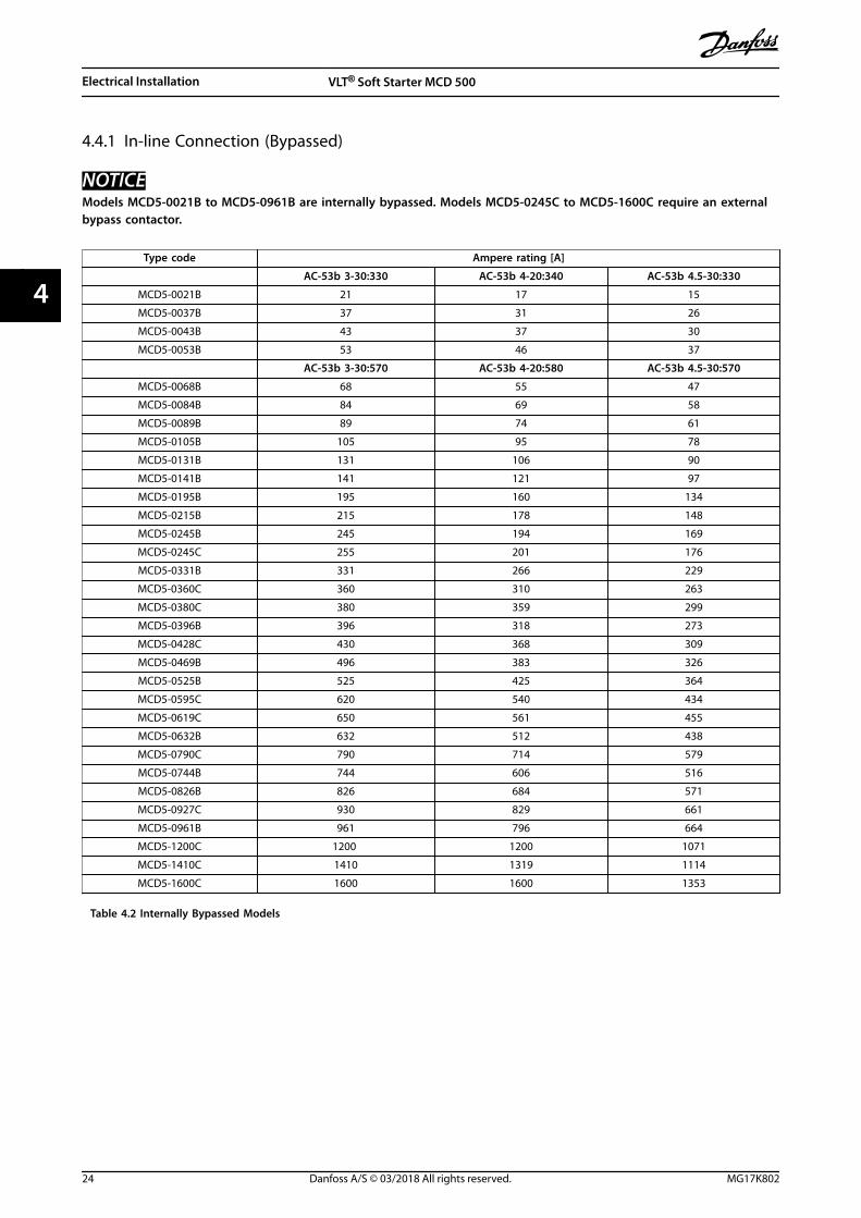
4.4.1 In-line Connection (Bypassed)
NOTICEModels MCD5-0021B to MCD5-0961B are internally bypassed. Models MCD5-0245C to MCD5-1600C require an externalbypass contactor.
Type code Ampere rating [A]
AC-53b 3-30:330 AC-53b 4-20:340 AC-53b 4.5-30:330
MCD5-0021B 21 17 15
MCD5-0037B 37 31 26
MCD5-0043B 43 37 30
MCD5-0053B 53 46 37
AC-53b 3-30:570 AC-53b 4-20:580 AC-53b 4.5-30:570
MCD5-0068B 68 55 47
MCD5-0084B 84 69 58
MCD5-0089B 89 74 61
MCD5-0105B 105 95 78
MCD5-0131B 131 106 90
MCD5-0141B 141 121 97
MCD5-0195B 195 160 134
MCD5-0215B 215 178 148
MCD5-0245B 245 194 169
MCD5-0245C 255 201 176
MCD5-0331B 331 266 229
MCD5-0360C 360 310 263
MCD5-0380C 380 359 299
MCD5-0396B 396 318 273
MCD5-0428C 430 368 309
MCD5-0469B 496 383 326
MCD5-0525B 525 425 364
MCD5-0595C 620 540 434
MCD5-0619C 650 561 455
MCD5-0632B 632 512 438
MCD5-0790C 790 714 579
MCD5-0744B 744 606 516
MCD5-0826B 826 684 571
MCD5-0927C 930 829 661
MCD5-0961B 961 796 664
MCD5-1200C 1200 1200 1071
MCD5-1410C 1410 1319 1114
MCD5-1600C 1600 1600 1353
Table 4.2 Internally Bypassed Models
Electrical Installation VLT® Soft Starter MCD 500
24 Danfoss A/S © 03/2018 All rights reserved. MG17K802
44

Illustration 4.17 AC-53 Rating for Bypassed Operation
All ratings are calculated at an altitude of 1000 m (3281 ft) and ambient temperature of 40 °C (104 °F).
4.4.2 In-line Connection (Non-bypassed/Continuous)
Type code Ampere ratings [A]
AC-53a 3-30:50-6 AC-53a 4-20:50-6 AC-53a 4.5-30:50-6
MCD5-0245C 245 195 171
MCD5-0360C 360 303 259
MCD5-0380C 380 348 292
MCD5-0428C 428 355 300
MCD5-0595C 595 515 419
MCD5-0619C 619 532 437
MCD5-0790C 790 694 567
MCD5-0927C 927 800 644
MCD5-1200C 1200 1135 983
MCD5-1410C 1410 1187 1023
MCD5-1600C 1600 1433 1227
Table 4.3 Non-bypassed Models
S t a r t T i m e ( s e c o n d s ) S t a r t s P e r H o u r
Illustration 4.18 AC-53 Rating for Continuous Operation
All ratings are calculated at an altitude of 1000 m (3281 ft) and ambient temperature of 40 °C (104 °F).
Contact a local supplier for ratings under operating conditions not covered by these ratings charts.
Electrical Installation Operating Guide
MG17K802 Danfoss A/S © 03/2018 All rights reserved. 25
4 4

4.4.3 Inside Delta Connection (Bypassed)
NOTICEModels MCD5-0021B to MCD5-0961B are internally bypassed. Models MCD5-0245C to MCD5-1600C require an externalbypass contactor.
Type code Ampere ratings [A]
AC-53b 3-30:330 AC-53b 4.20-:340 AC-53b 4.5-30:330
MCD5-0021B 32 26 22
MCD5-0037B 56 47 39
MCD5-0043B 65 56 45
MCD5-0053B 80 69 55
AC-53b 3-30:570 AC-53b 4-20:580 AC-53b 4.5-30:570
MCD5-0068B 102 83 71
MCD5-0084B 126 104 87
MCD5-0089B 134 112 92
MCD5-0105B 158 143 117
MCD5-0131B 197 159 136
MCD5-0141B 212 181 146
MCD5-0195B 293 241 201
MCD5-0215B 323 268 223
MCD5-0245B 368 291 254
MCD5-0245C 383 302 264
MCD5-0331B 497 400 343
MCD5-0360C 540 465 395
MCD5-0380C 570 539 449
MCD5-0396B 594 478 410
MCD5-0428C 645 552 463
MCD5-0469B 704 575 490
MCD5-0525B 787 637 546
MCD5-0595C 930 810 651
MCD5-0619C 975 842 683
MCD5-0632B 948 768 658
MCD5-0790C 1185 1072 869
MCD5-0744B 1116 910 774
MCD5-0826B 1239 1026 857
MCD5-0927C 1395 1244 992
MCD5-0961B 1441 1194 997
MCD5-1200C 1800 1800 1607
MCD5-1410C 2115 1979 1671
MCD5-1600C 2400 2400 2030
Table 4.4 Bypassed Models
Electrical Installation VLT® Soft Starter MCD 500
26 Danfoss A/S © 03/2018 All rights reserved. MG17K802
44

Illustration 4.19 AC-53 Rating for Bypassed Operation
All ratings are calculated at an altitude of 1000 m (3281 ft) and ambient temperature of 40 °C (104 °F).
4.4.4 Inside Delta Connection (Non-bypassed/Continuous)
Type code Ampere ratings [A]
AC-53a 3-30:50-6 AC-53a 4-20:50-6 AC-53a 4.5-30:50-6
MCD5-0245C 368 293 257
MCD5-0360C 540 455 389
MCD5-0380C 570 522 438
MCD5-0428C 643 533 451
MCD5-0595C 893 773 629
MCD5-0619C 929 798 656
MCD5-0790C 1185 1042 851
MCD5-0927C 1391 1200 966
MCD5-1200C 1800 1702 1474
MCD5-1410C 2115 1780 1535
MCD5-1600C 2400 2149 1841
Table 4.5 Non-bypassed Models
S t a r t T i m e ( s e c o n d s ) S t a r t s P e r H o u r
Illustration 4.20 AC-53 Rating for Continuous Operation
All ratings are calculated at an altitude of 1000 m (3281 ft) and ambient temperature of 40 °C (104 °F).
Contact a local supplier for ratings under operating conditions not covered by these ratings charts.
Electrical Installation Operating Guide
MG17K802 Danfoss A/S © 03/2018 All rights reserved. 27
4 4

4.5 Minimum and Maximum Current Settings
The minimum and maximum full load current settings depend on the model:
In-line connection Inside delta connection
Model Minimum [A] Maximum [A] Minimum [A] Maximum [A]
MCD5-0021B 5 23 7 34
MCD5-0037B 9 43 13 64
MCD5-0043B 10 50 15 75
MCD5-0053B 11 53 16 79
MCD5-0068B 15 76 23 114
MCD5-0084B 19 97 29 145
MCD5-0089B 20 100 30 150
MCD5-0105B 21 105 32 157
MCD5-0131B 29 145 44 217
MCD5-0141B 34 170 51 255
MCD5-0195B 40 200 60 300
MCD5-0215B 44 220 66 330
MCD5-0331B 70 350 70 525
MCD5-0396B 85 425 85 638
MCD5-0469B 100 500 100 750
MCD5-0525B 116 580 116 870
MCD5-0632B 140 700 140 1050
MCD5-0744B 164 820 164 1230
MCD5-0825B 184 920 184 1380
MCD5-0961B 200 1000 200 1500
MCD5-0245C 51 255 77 382
MCD5-0360C 72 360 108 540
MCD5-0380C 76 380 114 570
MCD5-0428C 86 430 129 645
MCD5-0595C 124 620 186 930
MCD5-0619C 130 650 195 975
MCD5-0790C 158 790 237 1185
MCD5-0927C 186 930 279 1395
MCD5-1200C 240 1200 360 1800
MCD5-1410C 282 1410 423 2115
MCD5-1600C 320 1600 480 2400
Table 4.6 Minimum and Maximum Full Load Current
4.6 Bypass Contactor
Some VLT® Soft Starters MCD 500 are internally bypassedand do not require an external bypass contactor.
Non-bypassed soft starters may be installed with anexternal bypass contactor. Select a contactor with an AC1rating greater than or equal to the full load current ratingof the connected motor.
4.7 Main Contactor
Install a main contactor if the VLT® Soft Starter MCD 500 isconnected to the motor in inside delta format and isoptional for in-line connection. Select a contactor with anAC3 rating greater than or equal to the full load currentrating of the connected motor.
4.8 Circuit Breaker
A shunt trip circuit breaker may be used instead of a maincontactor to isolate the motor circuit if a soft starter trips.The shunt trip mechanism must be powered from thesupply side of the circuit breaker or from a separatecontrol supply.
Electrical Installation VLT® Soft Starter MCD 500
28 Danfoss A/S © 03/2018 All rights reserved. MG17K802
44

4.9 Power Factor Correction
CAUTIONEQUIPMENT DAMAGEConnecting power factor correction capacitors to theoutput side damages the soft starter.
• Connect power factor correction capacitors tothe input side of the soft starter.
If power factor correction is used, use a dedicatedcontactor to switch in the capacitors.
4.10 Fuses
4.10.1 Power Supply Fuses
NOTICEWARRANTYTo keep the warranty on the SCRs, all fuses should besemiconductor fuses.
NOTICEUse semiconductor fuses for Type 2 coordination(according to the IEC 60947-4-2 standard) to preventdamaging the SCRs. VLT® Soft Starter MCD 500 hasintegrated SCR protection against overload transientcurrents, but if there is a short circuit (for example dueto a defective motor winding) this protection is notsufficient.
HRC fuses (such as Ferraz AJT fuses) can be used for Type1 coordination according to the IEC 60947-4-2 standard.
NOTICEAdaptive control regulates the speed profile of the motorwithin the programmed time limit. This control mayresult in a higher level of current than traditional controlmethods.
For applications using adaptive control to soft stop themotor with stop times greater than 30 s, select motorbranch protection as follows:
• Standard HRC mains fuses: Minimum 150% motorfull load current.
• Motor rated mains fuses: Minimum rating100/150% motor full load current.
• Motor control circuit breaker minimum long timesetting: 150% motor full load current.
• Motor control circuit breaker minimum short timesetting: 400% motor full load current for 30 s.
Fuse recommendations are calculated for 40 °C (104 °F),and at an altitude of up to 1000 m (3281 ft).
NOTICEFuse selection is based on a 400% FLC start for 20 swith:
• Standard published starts per hour.
• Duty cycle.
• 40 °C (104 °F) ambient temperature.
• Up to 1000 m (3281 ft) altitude.
For installations operating outside these conditions,consult a local Danfoss supplier.Table 4.7 to Table 4.13 contain recommendations only. Toconfirm the selection for a particular application, alwaysconsult a local supplier.
Electrical Installation Operating Guide
MG17K802 Danfoss A/S © 03/2018 All rights reserved. 29
4 4

4.10.2 Bussmann Fuses
Model SCR I2t (A2s) Supply voltage(≤440 V AC)
Supply voltage(≤575 V AC)
Supply voltage(≤690 V AC)
MCD5-0021B 1150 170M1314 170M1314 170M1314
MCD5-0037B 8000 170M1316 170M1316 170M1316
MCD5-0043B 10500 170M1318 170M1318 170M1318
MCD5-0053B 15000 170M1318 170M1318 170M1318
MCD5-0068B 15000 170M1319 170M1319 170M1318
MCD5-0084B 512000 170M1321 170M1321 170M1319
MCD5-0089B 80000 170M1321 170M1321 170M1321
MCD5-0105B 125000 170M1321 170M1321 170M1321
MCD5-0131B 125000 170M1321 170M1321 170M1321
MCD5-0141B 320000 170M2621 170M2621 170M2621
MCD5-0195B 320000 170M2621 170M2621 170M2621
MCD5-0215B 320000 170M2621 170M2621 170M2621
MCD5-0245B 320000 170M2621 170M2621 170M2621
MCD5-0331B 202000 170M5011 170M5011 –
MCD5-0396B 320000 170M6011 – –
MCD5-0469B 320000 170M60081) – –
MCD5-0525B 781000 170M6013 170M6013 170M6013
MCD5-0632B 781000 170M5015 170M5015 –
MCD5-0744B 1200000 170M5017 170M6017 –
MCD5-0826B 2530000 170M6017 170M6017 –
MCD5-0961B 2530000 170M6018 170M60131) –
MCD5-0245C 320000 170M2621 170M2621 170M2621
MCD5-0360C 320000 170M6010 170M6010 170M6010
MCD5-0380C 320000 170M6011 170M6011 –
MCD5-0428C 320000 170M6011 170M6011 –
MCD5-0595C 1200000 170M6015 170M6015 170M6014
MCD5-0619C 1200000 170M6015 170M6015 170M6014
MCD5-0790C 2530000 170M6017 170M6017 170M6016
MCD5-0927C 4500000 170M6019 170M6019 170M6019
MCD5-1200C 4500000 170M6021 – –
MCD5-1410C 6480000 – – –
MCD5-1600C 12500000 170M60191) – –
Table 4.7 Square Body (170M)
1) Two fuses connected in parallel are required per phase.
Electrical Installation VLT® Soft Starter MCD 500
30 Danfoss A/S © 03/2018 All rights reserved. MG17K802
44

Model SCR I2t (A2s) Supply voltage(<440 V AC)
Supply voltage(<575 V AC)
Supply voltage(<690 V AC)
MCD5-0021B 1150 63FE 63FE 63FE
MCD5-0037B 8000 120FEE 120FEE 120FEE
MCD5-0043B 10500 120FEE 120FEE 120FEE
MCD5-0053B 15000 200FEE 200FEE 200FEE
MCD5-0068B 15000 200FEE 200FEE 200FEE
MCD5-0084B 512000 200FEE 200FEE 200FEE
MCD5-0089B 80000 280FM 280FM 280FM
MCD5-0105B 125000 280FM 280FM 280FM
MCD5-0131B 125000 280FM 280FM 280FM
MCD5-0141B 320000 450FMM 450FMM 450FMM
MCD5-0195B 320000 450FMM 450FMM 450FMM
MCD5-0215B 320000 450FMM 450FMM 450FMM
MCD5-0245B 320000 450FMM 450FMM 450FMM
MCD5-0331B 202000 315FM1) – –
MCD5-0396B 320000 400FMM1) – –
MCD5-0469B 320000 450FMM1) – –
MCD5-0525B 781000 500FMM1) 500FMM1) 500FMM1)
MCD5-0632B 781000 630FMM1) – –
MCD5-0744B 1200000 – – –
MCD5-0826B 2530000 – – –
MCD5-0961B 2530000 – – –
MCD5-0245C 320000 450FMM 450FMM 450FMM
MCD5-0360C 320000 – – –
MCD5-0380C 320000 400FMM1) 400FMM 400FMM1)
MCD5-0428C 320000 – – –
MCD5-0595C 1200000 630FMM1) 630FMM1) –
MCD5-0619C 1200000 630FMM1) 630FMM1) –
MCD5-0790C 2530000 – – –
MCD5-0927C 4500000 – – –
MCD5-1200C 4500000 – – –
MCD5-1410C 6480000 – – –
MCD5-1600C 12500000 – – –
Table 4.8 British Style (BS88)
1) Two fuses connected in parallel are required per phase.
Electrical Installation Operating Guide
MG17K802 Danfoss A/S © 03/2018 All rights reserved. 31
4 4
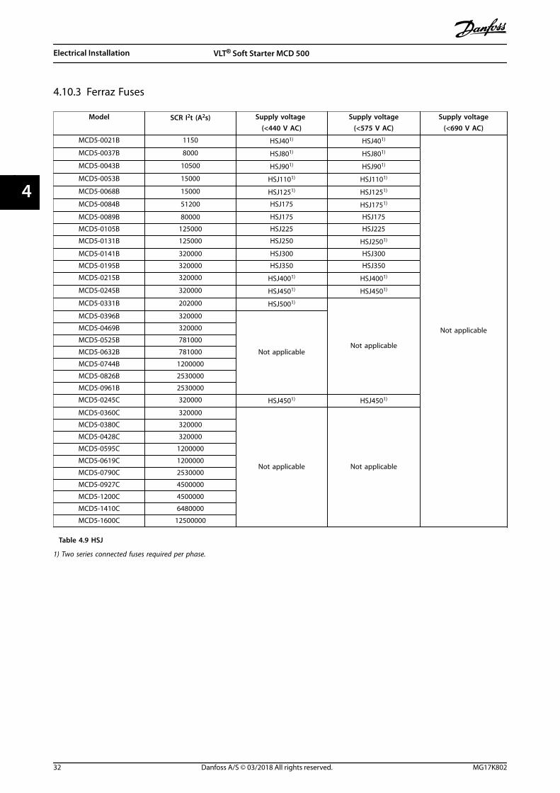
4.10.3 Ferraz Fuses
Model SCR I2t (A2s) Supply voltage (<440 V AC)
Supply voltage(<575 V AC)
Supply voltage(<690 V AC)
MCD5-0021B 1150 HSJ401) HSJ401)
Not applicable
MCD5-0037B 8000 HSJ801) HSJ801)
MCD5-0043B 10500 HSJ901) HSJ901)
MCD5-0053B 15000 HSJ1101) HSJ1101)
MCD5-0068B 15000 HSJ1251) HSJ1251)
MCD5-0084B 51200 HSJ175 HSJ1751)
MCD5-0089B 80000 HSJ175 HSJ175
MCD5-0105B 125000 HSJ225 HSJ225
MCD5-0131B 125000 HSJ250 HSJ2501)
MCD5-0141B 320000 HSJ300 HSJ300
MCD5-0195B 320000 HSJ350 HSJ350
MCD5-0215B 320000 HSJ4001) HSJ4001)
MCD5-0245B 320000 HSJ4501) HSJ4501)
MCD5-0331B 202000 HSJ5001)
Not applicable
MCD5-0396B 320000
Not applicable
MCD5-0469B 320000
MCD5-0525B 781000
MCD5-0632B 781000
MCD5-0744B 1200000
MCD5-0826B 2530000
MCD5-0961B 2530000
MCD5-0245C 320000 HSJ4501) HSJ4501)
MCD5-0360C 320000
Not applicable Not applicable
MCD5-0380C 320000
MCD5-0428C 320000
MCD5-0595C 1200000
MCD5-0619C 1200000
MCD5-0790C 2530000
MCD5-0927C 4500000
MCD5-1200C 4500000
MCD5-1410C 6480000
MCD5-1600C 12500000
Table 4.9 HSJ
1) Two series connected fuses required per phase.
Electrical Installation VLT® Soft Starter MCD 500
32 Danfoss A/S © 03/2018 All rights reserved. MG17K802
44
Model SCR I2t (A2s) Supply voltage (<440 V AC)
Supply voltage(<575 V AC)
Supply voltage(<690 V AC)
MCD5-0021B 1150 A070URD30XXX0063 A070URD30XXX0063 –
MCD5-0037B 8000 A070URD30XXX0125 A070URD30XXX0125 A070URD30XXX0125
MCD5-0043B 10500 A070URD30XXX0125 A070URD30XXX0125 A070URD30XXX0125
MCD5-0053B 15000 A070URD30XXX0125 A070URD30XXX0125 A070URD30XXX0125
MCD5-0068B 15000 A070URD30XXX0160 A070URD30XXX0160 A070URD30XXX0160
MCD5-0084B 51200 A070URD30XXX0200 A070URD30XXX0200 A070URD30XXX0200
MCD5-0089B 80000 A070URD30XXX0200 A070URD30XXX0200 A070URD30XXX0200
MCD5-0105B 125000 A070URD30XXX0315 A070URD30XXX0315 A070URD30XXX0315
MCD5-0131B 125000 A070URD30XXX0315 A070URD30XXX0315 A070URD30XXX0315
MCD5-0141B 320000 A070URD30XXX0315 A070URD30XXX0315 A070URD30XXX0315
MCD5-0195B 320000 A070URD30XXX0450 A070URD30XXX0450 A070URD30XXX0450
MCD5-0215B 320000 A070URD30XXX0450 A070URD30XXX0450 A070URD30XXX0450
MCD5-0245B 32000 A070URD30XXX0450 A070URD30XXX0450 A070URD30XXX0450
MCD5-0331B 202000 A070URD31XXX0550 – –
MCD5-0396B 238000 A070URD32XXX0630 – –
MCD5-0469B 320000 A070URD32XXX0700 – –
MCD5-0525B 781000 A070URD32XXX0800 – –
MCD5-0632B 781000 A070URD33XXX0900 – –
MCD5-0744B 1200000 A070URD33XXX1100 – –
MCD5-0826B 2530000 A070URD33XXX1250 – –
MCD5-0961B 2530000 A070URD33XXX1400 – –
MCD5-0245C 320000 A070URD30XXX0450 A070URD30XXX0450 A070URD30XXX0450
MCD5-0360C 320000 A070URD33XXX0630 A070URD33XXX0630 A070URD33XXX0630
MCD5-0380C 320000 A070URD33XXX0700 A070URD33XXX0700 –
MCD5-0428C 320000 A070URD33XXX0700 A070URD33XXX0700 –
MCD5-0595C 1200000 A070URD33XXX1000 A070URD33XXX1000 A070URD33XXX1000
MCD5-0619C 1200000 A070URD33XXX1000 A070URD33XXX1000 A070URD33XXX1000
MCD5-0790C 2530000 A070URD33XXX1400 A070URD33XXX1400 A070URD33XXX1400
MCD5-0927C 4500000 A070URD33XXX1400 A070URD33XXX1400 A070URD33XXX1400
MCD5-1200C 4500000 A055URD33XXX2250 – –
MCD5-1410C 6480000 A055URD33XXX2250 – –
MCD5-1600C 12500000 - – –
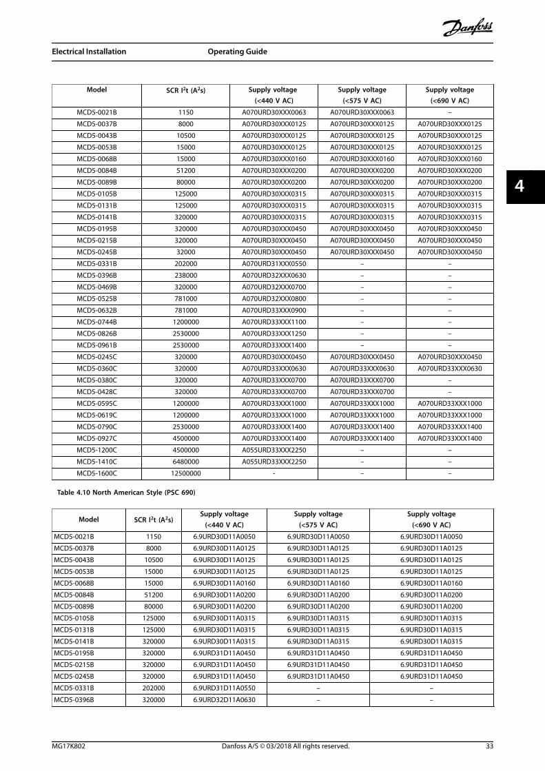
Table 4.10 North American Style (PSC 690)
Model SCR I2t (A2s)Supply voltage
(<440 V AC)Supply voltage
(<575 V AC)Supply voltage
(<690 V AC)
MCD5-0021B 1150 6.9URD30D11A0050 6.9URD30D11A0050 6.9URD30D11A0050
MCD5-0037B 8000 6.9URD30D11A0125 6.9URD30D11A0125 6.9URD30D11A0125
MCD5-0043B 10500 6.9URD30D11A0125 6.9URD30D11A0125 6.9URD30D11A0125
MCD5-0053B 15000 6.9URD30D11A0125 6.9URD30D11A0125 6.9URD30D11A0125
MCD5-0068B 15000 6.9URD30D11A0160 6.9URD30D11A0160 6.9URD30D11A0160
MCD5-0084B 51200 6.9URD30D11A0200 6.9URD30D11A0200 6.9URD30D11A0200
MCD5-0089B 80000 6.9URD30D11A0200 6.9URD30D11A0200 6.9URD30D11A0200
MCD5-0105B 125000 6.9URD30D11A0315 6.9URD30D11A0315 6.9URD30D11A0315
MCD5-0131B 125000 6.9URD30D11A0315 6.9URD30D11A0315 6.9URD30D11A0315
MCD5-0141B 320000 6.9URD30D11A0315 6.9URD30D11A0315 6.9URD30D11A0315
MCD5-0195B 320000 6.9URD31D11A0450 6.9URD31D11A0450 6.9URD31D11A0450
MCD5-0215B 320000 6.9URD31D11A0450 6.9URD31D11A0450 6.9URD31D11A0450
MCD5-0245B 320000 6.9URD31D11A0450 6.9URD31D11A0450 6.9URD31D11A0450
MCD5-0331B 202000 6.9URD31D11A0550 – –
MCD5-0396B 320000 6.9URD32D11A0630 – –
Electrical Installation Operating Guide
MG17K802 Danfoss A/S © 03/2018 All rights reserved. 33
4 4

Model SCR I2t (A2s)Supply voltage
(<440 V AC)Supply voltage
(<575 V AC)Supply voltage
(<690 V AC)
MCD5-0469B 320000 6.9URD32D11A0700 – –
MCD5-0525B 781000 6.9URD32D11A0800 – –
MCD5-0632B 781000 6.9URD33D11A0900 – –
MCD5-0744B 1200000 6.9URD33D11A1100 – –
MCD5-0826B 2530000 6.9URD33D11A1250 – –
MCD5-0961B 2530000 6.9URD33D11A1400 – –
MCD5-0245C 320000 6.9URD31D11A0450 6.9URD31D11A0450 6.9URD31D11A0450
MCD5-0360C 320000 6.9URD33D11A0630 6.9URD33D11A0630 6.9URD33D11A0630
MCD5-0380C 320000 6.9URD33D11A0700 6.9URD33D11A0700 6.9URD33D11A0700
MCD5-0428C 320000 6.9URD33D11A0700 6.9URD33D11A0700 6.9URD33D11A0700
MCD5-0595C 1200000 6.9URD33D11A1000 6.9URD33D11A1000 6.9URD33D11A1000
MCD5-0619C 1200000 6.9URD33D11A1000 6.9URD33D11A1000 6.9URD33D11A1000
MCD5-0790C 2530000 6.6URD33D11A1400 6.6URD33D11A1400 –
MCD5-0927C 4500000 6.6URD33D11A1400 6.6URD33D11A1400 –
MCD5-1200C 4500000 6URD233PLAF2200 6URD233PLAF2200 –
MCD5-1410C 6480000 6URD233PLAF2200 6URD233PLAF2200 –
MCD5-1600C 12500000 6URD233PLAF2800 6URD233PLAF2800 –
Table 4.11 European Style (PSC 690)
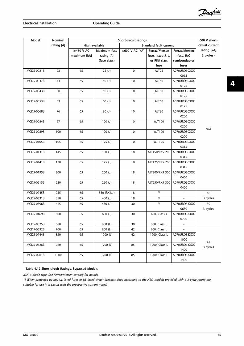
4.10.4 UL Fuse Selection and Short Circuit Ratings
Two short-circuit current ratings (SCCR) are available for UL-compliant applications.
Standard fault currents (@600 V AC circuits)The standard fault currents are determined referring to UL 508, section 1, table 51.2. This standard specifies the short-circuitcurrent that the soft starter must withstand based on the horse power rating (or full load current (FLC) rating, or lockedrotor amps (LRA) depending on the model).
If using the standard fault current ratings, the fuse must be in accordance with the information in Table 4.12 (model- andmanufacturer-specific).
High available fault currents (@480 V AC circuits)It is possible to specify short-circuit current ratings exceeding the minimum ratings set by the standard fault currents whenthe soft starter is able to withstand the high available short-circuit current in accordance with the UL 508 test.
If using the high available fault current ratings, select a suitable fuse based on amperage and fuse class (J or L asapplicable).
Electrical Installation VLT® Soft Starter MCD 500
34 Danfoss A/S © 03/2018 All rights reserved. MG17K802
44
Model Nominalrating [A]
Short-circuit ratings 600 V short-circuit current
rating [kA]
3 cycles1)
High available Standard fault current
@480 V ACmaximum [kA]
Maximum fuserating [A]
(fuse class)
@600 V AC [kA] Ferraz/Mersenfuse, listed J, L,
or RK5 classfuse
Ferraz/Mersenfuse, R/C
semiconductorfuses
MCD5-0021B 23 65 25 (J) 10 AJT25 A070URD30XXX0063
N/A
MCD5-0037B 43 65 50 (J) 10 AJT50 A070URD30XXX0125
MCD5-0043B 50 65 50 (J) 10 AJT50 A070URD30XXX0125
MCD5-0053B 53 65 60 (J) 10 AJT60 A070URD30XXX0125
MCD5-0068B 76 65 80 (J) 10 AJT80 A070URD30XXX0200
MCD5-0084B 97 65 100 (J) 10 AJT100 A070URD30XXX0200
MCD5-0089B 100 65 100 (J) 10 AJT100 A070URD30XXX0200
MCD5-0105B 105 65 125 (J) 10 AJT125 A070URD30XXX0315
MCD5-0131B 145 65 150 (J) 18 AJT150/RK5 200 A070URD30XXX0315
MCD5-0141B 170 65 175 (J) 18 AJT175/RK5 200 A070URD30XXX0315
MCD5-0195B 200 65 200 (J) 18 AJT200/RK5 300 A070URD30XXX0450
MCD5-0215B 220 65 250 (J) 18 AJT250/RK5 300 A070URD30XXX0450
MCD5-0245B 255 65 350 (RK1/J) 18 1) – 183 cyclesMCD5-0331B 350 65 400 (J) 18 1) –
MCD5-0396B 425 65 450 (J) 30 1) A070URD33XXX0630
303 cycles
MCD5-0469B 500 65 600 (J) 30 600, Class J A070URD33XXX0700
MCD5-0525B 580 65 800 (L) 30 800, Class L –
MCD5-0632B 700 65 800 (L) 42 800, Class L –
423 cycles
MCD5-0744B 820 65 1200 (L) 42 1200, Class L A070URD33XXX1000
MCD5-0826B 920 65 1200 (L) 85 1200, Class L A070URD33XXX1400
MCD5-0961B 1000 65 1200 (L) 85 1200, Class L A070URD33XXX1400
Table 4.12 Short-circuit Ratings, Bypassed Models
XXX = blade type: See Ferraz/Mersen catalog for details.1) When protected by any UL listed fuses or UL listed circuit breakers sized according to the NEC, models provided with a 3-cycle rating aresuitable for use in a circuit with the prospective current noted.
Electrical Installation Operating Guide
MG17K802 Danfoss A/S © 03/2018 All rights reserved. 35
4 4

Model Nominalrating [A]
Short-circuit ratings 600 V short-circuit current
rating [kA]
3 cycles1)
High available Standard fault current
@480 V ACmaximum [kA]
Maximum fuserating [A]
(fuse class)
@600 V AC [kA] Ferraz/Mersenfuse, listed J, L,
or RK5 classfuse
Ferraz/Mersenfuse, R/C
semiconductorfuses
MCD5-0245C 255 65 350 (RK1/J) 18 AJT300 A070URD30XXX0450
N/A
MCD5-0360C 360 65 400 (J) 18 AJT400/RK5 500 A070URD33XXX0630
MCD5-0380C 380 65 450 (J) 18 AJT450/RK5 500 A070URD33XXX0700
MCD5-0428C 430 65 450 (J) 30 AJT450 A070URD33XXX0700
MCD5-0595C 620 65 800 (L) 42 A4BQ800 A070URD33XXX1000
MCD5-0619C 650 65 800 (L) 42 A4BQ800 A070URD33XXX1000
MCD5-0790C 790 65 1200 (L) 42 A4BQ1200 070URD33XXX1400
MCD5-0927C 930 65 1200 (L) 42 A4BQ1200 A070URD33XXX1400
MCD5-1200C 1200 65 1600 (L) 85 A4BQ1600 A065URD33XXX1800
MCD5-1410C 1410 65 2000 (L) 85 A4BQ2000 A055URD33XXX2250
MCD5-1600C 1600 65 2000 (L) 85 A4BQ2500 A055URD33XXX2500
Table 4.13 Short-circuit Ratings, Non-bypassed Models
XXX = blade type: See Ferraz/Mersen catalog for details.1) When protected by any UL listed fuses or UL listed circuit breakers sized according to the NEC, models provided with a 3-cycle rating aresuitable for use in a circuit with the prospective current noted.
Electrical Installation VLT® Soft Starter MCD 500
36 Danfoss A/S © 03/2018 All rights reserved. MG17K802
44

4.11 Schematic Diagrams
22
21
6/T3
2/T1
13
14
4/T2
24
33
34
06
05
08
07
17
18
25
11
16
A6
A5
A4
5/L3
3/L2
15
E
1/L1
+
24 V DC
5
4
2A
3
1
177H
A42
5.10
1 Control supply (model dependent) 11, 16 Programmable input
2 Outputs 15, 16 Start
3 Remote control inputs 17, 18 Stop
4 Motor thermistor input (PTC only) 25, 18 Reset
5 Relay outputs 13, 14 Relay output A
07, 08 Programmable analog output 21, 22, 24 Relay output B
16, 08 24 V DC output 33, 34 Relay output C
Illustration 4.21 Internally Bypassed Models
Electrical Installation Operating Guide
MG17K802 Danfoss A/S © 03/2018 All rights reserved. 37
4 4

177H
A42
6.12
E
6/T3
2/T1
4/T2
5/L3
3/L2
1/L1
L3B
L2B
L1B
22
21
13
1)
1)
1)
14
24
33
34
06
05
08
07
17
18
25
11
16
A6
A5
A4
15
+
+ 5
4
2A
3
1
24 V DC
1 Control supply (model dependent) 11, 16 Programmable input
2 Outputs 15, 16 Start
3 Remote control inputs 17, 18 Stop
4 Motor thermistor input (PTC only) 25, 18 Reset
5 Relay outputs 13, 14 Relay output A
07, 08 Programmable analog output 21, 22, 24 Relay output B
16, 08 24 V DC output 33, 34 Relay output C
Illustration 4.22 Non-bypassed Models
1) MCD5-0245C current transformers are placed on the output. Bypass terminals are labeled T1B, T2B, and T3B.
Electrical Installation VLT® Soft Starter MCD 500
38 Danfoss A/S © 03/2018 All rights reserved. MG17K802
44

5 Product Features
5.1 Motor Overload Protection
The thermal model used for motor overload in the softstarter has 2 components:
• Motor windings: The motor windings have a lowthermal capacity and affect the short-termthermal behavior of the motor. The motorwindings are where the current generates heat.
• Motor body: The motor body has a large thermalcapacity and affects the long-term behavior ofthe motor. The thermal model includes consider-ations for the following:
- Motor current.
- Iron losses.
- Winding resistance losses.
- Motor body and winding thermalcapacities.
- Cooling during run and cooling atstandstill.
- The percentage of the rated capacity ofthe motor. This sets the shown value forthe winding model and is affected bythe motor FLC setting among others.
NOTICESet parameter 1-1 Motor FLC to the rated motor FLC. Donot add the overload rating as the soft starter calculatesthis rating.
The thermal overload protection used in the soft starterhas several advantages over the thermal relays.
• The effect of fan cooling is accounted for whenthe motor is running.
• The actual full load current and locked rotor timecan be used to tune the model more accurately.The thermal characteristics of the windings aretreated separately from the rest of the motor(that is the model recognizes that the windingshave low thermal mass and high thermalresistance).
• The winding portion of the thermal modelresponds rapidly compared with the bodyportion. Thus, the motor can be run closer to itssafe maximum operating temperature while stillbeing protected from thermal damage.
• The percentage of motor thermal capacity usedduring each start is stored in memory. The softstarter can be configured to determine automat-ically whether the motor has sufficient thermal
capacity remaining to complete another startsuccessfully.
• The memory function of the model ensures thatthe motor is fully protected in warm-startsituations. The model uses data from the real-time clock to account for elapsed cooling time,even if control power has been removed.
The overload protection function provided by this model iscompliant with a NEMA 10 curve, but provides superiorprotection at low levels of overload due to the separationof the winding thermal model.
100 200 3001
10
100
1000
10000
177H
A59
6.10
Tim
e in
sec
onds
to re
ach
100%
of
ther
mal
mod
el
Current (%motor full load current)
3
1
2
400 500 600 700 800 900 1000
1 MSTC1)=5
2 MSTC1)=10
3 MSTC1)=20
1) MSTC is the motor start time constant. It is defined as the lockedrotor time (in parameter 1-2 Locked Rotor Time) when the lockedrotor current is 600% of FLC.
Illustration 5.1 Protection Degree Compared to Overload
5.2 Adaptive Control
Adaptive control is motor control based on theperformance characteristics of the motor. With adaptivecontrol, select the starting or stopping profile that bestmatches the load type. The soft starter automaticallycontrols the motor to match the profile. The VLT® SoftStarter MCD 500 offers 3 profiles:
Product Features Operating Guide
MG17K802 Danfoss A/S © 03/2018 All rights reserved. 39
5 5
• Early acceleration and deceleration.
• Constant acceleration and deceleration.
• Late acceleration and deceleration.
Adaptive control uses 2 algorithms; 1 to measure themotor characteristics, and 1 to control the motor. The softstarter uses the first start to determine the motor charac-teristics at 0 speed and at maximum speed. During eachsubsequent start and stop, the soft starter dynamicallyadjusts its control to ensure that the actual motorperformance matches the selected profile throughout thestart. If the actual speed is too low for the profile, the softstarter increases power to the motor. If the speed is toohigh, the soft starter decreases power.
5.3 Starting Modes
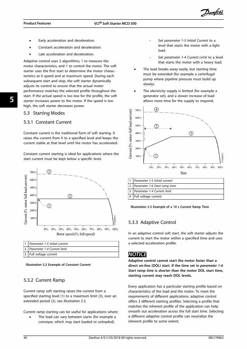
5.3.1 Constant Current
Constant current is the traditional form of soft starting. Itraises the current from 0 to a specified level and keeps thecurrent stable at that level until the motor has accelerated.
Constant current starting is ideal for applications where thestart current must be kept below a specific level.
7 0 0 %
6 0 0 %
5 0 0 %
3 0 0 %
1 0 0 %
4 0 0 %
2 0 0 %
1 0 % 2 0 % 3 0 % 4 0 % 5 0 %
R o t o r s p e e d ( % f u l l s p e e d ) 6 0 % 7 0 % 8 0 % 9 0 % 1 0 0 %
1 7 7 H
A 2 8
9 . 1 1
C u r
r e n t
( % m
o t o r
f u l l
l o a d
c u r r
e n t )
1
3
2
1 Parameter 1-5 Initial current
2 Parameter 1-4 Current limit
3 Full voltage current
Illustration 5.2 Example of Constant Current
5.3.2 Current Ramp
Current ramp soft starting raises the current from aspecified starting level (1) to a maximum limit (3), over anextended period (2), see Illustration 5.3.
Current ramp starting can be useful for applications where:• The load can vary between starts (for example a
conveyor, which may start loaded or unloaded).
- Set parameter 1-5 Initial Current to alevel that starts the motor with a lightload.
- Set parameter 1-4 Current Limit to a levelthat starts the motor with a heavy load.
• The load breaks away easily, but starting timemust be extended (for example a centrifugalpump where pipeline pressure must build upslowly).
• The electricity supply is limited (for example agenerator set), and a slower increase of loadallows more time for the supply to respond.
7 0 0 %
6 0 0 %
5 0 0 %
3 0 0 %
1 0 0 %
4 0 0 %
2 0 0 %
1 0 % 2 0 % 3 0 % 4 0 % 5 0 % 6 0 % 7 0 % 8 0 % 9 0 % 1 0 0 %
T i m e
1 7 7 H
A 2 8
9 . 1 1
C u r
r e n t
( % m
o t o r
f u l l
l o a d
c u r r
e n t )
3
1
2
4
1 Parameter 1-5 Initial current
2 Parameter 1-6 Start ramp time
3 Parameter 1-4 Current limit
4 Full voltage current
Illustration 5.3 Example of a 10 s Current Ramp Time
5.3.3 Adaptive Control
In an adaptive control soft start, the soft starter adjusts thecurrent to start the motor within a specified time and usesa selected acceleration profile.
NOTICEAdaptive control cannot start the motor faster than adirect on-line (DOL) start. If the time set in parameter 1-6Start ramp time is shorter than the motor DOL start time,starting current may reach DOL levels.
Every application has a particular starting profile based oncharacteristics of the load and the motor. To meet therequirements of different applications, adaptive controloffers 3 different starting profiles. Selecting a profile thatmatches the inherent profile of the application can helpsmooth out acceleration across the full start time. Selectinga different adaptive control profile can neutralize theinherent profile to some extent.
Product Features VLT® Soft Starter MCD 500
40 Danfoss A/S © 03/2018 All rights reserved. MG17K802
55
To use adaptive control to control starting performance:1. Select Adaptive control in parameter 1-3 Start
Mode.
2. Set parameter 1-6 Start Ramp Time.
3. Select the wanted profile in parameter 1-13Adaptive Start Profile.
4. Set parameter 1-4 Current Limit sufficiently high toallow a successful start.
The 1st adaptive control start is a constant current start.This start type allows the soft starter to learn the charac-teristics of the connected motor. The soft starter uses thismotor data during subsequent adaptive control starts.
0
1 0 %
2 0 %
3 0 %
4 0 %
5 0 %
T i m e
6 0 %
7 0 %
8 0 %
9 0 %
1 0 0 %
4 1 7
7 H A
5 0 7 . 1
0
S p e e
d 1
2
3
1 Early acceleration
2 Constant acceleration
3 Late acceleration
4 Parameter 1-16 Start Ramp Time
Illustration 5.4 Parameter 1-13 Adaptive Start Profile
NOTICEAdaptive control regulates the load according to theprogrammed profile. Start current varies according to theselected acceleration profile and the programmed starttime.The soft starter has to learn the characteristics of a newmotor:
• If replacing a motor connected to a soft starterprogrammed for adaptive control starting orstopping.
• If the soft starter has been tested on a differentmotor before actual installation.
If parameter 1-1 Motor Full Load Current or parameter1-12 Adaptive Control Gain is changed, the soft starterautomatically relearns the motor characteristics.
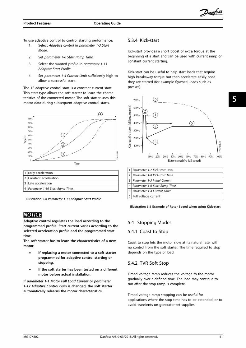
5.3.4 Kick-start
Kick-start provides a short boost of extra torque at thebeginning of a start and can be used with current ramp orconstant current starting.
Kick-start can be useful to help start loads that requirehigh breakaway torque but then accelerate easily oncethey are started (for example flywheel loads such aspresses).
7 0 0 %
6 0 0 %
5 0 0 %
3 0 0 %
1 0 0 %
4 0 0 %
2 0 0 %
1 0 % 2 0 % 3 0 % 4 0 % 5 0 % R o t o r s p e e d ( % f u l l s p e e d )
6 0 % 7 0 % 8 0 % 9 0 % 1 0 0 %
1 7 7 H
A 5 0
8 . 1 0
C u r
r e n t
( % m
o t o r
f u l l
l o a d
c u r r
e n t )
1
5 4
6
3
2
1 Parameter 1-7 Kick-start Level
2 Parameter 1-8 Kick-start Time
3 Parameter 1-5 Initial Current
4 Parameter 1-6 Start Ramp Time
5 Parameter 1-4 Current Limit
6 Full voltage current
Illustration 5.5 Example of Rotor Speed when using Kick-start
5.4 Stopping Modes
5.4.1 Coast to Stop
Coast to stop lets the motor slow at its natural rate, withno control from the soft starter. The time required to stopdepends on the type of load.
5.4.2 TVR Soft Stop
Timed voltage ramp reduces the voltage to the motorgradually over a defined time. The load may continue torun after the stop ramp is complete.
Timed voltage ramp stopping can be useful forapplications where the stop time has to be extended, or toavoid transients on generator-set supplies.
Product Features Operating Guide
MG17K802 Danfoss A/S © 03/2018 All rights reserved. 41
5 5

7 0 %
6 0 %
5 0 %
3 0 %
1 0 %
4 0 %
T i m e
V o l t a
g e ( %
f u l l
v o l t a
g e )
2 0 %
8 0 %
9 0 %
1 0 0 %
1 7 7 H A 5 0 9 . 1 0
1
1 Parameter 1-11 Stop Time
Illustration 5.6 TVR Soft Stop
5.4.3 Adaptive Control
To use adaptive control to control stopping performance:1. Select Adaptive control from the Stop Mode menu.
2. Set parameter 1-11 Stop Time.
3. Select the required profile in parameter 1-14Adaptive Stop Profile.
0 1 0 %
2 0 %
3 0 %
4 0 %
5 0 %
T i m e
S p e e
d 6 0 %
7 0 %
8 0 %
9 0 %
1 0 0 %
1 7 7 H
A 5 1
0 . 1 0
1 2
4
3
1 Early deceleration
2 Constant deceleration
3 Late deceleration
4 Parameter 1-10 Stop Time
Illustration 5.7 Parameter 1-14 Adaptive Stop Profile
NOTICEAdaptive control does not actively slow the motor downand does not stop the motor faster than a coast to stop.To shorten the stopping time of high-inertia loads, use abrake function, see chapter 5.4.5 Brake.
The first adaptive control stop is a normal soft stop. Thisstop type allows the soft starter to learn the characteristics
of the connected motor. The soft starter uses this motordata during subsequent adaptive control stops.
NOTICEAdaptive control regulates the load according to theprogrammed profile. Stopping current varies accordingto the selected deceleration profile and stop time.
The soft starter has to learn the characteristics of a newmotor:
• If replacing a motor connected to a soft starterprogrammed for adaptive control starting orstopping.
• If the soft starter has been tested on a differentmotor before actual installation.
If parameter 1-1 Motor Full Load Current or parameter1-12 Adaptive Control Gain is changed, the soft starterautomatically relearns the motor characteristics.
5.4.4 Pump Stopping
The hydraulic characteristics of pump systems vary consid-erably. This variation means that the ideal decelerationprofile and stop time vary from application to application.Table 5.1 provides guidelines on selecting betweenadaptive control profiles. For identification of the bestprofile for the application, test all 3 profiles.
Adaptive stopprofile
Application
Late deceleration High-head systems, where even a smalldecrease in motor/pump speed results in arapid transition between forward flow andreverse flow.
Constantdeceleration
Low to medium head, high-flowapplications, where the fluid has highmomentum.
Early deceleration Open pump systems, where fluid must drainback through the pump without driving thepump in reverse.
Table 5.1 Selection of Adaptive Control Deceleration Profiles
5.4.5 Brake
A brake reduces the required stop time of the motor.
During braking, an increased noise level from the motormay be audible. This noise is a normal part of motorbraking.
Product Features VLT® Soft Starter MCD 500
42 Danfoss A/S © 03/2018 All rights reserved. MG17K802
55
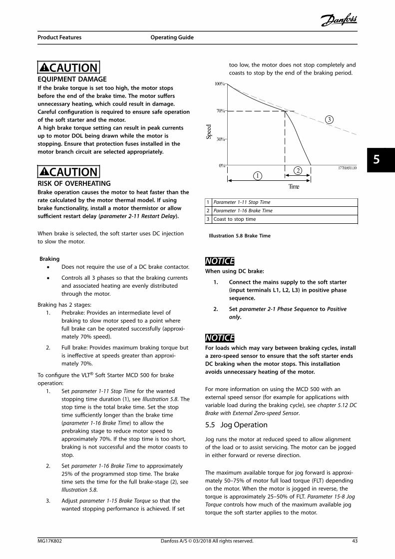
CAUTIONEQUIPMENT DAMAGEIf the brake torque is set too high, the motor stopsbefore the end of the brake time. The motor suffersunnecessary heating, which could result in damage.Careful configuration is required to ensure safe operationof the soft starter and the motor.A high brake torque setting can result in peak currentsup to motor DOL being drawn while the motor isstopping. Ensure that protection fuses installed in themotor branch circuit are selected appropriately.
CAUTIONRISK OF OVERHEATINGBrake operation causes the motor to heat faster than therate calculated by the motor thermal model. If usingbrake functionality, install a motor thermistor or allowsufficient restart delay (parameter 2-11 Restart Delay).
When brake is selected, the soft starter uses DC injectionto slow the motor.
Braking• Does not require the use of a DC brake contactor.
• Controls all 3 phases so that the braking currentsand associated heating are evenly distributedthrough the motor.
Braking has 2 stages:1. Prebrake: Provides an intermediate level of
braking to slow motor speed to a point wherefull brake can be operated successfully (approxi-mately 70% speed).
2. Full brake: Provides maximum braking torque butis ineffective at speeds greater than approxi-mately 70%.
To configure the VLT® Soft Starter MCD 500 for brakeoperation:
1. Set parameter 1-11 Stop Time for the wantedstopping time duration (1), see Illustration 5.8. Thestop time is the total brake time. Set the stoptime sufficiently longer than the brake time(parameter 1-16 Brake Time) to allow theprebraking stage to reduce motor speed toapproximately 70%. If the stop time is too short,braking is not successful and the motor coasts tostop.
2. Set parameter 1-16 Brake Time to approximately25% of the programmed stop time. The braketime sets the time for the full brake-stage (2), seeIllustration 5.8.
3. Adjust parameter 1-15 Brake Torque so that thewanted stopping performance is achieved. If set
too low, the motor does not stop completely andcoasts to stop by the end of the braking period.
1 0 0 %
7 0 %
0 %
3 0 %
1 2
3
1 7 7 H A 5 1 1 . 1 0
T i m e
S p e e
d 1 Parameter 1-11 Stop Time
2 Parameter 1-16 Brake Time
3 Coast to stop time
Illustration 5.8 Brake Time
NOTICEWhen using DC brake:
1. Connect the mains supply to the soft starter(input terminals L1, L2, L3) in positive phasesequence.
2. Set parameter 2-1 Phase Sequence to Positiveonly.
NOTICEFor loads which may vary between braking cycles, installa zero-speed sensor to ensure that the soft starter endsDC braking when the motor stops. This installationavoids unnecessary heating of the motor.
For more information on using the MCD 500 with anexternal speed sensor (for example for applications withvariable load during the braking cycle), see chapter 5.12 DCBrake with External Zero-speed Sensor.
5.5 Jog Operation
Jog runs the motor at reduced speed to allow alignmentof the load or to assist servicing. The motor can be joggedin either forward or reverse direction.
The maximum available torque for jog forward is approxi-mately 50–75% of motor full load torque (FLT) dependingon the motor. When the motor is jogged in reverse, thetorque is approximately 25–50% of FLT. Parameter 15-8 JogTorque controls how much of the maximum available jogtorque the soft starter applies to the motor.
Product Features Operating Guide
MG17K802 Danfoss A/S © 03/2018 All rights reserved. 43
5 5
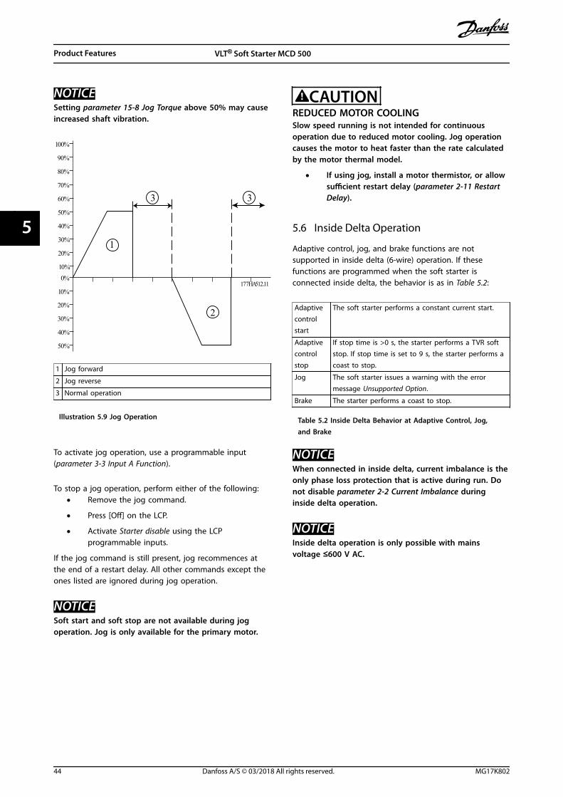
NOTICESetting parameter 15-8 Jog Torque above 50% may causeincreased shaft vibration.
7 0 %
6 0 %
5 0 %
3 0 %
1 0 %
4 0 %
2 0 %
8 0 %
9 0 %
1 0 0 %
3 0 %
4 0 %
5 0 %
2 0 %
1 0 %
0 % 1 7 7 H A 5 1 2 . 1 1
3
1
2
3
1 Jog forward
2 Jog reverse
3 Normal operation
Illustration 5.9 Jog Operation
To activate jog operation, use a programmable input(parameter 3-3 Input A Function).
To stop a jog operation, perform either of the following:• Remove the jog command.
• Press [Off] on the LCP.
• Activate Starter disable using the LCPprogrammable inputs.
If the jog command is still present, jog recommences atthe end of a restart delay. All other commands except theones listed are ignored during jog operation.
NOTICESoft start and soft stop are not available during jogoperation. Jog is only available for the primary motor.
CAUTIONREDUCED MOTOR COOLINGSlow speed running is not intended for continuousoperation due to reduced motor cooling. Jog operationcauses the motor to heat faster than the rate calculatedby the motor thermal model.
• If using jog, install a motor thermistor, or allowsufficient restart delay (parameter 2-11 RestartDelay).
5.6 Inside Delta Operation
Adaptive control, jog, and brake functions are notsupported in inside delta (6-wire) operation. If thesefunctions are programmed when the soft starter isconnected inside delta, the behavior is as in Table 5.2:
Adaptivecontrolstart
The soft starter performs a constant current start.
Adaptivecontrolstop
If stop time is >0 s, the starter performs a TVR softstop. If stop time is set to 9 s, the starter performs acoast to stop.
Jog The soft starter issues a warning with the errormessage Unsupported Option.
Brake The starter performs a coast to stop.
Table 5.2 Inside Delta Behavior at Adaptive Control, Jog,and Brake
NOTICEWhen connected in inside delta, current imbalance is theonly phase loss protection that is active during run. Donot disable parameter 2-2 Current Imbalance duringinside delta operation.
NOTICEInside delta operation is only possible with mainsvoltage ≤600 V AC.
Product Features VLT® Soft Starter MCD 500
44 Danfoss A/S © 03/2018 All rights reserved. MG17K802
55
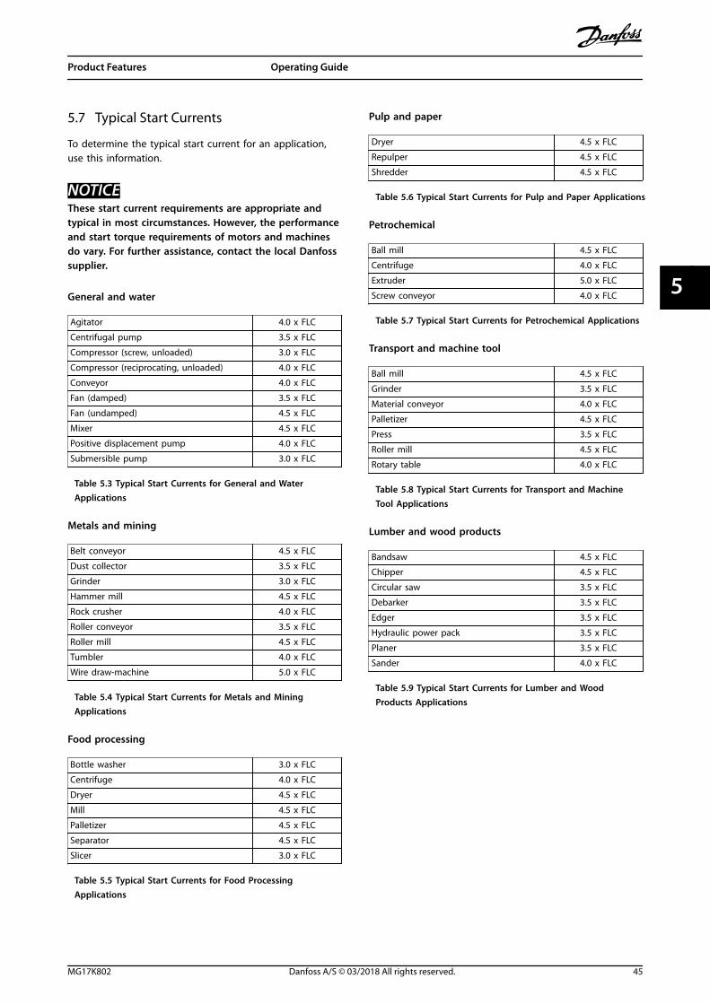
5.7 Typical Start Currents
To determine the typical start current for an application,use this information.
NOTICEThese start current requirements are appropriate andtypical in most circumstances. However, the performanceand start torque requirements of motors and machinesdo vary. For further assistance, contact the local Danfosssupplier.
General and water
Agitator 4.0 x FLC
Centrifugal pump 3.5 x FLC
Compressor (screw, unloaded) 3.0 x FLC
Compressor (reciprocating, unloaded) 4.0 x FLC
Conveyor 4.0 x FLC
Fan (damped) 3.5 x FLC
Fan (undamped) 4.5 x FLC
Mixer 4.5 x FLC
Positive displacement pump 4.0 x FLC
Submersible pump 3.0 x FLC
Table 5.3 Typical Start Currents for General and WaterApplications
Metals and mining
Belt conveyor 4.5 x FLC
Dust collector 3.5 x FLC
Grinder 3.0 x FLC
Hammer mill 4.5 x FLC
Rock crusher 4.0 x FLC
Roller conveyor 3.5 x FLC
Roller mill 4.5 x FLC
Tumbler 4.0 x FLC
Wire draw-machine 5.0 x FLC
Table 5.4 Typical Start Currents for Metals and MiningApplications
Food processing
Bottle washer 3.0 x FLC
Centrifuge 4.0 x FLC
Dryer 4.5 x FLC
Mill 4.5 x FLC
Palletizer 4.5 x FLC
Separator 4.5 x FLC
Slicer 3.0 x FLC
Table 5.5 Typical Start Currents for Food ProcessingApplications
Pulp and paper
Dryer 4.5 x FLC
Repulper 4.5 x FLC
Shredder 4.5 x FLC
Table 5.6 Typical Start Currents for Pulp and Paper Applications
Petrochemical
Ball mill 4.5 x FLC
Centrifuge 4.0 x FLC
Extruder 5.0 x FLC
Screw conveyor 4.0 x FLC
Table 5.7 Typical Start Currents for Petrochemical Applications
Transport and machine tool
Ball mill 4.5 x FLC
Grinder 3.5 x FLC
Material conveyor 4.0 x FLC
Palletizer 4.5 x FLC
Press 3.5 x FLC
Roller mill 4.5 x FLC
Rotary table 4.0 x FLC
Table 5.8 Typical Start Currents for Transport and MachineTool Applications
Lumber and wood products
Bandsaw 4.5 x FLC
Chipper 4.5 x FLC
Circular saw 3.5 x FLC
Debarker 3.5 x FLC
Edger 3.5 x FLC
Hydraulic power pack 3.5 x FLC
Planer 3.5 x FLC
Sander 4.0 x FLC
Table 5.9 Typical Start Currents for Lumber and WoodProducts Applications
Product Features Operating Guide
MG17K802 Danfoss A/S © 03/2018 All rights reserved. 45
5 5
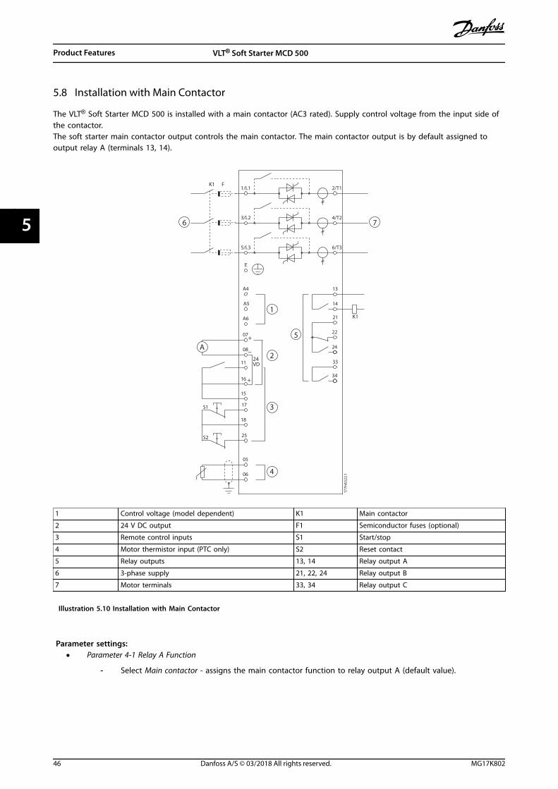
5.8 Installation with Main Contactor
The VLT® Soft Starter MCD 500 is installed with a main contactor (AC3 rated). Supply control voltage from the input side ofthe contactor.The soft starter main contactor output controls the main contactor. The main contactor output is by default assigned tooutput relay A (terminals 13, 14).
K1
K1
F
22
21
6/T3
2/T1
13
14
4/T2
24
33
34
06
05
08
07
17
18
25
11
16
A6
A5
A4
5/L3
3/L2
15
S1
S2
E
1/L1
+
+ 5
6 7
4
2A
3
1
177H
A52
2.1
24 VD
1 Control voltage (model dependent) K1 Main contactor
2 24 V DC output F1 Semiconductor fuses (optional)
3 Remote control inputs S1 Start/stop
4 Motor thermistor input (PTC only) S2 Reset contact
5 Relay outputs 13, 14 Relay output A
6 3-phase supply 21, 22, 24 Relay output B
7 Motor terminals 33, 34 Relay output C
Illustration 5.10 Installation with Main Contactor
Parameter settings:• Parameter 4-1 Relay A Function
- Select Main contactor - assigns the main contactor function to relay output A (default value).
Product Features VLT® Soft Starter MCD 500
46 Danfoss A/S © 03/2018 All rights reserved. MG17K802
55

5.9 Installation with Bypass Contactor
The VLT® Soft Starter MCD 500 is installed with a bypass contactor (AC1 rated). The soft starter run output controls thebypass contactor. The run output is by default assigned to output relay B (terminals 21, 22, 24).
K124 VD
22
21
13
14
24
33
34
06
05
08
07
17
18
25
11
16
A6
A5
A4
15S1
S2
S3
E
+
+
6/T3
2/T1
4/T2
5/L3
3/L2
1/L1
L3B
L1B
L2B
K1
F1
5
6 7
4
2A
3
1
177H
A52
3.1
1 Control voltage (model dependent) K1 Bypass contactor
2 24 V DC output F1 Semiconductor fuses (optional)
3 Remote control inputs S1 Start contact
4 Motor thermistor input (PTC only) S2 Stop contact
5 Relay outputs S3 Reset contact
6 3-phase supply 13, 14 Relay output A
7 Motor terminals 21, 22, 24 Relay output B
33, 34 Relay output C
Illustration 5.11 Installation with Bypass Contactor
Parameter settings:• Parameter 4-4 Relay B Function.
- Select Run - assigns the run output function to output relay B (default value).
Product Features Operating Guide
MG17K802 Danfoss A/S © 03/2018 All rights reserved. 47
5 5
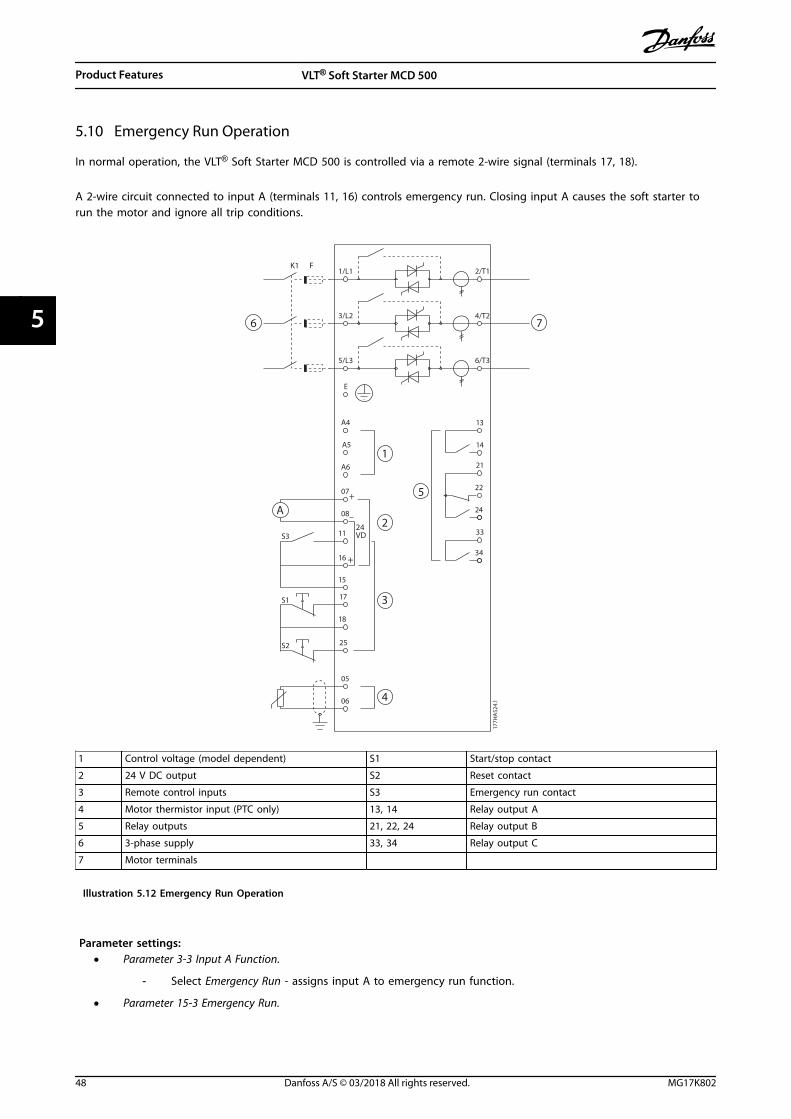
5.10 Emergency Run Operation
In normal operation, the VLT® Soft Starter MCD 500 is controlled via a remote 2-wire signal (terminals 17, 18).
A 2-wire circuit connected to input A (terminals 11, 16) controls emergency run. Closing input A causes the soft starter torun the motor and ignore all trip conditions.
K1 F
24 VD
22
21
6/T3
2/T1
13
14
4/T2
24
33
34
06
05
08
07
17
18
25
11
16
A6
A5
A4
5/L3
3/L2
15
S3
S1
S2
E
1/L1
+
+ 5
6 7
4
2A
3
1
177H
A52
4.1
1 Control voltage (model dependent) S1 Start/stop contact
2 24 V DC output S2 Reset contact
3 Remote control inputs S3 Emergency run contact
4 Motor thermistor input (PTC only) 13, 14 Relay output A
5 Relay outputs 21, 22, 24 Relay output B
6 3-phase supply 33, 34 Relay output C
7 Motor terminals
Illustration 5.12 Emergency Run Operation
Parameter settings:• Parameter 3-3 Input A Function.
- Select Emergency Run - assigns input A to emergency run function.
• Parameter 15-3 Emergency Run.
Product Features VLT® Soft Starter MCD 500
48 Danfoss A/S © 03/2018 All rights reserved. MG17K802
55

- Select Enable - enables the emergency run-mode.
NOTICEAlthough Emergency run fulfills the functionality requirements of fire mode, Danfoss does not recommend its use insituations that require testing and/or compliance with specific standards as it is not certified.
5.11 Auxiliary Trip Circuit
In normal operation, the VLT® Soft Starter MCD 500 is controlled via a remote 2-wire signal (terminals 17, 18).
Input A (terminals 11, 16) is connected to an external trip circuit (such as a low-pressure alarm switch for a pumpingsystem). When the external circuit activates, the soft starter trips and stops the motor.
K1 F
24 VD
22
21
6/T3
2/T1
13
14
4/T2
24
33
34
06
05
08
07
17
18
25
11
16
A6
A5
A4
5/L3
3/L2
15
S3
S1
S2
E
1/L1
+
+ 5
6 7
4
2A
3
1
177H
A52
5.1
1 Control voltage (model dependent) S1 Start/stop contact
2 24 V DC output S2 Reset contact
3 Remote control inputs S3 Auxiliary trip contact
4 Motor thermistor input (PTC only) 13, 14 Relay output A
5 Relay outputs 21, 22, 24 Relay output B
6 3-phase supply 33, 34 Relay output C
7 Motor terminals
Illustration 5.13 Auxiliary Trip Circuit
Product Features Operating Guide
MG17K802 Danfoss A/S © 03/2018 All rights reserved. 49
5 5
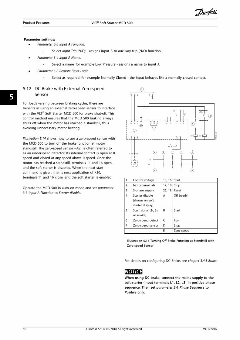
Parameter settings:• Parameter 3-3 Input A Function.
- Select Input Trip (N/O) - assigns input A to auxiliary trip (N/O) function.
• Parameter 3-4 Input A Name.
- Select a name, for example Low Pressure - assigns a name to input A.
• Parameter 3-8 Remote Reset Logic.
- Select as required, for example Normally Closed - the input behaves like a normally closed contact.
5.12 DC Brake with External Zero-speedSensor
For loads varying between braking cycles, there arebenefits in using an external zero-speed sensor to interfacewith the VLT® Soft Starter MCD 500 for brake shut-off. Thiscontrol method ensures that the MCD 500 braking alwaysshuts off when the motor has reached a standstill, thusavoiding unnecessary motor heating.
Illustration 5.14 shows how to use a zero-speed sensor withthe MCD 500 to turn off the brake function at motorstandstill. The zero-speed sensor (-A2) is often referred toas an underspeed detector. Its internal contact is open at 0speed and closed at any speed above 0 speed. Once themotor has reached a standstill, terminals 11 and 16 open,and the soft starter is disabled. When the next startcommand is given, that is next application of K10,terminals 11 and 16 close, and the soft starter is enabled.
Operate the MCD 500 in auto-on mode and set parameter3-3 Input A Function to Starter disable.
-F1
L3L2L1 N E
-K10
L1 L2 L3 E
T1 T2 T3
A5A4 A6 15 16 17 18 25
11 16
-K10-K11
-K10
-K11
T3T2T1
M3
-K11-K10
-A2
177H
A61
9.20
12
3
4
A
5
6
4
B D EC
1 Control voltage 15, 16 Start
2 Motor terminals 17, 18 Stop
3 3-phase supply 25, 18 Reset
4 Starter disable(shown on softstarter display)
A Off (ready)
5 Start signal (2-, 3-,or 4-wire)
B Start
6 Zero-speed detect C Run
7 Zero-speed sensor D Stop
E Zero speed
Illustration 5.14 Turning Off Brake Function at Standstill withZero-speed Sensor
For details on configuring DC Brake, see chapter 5.4.5 Brake.
NOTICEWhen using DC brake, connect the mains supply to thesoft starter (input terminals L1, L2, L3) in positive phasesequence. Then set parameter 2-1 Phase Sequence toPositive only.
Product Features VLT® Soft Starter MCD 500
50 Danfoss A/S © 03/2018 All rights reserved. MG17K802
55

5.13 Soft Braking
For high inertia loads, the VLT® Soft Starter MCD 500 can be configured for soft braking.
In this application, the MCD 500 is employed with forward run and braking contactors. When the soft starter receives a startsignal (push-button S1), it closes the forward run contactor (K1) and controls the motor according to the programmedprimary motor settings.
When the soft starter receives a stop signal (push-button S2), it opens the forward run contactor (K1) and closes the brakingcontactor (K2) after a delay of approximately 2–3 s (KT1). K12 is also closed to activate the secondary motor settings, whichare user-programmed for the wanted stopping performance characteristics.
When motor speed approaches 0, the external zero-speed sensor (A2) stops the soft starter and opens the braking contactor(K2).
3
177H
A526
.12
6
5
64
2
31K3T
K2 K10 K11 K12 K13K1
M1
54 55 585756
F1
K2 K1
K12 S2 K13 A2
K1T K1T K2T K3TK1 K2K1 K2S1 K10 K10 Y1
Y2
Y1
Y2
K10
K2T
4/T26/T3 E
1/L13/L2 5/L3
2/T1
33
34
A4 A5 A6 05 06
K12 K11 S3
53
1 Control voltage (model dependent) K10 Run relay
2 Remote control inputs K11 Start relay
3 Motor thermistor input (PTC only) K12 Brake relay
4 Relay outputs K13 Zero-speed detector relay
5 3-phase supply K1 Line contactor (run)
6 Motor terminals K2 Line contactor (brake)
A2 Zero-speed sensor K1T Run delay timer
S1 Start contact K2T Brake delay timer
S2 Stop contact K3T Zero-speed detector delay timer
S3 Reset contact
Illustration 5.15 Soft Braking Configuration
Parameter settings:• Parameter 3-3 Input A Function.
- Select Motor Set Select - assigns input A for motor set selection.
- Set starting performance characteristics using the primary motor set (parameter group 1 Primary MotorSettings).
Product Features Operating Guide
MG17K802 Danfoss A/S © 03/2018 All rights reserved. 51
5 5

- Set braking performance characteristics using the secondary motor settings (parameter group 7 SecondaryMotor Set).
• Parameter 4-7 Relay C Function.
- Select Trip - assigns trip function to output relay C.
NOTICEIf the soft starter trips on supply frequency (parameter 16-5 Frequency) when the braking contactor K2 opens, modifythe settings of parameters 2-8 to 2-10.
5.14 Two-speed Motor
The VLT® Soft Starter MCD 500 can be configured for control of 2-speed Dahlander type motors, using a high-speedcontactor (K1), low-speed contactor (K2), and a star contactor (K3).
NOTICEPole amplitude modulated (PAM) motors alter the speed by effectively changing the stator frequency using externalwinding configuration. Soft starters are not suitable for use with this type of 2-speed motor.
When the soft starter receives a high-speed start signal, it closes the high-speed contactor (K1) and star contactor (K3). Thenit controls the motor according to the primary motor settings (parameters 1-1 to 1-16).
When the soft starter receives a low-speed start signal, it closes the low-speed contactor (K2). This action closes input A andthe soft starter controls the motor according to the secondary motor settings (parameters 7-1 to 7-16).
NOTICEIf the soft starter trips on supply frequency (16-5 Frequency) when the high-speed start signal (7) is removed, modify thesettings of parameters 2-8 to 2-10.
Product Features VLT® Soft Starter MCD 500
52 Danfoss A/S © 03/2018 All rights reserved. MG17K802
55
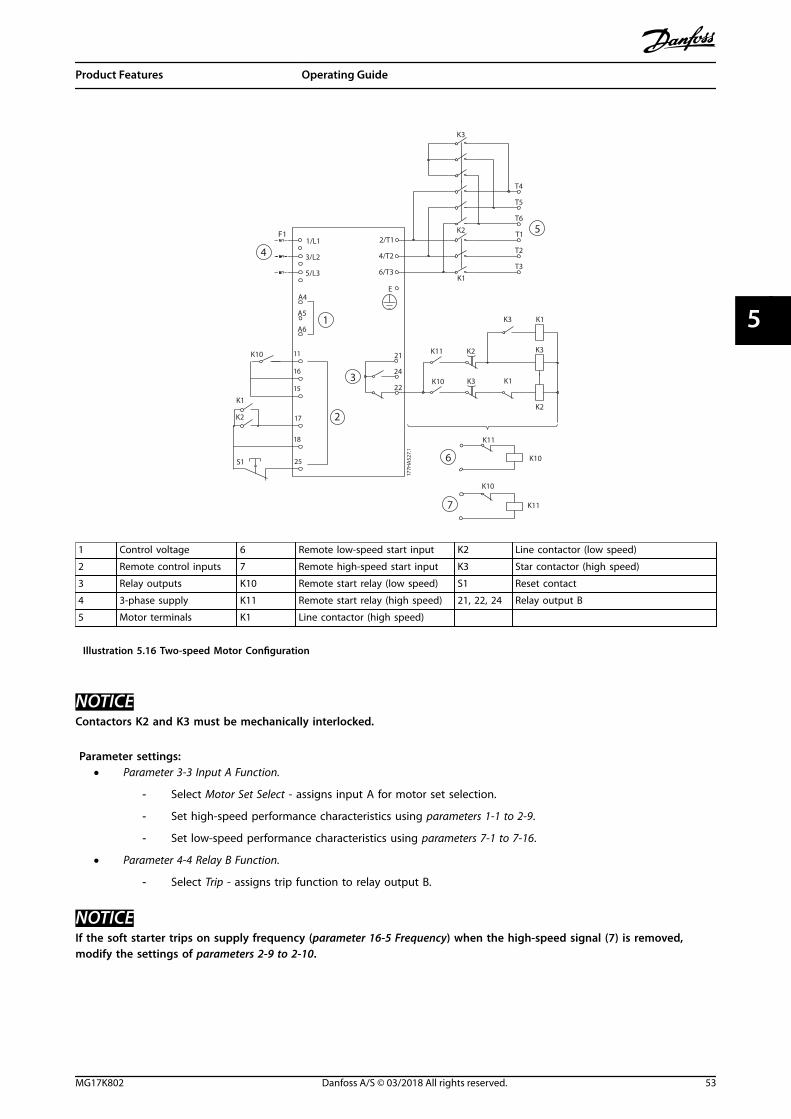
177H
A52
7.1
2/T1
4/T2
6/T3
E
T4
T5
T6
T1
T2
T3
A6
A4
A5
1/L1
3/L2
5/L3
24
22
21
K10
K11
K10
K11
K3K10
K2K11
K1
K2
K3
K1
K3
K1
K3
K2
S1
K2
K1
K10
F1
17
18
25
11
16
153
6
7
5
4
2
1
1 Control voltage 6 Remote low-speed start input K2 Line contactor (low speed)
2 Remote control inputs 7 Remote high-speed start input K3 Star contactor (high speed)
3 Relay outputs K10 Remote start relay (low speed) S1 Reset contact
4 3-phase supply K11 Remote start relay (high speed) 21, 22, 24 Relay output B
5 Motor terminals K1 Line contactor (high speed)
Illustration 5.16 Two-speed Motor Configuration
NOTICEContactors K2 and K3 must be mechanically interlocked.
Parameter settings:• Parameter 3-3 Input A Function.
- Select Motor Set Select - assigns input A for motor set selection.
- Set high-speed performance characteristics using parameters 1-1 to 2-9.
- Set low-speed performance characteristics using parameters 7-1 to 7-16.
• Parameter 4-4 Relay B Function.
- Select Trip - assigns trip function to relay output B.
NOTICEIf the soft starter trips on supply frequency (parameter 16-5 Frequency) when the high-speed signal (7) is removed,modify the settings of parameters 2-9 to 2-10.
Product Features Operating Guide
MG17K802 Danfoss A/S © 03/2018 All rights reserved. 53
5 5

6 Operation
6.1 Control Methods
The VLT® Soft Starter MCD 500 can be controlled:• Via the control keys on the LCP (local control).
• Via the remote inputs (remote control).
• Via the serial communication network.
Control functions• Local control is only available in hand-on mode.
• Remote control is only available in auto-on mode.
• Control via the serial communication network is always disabled in hand-on mode. Enable or disable start/stopcommands via the serial network in auto-on mode by changing the setting of parameter 3-2 Comms in Remote.
The MCD 500 can also be configured to autostart or autostop. Autostart/stop operation is only available in auto-on mode. Inhand-on mode, the soft starter ignores any autostart/stop setting. To configure autostart/stop operation, set parameters 5-1to 5-4.
To switch between hand-on mode and auto-on mode, press the keys on the LCP.• [Hand On]: Start the motor and enter hand-on mode.
• [Off]: Stop the motor and enter hand-on mode.
• [Auto On]: Set the soft starter to auto-on mode.
• [Reset]: Reset a trip (hand-on mode only).
The MCD 500 can also be set to allow local control only or remote control only, using parameter 3-1 Local/Remote.
If parameter 3-1 Local/Remote is set to Remote Control Only, the [Off] key is disabled. Stop the motor by remote control or viathe serial communication network.
Hand-on mode Auto-on mode
To soft start the motor. Press [Hand On] on the LCP. Activate the Start remote input.
To stop the motor. Press [Off] on the LCP. Activate the Stop remote input.
To reset a trip on the soft starter. Press [Reset] on the LCP. Activate the Reset remote input.
Autostart/stop operation. Disabled. Enabled.
Table 6.1 Start, Stop, and Reset in Hand-on Mode and Auto-on Mode
To stop the motor with a coast to stop, regardless of the setting in parameter 1-10 Stop Mode, press [Off] and [Reset] at thesame time. The soft starter removes power from the motor and opens the main contactor, and the motor coasts to stop.
NOTICEBrake and jog functions operate only with in-line connected motors (see chapter 5.6 Inside Delta Operation).
Operation VLT® Soft Starter MCD 500
54 Danfoss A/S © 03/2018 All rights reserved. MG17K802
66

6.2 Operation and LCP
6.2.1 Operating Modes
In hand-on mode:• To soft start the motor, press [Hand On] on the
LCP.
• To stop the motor, press [Off] on the LCP.
• To reset a trip on the soft starter, press [Reset] onthe LCP.
• To stop the motor with a coast to stop, regardlessof the setting of parameter 1-10 Stop mode, press[Off] and [Reset] at the same time. The softstarter removes power from the motor and opensthe main contactor, and then the motor coasts tostop.
In auto-on mode:• To soft start the motor, activate the Start remote
input.
• To stop the motor, activate the Stop remote input.
• To reset a trip on the soft starter, activate theReset remote input.
NOTICEBrake and jog functions operate only with in-lineconnected motors (see chapter 4.3.3 Inside Delta Instal-lation).
6.2.2 The LCP
177H
A38
3.10
®
1
2
3
4
5
1 4-line display for status and programming details.
2 Display control keys:[Status]: Returns to the status displays.
[Quick Menu]: Opens the Quick Menu.
[Main Menu]: Opens the Main Menu.
[Alarm Log]: Opens the Alarm Log.
3 Menu navigation keys:[Back]: Exits the menu or parameter, or cancels aparameter change.
[OK]: Enters a menu or parameter, or saves aparameter change.
[▲]/[▼]:
Scroll to the next or previous menu orparameter.
Change the setting of the currentparameter.
Scroll through the status screens.
4 Soft starter local control keys:[Hand On]: Starts the motor and enters localcontrol mode.
[Off]: Stops the motor (only active in hand-onmode).
[Auto On]: Sets the soft starter to auto-on mode.
[Reset]: Resets a trip (hand-on mode only).
5 Remote input status indicators.
Illustration 6.1 LCP Layout
Operation Operating Guide
MG17K802 Danfoss A/S © 03/2018 All rights reserved. 55
6 6

6.3 Remote-mounted LCP
A remote-mounted LCP can be installed with the VLT® SoftStarter MCD 500. The control panel LCP 501 can bemounted up to 3 m (9.8 ft) away from the soft starter, forcontrol and monitoring.
The soft starter can be controlled and programmed fromeither the remote LCP or the LCP on the soft starter. Bothdisplays show the same information.
The remote LCP also allows parameter settings to becopied between soft starters.
6.3.1 Synchronizing the LCP and the SoftStarter
The DB9 cable can be connected/disconnected from theLCP while the soft starter runs.
The first time an LCP is plugged into a soft starter, the softstarter copies its parameter settings to the LCP.
New display detected
If the LCP has previously been used with a VLT® SoftStarter MCD 500, select whether to copy the parametersfrom the LCP to the soft starter, or from the soft starter tothe LCP.
To select the required option:1. Press the [▲] and [▼] keys.
A dotted line surrounds the selected option.
2. Press [OK] to proceed with the Copy Parametersselection.
2a Display to soft starter.
2b Soft starter to display.
Copy parameters
Display to soft starter Soft starter to display
NOTICEIf the parameter software version in the LCP is differentfrom the software version of the soft starter, only Starterto Display is available.
NOTICEWhile the LCP synchronizes, only the [▲], [▼], [OK], and[Off] keys are enabled.
NOTICEThe LCP can be removed or replaced while the softstarter is running. It is not necessary to remove mains orcontrol voltage.
6.4 Welcome Screen
When control power is applied, the soft starter shows thewelcome screen.
Ready S1
Welcome 1.05/2.0/1.13 MCD5-0053-T5-G1-
CV2
Third display line: Software versions for remote LCP, control software,model software.Fourth display line: Product model number.
NOTICEThe LCP version is only shown if a remote LCP 501 isconnected when control power is applied. If no remoteLCP is present, only the control software and modelsoftware versions are shown.
6.5 Local Control Keys
If parameter 3-1 Local/Remote is set to LCL/RMT Anytime orLCL/RMT When OFF, the [Hand On] and [Auto On] keys arealways active. If the soft starter is in auto-on mode,pressing [Hand On] enters hand-on mode and starts themotor.
If parameter 3-1 Local/Remote is set to Remote Control Only,the [Off] key is disabled. Stop the motor by remote controlor via the serial communication network.
6.6 Displays
The LCP shows a wide range of performance informationabout the soft starter. Press [Status] to access the statusdisplay screens, then press [▲] and [▼] to select theinformation to be shown. To return to the status screensfrom within a menu, press [Back] repeatedly, or press[Status]. Available status information:
• Temperature monitoring.
• Programmable screen (see parameters 8-2 to 8-5).
• Current.
• Frequency.
Operation VLT® Soft Starter MCD 500
56 Danfoss A/S © 03/2018 All rights reserved. MG17K802
66
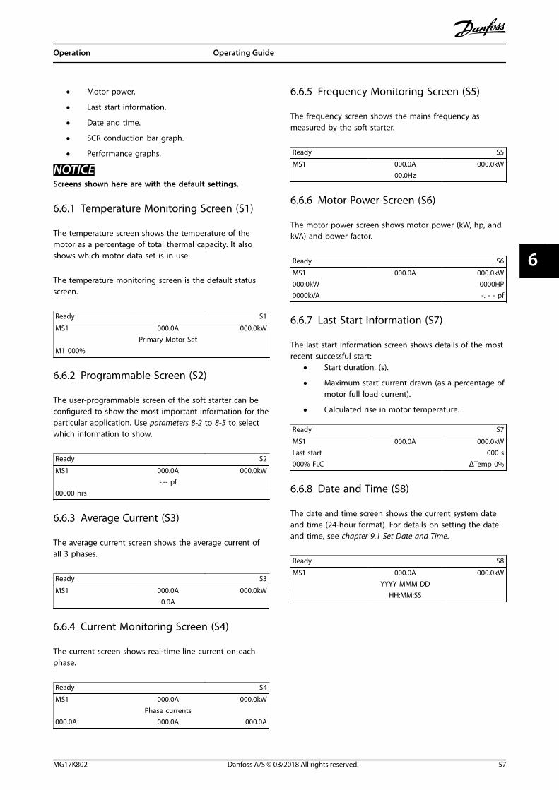
• Motor power.
• Last start information.
• Date and time.
• SCR conduction bar graph.
• Performance graphs.
NOTICEScreens shown here are with the default settings.
6.6.1 Temperature Monitoring Screen (S1)
The temperature screen shows the temperature of themotor as a percentage of total thermal capacity. It alsoshows which motor data set is in use.
The temperature monitoring screen is the default statusscreen.
Ready S1
MS1 000.0A 000.0kW Primary Motor Set
M1 000%
6.6.2 Programmable Screen (S2)
The user-programmable screen of the soft starter can beconfigured to show the most important information for theparticular application. Use parameters 8-2 to 8-5 to selectwhich information to show.
Ready S2
MS1 000.0A 000.0kW -.-- pf
00000 hrs
6.6.3 Average Current (S3)
The average current screen shows the average current ofall 3 phases.
Ready S3
MS1 000.0A 000.0kW 0.0A
6.6.4 Current Monitoring Screen (S4)
The current screen shows real-time line current on eachphase.
Ready S4
MS1 000.0A 000.0kW Phase currents
000.0A 000.0A 000.0A
6.6.5 Frequency Monitoring Screen (S5)
The frequency screen shows the mains frequency asmeasured by the soft starter.
Ready S5
MS1 000.0A 000.0kW 00.0Hz
6.6.6 Motor Power Screen (S6)
The motor power screen shows motor power (kW, hp, andkVA) and power factor.
Ready S6
MS1 000.0A 000.0kW000.0kW 0000HP0000kVA -. - - pf
6.6.7 Last Start Information (S7)
The last start information screen shows details of the mostrecent successful start:
• Start duration, (s).
• Maximum start current drawn (as a percentage ofmotor full load current).
• Calculated rise in motor temperature.
Ready S7
MS1 000.0A 000.0kWLast start 000 s000% FLC ΔTemp 0%
6.6.8 Date and Time (S8)
The date and time screen shows the current system dateand time (24-hour format). For details on setting the dateand time, see chapter 9.1 Set Date and Time.
Ready S8
MS1 000.0A 000.0kW YYYY MMM DD HH:MM:SS
Operation Operating Guide
MG17K802 Danfoss A/S © 03/2018 All rights reserved. 57
6 6

6.6.9 SCR Conduction Bar Graph
The SCR conduction bar graph shows the level ofconduction on each phase.
1 7 7 H
A 5 1
3 . 1 0
Illustration 6.2 Bar Graph
6.6.10 Performance Graphs
The VLT® Soft Starter MCD 500 can show real-timeperformance information for:
• Current.
• Motor temperature.
• Motor kW.
• Motor kVA.
• Motor power factor.
The newest information is shown at the right side of thescreen. Older data is not stored. To allow past performanceto be analyzed, the graph can also be paused. To pause orunpause the graph, press and hold [OK] for more than0.5 s.
NOTICEThe soft starter does not collect data while the graph ispaused. When graphing resumes, a small gap is shownbetween the old data and the new data.
Operation VLT® Soft Starter MCD 500
58 Danfoss A/S © 03/2018 All rights reserved. MG17K802
66
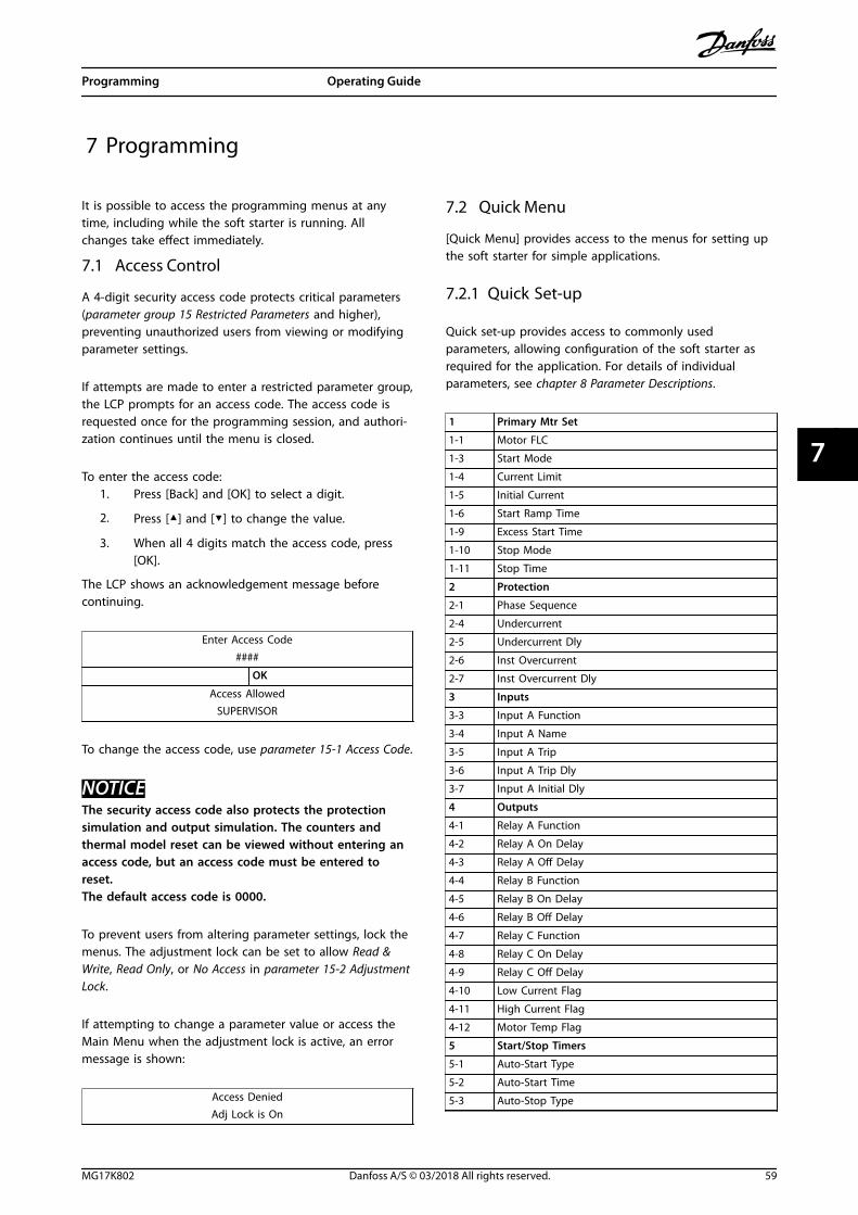
7 Programming
It is possible to access the programming menus at anytime, including while the soft starter is running. Allchanges take effect immediately.
7.1 Access Control
A 4-digit security access code protects critical parameters(parameter group 15 Restricted Parameters and higher),preventing unauthorized users from viewing or modifyingparameter settings.
If attempts are made to enter a restricted parameter group,the LCP prompts for an access code. The access code isrequested once for the programming session, and authori-zation continues until the menu is closed.
To enter the access code:1. Press [Back] and [OK] to select a digit.
2. Press [▲] and [▼] to change the value.
3. When all 4 digits match the access code, press[OK].
The LCP shows an acknowledgement message beforecontinuing.
Enter Access Code####
OK
Access AllowedSUPERVISOR
To change the access code, use parameter 15-1 Access Code.
NOTICEThe security access code also protects the protectionsimulation and output simulation. The counters andthermal model reset can be viewed without entering anaccess code, but an access code must be entered toreset.The default access code is 0000.
To prevent users from altering parameter settings, lock themenus. The adjustment lock can be set to allow Read &Write, Read Only, or No Access in parameter 15-2 AdjustmentLock.
If attempting to change a parameter value or access theMain Menu when the adjustment lock is active, an errormessage is shown:
Access DeniedAdj Lock is On
7.2 Quick Menu
[Quick Menu] provides access to the menus for setting upthe soft starter for simple applications.
7.2.1 Quick Set-up
Quick set-up provides access to commonly usedparameters, allowing configuration of the soft starter asrequired for the application. For details of individualparameters, see chapter 8 Parameter Descriptions.
1 Primary Mtr Set
1-1 Motor FLC
1-3 Start Mode
1-4 Current Limit
1-5 Initial Current
1-6 Start Ramp Time
1-9 Excess Start Time
1-10 Stop Mode
1-11 Stop Time
2 Protection
2-1 Phase Sequence
2-4 Undercurrent
2-5 Undercurrent Dly
2-6 Inst Overcurrent
2-7 Inst Overcurrent Dly
3 Inputs
3-3 Input A Function
3-4 Input A Name
3-5 Input A Trip
3-6 Input A Trip Dly
3-7 Input A Initial Dly
4 Outputs
4-1 Relay A Function
4-2 Relay A On Delay
4-3 Relay A Off Delay
4-4 Relay B Function
4-5 Relay B On Delay
4-6 Relay B Off Delay
4-7 Relay C Function
4-8 Relay C On Delay
4-9 Relay C Off Delay
4-10 Low Current Flag
4-11 High Current Flag
4-12 Motor Temp Flag
5 Start/Stop Timers
5-1 Auto-Start Type
5-2 Auto-Start Time
5-3 Auto-Stop Type
Programming Operating Guide
MG17K802 Danfoss A/S © 03/2018 All rights reserved. 59
7 7

1 Primary Mtr Set
5-4 Auto-Stop Time
8 Display
8-1 Language
8-2 User Scrn Top L
8-3 User Scrn Top R
8-4 User Scrn Btm L
8-5 User Scrn Btm R
Table 7.1 Parameters in the Quick Set-up Menu
7.2.2 Application Set-up Examples
The application set-ups menu makes it easy to configurethe soft starter for common applications. The soft starterselects the parameters relevant to the application andsuggests a typical setting. Each parameter can be adjustedto suit the exact requirements.
On the display, the highlighted values are suggestedvalues. The values indicated by ▶ are the loaded values.
Always set parameter 1-1 Motor FLC to match the motornameplate full load current. The suggested value for motorFLC is the minimum FLC of the soft starter.
Centrifugal pump
Motor full load current
Start mode Adaptive control
Adaptive start profile Early acceleration
Start ramp time 10 s
Stop mode Adaptive control
Adaptive stop profile Late deceleration
Stop time 15 s
Table 7.2 Suggested Values for Centrifugal Pump Applications
Submersible pump
Motor full load current
Start mode Adaptive control
Adaptive start profile Early acceleration
Start ramp time 5 s
Stop mode Adaptive control
Adaptive stop profile Late deceleration
Stop time 5 s
Table 7.3 Suggested Values for Submersible Pump Applications
Damped fan
Motor full load current
Start mode Constant current
Current limit 350%
Table 7.4 Suggested Values for Damped Fan Applications
Undamped fan
Motor full load current
Start mode Adaptive control
Adaptive start profile Constant acceleration
Start ramp time 20 s
Excess start time 30 s
Locked rotor time 20 s
Table 7.5 Suggested Values for Undamped Fan Applications
Compressor screw
Motor full load current
Start mode Constant current
Start ramp time 5 s
Current limit 400%
Table 7.6 Suggested Values for Compressor Screw Applications
Compressor recip
Motor full load current
Start mode Constant current
Start ramp time 10 s
Current limit 450%
Table 7.7 Suggested Values for Compressor Recip Applications
Conveyor
Motor full load current
Start mode Constant current
Start ramp time 5 s
Current limit 400%
Stop mode Adaptive control
Adaptive stop profile Constant deceleration
Stop time 10 s
Table 7.8 Suggested Values for Conveyor Applications
Crusher rotary
Motor full load current
Start mode Constant current
Start ramp time 10 s
Current limit 400%
Excess start time 30 s
Locked rotor time 20 s
Table 7.9 Suggested Values for Crusher Rotary Applications
Programming VLT® Soft Starter MCD 500
60 Danfoss A/S © 03/2018 All rights reserved. MG17K802
77
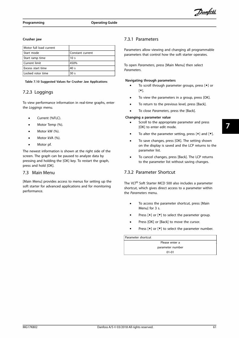
Crusher jaw
Motor full load current
Start mode Constant current
Start ramp time 10 s
Current limit 450%
Excess start time 40 s
Locked rotor time 30 s
Table 7.10 Suggested Values for Crusher Jaw Applications
7.2.3 Loggings
To view performance information in real-time graphs, enterthe Loggings menu.
• Current (%FLC).
• Motor Temp (%).
• Motor kW (%).
• Motor kVA (%).
• Motor pf.
The newest information is shown at the right side of thescreen. The graph can be paused to analyze data bypressing and holding the [OK] key. To restart the graph,press and hold [OK].
7.3 Main Menu
[Main Menu] provides access to menus for setting up thesoft starter for advanced applications and for monitoringperformance.
7.3.1 Parameters
Parameters allow viewing and changing all programmableparameters that control how the soft starter operates.
To open Parameters, press [Main Menu] then selectParameters.
Navigating through parameters• To scroll through parameter groups, press [▲] or
[▼].
• To view the parameters in a group, press [OK].
• To return to the previous level, press [Back].
• To close Parameters, press the [Back].
Changing a parameter value• Scroll to the appropriate parameter and press
[OK] to enter edit mode.
• To alter the parameter setting, press [▲] and [▼].
• To save changes, press [OK]. The setting shownon the display is saved and the LCP returns to theparameter list.
• To cancel changes, press [Back]. The LCP returnsto the parameter list without saving changes.
7.3.2 Parameter Shortcut
The VLT® Soft Starter MCD 500 also includes a parametershortcut, which gives direct access to a parameter withinthe Parameters menu.
• To access the parameter shortcut, press [MainMenu] for 3 s.
• Press [▲] or [▼] to select the parameter group.
• Press [OK] or [Back] to move the cursor.
• Press [▲] or [▼] to select the parameter number.
Parameter shortcut
Please enter aparameter number
01-01
Programming Operating Guide
MG17K802 Danfoss A/S © 03/2018 All rights reserved. 61
7 7

7.3.3 Parameter List
1 Primary Mtr Set 4 Outputs 7-12 Adaptv Ctrl Gain-2
1-1 Motor FLC 4-1 Relay A Function 7-13 Adaptv Start Prof-2
1-2 Locked Rotor Time 4-2 Relay A On Delay 7-14 Adaptv Stop Prof-2
1-3 Start Mode 4-3 Relay A Off Delay 7-15 Brake Torque-2
1-4 Current Limit 4-4 Relay B Function 7-16 Brake Time-2
1-5 Initial Current 4-5 Relay B On Delay 8 Display
1-6 Start Ramp Time 4-6 Relay B Off Delay 8-1 Language
1-7 Kick-start Level 4-7 Relay C Function 8-2 User Scrn Top L
1-8 Kick-start Time 4-8 Relay C On Delay 8-3 User Scrn Top R
1-9 Excess Start Time 4-9 Relay C Off Delay 8-4 User Scrn Btm L
1-10 Stop Mode 4-10 Low Current Flag 8-5 User Scrn Btm R
1-11 Stop Time 4-11 High Current Flag 8-6 Graph Timebase
1-12 Adaptv Control Gain 4-12 Motor Temp Flag 8-7 Graph Max Adj
1-13 Adaptv Start Profile 4-13 Analog Output A 8-8 Graph Min Adj
1-14 Adaptv Stop Profile 4-14 Analog A Scale 8-9 Mains Ref Volt
1-15 Brake Torque 4-15 Analog A Max Adj 15 Restrict Paramtr
1-16 Brake Time 4-16 Analog A Min Adj 15-1 Access Code
2 Protection 5 Start/Stop Timers 15-2 Adjustment Lock
2-1 Phase Sequence 5-1 Auto-Start Type 15-3 Emergency Run
2-2 Current Imbalance 5-2 Auto-Start Time 15-4 Current Calibrat
2-3 Current Imbal Dly 5-3 Auto-Stop Type 15-5 Main Cont Time
2-4 Undercurrent 5-4 Auto-Stop Time 15-6 Bypass Cont Time
2-5 Undercurrent Dly 6 Auto-Reset 15-7 Motor Connection
2-6 Inst Overcurrent 6-1 Auto-Reset Action 15-8 Jog Torque
2-7 Inst Ocrnt Dly 6-2 Maximum Resets 16 Protection Action
2-8 Frequency Check 6-3 Reset Dly Grp A & B 16-1 Motor Overload
2-9 Freq Variation 6-4 Reset Delay Grp C 16-2 Current Imbalance
2-10 Frequency Delay 7 Secondary Mtr Set 16-3 Undercurrent
2-11 Restart Delay 7-1 Motor FLC-2 16-4 Inst Overcurrent
2-12 Motor Temp Check 7-2 Lock Rotor Time-2 16-5 Frequency
3 Inputs 7-3 Start Mode-2 16-6 Heat sink Overtemp
3-1 Local/Remote 7-4 Current Limit-2 16-7 Excess Start Time
3-2 Comms in Remote 7-5 Initial Crnt-2 16-8 Input A Trip
3-3 Input A Function 7-6 Start Ramp-2 16-9 Motor Thermistor
3-4 Input A Name 7-7 Kick-start Lvl-2 16-10 Starter Comms
3-5 Input A Trip 7-8 Kick-start Time-2 16-11 Network Comms
3-6 Input A Trip Dly 7-9 Excess Strt Time-2 16-12 Battery/Clock
3-7 Input A Initial Dly 7-10 Stop Mode-2 16-13 Low Control Volts
3-8 Remote Reset Logic 7-11 Stop Time-2 – –
Programming VLT® Soft Starter MCD 500
62 Danfoss A/S © 03/2018 All rights reserved. MG17K802
77

8 Parameter Descriptions
8.1 Primary Motor Settings
NOTICEDefault settings are marked with *.
The parameters in Primary Motors Settings configure thesoft starter to match the connected motor. Theseparameters describe the operating characteristics of themotor and allow the soft starter to model the motortemperature.
NOTICEParameter 1-2 Locked Rotor Time determines the tripcurrent for motor overload protection. Its default settingprovides motor overload protection:
• Class 10.
• Trip current 105% of FLA, or equivalent.
1-1 Motor FLC
Option: Function:
Modeldependent
Matches the soft starter to the connectedmotor full load current. Set to the full loadcurrent (FLC) rating shown on the motornameplate.
NOTICEThe setting for this parameter sets thebasis for calculation of all current-basedprotection settings.
1-2 Locked Rotor Time
Range: Function:
10 s* [0:01–2:00(min:s)]
Sets the maximum length of the time themotor can sustain locked rotor current fromcold before reaching its maximumtemperature. Set according to the motordatasheet.
1-3 Start Mode
Option: Function:
Selects the soft start mode. Seechapter 5.3 Starting Modes for more details.
Constant current*
Adaptive control
1-4 Current Limit
Range: Function:
350%* [100–600%FLC]
Sets the current limit for constant current andcurrent ramp soft starting as a percentage ofmotor full load current. Seechapter 5.3 Starting Modes for more details.
1-5 Initial Current
Range: Function:
350%* [100–600%FLC]
Sets the initial start current level for currentramp starting as a percentage of motor full loadcurrent. Set so that the motor begins toaccelerate immediately after a start is initiated.If current ramp starting is not required, set theinitial current equal to the current limit. Seechapter 5.3 Starting Modes for more details.
1-6 Start Ramp Time
Range: Function:
10 s* [1–180 s]
Sets the total start time for an adaptive controlstart or the ramp time for current rampstarting (from the initial current to the currentlimit). See chapter 5.3 Starting Modes for moredetails.
1-7 Kick-start Level
Range: Function:
500%* [100–700% FLC] CAUTION
INCREASED TORQUE LEVELKick-start subjects the mechanicalequipment to increased torque levels.
• Ensure that the motor, load,and couplings can handle theadditional torque beforeusing this feature.
Sets the level of the kick-start current.
Parameter Descriptions Operating Guide
MG17K802 Danfoss A/S © 03/2018 All rights reserved. 63
8 8

1-8 Kick-start Time
Range: Function:
0000 ms* [0–2000 ms] CAUTION
INCREASED TORQUE LEVELKick-start subjects the mechanicalequipment to increased torquelevels.
• Ensure that the motor,load, and couplings canhandle the additionaltorque before using thisfeature.
Sets the kick-start duration. A setting of 0disables kick-start. See chapter 5.3 StartingModes for more details.
1-9 Excess Start Time
Range: Function:
Excess start time is the maximum time the softstarter attempts to start the motor. If themotor does not reach full speed within theprogrammed limit, the soft starter trips. Set fora period slightly longer than required for anormal healthy start. A setting of 0 disablesexcess start time protection.
20 s* [0:00–4:00(min:s)]
Set as required.
1-10 Stop Mode
Option: Function:
Selects the stop mode. Seechapter 5.4 Stopping Modes for more details.
Coast to stop*
TVR soft stop
Adaptive control
Brake
1-11 Stop Time
Range: Function:
0s*
[0:00–4:00(min:s)]
Sets the time for soft stopping the motor usingtimed voltage ramp or adaptive control. If a maincontactor is installed, the contactor must remainclosed until the end of the stop time. To controlthe main contactor, use a programmable outputconfigured to Run. Sets the total stopping timewhen using brake. See chapter 5.4 StoppingModes for more details.
1-12 Adaptive Control Gain
Range: Function:
75%* [1–200%] Adjusts the performance of adaptive control.This setting affects both starting and stoppingcontrol.
1-12 Adaptive Control Gain
Range: Function:
NOTICELeave the gain setting at the defaultlevel unless adaptive controlperformance is not satisfactory. If themotor accelerates or decelerates tooquickly at the end of a start or stop,increase the gain setting by 5–10%. Ifthe motor speed fluctuates duringstarting or stopping, decrease the gainsetting slightly.
1-13 Adaptive Start Profile
Option: Function:
Selects which profile the soft starter usesfor an adaptive control soft start. Seechapter 5.4 Stopping Modes for moredetails.
Early acceleration
Constant
acceleration*Late acceleration
1-14 Adaptive Stop Profile
Option: Function:
Selects which profile the soft starter usesfor an adaptive control soft stop. Seechapter 5.4 Stopping Modes for moredetails.
Early deceleration
Constantdeceleration*
Late acceleration
8.1.1 Brake
Brake uses DC injection to slow the motor actively. Seechapter 5.4 Stopping Modes for more details.
1-15 Brake Torque
Range: Function:
20%* [20–100%] Sets the amount of brake torque the softstarter uses to slow the motor.
1-16 Brake Time
Range: Function:
1 s* [1–30 s] Sets the duration for DC injection during abraking stop.
NOTICEThis parameter is used with parameter1-11 Stop Time. See chapter 5.4 StoppingModes for details.
Parameter Descriptions VLT® Soft Starter MCD 500
64 Danfoss A/S © 03/2018 All rights reserved. MG17K802
88

8.2 Protection
2-1 Phase Sequence
Option: Function:
Selects which phase sequences the soft starterallows at a start. During its prestart checks, thesoft starter examines the sequence of thephases at its input terminals. If the actualsequence does not match the selected option,the soft starter trips.
Any sequence*
Positive only
Negative only
8.2.1 Current Imbalance
If the currents on the 3 phases vary by more than aspecified amount, the soft starter can be configured to trip.The imbalance is calculated as the difference between thehighest and lowest currents on all 3 phases, as apercentage of the highest current.
Current imbalance detection is desensitized by 50% duringstarting and soft stopping.
2-2 Current Imbalance
Range: Function:
30%* [10–50%] Sets the trip point for current imbalanceprotection.
2-3 Current Imbalance Delay
Range: Function:
3 s* [0:00–4:00(min:s)]
Slows the response of the soft starter tocurrent imbalance, avoiding trips due tomomentary fluctuations.
8.2.2 Undercurrent
If the average current of all 3 phases drops below aspecified level while the motor is running, the soft startercan be configured to trip.
2-4 Undercurrent
Range: Function:
20%* [0–100%]
Sets the trip point for undercurrent protection,as a percentage of motor full load current. Set toa level between the normal motor workingrange and the motor magnetizing (no load)current (typically 25–35% of full load current). Asetting of 0% disables undercurrent protection.
2-5 Undercurrent Delay
Range: Function:
5 s* [0:00–4:00(min:s)]
Slows the response of the soft starter toundercurrent, avoiding trips due tomomentary fluctuations.
8.2.3 Instant Overcurrent
If the average current of all 3 phases exceeds a specifiedlevel while the motor is running, the soft starter can beconfigured to trip.
2-6 Instantaneous Overcurrent
Range: Function:
400%* [80–600%FLC]
Sets the trip point for instant overcurrentprotection as a percentage of motor fullload current.
2-7 Instantaneous Overcurrent Delay
Range: Function:
0 s* [0:00–1:00(min:s)]
Slows the response of the soft starter toovercurrent, avoiding trips due tomomentary overcurrent events.
8.2.4 Frequency Trip
The soft starter monitors mains frequency throughoutoperation and can be configured to trip if the frequencyvaries beyond a specified tolerance.
2-8 Frequency Check
Option: Function:
Determines when the soft starter monitors for afrequency trip.
Do not check
Start only
Start/run*
Run only
2-9 Frequency Variation
Option: Function:
Selects the soft starter tolerance for frequencyvariation.
±2 Hz
±5 Hz*
±10 Hz
±15 Hz
2-10 Frequency Delay
Range: Function:
1 s* [0:01–4:00(min:s)]
Slows the response of the soft starter tofrequency disturbances, avoiding trips due tomomentary fluctuations.
NOTICEIf the mains frequency drops below35 Hz or rises above 75 Hz, the softstarter trips immediately.
Parameter Descriptions Operating Guide
MG17K802 Danfoss A/S © 03/2018 All rights reserved. 65
8 8
2-11 Restart Delay
Range: Function:
10s*
[00:01–60:00(min:s)]
The soft starter can be configured to force adelay between the end of a stop and thebeginning of the next start. During the restartdelay, the display shows the time remainingbefore another start can be attempted.
NOTICEThe restart delay is measured from theend of each stop. Changes to the restartdelay setting take effect after the nextstop.
2-12 Motor Temperature Check
Option: Function:
Selects whether the soft starter verifies that themotor has sufficient thermal capacity for asuccessful start. The soft starter compares thecalculated motor temperature with thetemperature rise from the last motor start. The softstarter only operates if the motor is cool enoughto start successfully.
Do notcheck*
Check
8.3 Inputs
3-1 Local/Remote
Option: Function:
Selects when the [Auto On] and [Hand On]can be used to switch to hand-on mode orauto-on mode.
Lcl/rmtanytime*
Change between local and remote control atany time.
Local controlonly
All remote inputs are disabled.
Remote controlonly
[Hand On] and [Auto On] are disabled.
3-2 Comms in Remote
Option: Function:
Selects whether the soft starter accepts startand stop commands from the serial communi-cation network when in Remote mode.
Commands that are always enabled:
• Force comms trip.
• Local/remote control.
• Test start.
• Reset.
Disable ctrl inRMT
Enable ctrl inRMT*
3-3 Input A Function
Option: Function:
Selects the function of input A.
Motor setselect*
The soft starter can be configured with 2separate sets of motor data. The primary motordata is programmed using parameters 1-1 to 1-16.The secondary motor data is programmed usingparameters 7-1 to 7-16.To use the secondary motor data, set thisparameter to Motor Set Select and close terminals11 and 16 before giving a start command. Thesoft starter checks which motor data to use at astart and uses that motor data for the entirestart/stop cycle.
Input trip(N/O)
Input A can be used to trip the soft starter. Whenthis parameter is set to Input Trip (N/O), a closedcircuit across terminals 11 and 16 trips the softstarter (parameters 3-5 to 3-7).
Input trip(N/C)
When this parameter is set to Input Trip (N/C), anopen circuit across terminals 11 and 16 trips thesoft starter (parameters 3-5 to 3-7).
Local/remoteselect
Input A can be used to select between local andremote control, instead of using the LCP keys.When the input is open, the soft starter is inhand-on mode and can be controlled via the LCP.When the input is closed, the soft starter is inremote mode. The [Hand On] and [Auto On] keysare disabled, and the soft starter ignores anylocal/remote select command from the serialcommunications network.To use Input A to select between local andremote control, set parameter 3-1 Local/Remote toLCL/RMT Anytime.
Emergencyrun
In emergency run, the soft starter continues torun until stopped, ignoring all trips and warnings(see parameter 15-3 Emergency Run for details).Closing the circuit across terminals 11 and 16activates emergency run.Opening the circuit ends emergency run and thesoft starter stops the motor.
Starterdisable
The soft starter can be disabled via the controlinputs. An open circuit across terminals 11 and16 disables the soft starter. The soft starter doesnot respond to start commands. If running, thesoft starter allows the motor to coast to stop,ignoring the soft stop mode set in parameter1-10 Stop Mode.When the circuit across terminals 11 and 16 isopened, the soft starter allows the motor tocoast to stop.
Jog forward Activates jog operation in a forward direction(operates only in Remote mode).
Jog reverse Activates jog operation in reverse direction(operates only in Remote mode).
Parameter Descriptions VLT® Soft Starter MCD 500
66 Danfoss A/S © 03/2018 All rights reserved. MG17K802
88

3-4 Input A Name
Option: Function:
Selects a message for the LCP to show wheninput A is active.
Input trip*
Low pressure
High pressure
Pump fault
Low level
High level
No flow
Starter disable
Controller
PLC
Vibration alarm
3-5 Input A Trip
Option: Function:
Selects when an input trip can occur.
Always active* A trip can occur at any time when the softstarter is receiving power.
Operating only A trip can occur while the soft starter isrunning, stopping, or starting.
Run only A trip can only occur while the soft starter isrunning.
3-6 Input A Trip Delay
Range: Function:
0 s* [0:00–4:00 (min:s)] Sets delay between the inputactivating and soft starter tripping.
3-7 Input A Initial Delay
Range: Function:
0 s* [00:00–30:00 (min:s)]
Sets a delay before an input trip can occur.The initial delay is counted from the time astart signal is received. The state of the inputis ignored until the initial delay has elapsed.
3-8 Remote Reset Logic
Option: Function:
Selects whether the remote reset input of thesoft starter (terminals 25 and 18) is normallyopen or normally closed.
Normally closed*
Normally open
8.4 Outputs
4-1 Relay A Function
Option: Function:
Selects the function of relay A (normally open).
Off Relay A is not used
Maincontactor*
The relay closes when the soft starter receivesa start command and remains closed as longas the motor receives voltage.
4-1 Relay A Function
Option: Function:
Run The relay closes when the starter changes torun state.
Trip The relay closes when the starter trips.
Warning The relay closes when the starter issues awarning.
Low currentflag
The relay closes when the low current flagactivates (parameter 4-10 Low Current Flag).
High currentflag
The relay closes when the high current flagactivates (parameter 4-11 High Current Flag).
Motor tempflag
The relay closes when the motor temperatureflag activates (parameter 4-12 MotorTemperature Flag).
8.4.1 Relay A Delays
The soft starter can be configured to wait before openingor closing relay A.
4-2 Relay A On Delay
Range: Function:
0 s* [0:00–5:00 (min:s)] Sets the delay for closing relay A.
4-3 Relay A Off Delay
Range: Function:
0 s* [0:00–5:00 (min:s)] Sets the delay for reopening relay A.
8.4.2 Relays B and C
Parameters 4-4 to 4-9 configure the operation of relays Band C in the same way as parameters 4-1 to 4-3 configurerelay A. See parameter 4-2 Relay A On Delay and parameter4-3 Relay A Off Delay for details.
• Relay B is a changeover relay.
• Relay C is normally open.
4-4 Relay B Function
Option: Function:
Selects the function of relay B (changeover).
Off Relay B is not used.
Maincontactor
The relay closes when the soft starter receives astart command and remains closed as long asthe motor is receiving voltage.
Run* The relay closes when the soft starter changesto run state.
Trip The relay closes when the soft starter trips.
Warning The relay closes when the soft starter issues awarning.
Low currentflag
The relay closes when the low current flagactivates (parameter 4-10 Low Current Flag).
High currentflag
The relay closes when the high current flagactivates (parameter 4-11 High Current Flag).
Parameter Descriptions Operating Guide
MG17K802 Danfoss A/S © 03/2018 All rights reserved. 67
8 8
4-4 Relay B Function
Option: Function:
Motor tempflag
The relay closes when the motor temperatureflag activates (parameter 4-12 Motor TemperatureFlag).
4-5 Relay B On Delay
Range: Function:
0 s* [0:00–5:00 (min:s)] Sets the delay for closing relay B.
4-6 Relay B Off Delay
Range: Function:
0 s* [0:00–5:00 (min:s)] Sets the delay for reopening relay B.
4-7 Relay C Function
Option: Function:
Selects the function of relay C (normally open).
Off Relay C is not used.
Maincontactor
The relay closes when the soft starter receives astart command and remains closed as long asthe motor is receiving voltage.
Run The relay closes when the soft starter changesto run state.
Trip* The relay closes when the soft starter trips.
Warning The relay closes when the soft starter issues awarning.
Low currentflag
The relay closes when the low current flagactivates (parameter 4-10 Low Current Flag).
High currentflag
The relay closes when the high current flagactivates (parameter 4-11 High Current Flag).
Motor tempflag
The relay closes when the motor temperatureflag activates (parameter 4-12 Motor TemperatureFlag).
4-8 Relay C On Delay
Range: Function:
0 s* [0:00–5:00 (min:s)] Sets the delay for closing relay C.
4-9 Relay C Off Delay
Range: Function:
0 s* [0:00–5:00 (min:s)] Sets the delay for reopening relay C.
8.4.3 Low Current Flag and High CurrentFlag
The soft starter has low and high current flags to give earlywarning of abnormal operation. The current flags can beconfigured to indicate an abnormal current level duringoperation between the normal operating level and theundercurrent or instant overcurrent trip levels. The flagscan signal the situation to external equipment via 1 of theprogrammable outputs. The flags clear when the currentreturns within the normal operating range by 10% of theprogrammed flag value.
4-10 Low Current Flag
Range: Function:
50%* [1–100%FLC]
Sets the level at which the low currentflag operates, as a percentage of motorfull load current.
4-11 High Current Flag
Range: Function:
100%* [50–600%FLC]
Sets the level at which the high currentflag operates, as a percentage of motorfull load current.
8.4.4 Motor Temperature Flag
The soft starter has a motor temperature flag to give earlywarning of abnormal operation. The flag can indicate thatthe motor is operating above its normal operatingtemperature, but lower than the overload limit. The flagcan signal the situation to external equipment via 1 of theprogrammable outputs.
4-12 Motor Temperature Flag
Range: Function:
80%* [0–160%] Sets the level at which the motor temperatureflag operates, as a percentage of the motorthermal capacity.
8.4.5 Analog Output A
The soft starter has an analog output, which can beconnected to associated equipment to monitor motorperformance.
4-13 Analog Output A
Option: Function:
Selects which information is reported via analogoutput A.
Current (%FLC)*
Current as a percentage of motor full load current.
Motortemp (%)
Motor temperature as a percentage of the thermalcapacity of the motor.
Motor kW(%)
Measured motor kW, as a percentage of maximumkW.
Motor kVA(%)
Measured motor kilovolt amperes, as a percentageof maximum kVA.
Motor pf Motor power factor, measured by the soft starter.
• Measure motor kW: √3 x average currentx mains reference voltage x measurepower factor.
• Maximum motor kW: √3 x motor FLC xmains reference voltage. Power factor isassumed to be 1.
• Measure motor kVA: √3 x average currentx main reference voltage.
Parameter Descriptions VLT® Soft Starter MCD 500
68 Danfoss A/S © 03/2018 All rights reserved. MG17K802
88
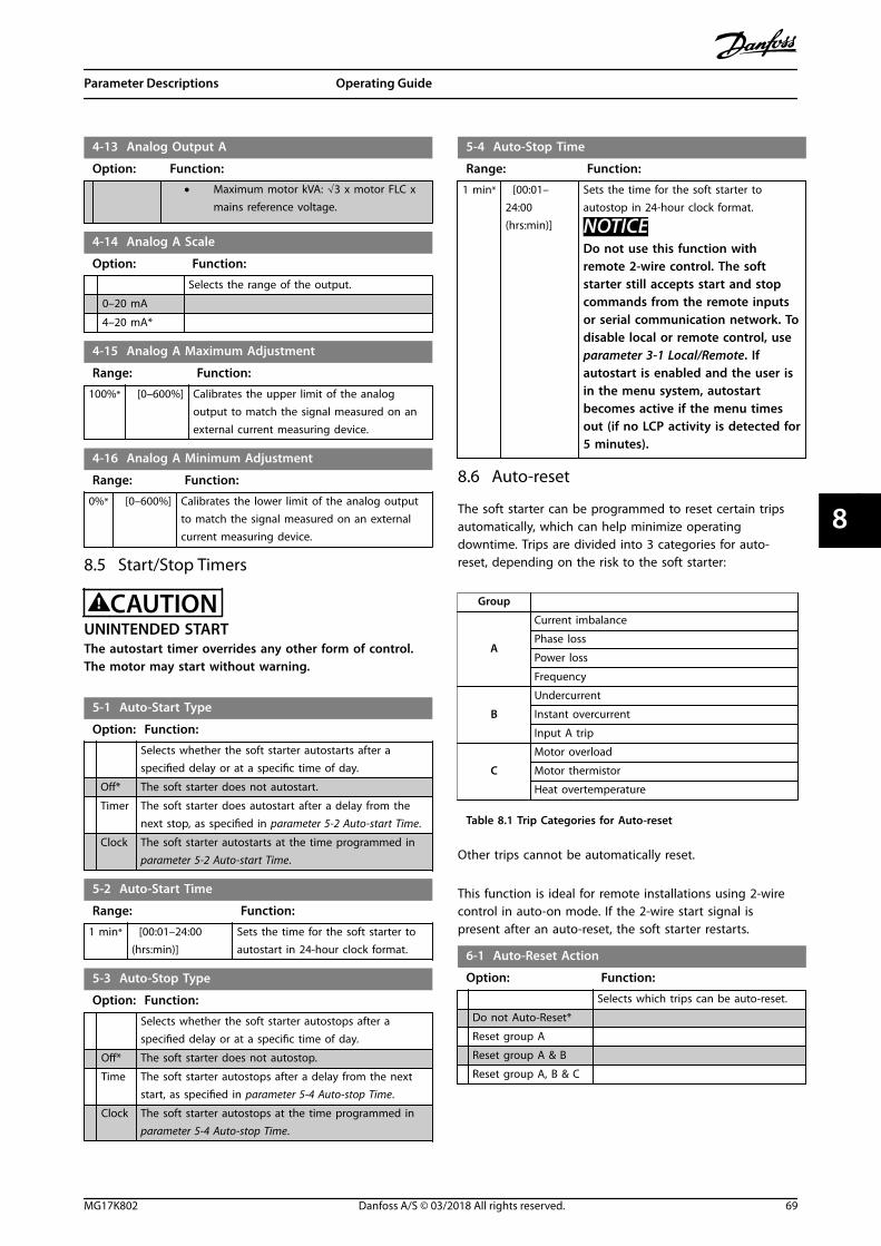
4-13 Analog Output A
Option: Function:
• Maximum motor kVA: √3 x motor FLC xmains reference voltage.
4-14 Analog A Scale
Option: Function:
Selects the range of the output.
0–20 mA
4–20 mA*
4-15 Analog A Maximum Adjustment
Range: Function:
100%* [0–600%] Calibrates the upper limit of the analogoutput to match the signal measured on anexternal current measuring device.
4-16 Analog A Minimum Adjustment
Range: Function:
0%* [0–600%] Calibrates the lower limit of the analog outputto match the signal measured on an externalcurrent measuring device.
8.5 Start/Stop Timers
CAUTIONUNINTENDED STARTThe autostart timer overrides any other form of control.The motor may start without warning.
5-1 Auto-Start Type
Option: Function:
Selects whether the soft starter autostarts after aspecified delay or at a specific time of day.
Off* The soft starter does not autostart.
Timer The soft starter does autostart after a delay from thenext stop, as specified in parameter 5-2 Auto-start Time.
Clock The soft starter autostarts at the time programmed inparameter 5-2 Auto-start Time.
5-2 Auto-Start Time
Range: Function:
1 min* [00:01–24:00(hrs:min)]
Sets the time for the soft starter toautostart in 24-hour clock format.
5-3 Auto-Stop Type
Option: Function:
Selects whether the soft starter autostops after aspecified delay or at a specific time of day.
Off* The soft starter does not autostop.
Time The soft starter autostops after a delay from the nextstart, as specified in parameter 5-4 Auto-stop Time.
Clock The soft starter autostops at the time programmed inparameter 5-4 Auto-stop Time.
5-4 Auto-Stop Time
Range: Function:
1 min* [00:01–24:00(hrs:min)]
Sets the time for the soft starter toautostop in 24-hour clock format.
NOTICEDo not use this function withremote 2-wire control. The softstarter still accepts start and stopcommands from the remote inputsor serial communication network. Todisable local or remote control, useparameter 3-1 Local/Remote. Ifautostart is enabled and the user isin the menu system, autostartbecomes active if the menu timesout (if no LCP activity is detected for5 minutes).
8.6 Auto-reset
The soft starter can be programmed to reset certain tripsautomatically, which can help minimize operatingdowntime. Trips are divided into 3 categories for auto-reset, depending on the risk to the soft starter:
Group
A
Current imbalance
Phase loss
Power loss
Frequency
B
Undercurrent
Instant overcurrent
Input A trip
C
Motor overload
Motor thermistor
Heat overtemperature
Table 8.1 Trip Categories for Auto-reset
Other trips cannot be automatically reset.
This function is ideal for remote installations using 2-wirecontrol in auto-on mode. If the 2-wire start signal ispresent after an auto-reset, the soft starter restarts.
6-1 Auto-Reset Action
Option: Function:
Selects which trips can be auto-reset.
Do not Auto-Reset*
Reset group A
Reset group A & B
Reset group A, B & C
Parameter Descriptions Operating Guide
MG17K802 Danfoss A/S © 03/2018 All rights reserved. 69
8 8

6-2 Maximum Resets
Range: Function:
1* [1–5] Sets how many times the soft starter auto-resets if itcontinues to trip. The reset counter increases by 1each time the soft starter auto-resets and decreasesby 1 after each successful start/stop cycle.
NOTICEIf the starter is manually reset, the reset counter returnsto 0.
8.6.1 Auto-reset Delay
The soft starter can be configured to wait before auto-resetting a trip. Separate delays can be set for trips ingroups A and B, or in group C.
6-3 Reset Delay Groups A & B
Range: Function:
5 s* [00:05–15:00 (min:s)] Sets the delay before resetting groupA and group B trips.
6-4 Reset Delay Group C
Range: Function:
5 minutes* [5–60 (minutes)] Sets the delay before resettinggroup C trips.
8.7 Secondary Motor Set
See parameters 1-1 to 1-16 for details.
7-1 Motor FLC-2
Range: Function:
[Motor dependent] Sets the secondary motor full loadcurrent.
7-2 Locked Rotor Time-2
Range: Function:
10 s* [0:01–2:00(min:s)]
Sets the maximum length of the time themotor can run at locked rotor current fromcold before reaching its maximumtemperature. Set according to the motordatasheet.If this information is not available, set thevalue to <20 s.
7-3 Start Mode-2
Option: Function:
Selects the soft start mode.
Constant current*
Adaptive control
7-4 Current Limit-2
Range: Function:
350%* [100–600%FLC]
Sets the current limit for constant currentand current ramp soft starting, as apercentage of motor full load current.
7-5 Initial Current-2
Range: Function:
350%* [100–600%FLC]
Sets the initial start current level for currentramp starting, as a percentage of motor fullload current. Set so that the motor begins toaccelerate immediately after a start is initiated.If current ramp starting is not required, set theinitial current equal to the current limit.
7-6 Start Ramp Time-2
Range: Function:
10 s* [1–180 s] Sets the total start time for an adaptive controlstart or the ramp time for current rampstarting (from the initial current to the currentlimit).
7-7 Kick-start Level-2
Range: Function:
500%* [100–700% FLC] Sets the level of the kick-start current.
7-8 Kick-start Time-2
Range: Function:
0000 ms* [0–2000 ms] Sets the kick-start duration. A setting of0 disables kick-start.
7-9 Excess Start Time-2
Range: Function:
Excess start time is the maximum time the softstarter attempts to start the motor. If themotor does not reach full speed within theprogrammed limit, the soft starter trips. Set fora period slightly longer than required for anormal healthy start. A setting of 0 disablesexcess start time protection.
20 s* [0:00–4:00(min:s)]
Set as required.
7-10 Stop Mode-2
Option: Function:
Selects the stop mode.
Coast to stop*
TVR soft stop
Adaptive control
Brake
7-11 Stop Time-2
Range: Function:
0 s* [0:00–4:00 (min:s)] Sets the stop time.
Parameter Descriptions VLT® Soft Starter MCD 500
70 Danfoss A/S © 03/2018 All rights reserved. MG17K802
88

7-12 Adaptive Control Gain-2
Range: Function:
75%* [1–200%] Adjusts the performance of adaptive control.The setting affects both starting and stoppingcontrol.
NOTICELeave the gain setting at the defaultlevel unless adaptive controlperformance is not satisfactory.If the motor accelerates or deceleratesquickly at the end of a start or stop,increase the gain setting by 5–10%. Ifthe motor speed fluctuates duringstarting or stopping, decrease the gainsetting slightly.
7-13 Adaptive Start Profile-2
Option: Function:
Selects which profile the soft starteruses for an adaptive control soft start.
Early acceleration
Constant acceleration*
Late acceleration
7-14 Adaptive Stop Profile-2
Option: Function:
Selects which profile the soft starteruses for an adaptive control soft stop.
Early deceleration
Constant deceleration*
Late acceleration
7-15 Brake Torque-2
Range: Function:
20%* [20–100%] Sets the amount of brake torque the softstarter uses to slow the motor.
7-16 Brake Time-2
Range: Function:
1 s* [1–30 s] NOTICEThis parameter is used with parameter7-11 Stop Time-2.
Sets the duration for DC injection during abraking stop.
8.8 Display
8-1 Language
Option: Function:
Selects in which language the LCPshows messages and feedback.
English*
Chinese (中丈)
Spanish (Español)
German (Deutsch)
Portuguese (Português)
8-1 Language
Option: Function:
French (Français)
Italian (Italiano)
Russian (Русский)
8.8.1 User-programmable Screen
Selects which 4 items to show on the programmablemonitoring screen.
8-2 User Screen - Top Left
Option: Function:
Selects the item shown in the top left part ofthe screen.
Blank Shows no data in the selected area, allowinglong messages to be shown withoutoverlapping.
Starter state The operating state of the soft starter (starting,running, stopping, or tripped). Only availablefor Top L and Btm L.
Motor current The average current measured on 3 phases.
Motor pf* The motor power factor measured by the softstarter.
Mainsfrequency
The average frequency measured on 3 phases.
Motor kW The motor running power in kW.
Motor hp The motor running power in horse power.
Motor temp The motor temperature, calculated by thethermal model.
kWh The number of kWh the motor has run via thesoft starter.
Hours run The number of hours the motor has run viathe soft starter.
8-3 User Screen - Top Right
Option: Function:
Selects the item shown in the top right part ofthe screen.
Blank* Shows no data in the selected area, allowinglong messages to be shown withoutoverlapping.
Starter state The operating state of the soft starter (starting,running, stopping, or tripped). Only availablefor Top L and Btm L.
Motor current The average current measured on 3 phases.
Motor pf The motor power factor measured by the softstarter.
Mainsfrequency
The average frequency measured on 3 phases.
Motor kW The motor running power in kW.
Motor hp The motor running power in horse power.
Motor temp The motor temperature, calculated by thethermal model.
Parameter Descriptions Operating Guide
MG17K802 Danfoss A/S © 03/2018 All rights reserved. 71
8 8

8-3 User Screen - Top Right
Option: Function:
kWh The number of kWh the motor has run via thesoft starter.
Hours run The number of hours the motor has run viathe soft starter.
8-4 User Screen - Bottom Left
Option: Function:
Selects the item shown in the bottom left partof the screen.
Blank Shows no data in the selected area, allowinglong messages to be shown withoutoverlapping.
Starter state The operating state of the soft starter (starting,running, stopping, or tripped). Only availablefor Top L and Btm L.
Motor current The average current measured on 3 phases.
Motor pf The motor power factor, measured by the softstarter.
Mainsfrequency
The average frequency measured on 3 phases.
Motor kW The motor running power in kW.
Motor hp The motor running power in horse power.
Motor temp The motor temperature, calculated by thethermal model.
kWh The number of kWh the motor has run via thesoft starter.
Hours run* The number of hours the motor has run viathe soft starter.
8-5 User Screen - Bottom Right
Option: Function:
Selects the item shown in the bottom rightpart of the screen.
Blank* Shows no data in the selected area, allowinglong messages to be shown withoutoverlapping.
Starter state The operating state of the soft starter (starting,running, stopping, or tripped). Only availablefor Top L and Btm L.
Motor current The average current measured on 3 phases.
Motor pf The motor power factor measured by the softstarter.
Mainsfrequency
The average frequency measured on 3 phases.
Motor kW The motor running power in kW.
Motor hp The motor running power in horse power.
Motor temp The motor temperature, calculated by thethermal model.
kWh The number of kWh the motor has run via thesoft starter.
Hours run The number of hours the motor has run viathe soft starter.
8.8.2 Performance Graphs
The loggings menu allows the viewing of performanceinformation in real-time graphs.
The newest information is shown at the right side of thescreen. The graph can be paused to analyze data bypressing and holding [OK]. To restart the graph, press andhold [OK].
8-6 Graph Timebase
Option: Function:
Sets the graph time scale. The graph progressivelyreplaces the old data with new data.
10 s*
30 s
1 minute
5 minutes
10 minutes
30 minutes
1 hour
8-7 Graph Maximum Adjustment
Range: Function:
400%* [0–600%] Adjusts the upper limit of the performancegraph.
8-8 Graph Minimum Adjustment
Range: Function:
0%* [0–600%] Adjusts the lower limit of the performancegraph.
8-9 Mains Reference Voltage
Range: Function:
400 V* [100–690 V]
Sets the nominal voltage for the monitoringfunctions of the LCP. The nominal voltage isused to calculate motor kW and kilovoltamperes (kVA), but does not affect the motorcontrol protection of the soft starter.Enter the measured mains voltage.
8.9 Restricted Parameters
15-1 Access Code
Range: Function:
0000* [0000–9999]
Sets the access code to enter the simulationtools and counter resets or the restrictedsection of the programming menu (parametergroup 15 Restricted Parameters and higher).Press [Back] and [OK] to select which digit to
alter, and use [▲] and [▼] to change the value.
NOTICEIf the access code is lost, contact thelocal Danfoss supplier for master accesscode that allows the reprogramming of anew access code.
Parameter Descriptions VLT® Soft Starter MCD 500
72 Danfoss A/S © 03/2018 All rights reserved. MG17K802
88

15-2 Adjustment Lock
Option: Function:
Selects whether the LCP allows parameters to bechanged via the programming menu.
Read &write*
Allows altering parameter values in theprogramming menu.
Read only Prevents users altering parameter values in theprogramming menu. Parameter values can still beviewed.
No access Prevents users adjusting parameters in theprogramming menu unless an access code isentered.
NOTICEChanges to the adjustment lock setting takeeffect only after the programming menuhas been closed.
15-3 Emergency Run
Option: Function:
CAUTIONEQUIPMENT DAMAGEContinued use of emergency run is notrecommended. Emergency run may compromisethe soft starter life as all protections and tripsare disabled.Using the soft starter in Emergency run modevoids the product warranty.
Selects whether the soft starter allows emergency runoperation. In emergency run, the soft starter starts (ifnot already running) and continues to operate untilemergency run ends, ignoring stop commands andtrips.Emergency run is controlled using a programmableinput.When emergency run is activated in internally bypassedmodels which are not running, the soft starter attemptsa normal start while ignoring all trips. If a normal startis not possible, a DOL start via the internal bypasscontactors is attempted. For non-bypassed models, anexternal emergency run bypass contactor may be used.
15-4 Current Calibration
Range: Function:
100%* [85–115%]
Motor current calibration calibrates the softstarter's current monitoring circuits to match anexternal current metering device.Use the following formula to determine thenecessary adjustment:
Calibration (% ) = Current shown on MCD 500 displayCurrent measured by external devicee . g . 102% = 66 A65 ANOTICEThis adjustment affects all current-basedfunctions.
15-5 Main Contactor Time
Range: Function:
400 ms* [100–2000 ms]
Sets the delay period between the softstarter switching the main contactoroutput (terminals 13 and 14) andbeginning the prestart checks (beforestart) or entering the not ready state(after a stop). Set according to the specifi-cations of the main contactor used.
15-6 Bypass Contactor Time
Range: Function:
150 ms* [100–2000 ms]
Sets the soft starter to match the bypasscontactor closing/opening time. Setaccording to the specifications of thebypass contactor used. If the time is tooshort, the soft starter trips.
15-7 Motor Connection
Option: Function:
The soft starter automatically detects the formatof the connection to the motor.
Auto-Detect*
In-line
Inside Delta
15-8 Jog Torque
Range: Function:
50%* [20–100%] NOTICESetting this parameter above 50% maycause increased shaft vibration.
Sets the torque level for jog operation. Seechapter 5.5 Jog Operation for more details.
Parameter Descriptions Operating Guide
MG17K802 Danfoss A/S © 03/2018 All rights reserved. 73
8 8
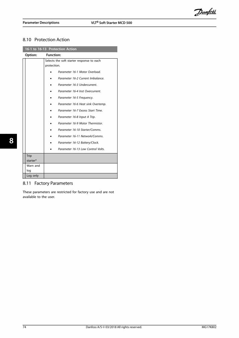
8.10 Protection Action
16-1 to 16-13 Protection Action
Option: Function:
Selects the soft starter response to eachprotection.
• Parameter 16-1 Motor Overload.
• Parameter 16-2 Current Imbalance.
• Parameter 16-3 Undercurrent.
• Parameter 16-4 Inst Overcurrent.
• Parameter 16-5 Frequency.
• Parameter 16-6 Heat sink Overtemp.
• Parameter 16-7 Excess Start Time.
• Parameter 16-8 Input A Trip.
• Parameter 16-9 Motor Thermistor.
• Parameter 16-10 Starter/Comms.
• Parameter 16-11 Network/Comms.
• Parameter 16-12 Battery/Clock.
• Parameter 16-13 Low Control Volts.
Tripstarter*
Warn andlog
Log only
8.11 Factory Parameters
These parameters are restricted for factory use and are notavailable to the user.
Parameter Descriptions VLT® Soft Starter MCD 500
74 Danfoss A/S © 03/2018 All rights reserved. MG17K802
88
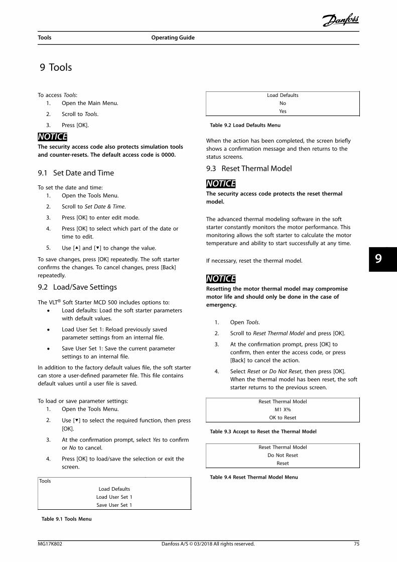
9 Tools
To access Tools:1. Open the Main Menu.
2. Scroll to Tools.
3. Press [OK].
NOTICEThe security access code also protects simulation toolsand counter-resets. The default access code is 0000.
9.1 Set Date and Time
To set the date and time:1. Open the Tools Menu.
2. Scroll to Set Date & Time.
3. Press [OK] to enter edit mode.
4. Press [OK] to select which part of the date ortime to edit.
5. Use [▲] and [▼] to change the value.
To save changes, press [OK] repeatedly. The soft starterconfirms the changes. To cancel changes, press [Back]repeatedly.
9.2 Load/Save Settings
The VLT® Soft Starter MCD 500 includes options to:• Load defaults: Load the soft starter parameters
with default values.
• Load User Set 1: Reload previously savedparameter settings from an internal file.
• Save User Set 1: Save the current parametersettings to an internal file.
In addition to the factory default values file, the soft startercan store a user-defined parameter file. This file containsdefault values until a user file is saved.
To load or save parameter settings:1. Open the Tools Menu.
2. Use [▼] to select the required function, then press[OK].
3. At the confirmation prompt, select Yes to confirmor No to cancel.
4. Press [OK] to load/save the selection or exit thescreen.
Tools Load Defaults
Load User Set 1Save User Set 1
Table 9.1 Tools Menu
Load DefaultsNoYes
Table 9.2 Load Defaults Menu
When the action has been completed, the screen brieflyshows a confirmation message and then returns to thestatus screens.
9.3 Reset Thermal Model
NOTICEThe security access code protects the reset thermalmodel.
The advanced thermal modeling software in the softstarter constantly monitors the motor performance. Thismonitoring allows the soft starter to calculate the motortemperature and ability to start successfully at any time.
If necessary, reset the thermal model.
NOTICEResetting the motor thermal model may compromisemotor life and should only be done in the case ofemergency.
1. Open Tools.
2. Scroll to Reset Thermal Model and press [OK].
3. At the confirmation prompt, press [OK] toconfirm, then enter the access code, or press[Back] to cancel the action.
4. Select Reset or Do Not Reset, then press [OK].When the thermal model has been reset, the softstarter returns to the previous screen.
Reset Thermal ModelM1 X%
OK to Reset
Table 9.3 Accept to Reset the Thermal Model
Reset Thermal ModelDo Not Reset
Reset
Table 9.4 Reset Thermal Model Menu
Tools Operating Guide
MG17K802 Danfoss A/S © 03/2018 All rights reserved. 75
9 9

9.4 Protection Simulation
NOTICEProtection simulation is protected by the security accesscode.
To test the operation and control circuits of the soft starterwithout connecting it to mains voltage, use the softwaresimulation functions.
The protection simulation feature enables the soft starterto confirm that it responds correctly and reports thesituation on the display and across the communicationnetwork.
To use the protection simulation:1. Open the Main Menu.
2. Scroll to Protection Sim and press [OK].
3. To select the protection to simulate, press [▲] and[▼].
4. To simulate the selected protection, press [OK].
5. The screen is shown while [OK] is pressed. Thesoft starter response depends on the protectionaction setting (parameter group 16 ProtectionActions).
6. To return to the simulation list, press [Back].
7. To select another simulation, press [▲] or [▼], orpress [Back] to return to the Main Menu.
MS1 000.0A 0000.0kWTrippedSelected Protection
Table 9.5 Protection Simulation Menu
NOTICEIf the protection trips the soft starter, reset beforesimulating another protection. If the protection action isset to Warn or Log, no reset is required.If the protection is set to Warn & Log, the warningmessage can be viewed only while [OK] is pressed.If the protection is set to Log only, nothing appears onthe screen, but an entry appears in the log.
9.5 Output Signal Simulation
NOTICEThe security access code protects the output signalsimulation.
The LCP allows simulation of output signaling to confirmthat the output relays are operating correctly.
NOTICETo test operation of the flags (motor temperature andlow/high current), set an output relay to the appropriatefunction and monitor the relay behavior.
To use the output signal simulation:1. Open the Main Menu.
2. Scroll to Output Signal Sim and press [OK], thenenter the access code.
3. To select a simulation, press [▲] and [▼], thenpress [OK].
4. To turn the signal on and off, press [▲] and [▼].To confirm correct operation, monitor the state ofthe output.
5. To return to the simulation list, press [Back].
Prog Relay AOff
On
Table 9.6 Output Signal Simulation Menu
9.6 Digital I/O State
This screen shows the status of the digital I/O in order.
The top line of the screen shows:• Start.
• Stop.
• Reset.
• Programmable input.
The bottom line of the screen shows programmableoutputs A, B, and C.
Digital I/O StateInputs: 0100Outputs: 100
Table 9.7 Digital I/O Status Screen
9.7 Temp Sensors State
This screen shows the state of the motor thermistor.The screenshot shows the thermistor state as O (open).
Temp Sensors State Thermistor: OS = shrt H=hot C=cld O=opn
Table 9.8 Motor Thermistor Status Screen
Tools VLT® Soft Starter MCD 500
76 Danfoss A/S © 03/2018 All rights reserved. MG17K802
99

9.8 Alarm Log
The [Alarm Log] key opens the alarm logs, which contain:• Trip log.
• Event log.
• Counters which store information on the softstarter operating history.
9.8.1 Trip Log
The trip log stores details of the 8 most recent trips,including the date and time the trip happened. Trip 1 isthe most recent and trip 8 is the oldest stored trip.
To open the trip log:1. Press [Alarm Log].
2. Scroll to Trip Log and press [OK].
3. To select a trip to view, press [▲] and [▼], thenpress [OK] to show details.
To close the log and return to the main display, press[Back].
9.8.2 Event Log
The event log stores time-stamped details of the 99 mostrecent events (actions, warnings, and trips), including thedate and time of the event. Event 1 is the most recent andevent 99 is the oldest stored event.
To open the event log:1. Press [Alarm Log].
2. Scroll to Event Log and press [OK].
3. To select an event to view, press [▲] and [▼], thenpress [OK] to show details.
To close the log and return to the main display, press[Back].
9.8.3 Counters
NOTICEThe security access code protects the counters function.
The performance counters store statistics on the softstarter operation:
• Hours run (lifetime and time since the last resetof the counter).
• Number of starts (lifetime and time since the lastreset of the counter).
• Motor kWh (lifetime and time since the last resetof the counter).
• Number of times the thermal model has beenreset.
The resettable counters (hours run, starts, and motor kWh)can only be reset if the correct access code is entered.
To view the counters:1. Press [Alarm Log].
2. Scroll to Counters and press [OK].
3. To scroll through the counters, press [▲] and [▼].Press [OK] to view details.
4. To reset a counter, press [OK], then enter theaccess code. Select Reset, then press [OK] toconfirm.
To close the counter and return to the alarm logs, press[Back].
Tools Operating Guide
MG17K802 Danfoss A/S © 03/2018 All rights reserved. 77
9 9

10 Troubleshooting
When a protection condition is detected, the VLT® SoftStarter MCD 500 writes this condition to the event log andmay also trip or issue a warning. The soft starter responsedepends on the protection action settings (parametergroup 16 Protection Actions).
Some protection responses cannot be adjusted. Usually,external events (for example phase loss) or a fault withinthe soft starter cause these trips. These trips do not haveassociated parameters and cannot be set to Warn or Log.
If the soft starter trips:
1. Identify and clear the condition that triggered thetrip.
2. Reset the soft starter.
3. Restart the soft starter.
To reset the soft starter, press [Reset] or activate the Resetremote input.
If the soft starter has issued a warning, it resets itself whenthe cause of the warning has been resolved.
10.1 Trip Messages
Table 10.1 lists the protection mechanisms in the soft starter and the probable cause of the trip. Some of these protectionmechanisms can be adjusted using parameter group 2 Protection and parameter group 16 Protection Action. Other settings arebuilt-in system protections and cannot be set or adjusted.
Display Possible cause/suggested solution
Awaiting data The LCP does not receive data from the control PCB. Check the cable connection and the fitting ofthe display on the soft starter.
Battery/clock A verification error has occurred on the real-time clock, or the back-up battery voltage is low. If thebattery is low and the power is off, date/time settings are lost. Reprogram the date and time.Related parameter:
• Parameter 16-12 Battery Clock.
Controller Name selected for a programmable input. Refer to Input A trip.
Current imbalance Problems with the motor, the environment, or the installation can cause current imbalance, such as:
• An imbalance in the incoming mains voltage.
• A problem with the motor windings.
• A light load on the motor.
• A phase loss on mains terminals L1, L2, or L3 during run mode.
An SCR that has failed open circuit. A failed SCR can only be diagnosed accurately by replacing theSCR and checking the soft starter performance.Related parameters:
• Parameter 2-2 Current Imbalance.
• Parameter 2-3 Current Imbalance Delay.
• Parameter 16-2 Current Imbalance.
Current read err lx Where X is 1, 2, or 3.Internal fault (PCB fault). The output from the current transformer circuit is not close enough to 0when the SCRs are turned off. Contact the local Danfoss supplier for advice.This trip is not adjustable.Related parameters: None.
Troubleshooting VLT® Soft Starter MCD 500
78 Danfoss A/S © 03/2018 All rights reserved. MG17K802
1010
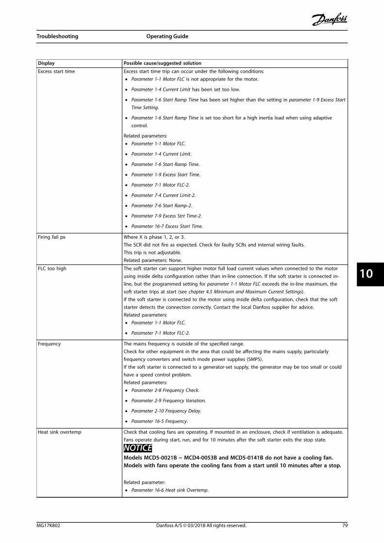
Display Possible cause/suggested solution
Excess start time Excess start time trip can occur under the following conditions:
• Parameter 1-1 Motor FLC is not appropriate for the motor.
• Parameter 1-4 Current Limit has been set too low.
• Parameter 1-6 Start Ramp Time has been set higher than the setting in parameter 1-9 Excess StartTime Setting.
• Parameter 1-6 Start Ramp Time is set too short for a high inertia load when using adaptivecontrol.
Related parameters:
• Parameter 1-1 Motor FLC.
• Parameter 1-4 Current Limit.
• Parameter 1-6 Start Ramp Time.
• Parameter 1-9 Excess Start Time.
• Parameter 7-1 Motor FLC-2.
• Parameter 7-4 Current Limit-2.
• Parameter 7-6 Start Ramp-2.
• Parameter 7-9 Excess Strt Time-2.
• Parameter 16-7 Excess Start Time.
Firing fail px Where X is phase 1, 2, or 3.The SCR did not fire as expected. Check for faulty SCRs and internal wiring faults.This trip is not adjustable.Related parameters: None.
FLC too high The soft starter can support higher motor full load current values when connected to the motorusing inside delta configuration rather than in-line connection. If the soft starter is connected in-line, but the programmed setting for parameter 1-1 Motor FLC exceeds the in-line maximum, thesoft starter trips at start (see chapter 4.5 Minimum and Maximum Current Settings).If the soft starter is connected to the motor using inside delta configuration, check that the softstarter detects the connection correctly. Contact the local Danfoss supplier for advice.Related parameters:
• Parameter 1-1 Motor FLC.
• Parameter 7-1 Motor FLC-2.
Frequency The mains frequency is outside of the specified range.Check for other equipment in the area that could be affecting the mains supply, particularlyfrequency converters and switch mode power supplies (SMPS).If the soft starter is connected to a generator-set supply, the generator may be too small or couldhave a speed control problem.Related parameters:
• Parameter 2-8 Frequency Check.
• Parameter 2-9 Frequency Variation.
• Parameter 2-10 Frequency Delay.
• Parameter 16-5 Frequency.
Heat sink overtemp Check that cooling fans are operating. If mounted in an enclosure, check if ventilation is adequate.Fans operate during start, run, and for 10 minutes after the soft starter exits the stop state.
NOTICEModels MCD5-0021B ~ MCD4-0053B and MCD5-0141B do not have a cooling fan.Models with fans operate the cooling fans from a start until 10 minutes after a stop.
Related parameter:
• Parameter 16-6 Heat sink Overtemp.
Troubleshooting Operating Guide
MG17K802 Danfoss A/S © 03/2018 All rights reserved. 79
10 10

Display Possible cause/suggested solution
High level Name selected for a programmable input. Refer to Input A trip.
High pressure Name selected for a programmable input. Refer to Input A trip.
Input A trip The programmable input is set to a trip function and has activated. Resolve the trigger condition.Related parameters:
• Parameter 3-3 Input A Function.
• Parameter 3-4 Input A Name.
• Parameter 3-5 Input A Trip.
• Parameter 3-6 Input A Trip Delay.
• Parameter 3-7 Input A Initial Delay.
• Parameter 16-8 Input A Trip.
Instantaneous overcurrent There has been a sharp rise in motor current, probably caused by a locked rotor condition (shearpin) while running. Check for a jammed load.Related parameters:
• Parameter 2-6 Instantaneous Overcurrent.
• Parameter 2-7 Instantaneous Overcurrent Delay.
• Parameter 16-4 Inst Overcurrent.
Internal fault X The soft starter has tripped on an internal fault. Contact the local Danfoss supplier with the faultcode (X).Related parameters: None.
L1 phase lossL2 phase lossL3 phase loss
During prestart, check that the soft starter has detected a phase loss as indicated.In run state, the soft starter has detected that the current on the affected phase has droppedbelow 3.3% of the programmed motor FLC for more than 1 s. This current drop indicates thateither the incoming phase or connection to the motor has been lost.For the soft starter and the motor, check:
• The supply connections.
• The input connections.
• The output connections.
A failed SCR can also cause phase loss, particularly an SCR that has failed open circuit. A failed SCRcan only be diagnosed accurately by replacing the SCR and checking the soft starter performance.Related parameters: None.
L1-T1 shortedL2-T2 shortedL3-T3 shorted
During prestart checks, the soft starter has detected a short-circuited SCR or a short circuit withinthe bypass contactor as indicated.Related parameters: None.
Low control volts The soft starter has detected a drop in the control voltage.
• Check the external control supply (terminals A4, A5, A6) and reset the soft starter.
If the external control supply is stable:
• Check if the 24 V supply on the main control PCB is faulty; or
• Check if the bypass driver PCB is faulty (internally bypassed models only).
This protection is not active in ready state.Related parameter:
• Parameter 16-13 Low Control Volts.
Low level Name selected for a programmable input. Refer to Input A trip.
Low pressure Name selected for a programmable input. Refer to Input A trip.
Troubleshooting VLT® Soft Starter MCD 500
80 Danfoss A/S © 03/2018 All rights reserved. MG17K802
1010

Display Possible cause/suggested solution
Motor overload/Motor 2 overload
The motor has reached its maximum thermal capacity.The following can cause overload:
• The soft starter protection settings do not match the motor thermal capacity.
• Excessive starts per hour.
• Excessive throughput.
• Damage to the motor windings.
Resolve the cause of the overload and allow the motor to cool.Related parameters:
• Parameter 1-1 Motor FLC.
• Parameter 1-2 Locked Rotor Time.
• Parameter 1-3 Start Mode.
• Parameter 1-4 Current Limit.
• Parameter 7-1 Motor FLC-2.
• Parameter 7-2 Locked Rotor Time-2.
• Parameter 7-3 Start Mode-2.
• Parameter 7-4 Current Limit-2.
• Parameter 16-1 Motor Overload.
Motor connection tx Where X is 1, 2, or 3.The motor is not connected correctly to the soft starter for in-line or inside delta use.
• Check individual motor connections to the soft starter for power circuit continuity.
• Check connections at the motor terminal box.
This trip is not adjustable.Related parameter:
• Parameter 15-7 Motor Connection.
Motor thermistor The motor thermistor input has been enabled and:
• The resistance at the thermistor input has exceeded 3.6 kΩ for more than 1 s.
• The motor winding has overheated. Identify the cause of the overheating and allow the motorto cool before restarting.
• The motor thermistor input has been opened.
NOTICEIf a valid motor thermistor is no longer used, fit a 1.2 kΩ resistor across terminals 05and 06.
Related parameter:
• Parameter 16-9 Motor Thermistor.
Network communication (betweenmodule and network)
The network master has sent a trip command to the soft starter, or there could be a networkcommunication problem.Check the network for causes of communication inactivity.Related parameter:
• Parameter 16-11 Network/Comms.
No flow Name selected for a programmable input. Refer to Input A trip.
Not ready Check if the soft starter disable function is active. If parameter 3-3 Input A Function is set to Starterdisable and there is an open circuit on terminals 11 and 16, the soft starter does not start.
Parameter out of range • A parameter value is outside the valid range.
The soft starter loads the default value for all affected parameters. To go to the first invalidparameter and adjust the setting, press [Main Menu].Related parameters: None.
Troubleshooting Operating Guide
MG17K802 Danfoss A/S © 03/2018 All rights reserved. 81
10 10

Display Possible cause/suggested solution
Phase sequence The phase sequence on the soft starter mains terminals (L1, L2, L3) is not valid.Check the phase sequence on L1, L2, and L3, and ensure that the setting in parameter 2-1 PhaseSequence is suitable for the installation.Related parameter:
• Parameter 2-1 Phase Sequence.
PLC Name selected for a programmable input. Refer to Input A trip.
Power loss The soft starter is not receiving mains supply on 1 or more phases when a start command is given.Check that the main contactor closes when a start command is given and remains closed until theend of a soft stop.If testing the soft starter with a small motor, it must draw at least 2% of its minimum FLC settingon each phase.Related parameters: None.
Pump fault Name selected for a programmable input. Refer to Input A trip.
Starter/communication (betweenmodule and soft starter)
• There is a problem with the connection between the soft starter and the optional communi-cations module. Remove and reinstall the module. If the problem persists, contact the localdistributor.
• There is an internal communication error within the soft starter. Contact the local distributor.
Related parameter:
• Parameter 16-10 Starter/Comms.
Starter disable Name selected for a programmable input. Refer to Input A trip.
Thermistor cct (thermistor circuit) The thermistor input has been enabled and:
• The resistance at the input has dropped below 20 Ω (the cold resistance of most thermistors isabove this value) or
• A short circuit has occurred. Check and resolve this condition.
Check that a PT100 (RTD) is not connected to terminals 05 and 06. Related parameters: None.
Time - overcurrent The soft starter is internally bypassed and has drawn high current during running. (The 10 Aprotection curve trip has been reached, or the motor current has risen to 600% of the motor FLCsetting.)Related parameters: None.
Undercurrent The motor has experienced a sharp drop in current, caused by loss of load. Causes can includebroken components (shafts, belts, or couplings) or a pump running dry.Related parameters:
• Parameter 2-4 Undercurrent.
• Parameter 2-5 Undercurrent Delay.
• Parameter 16-3 Undercurrent.
Unsupported option (function notavailable in inside delta)
The selected function is not available (for example jog is not supported in inside delta configu-ration).Related parameters: None.
Vibration Name selected for a programmable input. Refer to Input A trip.
VZC fails px Where X is 1, 2, or 3.Internal fault (PCB fault). Contact the local Danfoss supplier for advice.This trip is not adjustable.Related parameters: None.
Table 10.1 Trip Messages
Troubleshooting VLT® Soft Starter MCD 500
82 Danfoss A/S © 03/2018 All rights reserved. MG17K802
1010

10.2 General Faults
Table 10.2 describes situations where the soft starter does not operate as expected but neither trips nor issues a warning.
Symptom Probable cause
The soft starter is not ready. Check input A (11, 16). Check if the soft starter is disabled via a programmable input.If parameter 3-3 Input A Function is set to Starter disable, and there is an open circuiton the corresponding input, the soft starter does not start.
The soft starter does not respond to the [Hand On]and [Reset] keys.
Check if the soft starter is in auto-on mode. When the soft starter is in auto-onmode, the hand-on LED on the soft starter is off. Press [Auto On] once to change tolocal control.
The soft starter does not respond to commandsfrom the control inputs.
• The soft starter is waiting for the restart delay to elapse. Parameter 2-11 Restartdelay controls the length of the restart delay.
• The motor may be too hot to allow a start. If parameter 2-12 Motor temperaturecheck is set to Check, the soft starter only allows a start when it calculates thatthe motor has sufficient thermal capacity to complete the start successfully. Waitfor the motor to cool before attempting another start.
• Check if the soft starter is disabled via a programmable input. If parameter 3-3Input A Function is set to Starter disable, and there is an open circuit on terminals11 and 16, the soft starter does not start. If there is no further need to disablethe soft starter, close the circuit on the input.
NOTICEParameter 3-1 Local/remote controls when the [Auto On] is enabled.
The soft starter does not respond to a startcommand from either the local or remote controls.
• The soft starter may be waiting for the restart delay to elapse. Parameter 2-11Restart delay controls the length of the restart delay.
• The motor may be too hot to allow a start. If parameter 2-12 Motor temperaturecheck is set to Check, the soft starter only allows a start when it calculates thatthe motor has sufficient thermal capacity to complete the start successfully.
• Check if the soft starter is disabled via a programmable input. If parameter 3-3Input A function is set to Starter disable, and there is an open circuit on terminals11 and 16, the soft starter does not start. If there is no further need to disablethe soft starter, close the circuit on the input.
NOTICEParameter 3-1 Local/remote controls when [Auto On] is enabled.
The soft starter does not control the motorcorrectly during start.
• Start performance may be unstable when using a low motor FLC setting(parameter 1-1 Motor FLC). This can affect use on a small test motor with full loadcurrent of 5–50 A.
• Install power factor correction (PFC) capacitors on the supply side of the softstarter. To control a dedicated PFC capacitor contactor, connect the contactor torun relay terminals.
Troubleshooting Operating Guide
MG17K802 Danfoss A/S © 03/2018 All rights reserved. 83
10 10

Symptom Probable cause
Motor does not reach full speed. • If the start current is too low, the motor does not produce enough torque toaccelerate to full speed. The soft starter may trip on excess start time.
NOTICEMake sure that the motor starting parameters are appropriate for theapplication and that the intended motor starting profile is used. Ifparameter 3-3 Input A Function is set to Motor Set Select, check that thecorresponding input is in the expected state.
• Check if the load is jammed. Check the load for severe overloading or a lockedrotor situation.
Erratic motor operation. • The SCRs in the soft starter require at least 5 A of current to latch. If testing thesoft starter on a motor with full load current less than 5 A, the SCRs may notlatch correctly.
Erratic and noisy motor operation. If the soft starter is connected to the motor using inside delta configuration, the softstarter may not be detecting the connection correctly. Contact the local Danfosssupplier for advice.
Soft stop ends too quickly. • The soft stop settings may not be appropriate for the motor and load. Review thesettings of:
- Parameter 1-10 Stop Mode.
- Parameter 1-11 Stop Time.
- Parameter 7-10 Stop Mode-2.
- Parameter 7-11 Stop Time-2.
• If the motor is lightly loaded, soft stop has limited effect.
Adaptive control, DC brake, and jog functions notworking.
• These features are only available with in-line installation. If the soft starter isinstalled inside delta, these features do not operate.
A reset does not occur after an auto-reset whenusing a remote 2-wire control.
• Remove and reapply the remote 2-wire start signal for a restart.
Remote start/stop command overrides autostart/stop settings when using remote 2-wire control.
• Only use autostart/stop in auto-on mode with 3-wire or 4-wire control.
After selecting adaptive control, the motor used an
ordinary start and/or the 2nd start was different
from the 1st start.
• The 1st adaptive control start is Current limit. The soft starter then learns from themotor characteristics. Subsequent starts use adaptive control.
Non-resettable Thermistor Cct trip, when there is alink between thermistor inputs 05 and 06, or whenthe motor thermistor connected between 05 and06 is permanently removed.
• The thermistor input is enabled once a link is fitted and short-circuit protectionhas activated.
Remove the link, then load the default parameter set. This disables the thermistorinput and clears the trip.
Place a 1.2 kΩ resistor across the thermistor input.Turn thermistor protection to Log only (parameter 16-9 Motor Thermistor).
Parameter settings cannot be stored. • Make sure to save the new value by pressing [OK] after adjusting a parametersetting. If pressing [Back], the change is not saved.
• Check that the adjustment lock (parameter 15-2 Adjustment Lock) is set to Read/Write. If the adjustment lock is on, settings can be viewed, but not changed.Knowing the security access code is necessary to change the adjustment locksetting.
• The EEPROM may be faulty on the main control PCB. A faulty EEPROM also tripsthe soft starter, and the LCP shows the message Par. Out of Range. Contact thelocal Danfoss supplier for advice.
The LCP shows message Awaiting data. The LCP does not receive data from the control PCB. Check the cable connection.
Table 10.2 General Fault Messages
Troubleshooting VLT® Soft Starter MCD 500
84 Danfoss A/S © 03/2018 All rights reserved. MG17K802
1010
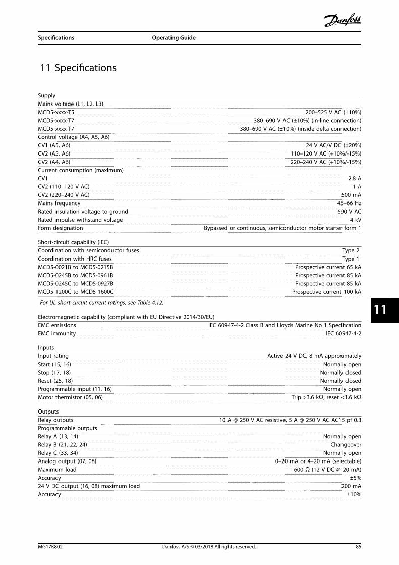
11 Specifications
SupplyMains voltage (L1, L2, L3)MCD5-xxxx-T5 200–525 V AC (±10%)MCD5-xxxx-T7 380–690 V AC (±10%) (in-line connection)MCD5-xxxx-T7 380–690 V AC (±10%) (inside delta connection)Control voltage (A4, A5, A6)CV1 (A5, A6) 24 V AC/V DC (±20%)CV2 (A5, A6) 110–120 V AC (+10%/-15%)CV2 (A4, A6) 220–240 V AC (+10%/-15%)Current consumption (maximum)CV1 2.8 ACV2 (110–120 V AC) 1 ACV2 (220–240 V AC) 500 mAMains frequency 45–66 HzRated insulation voltage to ground 690 V ACRated impulse withstand voltage 4 kVForm designation Bypassed or continuous, semiconductor motor starter form 1
Short-circuit capability (IEC)Coordination with semiconductor fuses Type 2 Coordination with HRC fuses Type 1 MCD5-0021B to MCD5-0215B Prospective current 65 kAMCD5-0245B to MCD5-0961B Prospective current 85 kAMCD5-0245C to MCD5-0927B Prospective current 85 kAMCD5-1200C to MCD5-1600C Prospective current 100 kA
For UL short-circuit current ratings, see Table 4.12.
Electromagnetic capability (compliant with EU Directive 2014/30/EU)EMC emissions IEC 60947-4-2 Class B and Lloyds Marine No 1 SpecificationEMC immunity IEC 60947-4-2
InputsInput rating Active 24 V DC, 8 mA approximatelyStart (15, 16) Normally openStop (17, 18) Normally closedReset (25, 18) Normally closedProgrammable input (11, 16) Normally openMotor thermistor (05, 06) Trip >3.6 kΩ, reset <1.6 kΩ
OutputsRelay outputs 10 A @ 250 V AC resistive, 5 A @ 250 V AC AC15 pf 0.3Programmable outputsRelay A (13, 14) Normally openRelay B (21, 22, 24) ChangeoverRelay C (33, 34) Normally openAnalog output (07, 08) 0–20 mA or 4–20 mA (selectable)Maximum load 600 Ω (12 V DC @ 20 mA)Accuracy ±5%24 V DC output (16, 08) maximum load 200 mAAccuracy ±10%
Specifications Operating Guide
MG17K802 Danfoss A/S © 03/2018 All rights reserved. 85
11 11

EnvironmentalProtectionMCD5-0021B to MCD5-0105B IP20 & NEMA, UL Indoor Type 1MCD5-0131B to MCD5-1600C IP00, UL Indoor Open TypeOperating temperature -10 °C (14 °F) to +60 °C (140 °F), above 40 °C (104 °F) with deratingStorage temperature -25 °C (-13 °F) to +60 °COperating altitude (using MCD PC software) 0–1000 m (0–3281 ft), above 1000 m (3281 ft) with deratingHumidity 5–95% relative humidityPollution degree Pollution degree 3Vibration IEC 60068-2-6
Heat dissipationDuring start 4.5 W per ampereDuring runMCD5-0021B to MCD5-0053B ≤39 W approximatelyMCD5-0068B to MCD5-0105B ≤51 W approximatelyMCD5-0131B to MCD5-0215B ≤120 W approximatelyMCD5-0245B to MCD5-0469B ≤140 W approximatelyMCD5-0525B to MCD5-0961B ≤357 W approximatelyMCD5-0245C to MCD5-0927C 4.5 W per ampere approximatelyMCD5-1200C to MCD5-1600C 4.5 W per ampere approximately
CertificationC✓ IEC 60947-4-2UL/C-ULMCD5-0021B to MCD5-0396B, MCD5-0245C to MCD5-1600CMCD5-0469B to MCD5-0961BMCD5-0021B to MCD5-105BMCD5-0131B to MCD5-1600C
UL 5081)
UL listedUL recognized
IP20, when fitted with optional finger guard kitCE IEC 60947-4-2CCC GB 14048-6Marine(MCD5-0021B to MCD5-0961B) Lloyds Marine No 1 SpecificationRoHS Compliant with EU Directive 2002/95/EC
1) For UL certification extra requirements may apply, depending on the models. For details, see chapter 11.1 UL-compliant Instal-lation.
11.1 UL-compliant Installation
This section details more requirements and configurationsettings for the VLT® Soft Starter MCD 500 to be UL-compliant. See also Table 4.12.
11.1.1 Models MCD5-0021B toMCD5-0105B
There are no additional requirements for these models.
11.1.2 Models MCD5-0131B toMCD5-0215B
• Use with finger guard kit, ordering number175G5662.
• Use the recommended pressure terminal/connector kit. See Table 11.1 for moreinformation.
11.1.3 Models MCD5-0245B toMCD5-0396B
• Use with finger guard kit, ordering number175G5730.
• Use the recommended pressure terminal/connector kit. See Table 11.1 for moreinformation.
11.1.4 Models MCD5-0245C
• Use the recommended pressure terminal/connector kit. See Table 11.1 for moreinformation.
Specifications VLT® Soft Starter MCD 500
86 Danfoss A/S © 03/2018 All rights reserved. MG17K802
1111
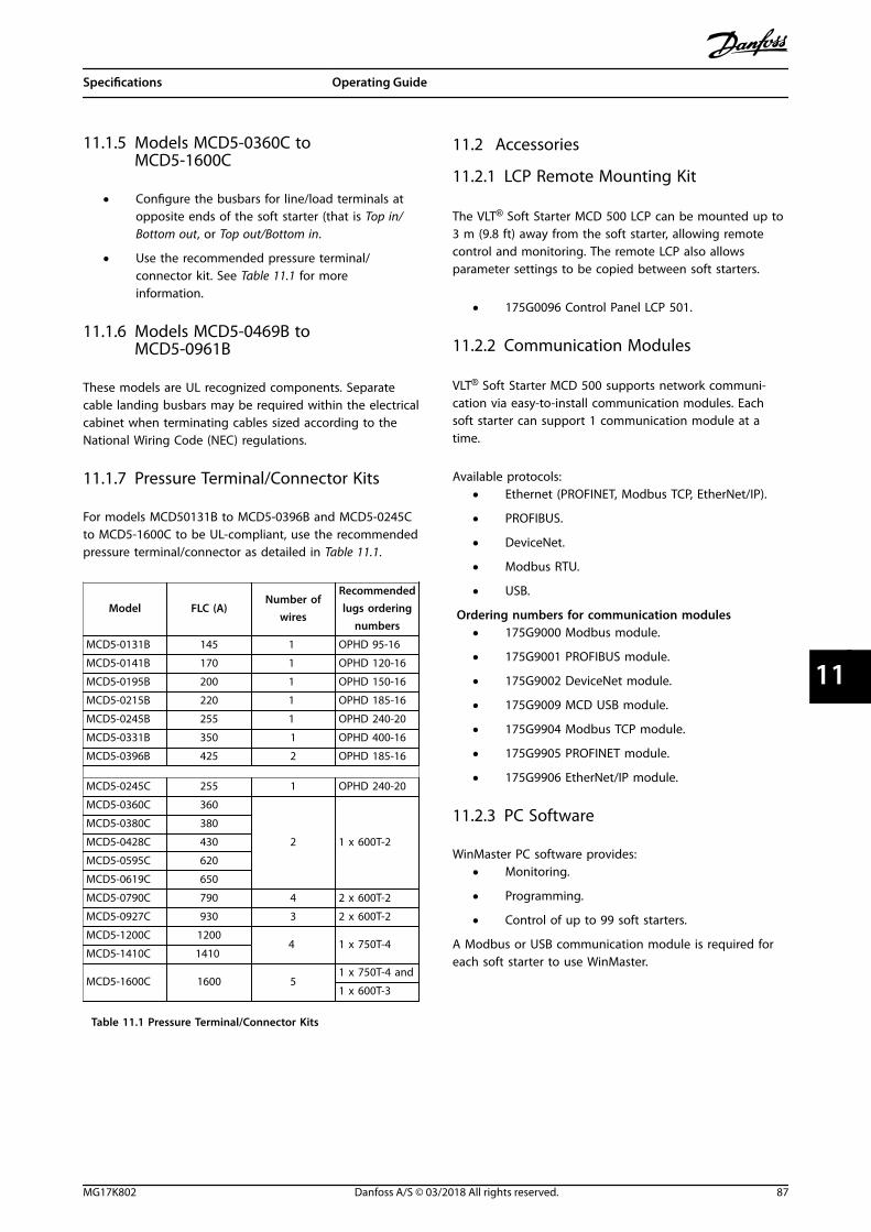
11.1.5 Models MCD5-0360C toMCD5-1600C
• Configure the busbars for line/load terminals atopposite ends of the soft starter (that is Top in/Bottom out, or Top out/Bottom in.
• Use the recommended pressure terminal/connector kit. See Table 11.1 for moreinformation.
11.1.6 Models MCD5-0469B toMCD5-0961B
These models are UL recognized components. Separatecable landing busbars may be required within the electricalcabinet when terminating cables sized according to theNational Wiring Code (NEC) regulations.
11.1.7 Pressure Terminal/Connector Kits
For models MCD50131B to MCD5-0396B and MCD5-0245Cto MCD5-1600C to be UL-compliant, use the recommendedpressure terminal/connector as detailed in Table 11.1.
Model FLC (A)Number of
wires
Recommendedlugs ordering
numbers
MCD5-0131B 145 1 OPHD 95-16
MCD5-0141B 170 1 OPHD 120-16
MCD5-0195B 200 1 OPHD 150-16
MCD5-0215B 220 1 OPHD 185-16
MCD5-0245B 255 1 OPHD 240-20
MCD5-0331B 350 1 OPHD 400-16
MCD5-0396B 425 2 OPHD 185-16
MCD5-0245C 255 1 OPHD 240-20
MCD5-0360C 360
2 1 x 600T-2
MCD5-0380C 380
MCD5-0428C 430
MCD5-0595C 620
MCD5-0619C 650
MCD5-0790C 790 4 2 x 600T-2
MCD5-0927C 930 3 2 x 600T-2
MCD5-1200C 12004 1 x 750T-4
MCD5-1410C 1410
MCD5-1600C 1600 51 x 750T-4 and
1 x 600T-3
Table 11.1 Pressure Terminal/Connector Kits
11.2 Accessories
11.2.1 LCP Remote Mounting Kit
The VLT® Soft Starter MCD 500 LCP can be mounted up to3 m (9.8 ft) away from the soft starter, allowing remotecontrol and monitoring. The remote LCP also allowsparameter settings to be copied between soft starters.
• 175G0096 Control Panel LCP 501.
11.2.2 Communication Modules
VLT® Soft Starter MCD 500 supports network communi-cation via easy-to-install communication modules. Eachsoft starter can support 1 communication module at atime.
Available protocols:• Ethernet (PROFINET, Modbus TCP, EtherNet/IP).
• PROFIBUS.
• DeviceNet.
• Modbus RTU.
• USB.
Ordering numbers for communication modules• 175G9000 Modbus module.
• 175G9001 PROFIBUS module.
• 175G9002 DeviceNet module.
• 175G9009 MCD USB module.
• 175G9904 Modbus TCP module.
• 175G9905 PROFINET module.
• 175G9906 EtherNet/IP module.
11.2.3 PC Software
WinMaster PC software provides:• Monitoring.
• Programming.
• Control of up to 99 soft starters.
A Modbus or USB communication module is required foreach soft starter to use WinMaster.
Specifications Operating Guide
MG17K802 Danfoss A/S © 03/2018 All rights reserved. 87
11 11
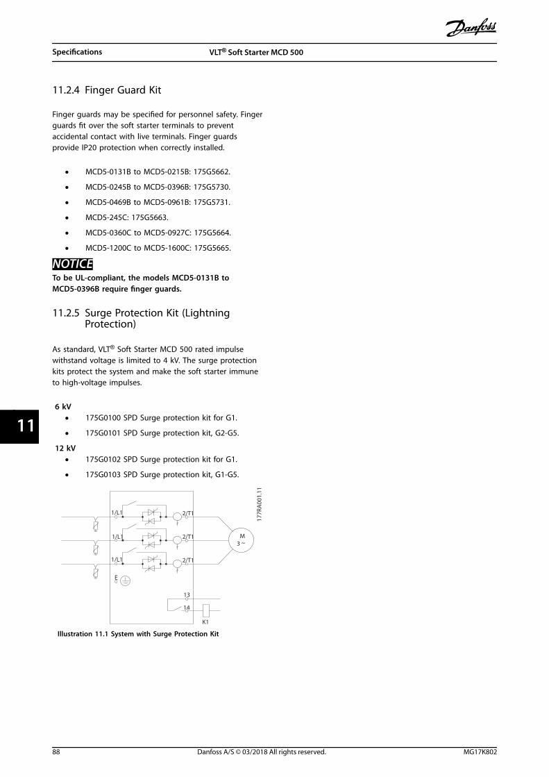
11.2.4 Finger Guard Kit
Finger guards may be specified for personnel safety. Fingerguards fit over the soft starter terminals to preventaccidental contact with live terminals. Finger guardsprovide IP20 protection when correctly installed.
• MCD5-0131B to MCD5-0215B: 175G5662.
• MCD5-0245B to MCD5-0396B: 175G5730.
• MCD5-0469B to MCD5-0961B: 175G5731.
• MCD5-245C: 175G5663.
• MCD5-0360C to MCD5-0927C: 175G5664.
• MCD5-1200C to MCD5-1600C: 175G5665.
NOTICETo be UL-compliant, the models MCD5-0131B toMCD5-0396B require finger guards.
11.2.5 Surge Protection Kit (LightningProtection)
As standard, VLT® Soft Starter MCD 500 rated impulsewithstand voltage is limited to 4 kV. The surge protectionkits protect the system and make the soft starter immuneto high-voltage impulses.
6 kV• 175G0100 SPD Surge protection kit for G1.
• 175G0101 SPD Surge protection kit, G2-G5.
12 kV• 175G0102 SPD Surge protection kit for G1.
• 175G0103 SPD Surge protection kit, G1-G5.
M3 ~
1/L1 2/T1
1/L1
1/L1
2/T1
2/T1
E
13
14
K1
177R
A00
1.11
Illustration 11.1 System with Surge Protection Kit
Specifications VLT® Soft Starter MCD 500
88 Danfoss A/S © 03/2018 All rights reserved. MG17K802
1111
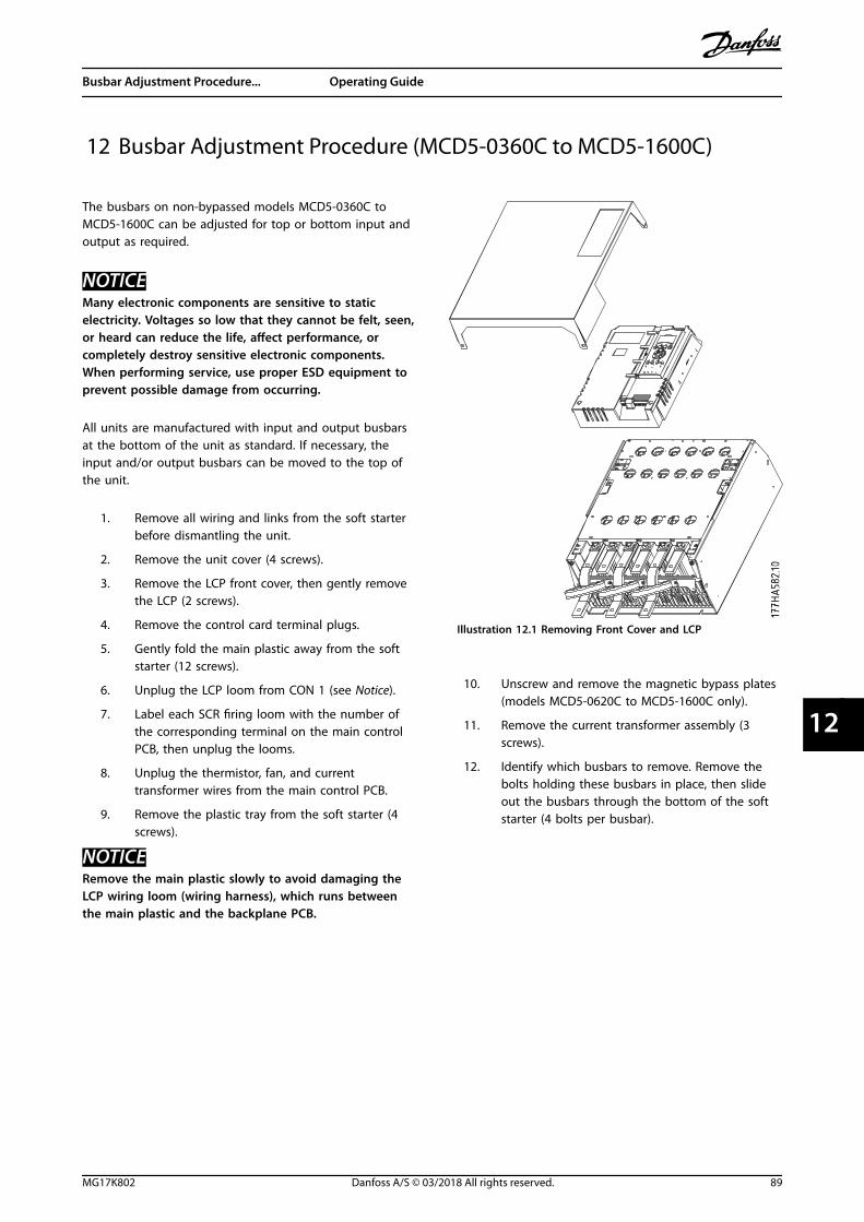
12 Busbar Adjustment Procedure (MCD5-0360C to MCD5-1600C)
The busbars on non-bypassed models MCD5-0360C toMCD5-1600C can be adjusted for top or bottom input andoutput as required.
NOTICEMany electronic components are sensitive to staticelectricity. Voltages so low that they cannot be felt, seen,or heard can reduce the life, affect performance, orcompletely destroy sensitive electronic components.When performing service, use proper ESD equipment toprevent possible damage from occurring.
All units are manufactured with input and output busbarsat the bottom of the unit as standard. If necessary, theinput and/or output busbars can be moved to the top ofthe unit.
1. Remove all wiring and links from the soft starterbefore dismantling the unit.
2. Remove the unit cover (4 screws).
3. Remove the LCP front cover, then gently removethe LCP (2 screws).
4. Remove the control card terminal plugs.
5. Gently fold the main plastic away from the softstarter (12 screws).
6. Unplug the LCP loom from CON 1 (see Notice).
7. Label each SCR firing loom with the number ofthe corresponding terminal on the main controlPCB, then unplug the looms.
8. Unplug the thermistor, fan, and currenttransformer wires from the main control PCB.
9. Remove the plastic tray from the soft starter (4screws).
NOTICERemove the main plastic slowly to avoid damaging theLCP wiring loom (wiring harness), which runs betweenthe main plastic and the backplane PCB.
Illustration 12.1 Removing Front Cover and LCP
10. Unscrew and remove the magnetic bypass plates(models MCD5-0620C to MCD5-1600C only).
11. Remove the current transformer assembly (3screws).
12. Identify which busbars to remove. Remove thebolts holding these busbars in place, then slideout the busbars through the bottom of the softstarter (4 bolts per busbar).
Busbar Adjustment Procedure... Operating Guide
MG17K802 Danfoss A/S © 03/2018 All rights reserved. 89
12 12

Illustration 12.2 Busbars
13. Slide the busbars in through the top of the softstarter. For input busbars, place the short curvedend outside the soft starter. For output busbars,place the unthreaded hole outside the softstarter.
14. Replace the dome washers with the flat facetowards the busbar.
15. Tighten the bolts holding the busbars in place to20 Nm (177 in-lb).
16. Place the current transformer assembly over theinput busbars and screw the assembly to thebody of the soft starter (see Notice).
17. Run all wiring to the side of the soft starter andsecure with cable ties.
Illustration 12.3 Busbars with Cable Ties
NOTICEIf moving the input busbars, the current transformersmust also be reconfigured.
1. Label the current transformers L1, L2, and L3(L1 is leftmost when working from the front ofthe soft starter). Remove the cable ties andunscrew the current transformers from thebracket.
2. Move the current transformer bracket to the topof the soft starter. Position the currenttransformers for the correct phases, then screwthe current transformers to the bracket. Formodels MCD5-0360C to MCD5-0930, place thecurrent transformers on an angle. The left-handlegs of each current transformer are on the toprow of holes and the right-hand legs are on thebottom tabs.
Busbar Adjustment Procedure... VLT® Soft Starter MCD 500
90 Danfoss A/S © 03/2018 All rights reserved. MG17K802
1212

13 Appendix
13.1 Symbols, Abbreviations, andConventions
°C Degrees Celsius
°F Degrees Fahrenheit
AC Alternating current
DC Direct current
DOL Direct on-line
EMC Electro magnetic compatibility
FLA Full load amperage
FLC Full load current
FLT Full load torque
IP Ingress protection
LCP Local control panel
LRA Locked rotor amps
MSTC Motor start time constant
PAM Pole amplitude modulated
PCB Printed circuit board
PELV Protective extra low voltage
PFC Power factor correction
SCCR Short-circuit current rating
SELV Safety extra low voltage
TVR Timed voltage ramp
Table 13.1 Symbols and Abbreviations
ConventionsNumbered lists indicate procedures.Bullet lists indicate other information.
Italicized text indicates:• Cross-reference.
• Link.
• Parameter name.
All dimensions in drawings are in [mm (in)].
Appendix Operating Guide
MG17K802 Danfoss A/S © 03/2018 All rights reserved. 91
13 13
Index
AAbbreviations......................................................................................... 91
AC supply................................................................................................. 18
AC1 rating................................................................................................ 28
AC3 rating................................................................................................ 28
AC-53 rating..................................................................................... 25, 27
Access code............................................ 59, 62, 72, 73, 75, 76, 77, 84
AccessoriesConnector kit.............................................................................. 86, 87
see also Pressure terminalFinger guard kit......................................................................... 86, 88Pressure terminal...................................................................... 86, 87
see also Connector kitSurge protection kit........................................................................ 88
Alarm log.......................................................................................... 55, 77
Altitude......................................................................... 23, 25, 27, 29, 86
Ambient temperature.................................................... 23, 25, 27, 29
ApplicationsUL-compliant..................................................................................... 34
Auto-on mode............................................. 11, 54, 55, 56, 66, 69, 84
Autostart.................................................................................................. 54
Auto-start................................................................................................ 69
Autostart timer...................................................................................... 69
Autostop........................................................................................... 54, 69
Auto-stop................................................................................................. 69
BBrake
Brake.................................................... 42, 43, 44, 54, 55, 64, 70, 71torque.............................................................................. 43, 62, 64, 71DC brake........................................................................... 6, 43, 50, 84DC injection......................................................................... 43, 64, 71Full brake............................................................................................. 43Pre-brake............................................................................................. 43Soft brake.............................................................................................. 6Starter disable............................................ 6, 44, 66, 67, 81, 82, 83
Busbar........................................................................... 11, 17, 87, 89, 90
Busbar, input................................................................................... 18, 19
Busbar, output....................................................................................... 18
Bypassed operation...................................................................... 25, 27
CCalculated motor temperature........................................................ 66
CapacitorsPower factor correction capacitor................................ 11, 29, 83
Certification............................................................................................ 86
Communication modulesDeviceNet....................................................................................... 7, 87Ethernet.......................................................................................... 7, 87EtherNet/IP......................................................................................... 87Modbus.................................................................................................. 7Modbus RTU...................................................................................... 87Modbus TCP....................................................................................... 87PROFIBUS........................................................................................ 7, 87PROFINET............................................................................................ 87USB........................................................................................................ 87
ConnectionsIn-line connection............... 6, 19, 21, 24, 25, 28, 54, 79, 81, 85Inside delta......................................................................................... 81Inside delta connection............ 6, 19, 26, 27, 28, 44, 79, 84, 85Internal bypass.................................................................................... 6Motor connection............................................ 7, 19, 21, 62, 73, 81
ContactorsBypass contactor........ 11, 20, 21, 22, 24, 26, 28, 47, 73, 78, 80Bypass contactor overload.............................................................. 7High-speed contactor.................................................................... 52Internal bypass.................................................................................. 73Low-speed contactor...................................................................... 52Main contactor.... 12, 20, 21, 22, 28, 46, 54, 55, 64, 67, 68, 73,
82Star contactor.................................................................................... 52
Continuous operation........................................................... 25, 27, 44
Control supply................................................................................ 37, 38
Conventions........................................................................................... 91
Counter.................................................................... 6, 59, 70, 72, 75, 77
Current flag........................................................................ 59, 62, 67, 68
Current imbalance........................................ 7, 44, 62, 65, 69, 74, 78
DDelay........................................... 51, 59, 62, 65, 67, 68, 69, 70, 73, 83
Direct on-line.................................................................... 40, 43, 73, 91see also DOL
DOL....................................................................................... 40, 43, 73, 91see also Direct on-line
EElectromagnetic capability............................................................... 85
Environmental....................................................................................... 86
Event log...................................................................................... 6, 77, 78
Excess start time..................................... 7, 59, 60, 62, 64, 70, 74, 79
External zero-speed sensor........................................................ 50, 51
FFan cooling.............................................................................................. 39
Index VLT® Soft Starter MCD 500
92 Danfoss A/S © 03/2018 All rights reserved. MG17K802

FeaturesAdaptive control... 6, 29, 39, 40, 41, 42, 44, 60, 63, 64, 70, 71,
79, 84Adaptive deceleration control....................................................... 6Coast to stop.............................. 41, 42, 43, 44, 54, 55, 64, 66, 70DC brake........................................................................... 6, 43, 50, 84Emergency run................................................. 6, 48, 49, 62, 66, 73In-line connection............... 6, 19, 21, 24, 25, 28, 54, 79, 81, 85In-line installation.............................................................. 20, 21, 84Inside delta......................................................................................... 81Inside delta connection............ 6, 19, 26, 27, 28, 44, 79, 84, 85Inside delta installation.................................................... 21, 22, 84Internal bypass............................................................................. 6, 73Jog............................................. 6, 43, 44, 54, 55, 62, 66, 73, 82, 84Kick-start.................................................................... 6, 41, 62, 63, 70Output signal simulation.......................................................... 6, 76Output simulation........................................................................... 59Protection simulation......................................................... 6, 59, 76Soft brake.............................................................................................. 6Soft braking configuration........................................................... 51Starter disable..................................... 6, 44, 50, 66, 67, 81, 82, 83Thermal model............................ 6, 39, 43, 44, 59, 71, 72, 75, 77Timed voltage ramp....................................... 6, 41, 44, 64, 70, 91
see also TVRTVR........................................................................ 6, 41, 44, 64, 70, 91
see also Timed voltage ramp
Finger guard kit..................................................................................... 18
FLC.... 19, 21, 28, 29, 34, 39, 41, 42, 57, 60, 63, 65, 68, 70, 79, 82,83, 84, 91
see also Full load current
FLT....................................................................................................... 43, 91see also Full load torque
Frequency trip....................................................................................... 65
Full load current...... 19, 21, 28, 29, 34, 39, 41, 42, 57, 60, 63, 65,68, 70, 79, 82, 83, 84, 91
see also FLC
Full load torque.............................................................................. 43, 91see also FLT
FusesBritish style (BS88)........................................................................... 31Bussmann fuse.................................................................................. 30European style (PSC 690).............................................................. 34Ferraz...................................................................................... 32, 35, 36Fuse................................................................................................ 20, 22Fuse recommendation................................................................... 29HRC fuse....................................................................................... 29, 85HSJ......................................................................................................... 32Motor branch circuit....................................................................... 43Motor rated mains fuse.................................................................. 29North American Style (PSC 690)................................................. 33Power supply fuse............................................................................ 29Protection fuse.................................................................................. 43Semiconductor fuse................ 20, 21, 22, 29, 35, 36, 46, 47, 85Short-circuit rating............................................................ 34, 35, 36Square body....................................................................................... 30Type 1............................................................................................ 29, 85Type 2............................................................................................ 29, 85UL fuse selection.............................................................................. 34
GGain setting..................................................................................... 64, 71
General fault messages...................................................................... 84
HHand-on mode........................................................................ 54, 55, 56
Heat dissipation.................................................................................... 86
Heat sink............................................................................. 11, 62, 74, 79
Heat sink temperature.......................................................................... 7
IInitial current.......................................................................................... 70
Input A trip......................................................................... 78, 80, 81, 82
Input rating............................................................................................. 85
Input trip............................................................................... 7, 50, 66, 67
InputsControl input..................................................................................... 20Input A...... 44, 48, 49, 50, 51, 52, 53, 59, 62, 66, 67, 69, 74, 80,
81, 83, 84Local control input............................................................................. 6Power input........................................................................................ 18Programmable input....... 37, 38, 44, 73, 76, 78, 80, 81, 82, 83,
85Remote....................................................... 11, 16, 54, 55, 66, 69, 78Remote control input................ 6, 37, 38, 46, 47, 48, 49, 51, 53Reset.............................................................................................. 16, 67
Inside delta current....................................................................... 19, 21
InstallationBypass contactor.............................................................................. 47Clearance............................................................................................ 13Derating values................................................................................. 13Dimension.......................................................................................... 15Externally bypassed........................................................................ 21In-line installation.............................................................. 20, 21, 84Inside delta installation.................................................... 21, 22, 84Internally bypassed.................................................................. 20, 21Main contactor.................................................................................. 46Non-bypassed............................................................................ 20, 22Side-by-side....................................................................................... 13UL-compliant......................................................... 18, 19, 86, 87, 88Weight.................................................................................................. 15
Instantaneous overcurrent protection......................................... 65
KKeys
Control keys......................................................................... 54, 55, 56LCP keys............................................................................................... 66Navigation keys................................................................................ 55
LLCP...... 6, 16, 44, 54, 55, 56, 59, 61, 66, 67, 69, 71, 72, 73, 76, 78,
84, 87, 89, 91see also Local control panel
Index Operating Guide
MG17K802 Danfoss A/S © 03/2018 All rights reserved. 93

Local control............................................................... 17, 54, 55, 66, 83
Local control panel... 6, 16, 44, 54, 55, 56, 59, 61, 66, 67, 69, 71,72, 73, 76, 78, 84, 87, 89, 91
see also LCP
Local mode...................................................................................... 16, 66
Locked rotor amp.......................................................................... 34, 91see also LRA
LRA...................................................................................................... 34, 91see also Locked rotor amp
MMain menu........................................................... 55, 59, 61, 75, 76, 81
ModelsInternally bypassed............................... 18, 20, 24, 26, 37, 80, 82Non-bypassed.................................. 19, 20, 22, 25, 28, 38, 73, 89
Motorbody...................................................................................................... 39connection.................................................. 7, 12, 19, 21, 62, 73, 81temperature....................................................................................... 83windings................................................................................ 39, 78, 81Overload...................................................... 7, 39, 62, 63, 69, 74, 81Thermal behavior............................................................................. 39Thermal capacity........................................... 39, 57, 66, 68, 81, 83Thermistor........ 7, 16, 37, 38, 43, 44, 46, 47, 48, 49, 51, 62, 69,
74, 76, 81, 82, 84, 85, 89
Motor branch protection................................................................... 29
Motor temperature............................. 57, 58, 63, 68, 71, 72, 75, 76
Motor temperature flag............................................................... 67, 68
NNetwork communication................................................................... 81
OOrdering
form......................................................................................................... 8Type code.............................................................................................. 8
OutputsAnalog output................................................................................... 68Analog programmable output...................................................... 6Output A.............................................................................................. 68Output relay B............................................................................ 47, 53Output relay C................................................................................... 52Power output..................................................................................... 18Programmable output................................ 20, 22, 64, 68, 76, 85Relay output.................................................................... 6, 20, 37, 38Relay output A................................................ 37, 38, 46, 47, 48, 49Relay output B......................................... 37, 38, 46, 47, 48, 49, 53Relay output C................................................ 37, 38, 46, 47, 48, 49Supply output...................................................................................... 6
Overcurrent....................................... 7, 59, 62, 65, 68, 69, 74, 80, 82
PPC software............................................................................................. 87
Power factor............................................................... 57, 68, 71, 72, 83
Power factor correction...................................................................... 91
Power loss.................................................................................... 7, 69, 82
Primary motor settings......................................................... 51, 52, 63
Programming details........................................................................... 55
Protection settings................................................................. 20, 63, 81
QQualified personnel............................................................................. 11
Quick menu..................................................................................... 55, 59
Quick set-up........................................................................................... 59
RRelays
Output relay....................................................................................... 76Output relay A................................................................................... 46Output relay B............................................................................ 47, 53Output relay C................................................................................... 52Relay A...................................................................... 59, 62, 67, 76, 85Relay B...................................................................... 59, 62, 67, 68, 85Relay C............................................................................. 59, 62, 68, 85
Remote control..................................... 16, 17, 54, 56, 66, 69, 83, 87
Remote mode.......................................................................... 16, 50, 66
Restart delay............................................................... 43, 44, 62, 66, 83
Run modesEmergency run........................................................ 6, 48, 49, 62, 73
SSafety
Instructions........................................................................................ 11
Schematic diagramsInternally bypassed......................................................................... 37Non-bypassed................................................................................... 38
Secondary motor set............................................................. 51, 52, 70
Serial communication...................................... 16, 17, 54, 56, 66, 69
Short-circuit capability....................................................................... 85
Shunt trip circuit breaker................................................................... 28
Speed profile.......................................................................................... 29
StandardsEU directive 2002/95/EC................................................................ 86GB 14048-6......................................................................................... 86IEC 60947-4-2....................................................................... 29, 85, 86IEC 61140............................................................................................ 16Lloyds Marine No 1 Specification............................................... 86RoHS..................................................................................................... 86UL 508.................................................................................................. 34UL 508C................................................................................................ 86
Start current requirement................................................................. 45
Start modesAdaptive control... 6, 29, 40, 41, 42, 44, 60, 63, 64, 70, 71, 79,
84Constant current................................ 6, 40, 41, 44, 60, 61, 63, 70Current ramp............................................................ 6, 40, 41, 63, 70Jog............................................. 6, 43, 44, 54, 55, 62, 66, 73, 82, 84Kick-start.................................................................... 6, 41, 62, 63, 70
Index VLT® Soft Starter MCD 500
94 Danfoss A/S © 03/2018 All rights reserved. MG17K802
Start torque requirement.................................................................. 45
Starting profile......................................................................... 39, 40, 84
Status................................................................................................. 55, 76
Status details.......................................................................................... 55
Status screen..................................................................... 56, 57, 75, 76
Stop modesAdaptive control................................................................. 42, 64, 70Adaptive deceleration control....................................................... 6Brake............................................. 42, 43, 44, 54, 55, 64, 66, 70, 71Coast to stop.............................. 41, 42, 43, 44, 54, 55, 64, 66, 70DC brake........................................................................... 6, 43, 50, 84Soft brake.............................................................................................. 6Starter disable..................................... 6, 44, 50, 66, 67, 81, 82, 83Timed voltage ramp....................................... 6, 41, 44, 64, 70, 91
see also TVRTVR........................................................................ 6, 41, 44, 64, 70, 91
see also Timed voltage ramp
Stop time.................... 41, 42, 43, 44, 59, 60, 62, 64, 69, 70, 71, 84
Stopping profile.................................................................................... 39
Suggested values.......................................................................... 60, 61
Supply....... 7, 11, 12, 16, 28, 40, 43, 46, 47, 48, 49, 50, 51, 52, 53,79, 80, 82, 83, 85
Supply voltage.................................................................. 30, 31, 32, 33
Symbols.................................................................................................... 91
TTerminals
A4............................................................................................. 16, 80, 85A5............................................................................................. 16, 80, 85A6............................................................................................. 16, 80, 85Bypass.................................................................................................. 19Bypass terminal.................................................................. 20, 22, 38Control input..................................................................................... 16Control terminal............................................................................... 16Power.................................................................................................... 17Relay terminal............................................................................. 16, 83Terminal 05.................................................................................. 82, 85Terminal 06.................................................................................. 82, 85Terminal 07......................................................................................... 85Terminal 08......................................................................................... 85Terminal 11............................................... 48, 49, 50, 66, 81, 83, 85Terminal 13........................................................................... 46, 73, 85Terminal 14........................................................................... 46, 73, 85Terminal 15......................................................................................... 85Terminal 16............................................... 48, 49, 50, 66, 81, 83, 85Terminal 17........................................................................... 48, 49, 85Terminal 18.................................................................... 48, 49, 67, 85Terminal 21.................................................................................. 47, 85Terminal 22.................................................................................. 47, 85Terminal 24.................................................................................. 47, 85Terminal 25.................................................................................. 67, 85Terminal 33......................................................................................... 85Terminal 34......................................................................................... 85
Thermal characteristics...................................................................... 39
Thermal overload protection........................................................... 39
Trip categories....................................................................................... 69
Trip log...................................................................................................... 77
Trip messages........................................................................................ 82
UUL listed................................................................................................... 86
UL recognized........................................................................................ 86
Undercurrent........................................... 7, 59, 62, 65, 68, 69, 74, 82
Undercurrent protection................................................................... 65
Unintended start.................................................................................. 11
WWinMaster............................................................................................... 87
WiringSoft braking configuration........................................................... 51Two-speed configuration.............................................................. 53
Index Operating Guide
MG17K802 Danfoss A/S © 03/2018 All rights reserved. 95

Danfoss can accept no responsibility for possible errors in catalogues, brochures and other printed material. Danfoss reserves the right to alter its products without notice. This also applies toproducts already on order provided that such alterations can be made without subsequential changes being necessary in specifications already agreed. All trademarks in this material are propertyof the respective companies. Danfoss and the Danfoss logotype are trademarks of Danfoss A/S. All rights reserved.
Danfoss A/SUlsnaes 1DK-6300 Graastenvlt-drives.danfoss.com
*MG17K802*175R0549 MG17K802 03/2018