operating instructions · 11/2007 - siemens · important terms are explained in the glossary. ......
TRANSCRIPT

simatic
OPERATING INSTRUCTIONS
ET 200pro FC
Operating Instructions · 11/2007
ET 200pro FCET 200pro FC

Product Information - Function Manual SIMATIC ET 200S FC, SIMATIC ET 200pro FC
s Product Information
Edition 11/2007
This product information sheet describes the behavior of the above mentioned inverters (Firmware version V3.0), that is not described in the associated documentation, edition 11/2007, Firmware version 3.0.
All inverters
If in sensorless vector control (SLVC) one of the following problems appears
• motor does not ramp up
• setpoint jumps at low frequencies at ramp down
• motor does not ramp down to 0 Hz even if torque limit is set to 0
• the calculated motor temperature (P0621 > 0) shown in r0035 is implausible
this can be caused by faulty values for both, stator and motor cable resistance.
Try the following to solve the problem:
• disconnect the motor from the feeder cable,
• measure the stator resistance and the motor cable resistance with an ohmmeter or better with a wheatstone bridge
• put the values in P0350 (stator resistance) and P0352 (cable resistance),
• then perform "calculation of motor parameters" again with P0340 = 3.
If you don' not get feasible values measuring the stator resistance, use the equivalent circuit data of the motor (this can be can be provided by the motor manufacturer) and write it into the respective parameters (fig 6.1 in Function Manual) or reduce the stator resistance in 5 % steps and perform "calculation of motor parameters" again with P0340 = 3.
Fail-safe inverters
If activating SS1 or SLS, this triggers the STO signal as a pulse. This STO pulse has no influence on the SS1 or SLS function and can be ignored.
Parameterization
The parameter length for an ET 200 station is 244 Bytes; when this limit is exceeded the module diagnosis of the ET 200 Frequency converter will not work.
SIMATIC ET 200S FCSIMATIC ET 200pro FC

Foreword
Safety information 1
Description 2
Interfaces 3
Installation 4
Configuration / project engineering
5
Commissioning (hardware) 6
Commissioning and optimization (software)
7Series commissioning and operation
8Alarm, fault, and system messages
9
Technical data 10
Dimensional drawings 11
Spare parts/accessories 12
Appendix A
List of abbreviations/acronyms
B
SIMATIC
Frequency converters ET 200pro FC
Operating Instructions
11/2007 A5E01100763B AA
Firmware version V3.0
Safety Guidelines This manual contains notices you have to observe in order to ensure your personal safety, as well as to prevent damage to property. The notices referring to your personal safety are highlighted in the manual by a safety alert symbol, notices referring only to property damage have no safety alert symbol. These notices shown below are graded according to the degree of danger.
DANGER indicates that death or severe personal injury will result if proper precautions are not taken.
WARNING indicates that death or severe personal injury may result if proper precautions are not taken.
CAUTION with a safety alert symbol, indicates that minor personal injury can result if proper precautions are not taken.
CAUTION without a safety alert symbol, indicates that property damage can result if proper precautions are not taken.
NOTICE indicates that an unintended result or situation can occur if the corresponding information is not taken into account.
If more than one degree of danger is present, the warning notice representing the highest degree of danger will be used. A notice warning of injury to persons with a safety alert symbol may also include a warning relating to property damage.
Qualified Personnel The device/system may only be set up and used in conjunction with this documentation. Commissioning and operation of a device/system may only be performed by qualified personnel. Within the context of the safety notes in this documentation qualified persons are defined as persons who are authorized to commission, ground and label devices, systems and circuits in accordance with established safety practices and standards.
Prescribed Usage Note the following:
WARNING This device may only be used for the applications described in the catalog or the technical description and only in connection with devices or components from other manufacturers which have been approved or recommended by Siemens. Correct, reliable operation of the product requires proper transport, storage, positioning and assembly as well as careful operation and maintenance.
Trademarks All names identified by ® are registered trademarks of the Siemens AG. The remaining trademarks in this publication may be trademarks whose use by third parties for their own purposes could violate the rights of the owner.
Disclaimer of Liability We have reviewed the contents of this publication to ensure consistency with the hardware and software described. Since variance cannot be precluded entirely, we cannot guarantee full consistency. However, the information in this publication is reviewed regularly and any necessary corrections are included in subsequent editions.
Siemens AG Automation and Drives Postfach 48 48 90327 NÜRNBERG GERMANY
Ordernumber: A5E01100763B AA Ⓟ 12/2007
Copyright © Siemens AG 2007. Technical data subject to change

ET 200pro FC Operating Instructions, 11/2007, A5E01100763B AA 5
Foreword
SIMATIC documentation A wide variety of manuals is available for SIMATIC hardware and software. You can access an overview of available documentation and languages, which is updated on a regular basis, by visiting us on the Internet at: http://www.automation.siemens.com/simatic/portal/html_76/techdoku.htm. The online catalog and ordering system are available at: https://mall.automation.siemens.com/de/guest/guiRegionSelector.asp?lang=en/ Siemens offers various courses to get you started with the ET 200 and the SIMATIC S7 automation system. Information about our training courses is available on the Internet at: http://www.sitrain.com/index_en.html Information about FAQs (frequently asked questions) is available on the Internet at: http://www.automation.siemens.com/simatic (under "Support" > "FAQ").
Internet address for SIMATIC http://www.siemens.com/simatic
Target group This publication is intended for project engineers, commissioners, machine operators, and service and maintenance personnel.
Purpose of the manual The operating instructions impart knowledge about the components and allow the addressed target groups to properly and safely install, set up, test, and commission the SIMATIC ET 200.

Foreword
ET 200pro FC 6 Operating Instructions, 11/2007, A5E01100763B AA
Validity of the manual This manual is valid for the specified components of the ET 200 decentralized I/O device. The manual describes the components based on the data valid at the time of its release. We reserve the right to issue a Product Information which contains up-to-date information about new components and new versions of components. For the sake of simplicity, this documentation does not contain all detailed information about all types of the product and cannot cover every conceivable case of installation, operation, or maintenance.
Experience required General knowledge in the field of automation engineering and drive technology is required to understand this manual.
Recycling and disposal Thanks to the fact that it is low in contaminants, the ET 200 is recyclable. For environmentally-compliant recycling and disposal of your electronic waste, please contact a company certified for the disposal of electronic waste.
Guide You can quickly access specific information in the manual by using the following aids: ● At the beginning of the manual you will find a complete table of contents. ● Important terms are explained in the glossary. ● Navigate to the most important topics in this document using the index.
Special notes In addition to this manual, you also need the manual for your DP master or I/O controller.

Foreword
ET 200pro FC Operating Instructions, 11/2007, A5E01100763B AA 7
Position in the information landscape The following table provides an overview of the contents of the ET 200pro-System manuals
Manual Contents ET 200pro distributed I/O devices • Installing and connecting
• Commissioning and diagnostics • Functions • Technical data
– Interface modules – Power modules – Connection modules – Electronic modules
SIMATIC ET 200pro motor starters • Installing and connecting • Commissioning and diagnostics • Device functions • Technical data
– Backplane bus modules – Special modules – Motor starters
ET 200pro distributed I/O devices - fail-safe modules
• Configuring • Address assignment and installation • Diagnostics • Technical data
– Fail-safe connection modules – Fail-safe electronic modules
ET 200pro interface modules IM 154
• Installing and connecting • Parameter assignment • Maintenance and servicing • Functions • Technical data
PROFINET system description • PROFINET basics • Network components and structures • Data exchange and communication • PROFINET engineering
Migration from PROFIBUS DP to PROFINET IO
• Differences • Modules • System status lists • Diagnostics

Foreword
ET 200pro FC 8 Operating Instructions, 11/2007, A5E01100763B AA
A&D Technical support 24-hour technical support is provided by four main centers worldwide.
A&D Global service and support
Online Service and support In the first instance for customer-support, contact should always be made with the regional (country based) sales/marketing/service organisations. http://support.automation.siemens.com For technical-support, the most optimised way to do this is via the Internet based Support-Request. http://www.siemens.com/automation/support-request
Europe/Africa (Erlangen) Internet Support-Request: http://www.siemens.com/automation/support-request Tel: +49 (180) 5050 222 Fax: +49 (180) 5050 223 e-Mail: [email protected]
America (Johnson City) Internet Support-Request: http://www.siemens.com/automation/support-request Tel: +1 (423) 262 2552 Fax: +1 (423) 262 2589 e-Mail: [email protected]
Asia/Pacific (Beijing) Internet Support-Request: http://www.siemens.com/automation/support-request Tel: +86 (1064) 757 575 Fax: +86 (1064) 747 474 e-Mail: [email protected]

Foreword
ET 200pro FC Operating Instructions, 11/2007, A5E01100763B AA 9
Contact address Should any questions or problems arise while reading this manual, please contact Siemens at the following address: Siemens AG Automation & Drives A&D SD SPA PM4 Postfach 3269 D-91050 Erlangen Germany e-Mail: [email protected]
Regional contacts For questions regarding services, prices and conditions of technical support, please contact your local Siemens partner.

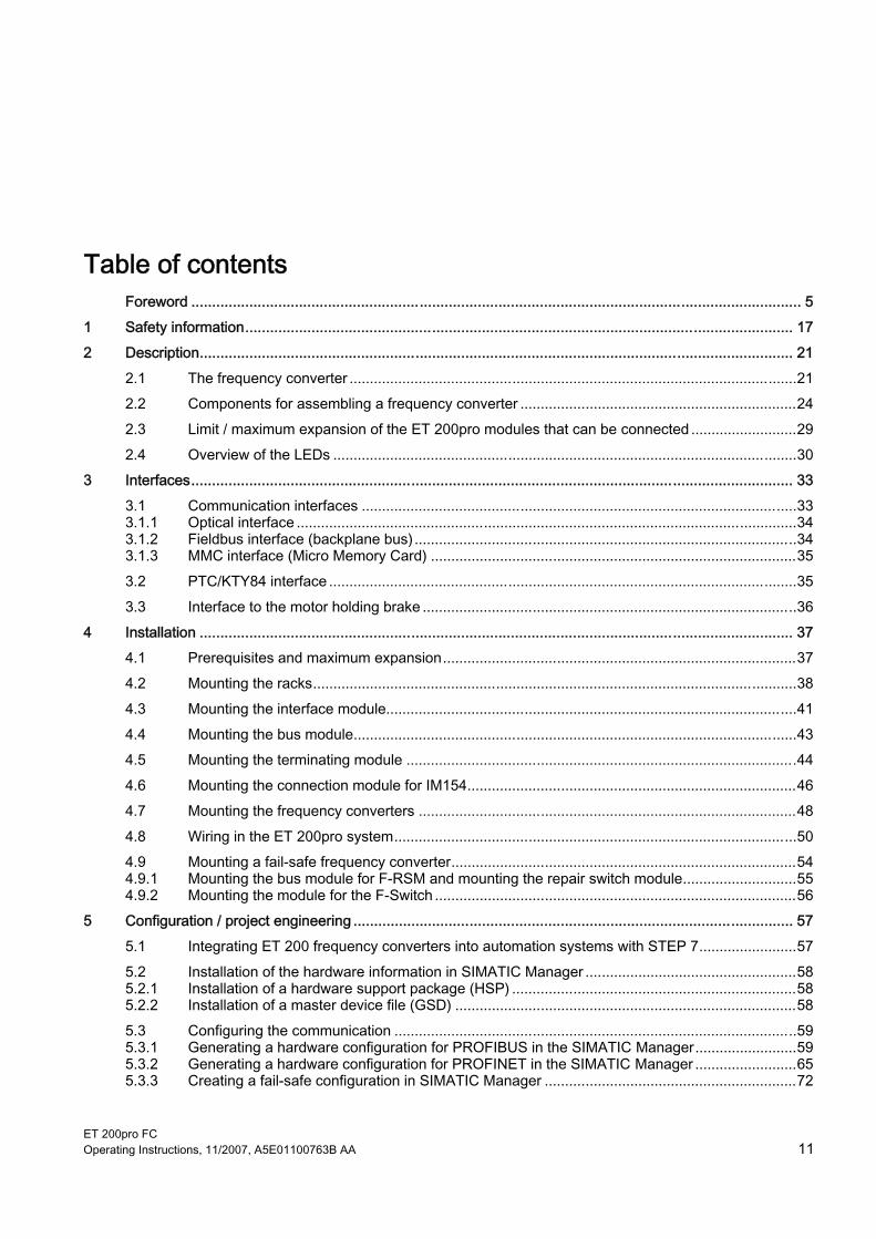
ET 200pro FC Operating Instructions, 11/2007, A5E01100763B AA 11
Table of contents Foreword ................................................................................................................................................... 5 1 Safety information.................................................................................................................................... 17 2 Description............................................................................................................................................... 21
2.1 The frequency converter ..............................................................................................................21 2.2 Components for assembling a frequency converter ....................................................................24 2.3 Limit / maximum expansion of the ET 200pro modules that can be connected ..........................29 2.4 Overview of the LEDs ..................................................................................................................30
3 Interfaces................................................................................................................................................. 33 3.1 Communication interfaces ...........................................................................................................33 3.1.1 Optical interface ...........................................................................................................................34 3.1.2 Fieldbus interface (backplane bus)..............................................................................................34 3.1.3 MMC interface (Micro Memory Card) ..........................................................................................35 3.2 PTC/KTY84 interface ...................................................................................................................35 3.3 Interface to the motor holding brake ............................................................................................36
4 Installation ............................................................................................................................................... 37 4.1 Prerequisites and maximum expansion.......................................................................................37 4.2 Mounting the racks.......................................................................................................................38 4.3 Mounting the interface module.....................................................................................................41 4.4 Mounting the bus module.............................................................................................................43 4.5 Mounting the terminating module ................................................................................................44 4.6 Mounting the connection module for IM154.................................................................................46 4.7 Mounting the frequency converters .............................................................................................48 4.8 Wiring in the ET 200pro system...................................................................................................50 4.9 Mounting a fail-safe frequency converter.....................................................................................54 4.9.1 Mounting the bus module for F-RSM and mounting the repair switch module............................55 4.9.2 Mounting the module for the F-Switch .........................................................................................56
5 Configuration / project engineering .......................................................................................................... 57 5.1 Integrating ET 200 frequency converters into automation systems with STEP 7........................57 5.2 Installation of the hardware information in SIMATIC Manager ....................................................58 5.2.1 Installation of a hardware support package (HSP) ......................................................................58 5.2.2 Installation of a master device file (GSD) ....................................................................................58 5.3 Configuring the communication ...................................................................................................59 5.3.1 Generating a hardware configuration for PROFIBUS in the SIMATIC Manager.........................59 5.3.2 Generating a hardware configuration for PROFINET in the SIMATIC Manager .........................65 5.3.3 Creating a fail-safe configuration in SIMATIC Manager ..............................................................72

Table of contents
ET 200pro FC 12 Operating Instructions, 11/2007, A5E01100763B AA
6 Commissioning (hardware) ...................................................................................................................... 77 6.1 Startup of ET 200pro................................................................................................................... 78 6.2 Creating a drive configuration with STARTER............................................................................ 79
7 Commissioning and optimization (software) ............................................................................................ 83 7.1 Commissioning sequence........................................................................................................... 83 7.2 Commissioning and optimization of the frequency converter and motor combination ............... 85 7.2.1 General........................................................................................................................................ 85 7.2.2 Calculating the motor and controller data ................................................................................... 86 7.2.3 Motor Data Identification ............................................................................................................. 87 7.3 Commissioning and optimization of the drive application ........................................................... 91 7.4 Commissioning of communication between the S7 CPU and the frequency converter ............. 96 7.4.1 Parameter settings for communication ....................................................................................... 96 7.4.2 Process data transfer in the PROFIdrive profile ......................................................................... 98 7.4.2.1 Control and status words ............................................................................................................ 98 7.4.2.2 Examples................................................................................................................................... 101 7.4.3 Parameter transfer in the PROFIdrive profile............................................................................ 103 7.4.3.1 Block call ................................................................................................................................... 103 7.4.3.2 Examples................................................................................................................................... 109 7.5 Commissioning of the fail-safe functions .................................................................................. 115 7.5.1 General information on acceptance tests ................................................................................. 117 7.6 Performing a reset to factory settings ....................................................................................... 119 7.6.1 Factory settings......................................................................................................................... 120 7.6.2 Resetting fail-safe parameters to default values....................................................................... 121
8 Series commissioning and operation ..................................................................................................... 123 8.1 Transfer of the frequency converter parameter assignment..................................................... 124 8.1.1 Storage media for frequency converter parameters ................................................................. 124 8.1.2 Parameter transfer - Terms....................................................................................................... 125 8.1.3 Parameter transfer with MMC ................................................................................................... 126 8.1.4 Parameter transfer with PC (STARTER) .................................................................................. 129 8.1.5 Parameter transfer with PLC..................................................................................................... 130 8.1.6 Fault codes during upload and download ................................................................................. 131 8.2 Series commissioning and replacement of the frequency converter ........................................ 133 8.2.1 Application ID ............................................................................................................................ 133 8.2.2 Series commissioning ............................................................................................................... 134 8.2.3 Replacing a frequency converter .............................................................................................. 136 8.3 Operational performance of the converter ................................................................................ 137 8.4 Parameter change during operation ......................................................................................... 138
9 Alarm, fault, and system messages ....................................................................................................... 139 9.1 Fault codes and interrupts......................................................................................................... 139 9.2 Diagnostics through LEDs......................................................................................................... 140 9.3 Diagnostics through STARTER ................................................................................................ 143 9.4 Diagnostics through fieldbus..................................................................................................... 144 9.4.1 Diagnostics through the user program...................................................................................... 144 9.4.2 System diagnostics by means of standardized functions ......................................................... 144 9.5 Device diagnostics .................................................................................................................... 145
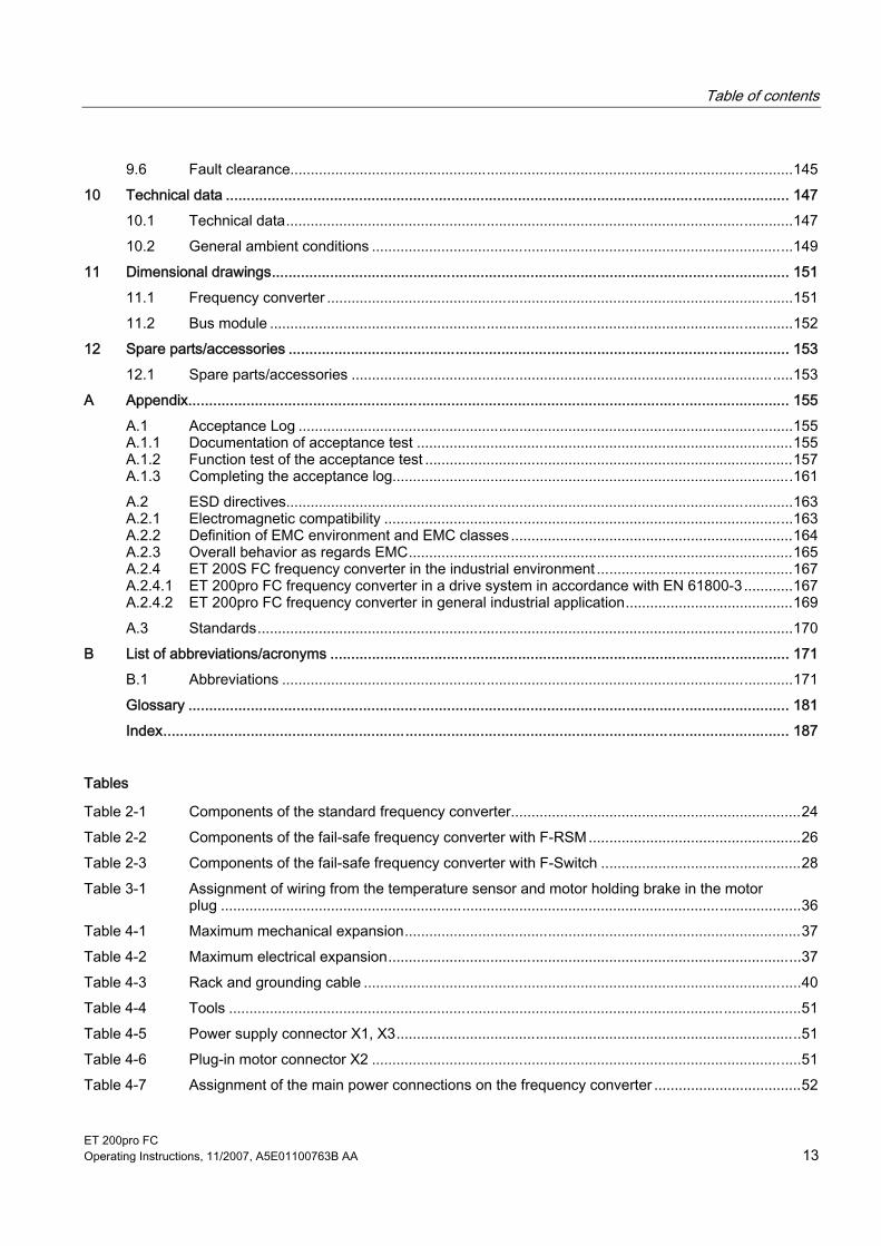
Table of contents
ET 200pro FC Operating Instructions, 11/2007, A5E01100763B AA 13
9.6 Fault clearance...........................................................................................................................145 10 Technical data ....................................................................................................................................... 147
10.1 Technical data............................................................................................................................147 10.2 General ambient conditions .......................................................................................................149
11 Dimensional drawings............................................................................................................................ 151 11.1 Frequency converter ..................................................................................................................151 11.2 Bus module ................................................................................................................................152
12 Spare parts/accessories ........................................................................................................................ 153 12.1 Spare parts/accessories ............................................................................................................153
A Appendix................................................................................................................................................ 155 A.1 Acceptance Log .........................................................................................................................155 A.1.1 Documentation of acceptance test ............................................................................................155 A.1.2 Function test of the acceptance test ..........................................................................................157 A.1.3 Completing the acceptance log..................................................................................................161 A.2 ESD directives............................................................................................................................163 A.2.1 Electromagnetic compatibility ....................................................................................................163 A.2.2 Definition of EMC environment and EMC classes .....................................................................164 A.2.3 Overall behavior as regards EMC..............................................................................................165 A.2.4 ET 200S FC frequency converter in the industrial environment ................................................167 A.2.4.1 ET 200pro FC frequency converter in a drive system in accordance with EN 61800-3............167 A.2.4.2 ET 200pro FC frequency converter in general industrial application.........................................169 A.3 Standards...................................................................................................................................170
B List of abbreviations/acronyms .............................................................................................................. 171 B.1 Abbreviations .............................................................................................................................171
Glossary ................................................................................................................................................ 181 Index...................................................................................................................................................... 187
Tables
Table 2-1 Components of the standard frequency converter.......................................................................24 Table 2-2 Components of the fail-safe frequency converter with F-RSM....................................................26 Table 2-3 Components of the fail-safe frequency converter with F-Switch .................................................28 Table 3-1 Assignment of wiring from the temperature sensor and motor holding brake in the motor
plug ..............................................................................................................................................36 Table 4-1 Maximum mechanical expansion.................................................................................................37 Table 4-2 Maximum electrical expansion.....................................................................................................37 Table 4-3 Rack and grounding cable ...........................................................................................................40 Table 4-4 Tools ............................................................................................................................................51 Table 4-5 Power supply connector X1, X3...................................................................................................51 Table 4-6 Plug-in motor connector X2 .........................................................................................................51 Table 4-7 Assignment of the main power connections on the frequency converter ....................................52

Table of contents
ET 200pro FC 14 Operating Instructions, 11/2007, A5E01100763B AA
Table 4-8 Power jumper connector ............................................................................................................. 53 Table 5-1 Operation with standard telegram 1............................................................................................ 59 Table 5-2 Standard telegram 1.................................................................................................................... 59 Table 6-1 Preconditions for commissioning ................................................................................................ 77 Table 7-1 First commissioning and optimization ......................................................................................... 84 Table 7-2 Standard commissioning............................................................................................................. 84 Table 7-3 STARTER connection options .................................................................................................... 85 Table 7-4 Settings for P0340....................................................................................................................... 87 Table 7-5 Standard telegram 1.................................................................................................................... 96 Table 7-6 Fieldbus parameters ................................................................................................................... 96 Table 7-7 Parameters for flexibly interconnecting process data in the PROFIdrive profile ........................ 97 Table 7-8 Preassignment, control word 1 ................................................................................................... 98 Table 7-9 Preassignment, status word 1................................................................................................... 100 Table 7-10 Parameter request .................................................................................................................... 104 Table 7-11 Parameter response.................................................................................................................. 105 Table 7-12 Description of the fields for parameter requests ....................................................................... 105 Table 7-13 Description of the fields for parameter requests ....................................................................... 107 Table 7-14 Error values in parameter responses........................................................................................ 108 Table 7-15 Parameters for fail-safe functions ............................................................................................. 116 Table 8-1 Settings of P8458 after an automatic parameter download from the MMC.............................. 128 Table 10-1 Technical data........................................................................................................................... 147 Table A-1 Machine description and overview/block diagram .................................................................... 155 Table A-2 Fail-safe functions for each drive .............................................................................................. 156 Table A-3 Description of the fail-safe equipment/devices ......................................................................... 157 Table A-4 "Safe Torque Off" function (STO).............................................................................................. 158 Table A-5 "Safe Stop 1" function (SS1) ..................................................................................................... 159 Table A-6 "Safely-Limited Speed" function (SLS) ..................................................................................... 160 Table A-7 Conductor-related and radiated emitted interference ............................................................... 165 Table A-8 EMC immunity........................................................................................................................... 166 Table A-9 Use in the industrial environment.............................................................................................. 167 Table A-10 Limit values for noise radiation for a drive system compliant with Category C3....................... 167 Table A-11 Limit values for interference immunity for a drive system compliant with Category C3 ........... 168 Table A-12 Ground leakage currents to EN 61800-5-1 with 15 m CY shielded cable ................................ 168 Table A-13 Limit values for noise radiation for general industrial application to EN 61000-6-4.................. 169 Table A-14 Limit values for interference immunity for general industrial application to EN 61000-6-2....... 169 Table 12-15 BICO parameter attributes ........................................................................................................ 183
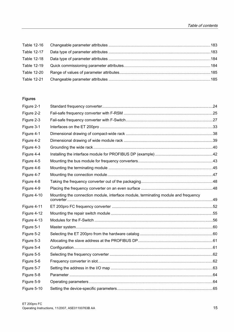
Table of contents
ET 200pro FC Operating Instructions, 11/2007, A5E01100763B AA 15
Table 12-16 Changeable parameter attributes ..............................................................................................183 Table 12-17 Data type of parameter attributes ..............................................................................................183 Table 12-18 Data type of parameter attributes ..............................................................................................184 Table 12-19 Quick commissioning parameter attributes................................................................................184 Table 12-20 Range of values of parameter attributes....................................................................................185 Table 12-21 Changeable parameter attributes ..............................................................................................185
Figures
Figure 2-1 Standard frequency converter......................................................................................................24 Figure 2-2 Fail-safe frequency converter with F-RSM ..................................................................................25 Figure 2-3 Fail-safe frequency converter with F-Switch................................................................................27 Figure 3-1 Interfaces on the ET 200pro ........................................................................................................33 Figure 4-1 Dimensional drawing of compact-wide rack ................................................................................38 Figure 4-2 Dimensional drawing of wide module rack ..................................................................................39 Figure 4-3 Grounding the wide rack ..............................................................................................................40 Figure 4-4 Installing the interface module for PROFIBUS DP (example) .....................................................42 Figure 4-5 Mounting the bus module for frequency converters.....................................................................43 Figure 4-6 Mounting the terminating module ................................................................................................45 Figure 4-7 Mounting the connection module.................................................................................................47 Figure 4-8 Taking the frequency converter out of the packaging..................................................................48 Figure 4-9 Placing the frequency converter on an even surface ..................................................................48 Figure 4-10 Mounting the connection module, interface module, terminating module and frequency
converter ......................................................................................................................................49 Figure 4-11 ET 200pro FC frequency converter .............................................................................................52 Figure 4-12 Mounting the repair switch module ..............................................................................................55 Figure 4-13 Modules for the F-Switch .............................................................................................................56 Figure 5-1 Master system..............................................................................................................................60 Figure 5-2 Selecting the ET 200pro from the hardware catalog ...................................................................60 Figure 5-3 Allocating the slave address at the PROFIBUS DP.....................................................................61 Figure 5-4 Configuration................................................................................................................................61 Figure 5-5 Selecting the frequency converter ...............................................................................................62 Figure 5-6 Frequency converter in slot..........................................................................................................62 Figure 5-7 Setting the address in the I/O map ..............................................................................................63 Figure 5-8 Parameter ....................................................................................................................................64 Figure 5-9 Operating parameters ..................................................................................................................64 Figure 5-10 Setting the device-specific parameters........................................................................................65

Table of contents
ET 200pro FC 16 Operating Instructions, 11/2007, A5E01100763B AA
Figure 5-11 Inserting an IO Controller ............................................................................................................ 66 Figure 5-12 Creating a network ...................................................................................................................... 66 Figure 5-13 Selecting the ET 200pro from the hardware catalog .................................................................. 67 Figure 5-14 Specifying device names ............................................................................................................ 67 Figure 5-15 Configuration............................................................................................................................... 68 Figure 5-16 Selecting the frequency converter .............................................................................................. 69 Figure 5-17 Frequency converter in slot......................................................................................................... 69 Figure 5-18 Setting the address in the I/O map ............................................................................................. 70 Figure 5-19 Parameter.................................................................................................................................... 71 Figure 5-20 Operating parameters ................................................................................................................. 71 Figure 5-21 Setting the device-specific parameters ....................................................................................... 72 Figure 5-22 Defining the start address ........................................................................................................... 73 Figure 5-23 Specifying the diagnostics properties ......................................................................................... 74 Figure 5-24 Configuring a frequency converter in a Safety Local environment ............................................. 74 Figure 5-25 Setting the PROFIsafe address 1018 by way of example .......................................................... 75 Figure 6-1 Starting up an ET 200pro with frequency converter ................................................................... 78 Figure 6-2 Power derating in relation to the ambient temperature............................................................... 79 Figure 6-3 Star connection/Delta connection conversion............................................................................. 81 Figure 7-1 Equivalent circuit diagram (ECD)................................................................................................ 88 Figure 7-2 Magnetizing characteristic........................................................................................................... 88 Figure 7-3 Writing PROFIdrive process data ............................................................................................. 102 Figure 7-4 Reading PROFIdrive process data ........................................................................................... 102 Figure 7-5 DB47 (DS47 write job) .............................................................................................................. 109 Figure 7-6 DB1 (DS47 response) ............................................................................................................... 110 Figure 7-7 Request processing in OB1 ...................................................................................................... 111 Figure 7-8 DB48 (DS47 read job)............................................................................................................... 112 Figure 7-9 DB1 (DS47 response) ............................................................................................................... 112 Figure 7-10 Example DB1 after P947 has been read out successfully with F70 pending (P947.0=70) ...... 114 Figure 8-1 Series commissioning interfaces .............................................................................................. 134 Figure 11-1 Standard frequency converters................................................................................................. 151 Figure 11-2 Bus module ............................................................................................................................... 152

ET 200pro FC Operating Instructions, 11/2007, A5E01100763B AA 17
Safety information 1Safety instructions
The warnings, safety information and remarks that follow are intended to be used as both safety measures for users and as measures that can be put in place to avoid damage to the product or to components of the connected machines. The following section provides an overview of warnings, safety information and remarks that are generally applicable to any work involving the ET 200pro FC product: these are divided into general instructions and instructions for transportation and storage, commissioning, operation, repair, disassembly, and disposal. Particular warnings and danger notices, as well as remarks on certain actions, will be given at the beginning of each relevant chapter of these Operating Instructions. In all sections, these will be repeated or expanded upon at key points. Please read this information carefully: it has been included with your own personal safety in mind and in order to help you extend the service life of both your ET 200pro FC product and the machines that are connected to it.
General information
WARNING
These devices carry hazardous voltages and control rotating mechanical parts which can be dangerous in some circumstances. Non-observance of the warnings or non-compliance with the instructions in this manual can lead to danger to life, serious injury or substantial damage to property. Protection by means of SELV/PELV in case of direct touching is permitted only in areas with equipotential bonding and in dry interior spaces. If these conditions are not fulfilled, other protective measures against electric shock are to be taken, e.g. protective insulation. Only suitably qualified personnel who have previously familiarized themselves with all the instructions regarding safety, installation, operating and maintenance as set out in this manual are permitted to work on these devices. Successful and safe operation of these devices depends on their proper handling, installation, operation and maintenance. If an RCD (also called ELCB or RCCB) has been installed, the power module works without switching-off inadvertently provided the following preconditions have been met: - A type B residual current operated circuit-breaker is used. - The response limit current of the RCD is 300 mA. - The neutral conductor of the network has been grounded. - Only one power module is supplied via each RCD. - The shielded output cables are shorter than 15 m.
Safety information
ET 200pro FC 18 Operating Instructions, 11/2007, A5E01100763B AA
The power-supply, direct-current and motor terminals as well as the brake cables and thermistor cables can carry hazardous voltages even when the converter is out of service. After interruption of the power supply, wait at least 5 minutes until the device has discharged itself. Only then carry out installation work. It is strictly forbidden to isolate the device from the supply on the motor side; isolation from the supply must always be carried out on the supply side of the converter. Before the power supply for the converter is connected, it must first be ensured that the terminal box of the motor has been connected. This device is designed to ensure internal motor-overload protection in accordance with UL508C. See P0610 and P0335; i²t has been set to ON as the standard setting. If an LED or similar indicator does not light up or is not active when a function is switched from ON to OFF, this does not mean that the unit has been switched off or is current-free. The converter must always be properly grounded. The device must be isolated from the power supply before any cables, plugs or wires are connected to the device or altered. Make sure that the converter has been configured for the correct supply voltage. It must be ensured that the converter is not connected to a higher supply voltage. Static discharge on surfaces or at interfaces which are not generally accessible (e.g. terminals or connector pins) can cause malfunctioning or defects. The ESD protective measures should therefore be observed during work with converters or converter components. The general and regional installation and safety regulations for working on equipment carrying hazardous voltages (e.g. EN 50178) as well as the relevant stipulations regarding the correct use of tools and personal protective equipment (PPE) are especially to be observed.
CAUTION Children and other unauthorized persons must be forbidden access to the devices! It is only permissible to use these devices for the purpose indicated by the manufacturer. Unauthorized changes and the use of spare parts and accessories which are not sold or recommended by the manufacturer of the device can lead to fires, electric shock and injuries.

Safety information
ET 200pro FC Operating Instructions, 11/2007, A5E01100763B AA 19
NOTICE
This manual is to be kept somewhere close to the devices and must be easily accessible for all users. If measurements or tests have to be carried out on the live device, the stipulations of safety regulation BGV A2 are to be complied with, especially § 8 "Permissible deviations during work on live parts". Suitable electronic tools are to be used. Before installation and commissioning, please read this safety information and the warnings carefully as well as the warning signs fitted to the devices. It must be ensured that the warning signs are always legible; any signs that are damaged or missing are to be replaced.
Transport and storage
WARNING Correct transport, storage as well as careful operation and maintenance are essential for the proper and safe operation of the equipment.
CAUTION
Protect the equipment against physical shocks and vibration during transport and storage. It is important that the equipment is protected from water (rainfall) and excessive temperatures.
Repairs
WARNING It is not permissible to open the frequency converter. If the frequency converter is nevertheless opened, a new one must be used in order to ensure retention of the same degree of protection.


ET 200pro FC Operating Instructions, 11/2007, A5E01100763B AA 21
Description 22.1 The frequency converter
Description The ET 200Pro FC is a compact frequency converter that is completely embedded in the distributed I/O system of the ET 200pro. The individual components can be configured in STEP 7 HW Config or integrated into other configuration systems using a GSD (device master file). The frequency converters are available in two versions: ● Standard ● Fail-safe The frequency converter works with an input voltage of 3 AC 400 V 50/60 Hz and can be used for 3-phase motors up to 1.1 KW, with temperature derating up to 1.5 KW.
Special features of the frequency converter The power unit of the frequency converter feeds the braking energy from the motor back into the line supply system. A braking resistor, which transforms energy accumulated during regenerative operation into heat, is not necessary. The frequency converter can be operated without a line reactor.
Commissioning and operation The commissioning software STARTER is used for commissioning. It can be downloaded from the Siemens homepage or ordered on a data carrier. It parameterizes the frequency converter through a fieldbus or a point-to-point connection. You have the option of reading the parameters for operating the frequency converter from the EEPROM of the frequency converter or from a Micro Memory Card (MMC) that is inserted in the frequency converter. A higher-level controller (e.g. SIMATIC S7) program is used to control the frequency converter.
Characteristics ● Compact frequency converter in the SIMATIC ET 200pro system ● Easy installation ● Easy commissioning ● Interconnection of signals using BICO technology ● Selectable data sets

Description 2.1 The frequency converter
ET 200pro FC 22 Operating Instructions, 11/2007, A5E01100763B AA
● Fast current limitation (FCL) for trip-free operation ● Energy recovery into line supply system ● No braking resistor required ● Robust EMC design ● Can be configured for a wide range of applications ● Powerfail-proof storage of parameter settings on either EEPROM or MMC ● Control and diagnostics using a higher-level controller (e.g. SIMATIC S7) ● Diagnostics through LEDs ● High pulse frequencies for low-noise motor operation (default setting: 4 kHz), can be set
between 2 kHz and 16 kHz ● Optical interface with USS protocol for commissioning with STARTER
Commissioning functions ● Quick commissioning ● Calculating the motor/controller data ● Motor data identification ● Application commissioning ● Series commissioning ● Parameter reset to default settings

Description 2.1 The frequency converter
ET 200pro FC Operating Instructions, 11/2007, A5E01100763B AA 23
Operating functions ● Adjustable setpoint channel ● Adjustable ramp function generator (RFG) ● Jog mode ● Free function blocks (FFB) ● Positioning ramp down ● Automatic restart (AR) function ● Flying restart ● Current limiting ● Slip compensation ● Motor holding brake (MHB) ● Regenerative braking Additional features of fail-safe frequency converters ● Safe Torque Off (STO) ● Safe Stop 1 (SS1) ● Safely Limited Speed (SLS)
Function modules ● Vector control (speed and torque control) without encoder ● V/f control with different characteristics
Protective functions ● Motor protection functions ● Frequency converter protection functions ● System protection functions
Interfaces ● PROFIBUS or PROFINET through backplane bus ● MMC as parameter memory ● Optical interface with USS protocol ● Motor temperature sensor PTC or KTY84 Additional features of fail-safe frequency converters Inputs for evaluating the switch-off signals from fail-safe ET 200pro modules (e.g. F-Switch or F-RSM)
Note These inputs are an interface to the backplane bus and not directly accessible.

Description 2.2 Components for assembling a frequency converter
ET 200pro FC 24 Operating Instructions, 11/2007, A5E01100763B AA
2.2 Components for assembling a frequency converter
General information The following section provides an overview of configuration options for the frequency converters in the ET 200pro distributed I/O system. Other general information on the ET 200pro distributed I/O system can be found in the manual entitled "ET 200pro Distributed I/O System". For the purpose of selecting the components of an ET 200pro distributed I/O system, we recommend the "SIMATIC ET 200 Configurator" tool. The ET 200pro system contains a large number of components which the user can combine according to his needs. The minimum configuration of a frequency converter requires a rack, a complete interface module including a bus terminating module (in the scope of supply of the IM), the bus module of the frequency converter and the frequency converter itself. The components described below represent the minimum configuration of a standard frequency converter. More information can be found on the ET 200pro website and in the general ET 200pro manual.
Standard frequency converter
Figure 2-1 Standard frequency converter
Table 2-1 Components of the standard frequency converter
Illustration Components Function 1 Rack, wide The ET 200pro bus modules, onto which the electronic modules are
screwed, must be mounted on the rack. Lengths: 0.5 m, 1 m
Description 2.2 Components for assembling a frequency converter
ET 200pro FC Operating Instructions, 11/2007, A5E01100763B AA 25
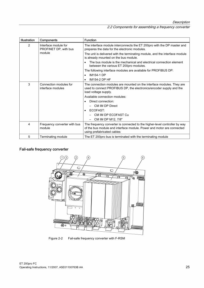
Illustration Components Function 2 Interface module for
PROFINET DP, with bus module
The interface module interconnects the ET 200pro with the DP master and prepares the data for the electronic modules. The unit is delivered with the terminating module, and the interface module is already mounted on the bus module. • The bus module is the mechanical and electrical connection element
between the various ET 200pro modules. The following interface modules are available for PROFIBUS DP: • IM154-1 DP • IM154-2 DP HF
3 Connection modules for interface modules
The connection modules are mounted on the interface modules. They are used to connect PROFIBUS DP, the electronics/encoder supply and the load voltage supply. Available connection modules: • Direct connection:
– CM IM DP Direct • ECOFAST:
– CM IM DP ECOFAST Cu – CM IM DP M12, 7/8"
4 Frequency converter with bus module
The frequency converter is connected to the higher-level controller by way of the bus module and interface module. Power and motor are connected using prefabricated cables
5 Terminating module The ET 200pro bus is terminated with the terminating module
Fail-safe frequency converter
Figure 2-2 Fail-safe frequency converter with F-RSM

Description 2.2 Components for assembling a frequency converter
ET 200pro FC 26 Operating Instructions, 11/2007, A5E01100763B AA
Table 2-2 Components of the fail-safe frequency converter with F-RSM
Illustration Components Function 1 Rack, wide The ET 200pro bus modules, onto which the electronic modules are
screwed, must be mounted on the rack. Lengths: 0.5 m, 1 m
2 Interface module for PROFINET DP, with bus module
The interface module interconnects the ET 200pro with the DP master and prepares the data for the electronic modules. The unit is delivered with the terminating module, and the interface module is already mounted on the bus module. • The bus module is the mechanical and electrical connection element
between the various ET 200pro modules. • The terminating module terminates the ET 200pro. The following interface modules are available for PROFIBUS DP: • IM154-1 DP • IM154-2 DP HF
3 Connection modules for interface modules
The connection modules are mounted on the interface modules. They are used to connect PROFIBUS DP, the electronics/encoder supply and the load voltage supply. Available connection modules: • Direct connection:
– CM IM DP Direct • ECOFAST:
– CM IM DP ECOFAST Cu – CM IM DP M12, 7/8"
Not illustrated
Interface module for PROFINET IO, with bus module
The interface module interconnects the ET 200pro with the IO controller and prepares the data for the electronic modules. The interface module and connection module are shipped as a compact unit. The terminating module is included. The interface module is mounted on the bus module. Interface module available for PROFINET IO: • IM154-4 PN HF
4 Safety Local repair switch module (F-RSM), with bus module
The F-RSM is used to trigger the safety functions of the fail-safe frequency converter through the backplane bus; it switches the power bus for the following motor starters and frequency converters. An F-RSM must always be plugged in the system to the left of the frequency converter and can be controlled only through local safe inputs (Safety Local function).
5 Frequency converter with bus module
The frequency converter is connected to the higher-level controller by way of the bus module and interface module; power and motor are connected using prefabricated cables
6 Terminating module The ET 200pro bus is terminated with the terminating module

Description 2.2 Components for assembling a frequency converter
ET 200pro FC Operating Instructions, 11/2007, A5E01100763B AA 27
Figure 2-3 Fail-safe frequency converter with F-Switch

Description 2.2 Components for assembling a frequency converter
ET 200pro FC 28 Operating Instructions, 11/2007, A5E01100763B AA
Table 2-3 Components of the fail-safe frequency converter with F-Switch
Illustration Components Function 1 Rack, wide The ET 200pro bus modules, onto which the electronic modules are
screwed, must be mounted on the rack. Lengths: 0.5 m, 1 m
2 Interface module for PROFINET DP, with bus module
The interface module interconnects the ET 200pro with the DP master and prepares the data for the electronic modules. The unit is delivered with the terminating module, and the interface module is already mounted on the bus module. • The bus module is the mechanical and electrical connection element
between the various ET 200pro modules. • The terminating module terminates the ET 200pro. The following interface modules are available for PROFIBUS DP: • IM154-1 DP • IM154-2 DP HF
3 Connection modules for interface modules
The connection modules are mounted on the interface modules. They are used to connect PROFIBUS DP, the electronics/encoder supply and the load voltage supply. Available connection modules: • Direct connection:
– CM IM DP Direct • ECOFAST:
– CM IM DP ECOFAST Cu – CM IM DP M12, 7/8"
Not illustrated
Interface module for PROFINET IO, with bus module
The interface module interconnects the ET 200pro with the IO controller and prepares the data for the electronic modules. The interface module and connection module are shipped as a compact unit. The terminating module is included. The interface module is mounted on the bus module. Interface module available for PROFINET IO: • IM154-4 PN HF
4 Fail-safe I/O module, with bus module F-Switch
The F-Switch is used in conjunction with the frequency converter only for the purpose of switching control signals from the higher-level controller through PROFIsafe onto the internal switch-off signals F0 and F1 on the ET 200pro backplane bus.
5 Frequency converter with bus module
The frequency converter is connected to the higher-level controller by way of the bus module and interface module. Power and motor are connected using prefabricated cables
6 Terminating module The ET 200pro bus is terminated with the terminating module
Description 2.3 Limit / maximum expansion of the ET 200pro modules that can be connected
ET 200pro FC Operating Instructions, 11/2007, A5E01100763B AA 29
2.3 Limit / maximum expansion of the ET 200pro modules that can be connected
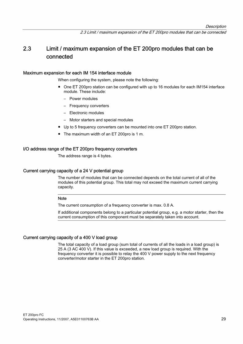
Maximum expansion for each IM 154 interface module When configuring the system, please note the following: ● One ET 200pro station can be configured with up to 16 modules for each IM154 interface
module. These include: – Power modules – Frequency converters – Electronic modules – Motor starters and special modules
● Up to 5 frequency converters can be mounted into one ET 200pro station. ● The maximum width of an ET 200pro is 1 m.
I/O address range of the ET 200pro frequency converters The address range is 4 bytes.
Current carrying capacity of a 24 V potential group The number of modules that can be connected depends on the total current of all of the modules of this potential group. This total may not exceed the maximum current carrying capacity.
Note The current consumption of a frequency converter is max. 0.8 A. If additional components belong to a particular potential group, e.g. a motor starter, then the current consumption of this component must be separately taken into account.
Current carrying capacity of a 400 V load group The total capacity of a load group (sum total of currents of all the loads in a load group) is 25 A (3 AC 400 V). If this value is exceeded, a new load group is required. With the frequency converter it is possible to relay the 400 V power supply to the next frequency converter/motor starter in the ET 200pro station.

Description 2.4 Overview of the LEDs
ET 200pro FC 30 Operating Instructions, 11/2007, A5E01100763B AA
2.4 Overview of the LEDs
Status display through LEDs The SIMATIC ET 200pro FC frequency converters have a number of functions and statuses that can be displayed by means of LEDs.
Standard frequency converter Fail-safe frequency converter
Colors The frequency converter status is displayed by means of the following range of LED colors and statuses:
Description Color Status On Off Transitional status
(Flashing: 0.5 Hz) Fault LED • SF
Red
Standby LED • RY
Green
Fail-safe LED • ES • STO, SS1, SLS
Yellow

Description 2.4 Overview of the LEDs
ET 200pro FC Operating Instructions, 11/2007, A5E01100763B AA 31
Description of the LEDs
LEDs Description System failure (SF) The "System failure" LED indicates a general system error in either
the software or hardware. Ready (RY) The Ready LED indicates whether the converter is ready; a control
word is sent for this purpose. It does not show whether the drive is running or not.
Final state (FS) The "Final state" LED shows whether the final state of a safety function that has been triggered has been reached.
Safe torque off (STO) The STO LED indicates the safety function "Safe Torque Off". Safe Stop 1 (SS1) The SS1 LED indicates the safety function "Safe Stop 1". Safely Limited Speed (SLS) The SLS LED indicates the safety function "Safely Limited Speed".
You can find safety function information in the Function Manual.
See also Diagnostics through LEDs (Page 140)


ET 200pro FC Operating Instructions, 11/2007, A5E01100763B AA 33
Interfaces 33.1 Communication interfaces
Overview The frequency converter has 3 communication interfaces. These are: ● An optical interface for commissioning the frequency converter using a PC and the
RS232 interface ● A fieldbus connection
Through the ET 200pro backplane bus for communicating with a higher-level control ● An MMC slot
Slot for a special micro memory card (MMC). The MMC can be used as a parameter memory or for updating firmware.
Figure 3-1 Interfaces on the ET 200pro
① Optical interface ② ET 200pro backplane bus ③ MMC

Interfaces 3.1 Communication interfaces
ET 200pro FC 34 Operating Instructions, 11/2007, A5E01100763B AA
3.1.1 Optical interface
Description The ET 200pro FC frequency converter has a serial optical communication interface with USS protocol for commissioning using the STARTER commissioning software on a PC. RS232/optical conversion is performed in the cable between the PC and the frequency converter. The following components are required: ● PC with Windows 2000/Windows 2003 Server/Windows XP ● STARTER commissioning software (version 4.1 or higher) ● RS232 interface cable (Order No. 6RK1 922-2PB00).
3.1.2 Fieldbus interface (backplane bus)
Description Communication between an ET 200pro station and the associated higher-level control (e.g. SIMATIC S7) is established using the standardized PROFIBUS DP communication protocol or PROFINET I/O. Communication within the ET 200pro system is performed over the ET 200pro backplane bus. The ET 200pro IM 154 interface module creates the interface between the two bus systems.
Communication data The ET 200pro FC frequency converter is operated and controlled in normal process mode via PROFIdrive profile 4.0 with standard telegram 1. The PROFIdrive profile with the standard telegram 1 provides the following functionality: ● Sending control words and setpoints with a fixed length to the drive ● Receiving status words and actual values with a fixed length from the drive ● Indicating drive faults through data record 47 ● Reading/writing parameters via data set 47.
Note Parameter values are transferred in acyclic data exchange through data record 47.
Standard diagnostics The frequency converter can be included in the standard diagnostics of S7.

Interfaces 3.2 PTC/KTY84 interface
ET 200pro FC Operating Instructions, 11/2007, A5E01100763B AA 35
3.1.3 MMC interface (Micro Memory Card)
Description The MMC interface can be used to back up frequency converter parameters on an external MMC and, if required, download them back onto the frequency converter.
Possible fields of application for the MMC The MMC can be used as a parameter memory: ● Uploading a parameter set onto an MMC ● Transferring parameters from an MMC when exchanging the frequency converter ● Automatic download of a parameter set from an MMC.
Note Several parameter sets can be stored on an MMC. The file name clone00.bin is used in the default setting. Other names can be set via P0804 (e.g., clone00.bin to clone99.bin).
Inserting the MMC
Precondition: The frequency converter must be disassembled. The label must be facing down when the chamfered edge of the MMC is pointing left. The MMC must be pushed into the MMC slot as far as it will go; it can only then be removed by pressing the eject button.
3.2 PTC/KTY84 interface The PTC/KTY84 interface can be used as an option.
Description The connection for a PTC/KTY84 sensor to the motor temperature monitor is integrated in the motor connector.
WARNING The motor temperature monitor is assigned to the line supply potential, dangerous touch voltages are thus possible. The frequency converter must be switched off-circuit before the motor temperature sensor can be connected.

Interfaces 3.3 Interface to the motor holding brake
ET 200pro FC 36 Operating Instructions, 11/2007, A5E01100763B AA
3.3 Interface to the motor holding brake
Description A motor holding brake can be controlled using the ET 200pro FC. The electrical connection between the frequency converter and the brake is established by plugging the motor cable into the frequency converter. Use of the motor holding brake is optional.
Table 3-1 Assignment of wiring from the temperature sensor and motor holding brake in the motor plug
Pin X2 on the frequency converter Number HAN Q8/0 (socket)
1 U 2 Not assigned 3 W 4 Brake (-) 5 PTC/KTY84 (+) 6 Brake (+) 7 V 8 PTC/KTY84 (-)
PE

ET 200pro FC Operating Instructions, 11/2007, A5E01100763B AA 37
Installation 44.1 Prerequisites and maximum expansion
Maximum mechanical expansion The maximum expansion of an ET 200pro is reached when one of the rules outlined below applies:
Table 4-1 Maximum mechanical expansion
Features Rule Number of modules max. 16 electronic modules Width of ET 200pro max. 1 m mounting width (without rack) Number of frequency converters maximum 5
Maximum electrical expansion ● Electronic / encoder supply 1L+:
– Powers the internal electronics of the frequency converters – Electrically isolated to the backplane bus of ET 200pro, to 2L+ and to
PROFIBUS DP/PROFINET IO ● Load voltage supply 2L+:
– Powers the safe inputs and outputs when a safety-orientated frequency converter is used
– Electrically isolated to the backplane bus, to 1L+ and to PROFIBUS DP/ PROFINET IO
Table 4-2 Maximum electrical expansion
Features Rule Electronic/encoder supply 1L+ max. 5 A per ET 200pro station; a frequency converter
requires 0.8 A Load voltage supply 2L+ max. 10 A per ET 200pro station
The load caused by the frequency converter is negligible
There is no electrical limit for a station that has been expanded with a maximum of 5 frequency converters.

Installation 4.2 Mounting the racks
ET 200pro FC 38 Operating Instructions, 11/2007, A5E01100763B AA
4.2 Mounting the racks The frequency converter is mounted on the wide rack. The following versions are possible: ● Rack, wide ● Rack, compact-wide
Dimensions
35
2727 11
922
023
1
35
2727 11
922
023
1
35
2727 11
922
023
1
182476
56
500
110
9
1312
9
13
1000
182 182976
5611
0
12
9
12
2000
max. 2001976
5611
0
12
182
Figure 4-1 Dimensional drawing of compact-wide rack

Installation 4.2 Mounting the racks
ET 200pro FC Operating Instructions, 11/2007, A5E01100763B AA 39
Figure 4-2 Dimensional drawing of wide module rack
Tools required ● Wrench or screwdriver, matching the selected fixing screws. ● Stripping tool and crimp tool for the grounding cable.
Installation 4.2 Mounting the racks
ET 200pro FC 40 Operating Instructions, 11/2007, A5E01100763B AA
Accessories required
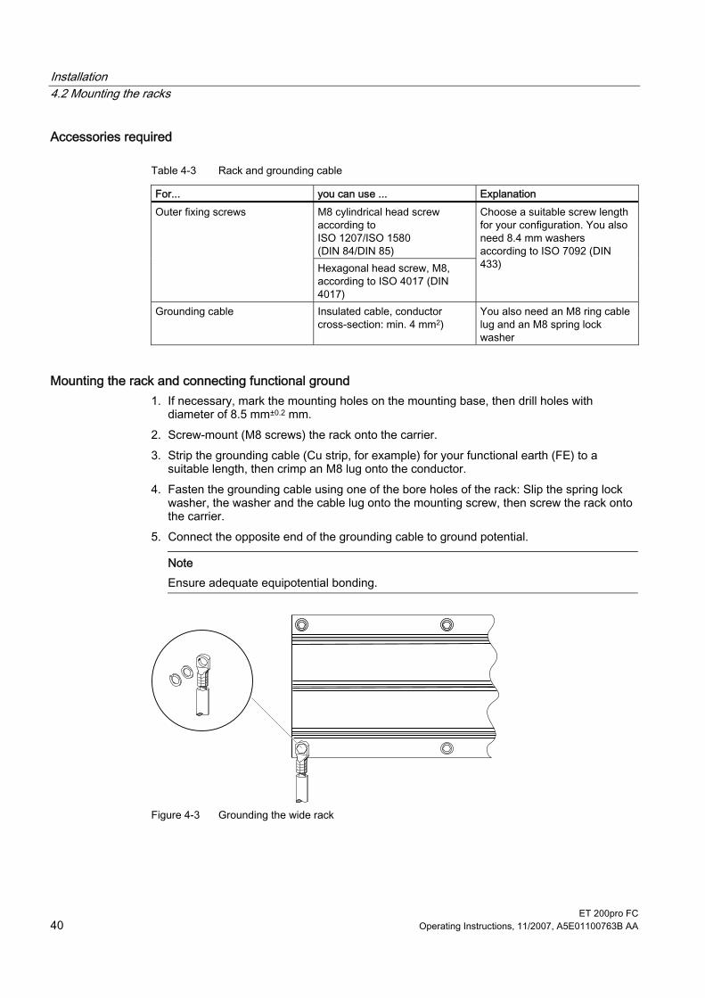
Table 4-3 Rack and grounding cable
For... you can use ... Explanation M8 cylindrical head screw according to ISO 1207/ISO 1580 (DIN 84/DIN 85)
Outer fixing screws
Hexagonal head screw, M8, according to ISO 4017 (DIN 4017)
Choose a suitable screw length for your configuration. You also need 8.4 mm washers according to ISO 7092 (DIN 433)
Grounding cable Insulated cable, conductor cross-section: min. 4 mm2)
You also need an M8 ring cable lug and an M8 spring lock washer
Mounting the rack and connecting functional ground 1. If necessary, mark the mounting holes on the mounting base, then drill holes with
diameter of 8.5 mm±0.2 mm. 2. Screw-mount (M8 screws) the rack onto the carrier. 3. Strip the grounding cable (Cu strip, for example) for your functional earth (FE) to a
suitable length, then crimp an M8 lug onto the conductor. 4. Fasten the grounding cable using one of the bore holes of the rack: Slip the spring lock
washer, the washer and the cable lug onto the mounting screw, then screw the rack onto the carrier.
5. Connect the opposite end of the grounding cable to ground potential.
Note Ensure adequate equipotential bonding.
Figure 4-3 Grounding the wide rack

Installation 4.3 Mounting the interface module
ET 200pro FC Operating Instructions, 11/2007, A5E01100763B AA 41
4.3 Mounting the interface module The interface module connects ET 200pro to PROFIBUS DP/ PROFINET IO and supplies power to the electronic modules.
Requirements ● Interface module for PROFIBUS DP
– The terminating module is removed from the interface module. – The rack has been mounted.
● Interface module for PROFINET IO – The terminating module is removed from the interface module. – The SIMATIC Micro Memory Card is inserted. – The rack has been mounted.
Required Tools Cross-tip screwdriver, size 2
Procedure 1. Snap-mount the Interface module onto the rack, then slide it into the correct position 2. Screw-mount the Interface module onto the rack.
Interface module for PROFIBUS DP (without connection module): 2 recessed head screws on the front: top and bottom, tightening torque 1.5 N/m Interface module for PROFINET IO: All recessed head screws on the front: top and bottom, tightening torque 1.5 N/m

Installation 4.3 Mounting the interface module
ET 200pro FC 42 Operating Instructions, 11/2007, A5E01100763B AA
Figure 4-4 Installing the interface module for PROFIBUS DP (example)
① Interface module

Installation 4.4 Mounting the bus module
ET 200pro FC Operating Instructions, 11/2007, A5E01100763B AA 43
4.4 Mounting the bus module The bus module connects the frequency converter to the ET 200pro backplane bus.
Requirements ● The interface module is mounted on the rack. ● Additional bus modules can be mounted next to the interface module
Procedure 1. Snap-mount the bus module onto the rack. 2. Push the bus module to the left until it engages into the interface module or the previous
electronic module.
Note The bus module is first screwed together with the frequency converter to the mounting plate.
Figure 4-5 Mounting the bus module for frequency converters
① Interface module ② Bus module 155 mm

Installation 4.5 Mounting the terminating module
ET 200pro FC 44 Operating Instructions, 11/2007, A5E01100763B AA
4.5 Mounting the terminating module The ET 200pro station must be terminated with the terminating module.
Requirements ● All bus modules are mounted on the rack.
Required tools Cross-tip screwdriver, size 2
Procedure 1. Mount the terminating module onto the rack. 2. Slide the terminating module to the left up against the last bus module.
Note Do not screw the terminating module to the rack (2 recessed head screws at the front, torque 1.5 Nm) until all the bus modules are mounted and screwed in place. The terminating module is included in the scope of delivery of the interface module.

Installation 4.5 Mounting the terminating module
ET 200pro FC Operating Instructions, 11/2007, A5E01100763B AA 45
Figure 4-6 Mounting the terminating module
① Interface module ② Bus module 155 mm ③ Bus terminating module
Installation 4.6 Mounting the connection module for IM154
ET 200pro FC 46 Operating Instructions, 11/2007, A5E01100763B AA
4.6 Mounting the connection module for IM154 There are various connection modules with different connection methods for IM 154 ● CM IM DP ECOFAST Cu ● CM IP DP M12, 7/8" ● CM IM DP Direct.
Requirements The interface module must be mounted.
Required tools Cross-tip screwdriver, size 2
Procedure 1. Make the settings depending on the connection module and establish the internal
connections The settings and connections of all communication modules are described in the manual "ET 200pro Distributed I/O Devices"
2. Fastening the connection module with 4 screws

Installation 4.6 Mounting the connection module for IM154
ET 200pro FC Operating Instructions, 11/2007, A5E01100763B AA 47
Figure 4-7 Mounting the connection module
① Connection module ② Interface module ③ Bus module 155 mm for frequency converters ④ Bus terminating module

Installation 4.7 Mounting the frequency converters
ET 200pro FC 48 Operating Instructions, 11/2007, A5E01100763B AA
4.7 Mounting the frequency converters The frequency converter is unpacked and screwed onto the bus module using 8 screws.
Note When removing the device from the packaging, be sure not to touch or damage the rear plug. Remove the device and place it on a even surface.
Figure 4-8 Taking the frequency converter out of the packaging
Figure 4-9 Placing the frequency converter on an even surface

Installation 4.7 Mounting the frequency converters
ET 200pro FC Operating Instructions, 11/2007, A5E01100763B AA 49
Requirements The bus module for the frequency converter and all the modules to the left are mounted.
Tools required Cross-head screwdriver, size 2.
Procedure 1. Plug the frequency converter into the bus module so that the two domes on the rear
engage in the guide holes of the bus module. 2. Holding the frequency converter firmly against the module rack, screw it in place with 4
screws on the top and 4 screws on the bottom. The upper 4 screws simultaneously fasten the bus module.
Figure 4-10 Mounting the connection module, interface module, terminating module and frequency
converter
① Connection module ② Interface module ③ Frequency converter ④ Bus terminating module

Installation 4.8 Wiring in the ET 200pro system
ET 200pro FC 50 Operating Instructions, 11/2007, A5E01100763B AA
4.8 Wiring in the ET 200pro system Communication and auxiliary voltages are routed with standard connectors through the interface module (or power modules) and the backplane bus to the frequency converter and do not have to be considered here. The power unit of the frequency converter is rated for direct operation on TN and TT line supply systems with a grounded PEN conductor with a rated voltage of 3 AC 400 V. In the case of systems where CE/EMC requirements are to be fulfilled, the prescribed shielded cables must be used. For this we recommend standard SY cables; the shield must be grounded at both ends and the perfect connection of the shielding must be checked. The 400 V supply is connected using standard connectors: ● X1 line supply system input ● X2 motor connector (the cables for both the brake and the temperature sensor are
integrated) ● X3 looped-through line supply system
Requirements
NOTICE
National Fire Protection Association (NFPA) compatibility These devices are only certified for installation in industrial machines in accordance with the "Electrical Standard for Industrial Machinery" (NFPA79). Due to their design features, it is possible that these devices cannot be installed in accordance with the National Electrical Code (NFPA70).
NOTICE
It is only permissible to use temperature-resistant copper cables for at least 75 °C.
● Motor cable: max. 15 m, shielded with metallic HAN 8 connector
A hybrid cable is necessary when using a motor holding brake and/or PTC/KTY 84. ● Additional incoming line supply system:
– If the 400 V infeed line, 4 mm² (AWG 12), is looped through within the ET 200 station; max. 25 A
– If a single infeed line is used for a frequency converter or motor starter, 1.5 mm² (AWG 16) is sufficient.
Installation 4.8 Wiring in the ET 200pro system
ET 200pro FC Operating Instructions, 11/2007, A5E01100763B AA 51
Tools required If you use prefabricated standard cables, no tools will be needed for the frequency converter side. You can adapt the motor side to your needs. If you want to prepare the cables yourself, the following tools, among others, will be needed.
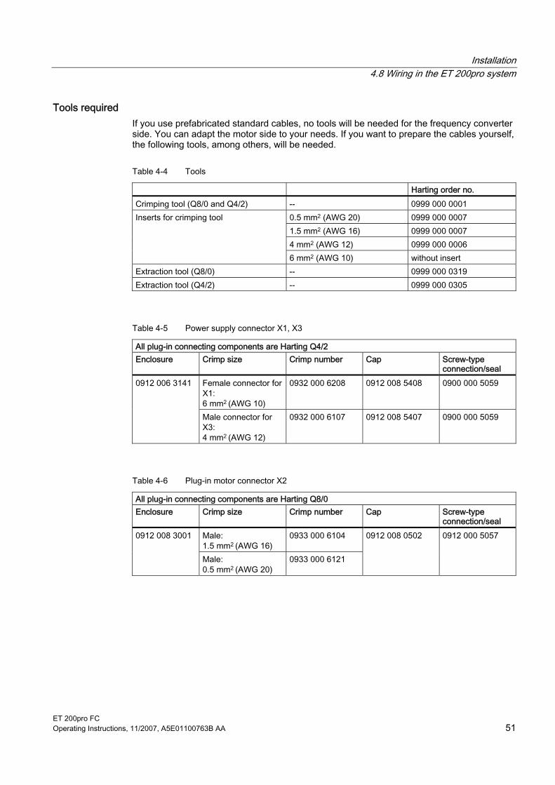
Table 4-4 Tools
Harting order no. Crimping tool (Q8/0 and Q4/2) -- 0999 000 0001
0.5 mm2 (AWG 20) 0999 000 0007 1.5 mm2 (AWG 16) 0999 000 0007 4 mm2 (AWG 12) 0999 000 0006
Inserts for crimping tool
6 mm2 (AWG 10) without insert Extraction tool (Q8/0) -- 0999 000 0319 Extraction tool (Q4/2) -- 0999 000 0305
Table 4-5 Power supply connector X1, X3
All plug-in connecting components are Harting Q4/2 Enclosure Crimp size Crimp number Cap Screw-type
connection/seal Female connector for X1: 6 mm2 (AWG 10)
0932 000 6208 0912 008 5408 0900 000 5059 0912 006 3141
Male connector for X3: 4 mm2 (AWG 12)
0932 000 6107 0912 008 5407 0900 000 5059
Table 4-6 Plug-in motor connector X2
All plug-in connecting components are Harting Q8/0 Enclosure Crimp size Crimp number Cap Screw-type
connection/seal Male: 1.5 mm2 (AWG 16)
0933 000 6104 0912 008 3001
Male: 0.5 mm2 (AWG 20)
0933 000 6121
0912 008 0502 0912 000 5057

Installation 4.8 Wiring in the ET 200pro system
ET 200pro FC 52 Operating Instructions, 11/2007, A5E01100763B AA
Figure 4-11 ET 200pro FC frequency converter
Table 4-7 Assignment of the main power connections on the frequency converter
Connection X1 Connection X2 Connection X3 Number HAN Q4/2 (male) HAN Q8/0 (female) HAN Q4/2 (female)
1 Phase L1 U Phase L1 2 Phase L2 Not assigned Phase L2 3 Phase L3 W Phase L3 4 Not assigned Brake (-) Not assigned 5 -- PTC/KTY84 (+) -- 6 -- Brake (+) -- 7 -- V -- 8 -- PTC/KTY84 (-) --
PE PE PE
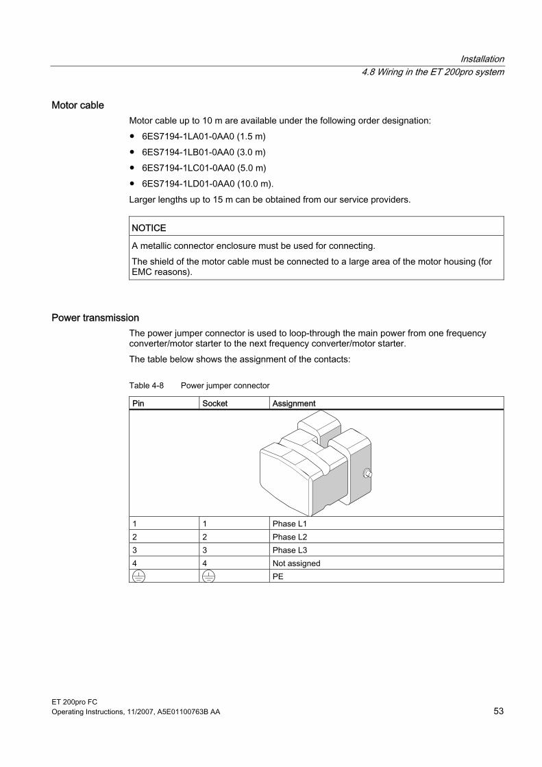
Installation 4.8 Wiring in the ET 200pro system
ET 200pro FC Operating Instructions, 11/2007, A5E01100763B AA 53
Motor cable Motor cable up to 10 m are available under the following order designation: ● 6ES7194-1LA01-0AA0 (1.5 m) ● 6ES7194-1LB01-0AA0 (3.0 m) ● 6ES7194-1LC01-0AA0 (5.0 m) ● 6ES7194-1LD01-0AA0 (10.0 m). Larger lengths up to 15 m can be obtained from our service providers.
NOTICE A metallic connector enclosure must be used for connecting. The shield of the motor cable must be connected to a large area of the motor housing (for EMC reasons).
Power transmission The power jumper connector is used to loop-through the main power from one frequency converter/motor starter to the next frequency converter/motor starter. The table below shows the assignment of the contacts:
Table 4-8 Power jumper connector
Pin Socket Assignment
1 1 Phase L1 2 2 Phase L2 3 3 Phase L3 4 4 Not assigned
PE
Installation 4.9 Mounting a fail-safe frequency converter
ET 200pro FC 54 Operating Instructions, 11/2007, A5E01100763B AA
4.9 Mounting a fail-safe frequency converter Fail-safe applications are configured basically the same as standard applications but with the following differences: ● Mounted to the left of the frequency converter must be a module through which the safety
functions of the frequency converter can be actuated, for example: – an F-RSM repair switch module – an F-Switch
● Only the following modules are allowed to be connected between the F-RSM or F-Switch and the fail-safe frequency converter: – 400 V shutdown module – all direct or reversing starters – the standard frequency converter – the fail-safe frequency converter
Procedure: Mount one after the other: 1. Rack 2. Interface module 3. Bus module for F-RSM or F-Switch 4. Bus module for frequency converter 5. Terminating module 6. Connection module for the interface module 7. F-RSM or F-Switch 8. Frequency converter

Installation 4.9 Mounting a fail-safe frequency converter
ET 200pro FC Operating Instructions, 11/2007, A5E01100763B AA 55
4.9.1 Mounting the bus module for F-RSM and mounting the repair switch module The Safety Local function of the F-RSM, its use, control elements and connections are described in detail in the manual SIMATIC ET 200pro Motor Starters. Therefore, only the most important points concerning its use with a frequency converter will be covered here. The 3RK 19222-BA01 bus module is required to accommodate a Safety Local repair switch module. It is mounted to the left of the frequency converter bus module. The Safety Local repair switch module is plugged onto its mounted backplane bus module (1) and screwed with 3 recessed head screws to the rack (2).
Note Make sure that the seal is cleanly seated and that the recessed head screws are tightened with a torque of 1.5 Nm to ensure a tight arrangement.
Figure 4-12 Mounting the repair switch module
Tools required Cross-tip screwdriver, size 2

Installation 4.9 Mounting a fail-safe frequency converter
ET 200pro FC 56 Operating Instructions, 11/2007, A5E01100763B AA
4.9.2 Mounting the module for the F-Switch The function, use, control elements and connections of the F-Switch are described in detail in the manual ET 200pro Distributed I/O Devices - Fail-safe Modules Therefore, only the most important points concerning its use with a frequency converter will be covered here. The 6ES7 xxxxxxx bus module is required to accommodate an F-Switch. It is mounted to the left of the frequency converter bus module. Then the electronic module and the connection module are mounted.
Procedure 1. Plug the electronic module onto the bus module. 2. Plug the connection module onto the old electronic module. 3. Use a screwdriver, size 2, to screw the connection module onto the electronic module
and bus module with the 2 recessed head screws using a tightening torque of 1.5 Nm.
Figure 4-13 Modules for the F-Switch
ET 200pro FC Operating Instructions, 11/2007, A5E01100763B AA 57
Configuration / project engineering 55.1 Integrating ET 200 frequency converters into automation systems with
STEP 7
General information on STEP 7 STEP 7 is the basic package for configuring and programming SIMATIC automation systems. It is part of the SIMATIC industry software. The STEP 7 basic package is available in several versions. "STEP 7 for applications running on SIMATIC S7 300/400" is required for integrating ET 200pro frequency converters. Additional information on STEP 7 is provided in the STEP 7 manuals.
Integrating frequency converters into SIMATIC S7 Frequency converters are integrated into the network of a SIMATIC S7 control system using STEP 7. Communication takes place either with the standardized communication protocol PROFIBUS DP or through PROFINET IO. In PROFIBUS, the SIMATIC automation device represents the master and the ET200pro station with the PROFIBUS interface module and other components (such as frequency converters or I/O modules) represents the slave. In PROFINET IO, the SIMATIC automation device is referred to as the IO controller and the ET 200pro station with PROFIBUS interface module and other components, e.g. frequency converters or IO modules, as the field device. Within the ET 200pro distributed I/O system, the frequency converter is contacted through the ET 200pro backplane bus.
Hardware components (SIMATIC and ET 200pro) ● SIMATIC S7 300 or SIMATIC S7 400 with integrated PROFIBUS DP/PROFINET IO
interface ● ET 200pro with interface module ● ET 200pro FC frequency converter
Software components (SIMATIC and ET 200pro) ● STEP 7 Version 5.2, Service Pack 1 or higher plus hardware support package (HSP).
The download takes place from HW Config in STEP 7. The correct link is preset there. ● Program library Drive ES
See also Components for assembling a frequency converter (Page 24)

Configuration / project engineering 5.2 Installation of the hardware information in SIMATIC Manager
ET 200pro FC 58 Operating Instructions, 11/2007, A5E01100763B AA
5.2 Installation of the hardware information in SIMATIC Manager
5.2.1 Installation of a hardware support package (HSP) The HSP (hardware support package) file defines the system environment of an ET 200pro station. To be able to configure an ET 200pro with the HW Config tool, the relevant HSP file must be installed first. ● To do this, open the SIMATIC tool HW Config and go to "Install HW updates" in the
"Options" menu. ● In the upper part of the window, select the source of the file (Internet or data carrier) and
click "Execute". A new window opens. The HSP files found are displayed in a drop-down list box. Select the "ET 200pro" HSP and click "Copy" or "Download". You can then close this window.
● The copied HSP files will now be available in the drop-down list box of the window that you initially opened. Select the HSP files to be installed from the list of available files in the archive folder and click "Install". All STEP 7 applications will be closed automatically and the selected HSP files installed.
The next time you open the HW Config tool, the ET 200pro station will be in the hardware catalog under PROFIBUS DP.
5.2.2 Installation of a master device file (GSD) The device description for the frequency converter is declared to HW Config in STEP 7 by installing the GSD (master device file) for use with PROFIBUS and the GSDML for use with PROFINET. If no HSP is installed for the frequency converter in the STEP 7 pack, or if the frequency converter is operated with a third party master, the device description for operation on PROFIBUS can be implemented by installing the GSD file. In this case the masks and the designation of the frequency converters differ from the S7 standard as described on the following page. The following example demonstrates how the GSD can be input into HW Config of the SIMATIC. ● Open the program "HW Config".
Close any projects which may be open there. ● Then select Options > Install GSD files in order to open the dialog box for installing GSD
files and click "Browse" to select the location of the GSD file. ● Then select the file you want from the list and click on the button "Install".
After the dialog is closed, the hardware configuration catalog is updated automatically and you can open your project.
● Install the GSD file in the required language (English, French, German, Italian, or Spanish) from the folder containing the relevant data.
● Selection of the telegram in the frequency converter is set using the parameter P0922 while the drive is commissioned. The receive telegram is in r2050[8] and the send telegram is set using the P2051[8] parameter.
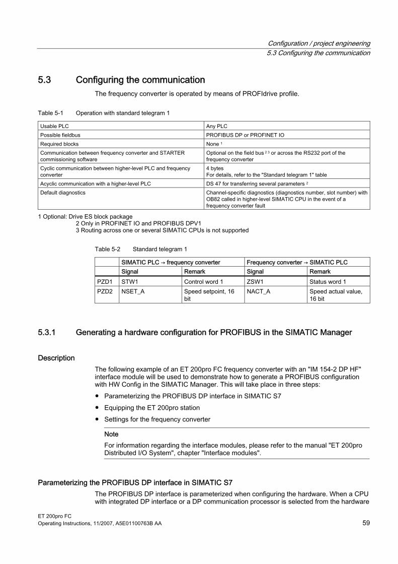
Configuration / project engineering 5.3 Configuring the communication
ET 200pro FC Operating Instructions, 11/2007, A5E01100763B AA 59
5.3 Configuring the communication The frequency converter is operated by means of PROFIdrive profile.
Table 5-1 Operation with standard telegram 1
Usable PLC Any PLC Possible fieldbus PROFIBUS DP or PROFINET IO Required blocks None 1 Communication between frequency converter and STARTER commissioning software
Optional on the field bus 2 3 or across the RS232 port of the frequency converter
Cyclic communication between higher-level PLC and frequency converter
4 bytes For details, refer to the "Standard telegram 1" table
Acyclic communication with a higher-level PLC DS 47 for transferring several parameters 2 Default diagnostics Channel-specific diagnostics (diagnostics number, slot number) with
OB82 called in higher-level SIMATIC CPU in the event of a frequency converter fault
1 Optional: Drive ES block package 2 Only in PROFINET IO and PROFIBUS DPV1 3 Routing across one or several SIMATIC CPUs is not supported
Table 5-2 Standard telegram 1
SIMATIC PLC → frequency converter Frequency converter → SIMATIC PLC Signal Remark Signal Remark PZD1 STW1 Control word 1 ZSW1 Status word 1 PZD2 NSET_A Speed setpoint, 16
bit NACT_A Speed actual value,
16 bit
5.3.1 Generating a hardware configuration for PROFIBUS in the SIMATIC Manager
Description The following example of an ET 200pro FC frequency converter with an "IM 154-2 DP HF" interface module will be used to demonstrate how to generate a PROFIBUS configuration with HW Config in the SIMATIC Manager. This will take place in three steps: ● Parameterizing the PROFIBUS DP interface in SIMATIC S7 ● Equipping the ET 200pro station ● Settings for the frequency converter
Note For information regarding the interface modules, please refer to the manual "ET 200pro Distributed I/O System", chapter "Interface modules".
Parameterizing the PROFIBUS DP interface in SIMATIC S7 The PROFIBUS DP interface is parameterized when configuring the hardware. When a CPU with integrated DP interface or a DP communication processor is selected from the hardware

Configuration / project engineering 5.3 Configuring the communication
ET 200pro FC 60 Operating Instructions, 11/2007, A5E01100763B AA
catalog, a PROFIBUS DP system is provided in the hardware configuration. After setting the parameters for the master, the slave – in this particular case the ET 200pro station – must be selected from the hardware catalog and placed on the PROFIBUS line. This is done by inserting an IM 154. The PROFIBUS address of the ET 200pro station must also be specified in IM 154.
Inserting a master system through the context menu of the CPU's DP interface
Figure 5-1 Master system
Inserting the ET 200pro system in the master system and specifying the PROFIBUS address
Figure 5-2 Selecting the ET 200pro from the hardware catalog

Configuration / project engineering 5.3 Configuring the communication
ET 200pro FC Operating Instructions, 11/2007, A5E01100763B AA 61
Figure 5-3 Allocating the slave address at the PROFIBUS DP
The configuration should now appear as follows:
Figure 5-4 Configuration

Configuration / project engineering 5.3 Configuring the communication
ET 200pro FC 62 Operating Instructions, 11/2007, A5E01100763B AA
Inserting a converter in an ET 200pro slot From the hardware catalog select "FC 1.1/1.5 kW; standard telegram 1" and pull it onto the slot.
Figure 5-5 Selecting the frequency converter
Figure 5-6 Frequency converter in slot
With this selection the user specifies which frequency converter will be used (standard or fail-safe).
Note When a fail-safe application is configured, an F-RSM or F-Switch must be connected in front of the frequency converter.
Settings for the frequency converter Double-clicking the frequency converter opens the property view with the following tabs: ● General ● Adresse ● Parameter.
Address/ID Setting an address in the I/O map The start address configured here is accepted in the user program as the "LADDR" input parameter for the blocks in the user program.

Configuration / project engineering 5.3 Configuring the communication
ET 200pro FC Operating Instructions, 11/2007, A5E01100763B AA 63
Figure 5-7 Setting the address in the I/O map
Note The input and output address area of the frequency converter must be the same.
Parameter The application ID provides a unique means of identification and is assigned by the user.
Note If the same application ID is entered for several frequency converters, they can be used interchangeably. Frequency converters with the same application ID must be parameterized in the same way. Only frequency converters with the same parameters may be used interchangeably.
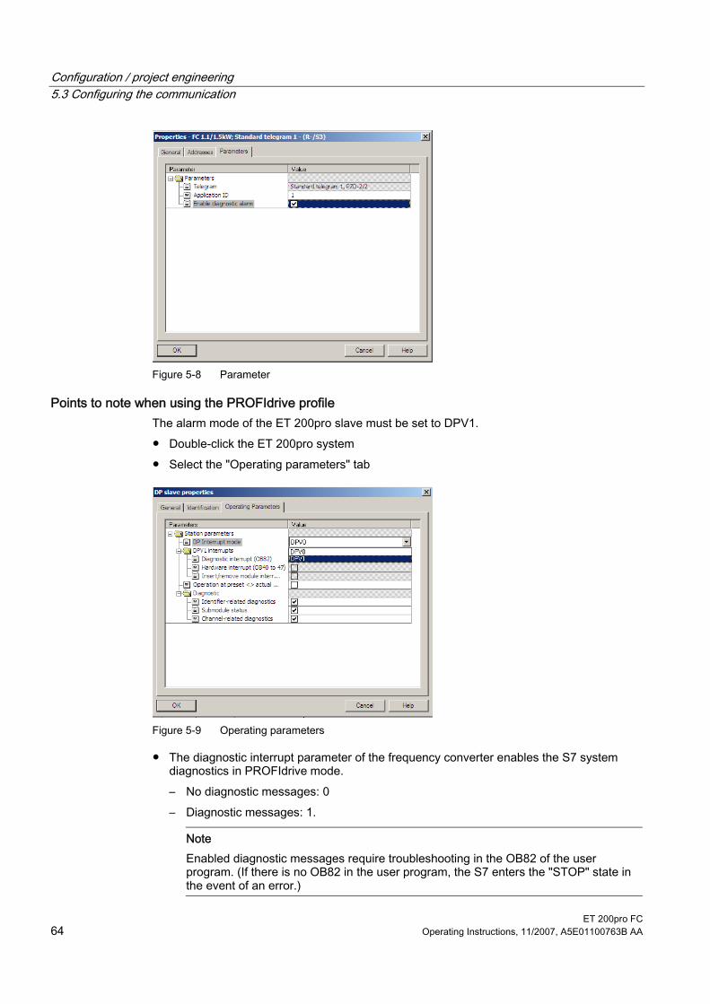
Configuration / project engineering 5.3 Configuring the communication
ET 200pro FC 64 Operating Instructions, 11/2007, A5E01100763B AA
Figure 5-8 Parameter
Points to note when using the PROFIdrive profile The alarm mode of the ET 200pro slave must be set to DPV1. ● Double-click the ET 200pro system ● Select the "Operating parameters" tab
Figure 5-9 Operating parameters
● The diagnostic interrupt parameter of the frequency converter enables the S7 system diagnostics in PROFIdrive mode. – No diagnostic messages: 0 – Diagnostic messages: 1.
Note Enabled diagnostic messages require troubleshooting in the OB82 of the user program. (If there is no OB82 in the user program, the S7 enters the "STOP" state in the event of an error.)

Configuration / project engineering 5.3 Configuring the communication
ET 200pro FC Operating Instructions, 11/2007, A5E01100763B AA 65
Figure 5-10 Setting the device-specific parameters
5.3.2 Generating a hardware configuration for PROFINET in the SIMATIC Manager
Description The following example of an ET 200pro FC frequency converter with an "IM 154-4 PN HF" interface module will be used to demonstrate how to generate a PROFINET configuration with HW Config in the SIMATIC Manager. This will take place in three steps: ● Parameterizing the PROFINET IO interface in SIMATIC S7 ● Equipping the ET 200pro station ● Settings for the frequency converter
Note Please refer to the "Interface modules" chapter in the manual entitled "ET 200pro Distributed I/O System" for information on the interface modules.
Parameterizing the PROFINET IO interface in SIMATIC S7 The hardware configuration is used to parameterize the PROFINET IO interface. When a CPU with an integrated DP interface or a DP communications processor is selected from the hardware catalog, a PROFINET IO system is made available in the hardware configuration. Once the parameters for the IO controller have been set, the slave - in this case, the ET 200pro station - must be selected from the hardware catalog and positioned on the PROFINET line. This is done by inserting an IM 154. The PROFINET address of the ET 200pro station must also be specified in IM 154.

Configuration / project engineering 5.3 Configuring the communication
ET 200pro FC 66 Operating Instructions, 11/2007, A5E01100763B AA
Inserting the IO controller using the context menu of the CPU PROFINET IO interface
Figure 5-11 Inserting an IO Controller
After the PROFINET IO system was inserted, a network must be created for it. In the context menu of the PN-IO click on "Object properties". In the window which then opens, click the "General" tab and then the "Properties" button to create a new network.
Figure 5-12 Creating a network

Configuration / project engineering 5.3 Configuring the communication
ET 200pro FC Operating Instructions, 11/2007, A5E01100763B AA 67
Inserting the ET 200pro system in the IO Controller
Figure 5-13 Selecting the ET 200pro from the hardware catalog
Specifying the device name In the PROFINET version, the address of the I/O devices is assigned via their device names. To do this, click the ET 200pro station in the HW Config tool to open its properties. You can then enter any unique device name you like.
Figure 5-14 Specifying device names

Configuration / project engineering 5.3 Configuring the communication
ET 200pro FC 68 Operating Instructions, 11/2007, A5E01100763B AA
The ET 200pro must then declare the name that has been selected. This can be performed in 2 different ways: ● Direct route --> The NameOfStation is written via PROFINET to the MMC of the IM in the
ET 200pro: The prerequisite for this is a PC with PG functionality, which can establish an Ethernet connection with the ET 200pro. An MMC must also be inserted in the IM. The name is assigned in the SIMATIC Manager. To do this, select the station to which a name is to be assigned via the "Target system > Edit Ethernet nodes.." menu entries in the window that appears. Use the "Browse" button in the "Ethernet nodes" field to do this. With an online connection to the station, all of the stations in the network that can be accessed appear in the window that opens. The relevant ET 200pro is selected by means of the MAC address and confirmed with "OK". In the "Assign device name" field, a name can be edited and assigned using the "Assign name" button. The NameOfStation can then be found on the MMC of the IM in the ET 200pro.
● Indirect route --> Written to the memory card with "Prommer": If no PC with PG functionality is available, or an online connection to the ET 200pro cannot be established, the device name can also be written to the MMC of the IM with the "Prommer" device. To do this, insert the MMC of the IM in the Prommer. Enable the ET 200pro in the HW Config tool and go to "Store device name on memory card" in the "Target system" menu. The prerequisite for this is that the desired "Device name" has been edited previously via the "Edit > Object properties.." menu entries. After the name has been successfully written to the MMC of the IM, this can then be inserted in the IM of the ET 200pro station. The configuration should now appear as follows:
Figure 5-15 Configuration
Inserting a converter in an ET 200pro slot

Configuration / project engineering 5.3 Configuring the communication
ET 200pro FC Operating Instructions, 11/2007, A5E01100763B AA 69
From the hardware catalog select "FC 1.1/1.5 kW; standard telegram 1" and pull it onto the slot.
Figure 5-16 Selecting the frequency converter
Figure 5-17 Frequency converter in slot
Settings for the frequency converter Double-clicking the frequency converter opens the property view with the following tabs: ● General ● Adresse ● Parameter.

Configuration / project engineering 5.3 Configuring the communication
ET 200pro FC 70 Operating Instructions, 11/2007, A5E01100763B AA
Address/ID Setting an address in the I/O map The start address configured here is accepted in the user program as the "LADDR" input parameter for the blocks in the user program.
Figure 5-18 Setting the address in the I/O map
Note The input and output address area of the frequency converter must be the same.
Parameter The application ID provides a unique means of identification and is assigned by the user.
Note If the same application ID is entered for several frequency converters, they can be used interchangeably. Frequency converters with the same application ID must be parameterized in the same way. Only frequency converters with the same parameters may be used interchangeably.

Configuration / project engineering 5.3 Configuring the communication
ET 200pro FC Operating Instructions, 11/2007, A5E01100763B AA 71
Figure 5-19 Parameter
Points to note when using the PROFIdrive profile The alarm mode of the ET 200pro slave must be set to DPV1. ● Double-click the ET 200pro system ● Select the "Operating parameters" tab
Figure 5-20 Operating parameters
● The diagnostic interrupt parameter of the frequency converter enables the S7 system diagnostics in PROFIdrive mode. – No diagnostic messages: 0 – Diagnostic messages: 1.
Note Enabled diagnostic messages require troubleshooting in the OB82 of the user program. (If there is no OB82 in the user program, the S7 enters the "STOP" state in the event of an error.)

Configuration / project engineering 5.3 Configuring the communication
ET 200pro FC 72 Operating Instructions, 11/2007, A5E01100763B AA
Figure 5-21 Setting the device-specific parameters
5.3.3 Creating a fail-safe configuration in SIMATIC Manager
Description A configuration is carried out using the fail-safe I/O module F-Switch or F-RSM on PROFIBUS DP. The procedure with PROFINET IO is similar and will not be described separately. Technical functions and the connections of the F-Switch and F-RSM are described respectively in the manual ET 200pro Distributed I/O Devices - Fail-safe Modules and in the manual SIMATIC-ET 200pro Motor Starters.
Requirements The following preconditions exist for the configuring and parameterizing of ET 200pro fail-safe modules: ● STEP 7 V 5.3 SP3 or higher ● S7 Distributed Safety V5.4 or higher (F Configuration Pack V5.5 SP1 or higher) ● S7 F systems V5.2 SP2 or higher The F Configuration Pack can be downloaded from the Internet (www.siemens.com/automation/service&support).
Procedure Once the IM154-2 HF has been positioned and parameterized in the master system, a module that can control the safety functions of the frequency converter using switch-off signals in the backplane bus is positioned to the left of the frequency converter. A fail-safe module (F-Switch or F-RSM) is then plugged in. Follow the usual procedure with STEP 7 HW Config to configure fail-safe modules (in the same way as standard ET 200pro modules).

Configuration / project engineering 5.3 Configuring the communication
ET 200pro FC Operating Instructions, 11/2007, A5E01100763B AA 73
Selection of F-Switch Selection of F-RSM The length of the process image of F-RSM is always one byte; only the start address must be set in the PI.
Figure 5-22 Defining the start address

Configuration / project engineering 5.3 Configuring the communication
ET 200pro FC 74 Operating Instructions, 11/2007, A5E01100763B AA
Group diagnostics can be activated or deactivated.
Figure 5-23 Specifying the diagnostics properties
You can use drag-and-drop to position the fail-safe frequency converter to the right of the F-Switch or F-RSM module. The configuration sequence is identical to the one used when generating a PROFIBUS configuration in the SIMATIC Manager.
Figure 5-24 Configuring a frequency converter in a Safety Local environment
Parameterizing module properties To parameterize fail-safe module properties, select the module in STEP 7 HW Config and select the menu command "Edit > Object properties". Parameters are downloaded from the programming device to the F-CPU, where they are stored and then transferred to the fail-safe module.

Configuration / project engineering 5.3 Configuring the communication
ET 200pro FC Operating Instructions, 11/2007, A5E01100763B AA 75
Parameter description The variable parameters of the fail-safe modules can be found in the manual entitled ET 200pro Distributed I/O Devices - Fail-Safe Modules.
PROFIsafe address and address assignment The PS address is set using a 10-pin DIP switch on the left-hand side of the module housing. When carrying out parameterization using the PG, the user must specify the PS address selected for the module in binary code format. This corresponds to the DIP switch setting and the module PS address.
Figure 5-25 Setting the PROFIsafe address 1018 by way of example
Note The switch positions 0000000000 and 1111111111 are not allowed!


ET 200pro FC Operating Instructions, 11/2007, A5E01100763B AA 77
Commissioning (hardware) 6Introduction
Hardware commissioning involves the ET 200pro station and the drive components. The following procedure describes by way of example the commissioning of a minimum configuration on PROFIBUS DP, with an S7 controller as the master and STARTER software directly on the optical interface of the frequency converter. It is assumed that the user has the necessary knowledge of STARTER to create a drive configuration and to use the operating panel.
Preconditions
Table 6-1 Preconditions for commissioning
Actions Reference ET 200pro is mounted Chap. Assembling PROFIBUS address is set on interface module and IM is wired
Interface module manual
ET 200pro is configured Chap. Planning/Configuring Motor is connected Chap. Assembling Power supply to the DP master is ON Manual for the DP master The DP master is set to RUN mode Manual for the DP master

Commissioning (hardware) 6.1 Startup of ET 200pro
ET 200pro FC 78 Operating Instructions, 11/2007, A5E01100763B AA
6.1 Startup of ET 200pro
Procedure Switch on the power supply for the ET 200pro station (electronics/encoder supply 1L+ for the ET 200pro).
Mode of operation The illustration below represents the startup routine of the ET 200pro with a frequency converter.
Figure 6-1 Starting up an ET 200pro with frequency converter

Commissioning (hardware) 6.2 Creating a drive configuration with STARTER
ET 200pro FC Operating Instructions, 11/2007, A5E01100763B AA 79
Note The SF LED on the S7 will not necessarily light up if an error occurs on the ET 200pro FC. The S7 receives notification of an error only if diagnostic messages are enabled in the converter. This is done via parameterization in HW Config. If diagnostic messages are disabled, errors in the converter can only be read by means of the red LED on the converter.
6.2 Creating a drive configuration with STARTER
Procedure ● Connect STARTER to the to the RS232 interface of the frequency converter. ● Generate a drive configuration; in doing so, check the motor data and take into account
the power derating in relation to the ambient temperature of the frequency converter.
°C 5 °C 10 °C 15 °C 20 °C 25 °C 30 °C 35 °C 40 °C 45 °C 50 °C 55 °C 60 °C
Figure 6-2 Power derating in relation to the ambient temperature

Commissioning (hardware) 6.2 Creating a drive configuration with STARTER
ET 200pro FC 80 Operating Instructions, 11/2007, A5E01100763B AA
Checking the motor terminal box (IEC/NEMA motor) For commissioning to be successful, it is important that the interconnection in the motor terminal box (see image below) corresponds to the entry for the rated motor voltage (P0304)/rated motor current (P0305).
IEC motor
Delta connection Star circuit configuration
E.g.: Voltage of 230 V (delta connection)/400 V (star connection)
NEMA motor Voltage U V W Connected to one another Circuit Low T1-T7 T2-T8 T3-T9 T4-T5-T6 Y Y High T1 T2 T3 T1-T7 T2-T8 T3-T9 Y
E.g.: Voltage of 230 V YY (low)/460 V Y (high) Voltage U V W Connected to one another Circuit Low T1-T6-T7 T2-T4-T8 T3-T5-T9 - ∆ ∆ High T1 T2 T3 T4-T7 T5-T8 T6-T9 ∆

Commissioning (hardware) 6.2 Creating a drive configuration with STARTER
ET 200pro FC Operating Instructions, 11/2007, A5E01100763B AA 81
Entering the type plate data The following should be noted when entering the type plate data/ESB data: ● The phase-to-phase voltage (voltage U12 between external lines L1 and L2) and/or
phase-to-phase current I1 is always specified on the type plate. ● The rated motor voltage (P0304)/rated motor current (P0305) must always be entered
according to the motor circuitry (delta/star). ● If the available rated motor data (P0304, P0305) are not consistent with the motor
circuitry, they should be converted before they are entered. ● If ESB data (P0350, P0354, P0356, P0358, P0360) is available, this should be entered
according to the motor circuitry. If the ESB data is not consistent with the motor circuitry, the ESB data should be converted before it is entered, in the same way as the data on the type plate (P0304, P0305).
Figure 6-3 Star connection/Delta connection conversion
Note The following formula can be used to check the accuracy of the motor type plate data:

ET 200pro FC Operating Instructions, 11/2007, A5E01100763B AA 83
Commissioning and optimization (software) 77.1 Commissioning sequence
The sequence in which the software of a frequency converter in an ET 200 station is commissioned depends on how complex the drive application is, and on the automation structure. The basic drive functions and the higher-level controller are commissioned first and are then specialized, optimized and the drive application generated. The parameters and settings that are located during this process can be used for standard commissioning, if required.
Requirements A prerequisite for software commissioning is functional hardware that has been commissioned according to the chapter entitled "Commissioning (hardware)". A drive configuration has been generated for the converter and the motor has been commissioned with the factory settings.
Procedure 1. First commissioning and optimization
– Frequency converter/motor combination – Drive application – Communication between the S7 CPU and frequency converter – Fail-safe functions
2. Standard commissioning Transferring the parameters and settings to other frequency converters
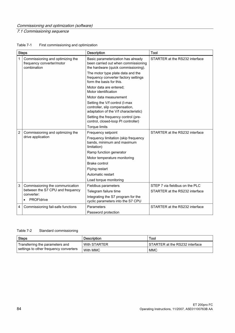
Commissioning and optimization (software) 7.1 Commissioning sequence
ET 200pro FC 84 Operating Instructions, 11/2007, A5E01100763B AA
Table 7-1 First commissioning and optimization
Steps Description Tool 1 Commissioning and optimizing the
frequency converter/motor combination
Basic parameterization has already been carried out when commissioning the hardware (quick commissioning). The motor type plate data and the frequency converter factory settings form the basis for this. Motor data are entered; Motor identification Motor data measurement Setting the V/f control (I-max controller, slip compensation, adaptation of the V/f characteristic) Setting the frequency control (pre-control, closed-loop PI controller) Torque limits
STARTER at the RS232 interface
2 Commissioning and optimizing the drive application
Frequency setpoint Frequency limitation (skip frequency bands, minimum and maximum limitation) Ramp function generator Motor temperature monitoring Brake control Flying restart Automatic restart Load torque monitoring
STARTER at the RS232 interface
3 Commissioning the communication between the S7 CPU and frequency converter: • PROFIdrive
Fieldbus parameters Telegram failure time Integrating the S7 program for the cyclic parameters into the S7 CPU
STEP 7 via fieldbus on the PLC STARTER at the RS232 interface
4 Commissioning fail-safe functions Parameters Password protection
STARTER at the RS232 interface
Table 7-2 Standard commissioning
Steps Description Tool With STARTER STARTER at the RS232 interface Transferring the parameters and
settings to other frequency converters With MMC MMC

Commissioning and optimization (software) 7.2 Commissioning and optimization of the frequency converter and motor combination
ET 200pro FC Operating Instructions, 11/2007, A5E01100763B AA 85
7.2 Commissioning and optimization of the frequency converter and motor combination
Description If there is still no matching parameter set for the drive, then quick commissioning including a motor data identification routine must be carried out - both for the closed-loop vector control and the V/f control. A PC with the STARTER commissioning software can be used for the quick commissioning. Once the quick commissioning has been completed, the frequency converter can put into operation. Before starting the quick commissioning, the following data must be queried, changed or entered: ● Enter the line frequency ● Enter the rating plate data ● Min./max. frequency or ramp-up/ramp-down time ● Control mode ● Motor data acquisition
7.2.1 General The frequency converter can be adapted to different applications by changing the parameter values.
Upload and download Upload is understood to mean the saving of parameters from the EEPROM of a frequency converter to a PC (using STARTER) or to an MMC. Download is understood to mean the transferring of a parameter set saved on a PC or an MMC into the RAM or EEPROM memory of a frequency converter. The commissioning procedure using STARTER is interactive and will not, therefore, be described in more detail here. STARTER can be connected locally to the frequency converter, or can access the fieldbus via the frequency converter.
Table 7-3 STARTER connection options
Type USS to RS232 Fieldbus PC connected to frequency converter via
RS232 interface cable Fieldbus cable
Restrictions Peer-to-peer Routing via SIMATIC CPU not possible

Commissioning and optimization (software) 7.2 Commissioning and optimization of the frequency converter and motor combination
ET 200pro FC 86 Operating Instructions, 11/2007, A5E01100763B AA
STARTER projects STARTER can be used to either create a new project or open an existing one. To create a new project in STARTER, any of the following procedures can be used: ● Find frequency converter ● Wizard ● Select frequency converter When an existing project is opened or a new one created, STARTER will be in offline mode. To go online, press the ("Connect to target system") button.
Changing parameters with STARTER Parameters can be changed online or offline (but preferably online). Parameter changes made online are stored in the RAM of the frequency converter. Transferring from RAM to the EEPROM can be triggered manually by pressing the ("Copy RAM to ROM") button. If the content of the RAM and EEPROM are different when the user closes STARTER, he/she will be asked if he/she wishes to transfer the data from the RAM to the EEPROM.
Note The storage method can be changed by means of P0014: • P0014=0: Parameter changes stored in RAM (default) • P0014=1: Parameter changes stored in EEPROM.
Parameter sets that have been changed offline can be transferred to the frequency converter using the download function ("Download project to target system").
CAUTION Parameters for safety functions can only be changed in online mode. Parameters for safety functions are not downloaded when parameters are downloaded using STARTER.
7.2.2 Calculating the motor and controller data The internal motor and controller data are calculated using the parameter P0340, or indirectly with the help of the parameter P3900 or P1910. The function of the parameter P0340 can be used, for example, if the data of the replacement circuit or the values of the moments of inertia are known.

Commissioning and optimization (software) 7.2 Commissioning and optimization of the frequency converter and motor combination
ET 200pro FC Operating Instructions, 11/2007, A5E01100763B AA 87
Table 7-4 Settings for P0340
P0340 Meaning 0 No calculation 1 Complete parameterization 2 Calculation of the replacement circuit data 3 Calculation of V/f and the closed-loop vector control 4 Calculation of the controller settings
For complete parameterization (P0340=1), not only the motor and controller parameters are assigned in advance but also the parameters which are related to the rated motor data (e.g. torque limit values and reference quantities for interface signals). The List Manual contains a full list of all parameters depending on P0340. For calculation of the motor and controller data with P0340 there are various scenarios which can be called up as a function of the known data.
7.2.3 Motor Data Identification
Description The Inverter has a measuring technique which is used to determine the motor parameters:
Equivalent circuit diagram (ECD) ➙ P1900 = 2 Measures Equivalent circuit diagram (ECD) + Magnetizing characteristic (includes P1900 = 2)
➙ P1900 = 3
For control-related reasons, it is essential that the motor data identification is performed. Without performing the motor data identification it is only possible to estimate ECD data using information from the motor rating plate. For example, the stator resistance is extremely important for the stability of the closed-loop Vector control and for the voltage boost of the V/f characteristic. The motor data identification routine should be executed, especially if long feeder cables or if third-party motors are being used. If the motor data identification routine is being started for the first time, then the following data is determined, starting from the rating plate data (rated [nominal] data) with P1900 = 2: ● ECD data ● Motor cable resistance ● IGBT on-state voltage and compensation of IGBT gating dead times. The rating plate data represents the initialization values for the identification. This is the reason that it is necessary to have the correct input from the rating plate data when determining the data specified above.

Commissioning and optimization (software) 7.2 Commissioning and optimization of the frequency converter and motor combination
ET 200pro FC 88 Operating Instructions, 11/2007, A5E01100763B AA
Figure 7-1 Equivalent circuit diagram (ECD)
In addition to the ECD data, the motor magnetizing characteristic (see the figure above) can be determined using the motor data identification (P1900 = 3). If the motor-inverter combination is operated in the field-weakening range (which is above the nominal frequency of the motor), then this characteristic should be determined, especially when Vector control is being used. As a result of this magnetizing characteristic, the Inverter can, in the field-weakening range, accurately calculate the current which is generated in the field and in-turn achieve a higher torque accuracy.
Figure 7-2 Magnetizing characteristic
The motor data identification is carried-out with the motor at a standstill and it takes, including the data calculation per selection (P1900 = 2 or 3), between 20 seconds and 4 minutes to complete. While the motor data identification is active A0541 is displayed. The identification time depends on the motor and increases with its size (this takes approx. 4 min. for a 200 kW motor). The motor data identification routine must be carried-out with the motor in the cold condition so that the motor resistance values saved can be assigned to the parameter of the ambient temperature P0625. Only then is the correct temperature adaptation of the resistances possible during operation.
Commissioning and optimization (software) 7.2 Commissioning and optimization of the frequency converter and motor combination
ET 200pro FC Operating Instructions, 11/2007, A5E01100763B AA 89
The motor data identification routine operates with the results of the "Complete parameterization" P0340 = 1 or the motor equivalent diagram data which was last saved. The results become increasingly better the more times that the identification routine is executed (up to 3 times).
WARNING It is not permissible to carry-out the motor identification routine for loads which are potentially hazardous (e.g. suspended loads for crane applications). Before starting the motor data identification routine, the potentially hazardous load must be secured (e.g. by lowering the load to the floor or clamping the load using the motor holding brake). When starting the motor data identification routine, the rotor can move into a preferred position. This is more significant for larger motors.
Note
The equivalent circuit data (P0350, P0354, P0356, P0358, P0360) and the motor cable resistance (P0352) are entered as phase values. During the motor identification routine, the sum of the stator resistance (P0350) and the motor cable resistance (P0352) are determined. To get a correct stator resistance the cable resistance has to be set before the motor identification has been started. If the motor cable resistance is known, it should be entered into parameter P0352 before the motor data identification. The value of P0350 then will be changed in dependenccy of P0352 and is more precisely as the calculated value. It is not necessary to lock the motor rotor for the motor data identification routine. However, if it is possible to lock the motor rotor during the identification routine (i.e. by closing the motor holding brake), then this should be used to determine the equivalent circuit diagram data. The following formula can be applied to check the correctness of the motor rating plate data:PN = √3 ∗ VNΥ ∗ INΥ ∗ cosϕ ∗ η ≈ √3 ∗ VNΔ ∗ INΔ ∗ cosϕ ∗ η Where: PN rated motor power VN Υ, VN Δ rated motor voltage (star/delta) IN Υ, IN Δ rated motor current (star/delta) cosϕ power factor η efficiency Before starting the motor identification, the correct ambient temp value should be entered in P0625 (default 20°C).
If Problems occur during the identification run, for example, the current controller oscillates, then the rating plate data should be re-checked and an approximately correct magnetizing current P0320 entered. The motor data identification routine should then be re-started by calling P1900 = 2 or P1900 = 3. A step-by-step description is given in section "Quick Commissioning".

Commissioning and optimization (software) 7.2 Commissioning and optimization of the frequency converter and motor combination
ET 200pro FC 90 Operating Instructions, 11/2007, A5E01100763B AA
Parameter settings
WARNING The motor data identification routine MUST not be used for loads which are potentially hazardous (for example, suspended loads for crane applications). Before the motor data identification routine is started, the potentially hazardous load must be carefully secured (for example, by lowering the load to the floor or by clamping the load using the motor holding brake).
Parameter Description P0625 = … Ambient motor temperature (entered in °C)
The motor ambient temperature is entered at the instant that motor data is being determined (factory setting: 20 °C). The difference between the motor temperature and the motor ambient temperature P0625 must lie in the tolerance range of approx. ± 5 °C.
If not the motor must be allowed to cool down. P0010 = 0 Commissioning parameter filter*
Check if P0010 = 0 (Ready) P1900 = 3 Select motor data identification*
0: Disabled (default) 2: Identification of all parameters in standstill. 3: Identification of all parameters in standstill including saturation curve
ON command Start motor data identification Once P1900 ≠ 0, alarm A0541 is generated that states, the next ON command will initiate the motor data identification. When the ON Command is given, current flows through the motor and the rotor aligns itself. Note: When motor data identification is complete A0541 will be cleared and P1900 will be set to zero.
OFF1 In order to set the inverter into a defined state, an OFF1 command must be issued before the next step. With the OFF1 command the motor data identification is finished.

Commissioning and optimization (software) 7.3 Commissioning and optimization of the drive application
ET 200pro FC Operating Instructions, 11/2007, A5E01100763B AA 91
7.3 Commissioning and optimization of the drive application After the motor and converter combination is commissioned by quick commissioning, parameters must be adapted and set to suit the requirements of the specific application.
Note According to the factory setting, parameter changes are saved in the volatile memory (RAM) of the converter. One of the following options can be used for saving the changes to EEPROM: • Set P0014 = 1: all changes are then saved immediately to EEPROM • Trigger transfer from RAM to EEPROM via P0971 = 1
or via the STARTER button . The duration of the data transfer depends on the number of parameters changed. In some cases it can take up to 3 minutes. When using STARTER, the transfer is indicated by a progress bar. A dialog field announces when transfer is successful.
The List Manual contains detailed parameter descriptions.
General settings Parameters Description (parameter name and factory setting in bold) Setting P0290 = 2 Converter overload behavior
Specifies the converter's response to internal overheating. 0: Reduce output frequency 1: Shut down (F00004) 2: Reduce pulse frequency and output frequency 3: Reduce pulse frequency, then shut down (F00004)
P0335 = 0 Motor cooling (enter the motor's cooling system) 0: Self-cooling using fan attached to the motor, mounted on the shaft 1: Separate cooling by means of a separately-driven cooling fan 2: Self-cooling and internal fan 3: Separate cooling and internal fan

Commissioning and optimization (software) 7.3 Commissioning and optimization of the drive application
ET 200pro FC 92 Operating Instructions, 11/2007, A5E01100763B AA
Temperature encoder Parameters Description (parameters and factory settings in bold) Setting P0601 = 0 or P0601 = …
Motor temperature encoder 0: No encoder (→ P0610) 1: PTC thermistor (→ P0604) 2: KTY84 (→ P0604)
P0604 = 130° Motor temperature limit Enter the alarm limit value of the motor overtemperature protection. The shutdown temperature (limit) is the value at which the converter will either shut down or Imax will be reduced (P0610); this always happens at 10% above the alarm limit value.
P0610 = 2 I2t temperature behavior of the motor (This defines the behavior of the motor if the temperature has reached the alarm limit value.) 0: No response, alarm only 1: Alarm and reduction of Imax (this results in a reduced output frequency) 2: Alarm and shutdown (F00011)
Temperature calculation without encoder Temperature calculation without a temperature encoder is possible in all operating modes. In vector mode the current temperature is determined automatically when the converter is switched on and the motor is hot. In V/f mode the motor temperature is set to an average value in this case.
Parameters Description (parameters and factory settings in bold) Setting P0621 = 1 Motor temperature measurement after restarting
0: No measurement. 1: Temperature measurement upon first power-up after an OFF/ON switching operation? 2: Temperature measurement after each power-up.
P0622 = … Motor remagnetizing time for temperature measurement after ON signal Length of a measuring cycle time for motor temperature measurement after ON signal Several measuring cycles are required to increase accuracy. This measuring cycle is pre-assigned the magnetizing time from the Mot ID (r0384)t.
Setting the frequency setpoint Parameters Description (parameter name and factory setting in bold) Setting P1000 = … Selecting the frequency setpoint
0: No master setpoint 6: Fieldbus (P2050 … P02091)

Commissioning and optimization (software) 7.3 Commissioning and optimization of the drive application
ET 200pro FC Operating Instructions, 11/2007, A5E01100763B AA 93
JOG frequency Parameter Description Setting P1057 = 1 JOG Enable
P1057 = 0 JOG-function disabled P1057 = 1 JOG-function enabled (default)
P1058 = 5 JOG frequency right Frequency in Hz when the motor is being jogged in the clockwise direction.
P1059 = 5 JOG frequency left Frequency in Hz when the motor is being jogged in the counter-clockwise direction.
P1060 = 45 JOG ramp-up time Ramp-up time in seconds from 0 to the maximum frequency (P1082). The JOG ramp-up is limited by P1058 or P1059.
P1061 = 50 JOG ramp-down time Ramp-down time in seconds from the maximum frequency (P1082) to 0.
Additional setpoints Parameters Description (parameter name and factory setting in bold) Setting P1074 = 1.0 BI: Disable additional setpoint P1075 = 775 CI: Additional setpoint
Specifies the source of the additional setpoint, which is added to the main setpoint.
P1076 = 1.0 CI: Additional setpoint scaling Defines the source for scaling the additional setpoint. General settings: 1: Scaling 1.0 (100%) 755: Analog input setpoint 1024: Fixed frequency setpoint 1050: MOP setpoint

Commissioning and optimization (software) 7.3 Commissioning and optimization of the drive application
ET 200pro FC 94 Operating Instructions, 11/2007, A5E01100763B AA
Skip Frequency Parameter Description Setting P1091 = 7.5 Skip frequency 1 (entered in Hz)
Avoids mechanical resonance effects and suppresses (skips) frequencies in the range around the skip frequency ± P1101 (skip frequency bandwidth).
P1092 = 0.0 Skip frequency 2 P1093 = 0.0 Skip frequency 3 P1094 = 0.0 Skip frequency 4 P1101 = 1.0 Skip frequency bandwidth (entered in Hz)
Ramp times Parameter Description Setting P1120 = 10 Ramp-up time
Enter the acceleration time in seconds.
P1121 = 10 Ramp-down time Enter the deceleration time in seconds.
Rounding Parameter Description Setting P1130 = 5.0 Ramp-up initial rounding time (in seconds) P1131 = 5.0 Ramp-up final rounding time (in seconds) P1132 = 5.0 Ramp-down initial rounding time (in seconds) P1133 = 5.0 Ramp-down final rounding time (in seconds) P1134 = 0 Rounding type
0: continuous smoothing (jerk-free) 1: Discontinuous smoothing NOTE: for discontinuous rounding (P1134 = 1), after the setpoint is reduced or an OFF1 command, the final rounding at ramp-up (P1131) and the initial rounding at ramp-down (P1132) are not executed.
The rounding times are recommended, to avoid abrupt responses and so to minimize stress to the mechanical system. The ramp-up and ramp-down times are extended by the component of the rounding ramps.

Commissioning and optimization (software) 7.3 Commissioning and optimization of the drive application
ET 200pro FC Operating Instructions, 11/2007, A5E01100763B AA 95
Parameters which must be set before ending the application settings The following parameters must be configured for every application.
Parameters Description (parameter name and factory setting (if non-variable) in bold print) Setting P1800 = 4 Pulse frequency (kHz)
The pulse frequency can be changed in steps of 2 kHz. The range extends from 2 kHz to 16 kHz. The full output current of the converter at 55 °C is 4 kHz. The highest output frequency is limited by the pulse frequency. With a pulse frequency of 2 kHz, operation up to 133 Hz is possible. If a higher output frequency is required, the pulse frequency should also be increased (10 kHz pulse frequency - maximum output frequency of 650 Hz). If no low-noise operation is required, then the converter losses and the high-frequency interference transmitted by the converter can be reduced by selecting a lower pulse frequency.
P2000 = 50 Reference frequency (Hz) The reference frequency in Hertz corresponds to a value of 100 %. This setting should be changed if a maximum frequency greater than 50 Hz is required. Comments: This scaling has an effect on the maximum frequency of the analog setpoints. Fixed frequencies and standardization processes of the motor potentiometer are related to 100 %.
P2001 = 1000 Reference voltage (V) The reference voltage in Volt (output voltage) corresponds to a value of 100 %. Comments: This setting should only be changed if the power must be output with a different scaling.
P2002 = ? Reference current (A) The reference current in Ampere (output current ) corresponds to a value of 100 %. The factory setting equals 200 % of the rated motor current (P0305). Comments: This setting should only be changed if the current must be output with a different scaling.
P2003 = ? Reference torque (Nm) The reference torque in Newton meter corresponds to a value of 100 %. The factory setting equals 200 % of the rated motor torque which is determined from the motor data for a constant motor torque. Comments: This setting should only be changed if the torque must be output with a different scaling.
P2004 = ? Reference power (kW or hp) The reference power in kW or hp corresponds to a value of 100 %. The factory setting is 200 % of the rated motor torque at constant motor torque. This setting should only be changed if the power must be output with a different scaling.
Ending the application settings Parameters Description (parameter name and factory setting (if non-variable) in bold print) Setting P0971 = 1 Adopting data from RAM into EEPROM
0: Inhibited 1: All parameter changes are transferred from RAM into EEPROM, i.e. the data are not lost if there is a power failure.

Commissioning and optimization (software) 7.4 Commissioning of communication between the S7 CPU and the frequency converter
ET 200pro FC 96 Operating Instructions, 11/2007, A5E01100763B AA
7.4 Commissioning of communication between the S7 CPU and the frequency converter
7.4.1 Parameter settings for communication The frequency converter is operated by means of PROFIdrive profile.
Table 7-5 Standard telegram 1
Telegram Function in the drive PZD1 PZD2 PZD3 PZD4 STW1 NSOLL_A 1
(PROFIdrive) Speed control 2 words
ZSW1 NIST_A ← Receive telegram from fieldbus → Send telegram to fieldbus
STW 1 Control word 1 ZSW 1 Status word 1 NSET_A (P1070) Speed setpoint A (16-bit) NIST_A (r0021) Speed setpoint A (16-bit)
Fieldbus parameter The following parameters must be set in order to put the fieldbus interface into operation:
Table 7-6 Fieldbus parameters
Parameter Contents P0700 Fast selection of command source P1000 Fast selection of frequency setpoint P2051 Actual values for process data (BICO) P2040 Failure time of process data telegram P0927 Parameter change source
P0700 and P1000 fast selection The control word and setpoint sources can be selected quickly in parameters P0700 (Select command source) and P1000 (Select frequency setpoint).
r2050 and P2051 BICO ● If process data is interconnected by means of binectors/connectors, much greater
flexibility is offered. ● The precise connection of setpoints and actual values from/to the fieldbus interface is
parameterized in r2050 and P2051.

Commissioning and optimization (software) 7.4 Commissioning of communication between the S7 CPU and the frequency converter
ET 200pro FC Operating Instructions, 11/2007, A5E01100763B AA 97
● The table below shows the parameters used to transfer process data in PROFIdrive mode.
Table 7-7 Parameters for flexibly interconnecting process data in the PROFIdrive profile
Telegram PZD1 STW/ZSW
PZD2 HSW/HIW
Connection values for setpoints, master to converter r2050.00 r2050.01 Connection parameters for actual values, converter to master P2051.00 P2051.01
Note r2050 also acts as a display parameter, by means of which the setpoint received from the fieldbus can be checked.
CAUTION The watchdog function must not be disabled. If this monitoring function is disabled and a fault occurs at the fieldbus interface, the converter cannot detect a fault condition and, therefore, continues to run even in the event of a fault.
Process data monitoring The telegram failure time is monitored in the converter using parameter P2040.
P2040 telegram failure time Parameter P2040 specifies the time after which a fault code (F0070) is generated if no telegram is received via the fieldbus. ● P2040 = 0 means: No monitoring ● P2040 > 0 means: The time in milliseconds after which a fault condition is generated if no
setpoint telegram has been received.
CAUTION
Faults can only trigger a shutdown if both monitoring functions are active.
If communication is taking place via the fieldbus, parameter P2040 should also be set to a value > 0. This enables/disables the process data monitoring function if the watchdog function is used on its own. The monitoring time corresponds to the watchdog time setting value, plus the time set in P2040.
Note Process data for which the complete control word (PZD1) is set to zero are not transferred to the converter via the fieldbus. Result: Fault F00070 may occur.

Commissioning and optimization (software) 7.4 Commissioning of communication between the S7 CPU and the frequency converter
ET 200pro FC 98 Operating Instructions, 11/2007, A5E01100763B AA
P0927 parameter change source
Bit Description Value 0 Fieldbus 0: No 1: Yes 2 Local interface 0: No 1: Yes
The factory setting for all bits is 1, i.e., the parameters can be changed from all sources.
7.4.2 Process data transfer in the PROFIdrive profile
7.4.2.1 Control and status words
Control word 1 (STW1) (Bits 0 to 10 according to PROFIdrive profile; bits 11 to 15 specifically for SIMATIC ET 200S FC and ET 200pro FC).
Table 7-8 Preassignment, control word 1
Bit Value Meaning Remarks 1 ON Puts the frequency converter into the "Ready to run"
state. The direction of rotation must be specified with bit 11.
0
0 OFF1 Shutdown, deceleration of ramp function generator ramp, pulse tripping when f < fmin.
1 Do not run down to standstill
All "Run down to standstill" (OFF2) commands are canceled.
1
0 Run down to standstill (OFF2)
Immediate pulse tripping; drive runs down to a standstill.
1 No rapid standstill All "Rapid standstill" (OFF3) commands are canceled. 2 0 Rapid standstill
(OFF3) Rapid stop: Shut down with the quickest possible delay rate.
1 Enable operation CL-control and frequency converter pulses are enabled.
3
0 Disable operation CL-control and frequency converter pulses are disabled.
1 Enable ramp function generator
-- 4
0 Reset ramp function generator
Ramp function generator output set to 0 (quickest possible deceleration); frequency converter remains in ON state.
1 Enable ramp function generator
-- 5
0 "Freeze" ramp function generator
The setpoint currently provided by the ramp function generator is "frozen".

Commissioning and optimization (software) 7.4 Commissioning of communication between the S7 CPU and the frequency converter
ET 200pro FC Operating Instructions, 11/2007, A5E01100763B AA 99
Bit Value Meaning Remarks 1 Enable setpoint The value selected on the ramp function generator
input is enabled. 6
0 Inhibit setpoint The value selected on the ramp function generator input is set to 0 (zero).
1 Acknowledge error Error acknowledged with a positive pulse edge; frequency converter then switches to the "Begin interlocking" state.
7
0 Not relevant -- 1 JOG 1 ON The drive runs up to the setpoint for jog mode as
quickly as possible (direction of rotation: clockwise). 8
0 JOG 1 OFF Drive brakes as quickly as possible. 1 JOG 2 ON The drive runs up to the setpoint for jog mode as
quickly as possible (direction of rotation: counter-clockwise).
9
0 JOG 2 OFF Drive brakes as quickly as possible. 1 Open-loop control
with PLC Open-loop control via interface; process data valid 10
0 No open-loop control with PLC
Process data invalid except for "sign of life"
1 Setpoint inversion Motor runs counter-clockwise as a response to a positive setpoint.
11
0 No setpoint inversion Motor runs clockwise as a response to a positive setpoint.
12 - Not used -- 13 - Not used -- 14 - Not used -- 15 1 Command data set bit
0 --
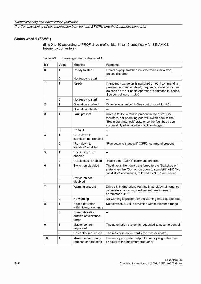
Commissioning and optimization (software) 7.4 Commissioning of communication between the S7 CPU and the frequency converter
ET 200pro FC 100 Operating Instructions, 11/2007, A5E01100763B AA
Status word 1 (ZSW1) (Bits 0 to 10 according to PROFIdrive profile; bits 11 to 15 specifically for SINAMICS frequency converters).
Table 7-9 Preassignment, status word 1
Bit Value Meaning Remarks 1 Ready to start Power supply switched on; electronics initialized;
pulses disabled. 0
0 Not ready to start -- 1 Ready Frequency converter is switched on (ON command is
present); no fault enabled; frequency converter can run as soon as the "Enable operation" command is issued. See control word 1, bit 0
1
0 Not ready to start -- 1 Operation enabled Drive follows setpoint. See control word 1, bit 3 2 0 Operation inhibited -- 1 Fault present Drive is faulty. A fault is present in the drive; it is,
therefore, not operating and will switch back to the "Begin start interlock" state once the fault has been successfully eliminated and acknowledged.
3
0 No fault -- 1 "Run down to
standstill" not enabled-- 4
0 "Run down to standstill" enabled
"Run down to standstill" (OFF2) command present.
1 "Rapid stop" not enabled
-- 5
0 "Rapid stop" enabled "Rapid stop" (OFF3) command present. 1 Switch-on disabled The drive is then only transferred to the "Switched on"
state when the "Do not run down to standstill" AND "No rapid stop" commands, followed by "ON", are issued.
6
0 Switch-on not disabled
1 Warning present Drive still in operation; warning in service/maintenance parameters; no acknowledgement; see interrupt parameter r2110.
7
0 No warning No warning is present, or the warning has disappeared.1 Speed deviation
within tolerance rangeSetpoint/actual value deviation within tolerance range. 8
0 Speed deviation outside of tolerance range
--
1 Master control requested
The automation system is requested to assume control.9
0 No control requested The master is not currently the master control. 10 1 Maximum frequency
reached or exceeded Frequency converter output frequency is greater than or equal to the maximum frequency.

Commissioning and optimization (software) 7.4 Commissioning of communication between the S7 CPU and the frequency converter
ET 200pro FC Operating Instructions, 11/2007, A5E01100763B AA 101
Bit Value Meaning Remarks 0 Maximum frequency
not reached --
1 -- -- 11 0 Warning: Motor
current/torque limit reached
--
1 Motor holding brake enabled
Signal can be used to control a holding brake. 12
0 -- -- 1 -- Motor data display overload status. 13 0 Motor overload -- 1 Clockwise rotation -- 14 0 Counter-clockwise
rotation --
1 -- -- 15 0 Converter overload For example, current or temperature
7.4.2.2 Examples
Writing PROFIdrive process data In this example, the control word STW1 and the setpoint frequency are written in PROFIdrive mode. The inputs E0.0 and E0.6 are linked to the Start/Stop bit or to the Acknowledge Fault bit of the control word STW1. The process data are written in the cyclical time slice of the S7 (e.g. OB1) at logical address 256 of the frequency converter.
Note Please note that the way cyclic data are interpreted depends on how the frequency converter is parameterized (P2050, P0922). Four bytes of process data are always transferred to the central control unit consistently. Use of the SFC14 and SFC15 is not necessary.

Commissioning and optimization (software) 7.4 Commissioning of communication between the S7 CPU and the frequency converter
ET 200pro FC 102 Operating Instructions, 11/2007, A5E01100763B AA
Figure 7-3 Writing PROFIdrive process data
Reading PROFIdrive process data In this example, status word 1 and the instantaneous frequency are read in PROFIdrive mode. The process data are read in the cyclical time slice of the S7 (e.g. OB1) from logical address 256 of the frequency converter.
Figure 7-4 Reading PROFIdrive process data

Commissioning and optimization (software) 7.4 Commissioning of communication between the S7 CPU and the frequency converter
ET 200pro FC Operating Instructions, 11/2007, A5E01100763B AA 103
Note Please note that the way cyclic data are interpreted depends on how the frequency converter is parameterized (P2051, P0922).
7.4.3 Parameter transfer in the PROFIdrive profile
7.4.3.1 Block call Acyclic data transfer can take place parallel to cyclic data transfer. The acyclic data transfer mode allows: ● Large quantities of user data (on PROFIBUS up to 240 bytes) to be exchanged ● Access through other PROFINET hosts (Class 2 masters, or in the case of PROFINET IO
by other IO controllers, e.g. commissioning tools) is possible.
Use of the expanded bus functions There are suitable channels available in the frequency converters for the different masters and IO controllers and for the different data transmission rates: ● Acyclic data exchange with the same master class of Class 1 or the same IO controller:
Use of the READ and WRITE functions. In this case, the content of the transferred data block corresponds to the structure of the non-cyclic parameter channel in accordance with the PROFIdrive profile, V4.0 (with data block 47 (DS47)).
● Acyclic data exchange with the help of a SIEMENS startup tool (master of Class 2 or supervisor) (e.g. STARTER). The startup tool can acyclically access parameters and process data in the frequency converter.
● Acyclic data exchange with a SIMATIC HMI (Human Machine Interface) (second master of Class 2 or second supervisor). The SIMATIC HMI can acyclically access parameters in the frequency converter.
● Instead of a SIEMENS commissioning tool or a SIMATIC HMI it is also possible for an external master (master of Class 2) or an external supervisor, as defined in the acyclic parameter channel according to the PROFIdrive profile, Version 4.0 (with DS47), to access the frequency converter.
Properties of the parameter channel ● One 16-bit address for each parameter number and subindex. ● Transfer of different parameters in one access (multiple request). ● Entire fields or parts of fields can be transferred. ● Only one parameter request is processed at a time (no pipelining). ● A parameter request/response must fit into a data set (on PROFIBUS: max. 240 bytes). ● The header of the task or the response are user data. ● Only 1 master or 1 supervisor on a frequency converter can be cyclically accessed at a
time.

Commissioning and optimization (software) 7.4 Commissioning of communication between the S7 CPU and the frequency converter
ET 200pro FC 104 Operating Instructions, 11/2007, A5E01100763B AA
Structure of parameter request and parameter response Each parameter request consists of three parts: Request header: ID for the request and number of parameters being accessed. Parameter address: Addressing a parameter. If multiple parameters are being accessed there will be a corresponding number of parameter addresses. The parameter address appears in the request and not in the response. Parameter value: For each parameter addressed there is a segment for the parameter values. Depending on the request ID, the parameter values appear either only in the request or in the response.
Table 7-10 Parameter request
Word Byte Byte Request reference Request ID Request header Drive object ID Qty Parameters Attribute Qty of elements Parameter number (PNU)
1. Parameter address
Subindex …
Attribute Qty of elements Parameter number (PNU)
n. parameter address
Subindex Format Qty Values Values
1. parameter value(s) (only in the case of "change parameters" request)
… …
Format Qty Values Values
n. parameter value(s)
…

Commissioning and optimization (software) 7.4 Commissioning of communication between the S7 CPU and the frequency converter
ET 200pro FC Operating Instructions, 11/2007, A5E01100763B AA 105
Table 7-11 Parameter response
Word Byte Byte Request reference mirrored Request ID Response header Drive object ID mirrored Qty Parameters Format Qty Values Values or error values
1. parameter value(s) (only after a "request")
… …
Format Qty Values Values or error values
n. parameter value(s)
…
Description of the fields for a parameter request and response
Table 7-12 Description of the fields for parameter requests
Field Data type Values Remark Unsigned 8 0x01 … 0xFF Request reference Unambiguous identification of the request/response pair for the master. The master changes the request reference with each new request. The slave mirrors the request reference in its response. Unsigned 8 0x01 0x02 Read request, write request Request ID Specifies the request type. In the event of a write request the changes are saved to volatile memory (RAM). A save operation is required in order to transfer the data to non-volatile memory (P0971). Unsigned 8 0x00 … 0xFF Number Drive object ID Setting for the drive object number with a drive unit with more than one drive object. Different drive objects with separate parameter number ranges can be accessed at the same DPV1 connection. Unsigned 8 0x01 … 0x27 No. 1 ... 39 Limited by the length of
the DPV1 telegram Qty Parameters
In the case of multiple requests, defines the number of adjacent areas for the parameter address and/or the parameter value for multiple parameter requests. The number of parameters = 1 for individual requests. Unsigned 8 0x10
0x20 0x30
Value Description Text (not implemented)
Attribute
Type of parameter element being accessed. Unsigned 8 0x00
0x01 … 0x75 Special function no. 1 ... 117 Limited by the length of the DPV1 telegram
Qty of elements
Number of field elements being accessed. Unsigned 16 0x0001 …
0xFFFF No. 1 … 65535 Parameter number
Number of parameter being accessed.
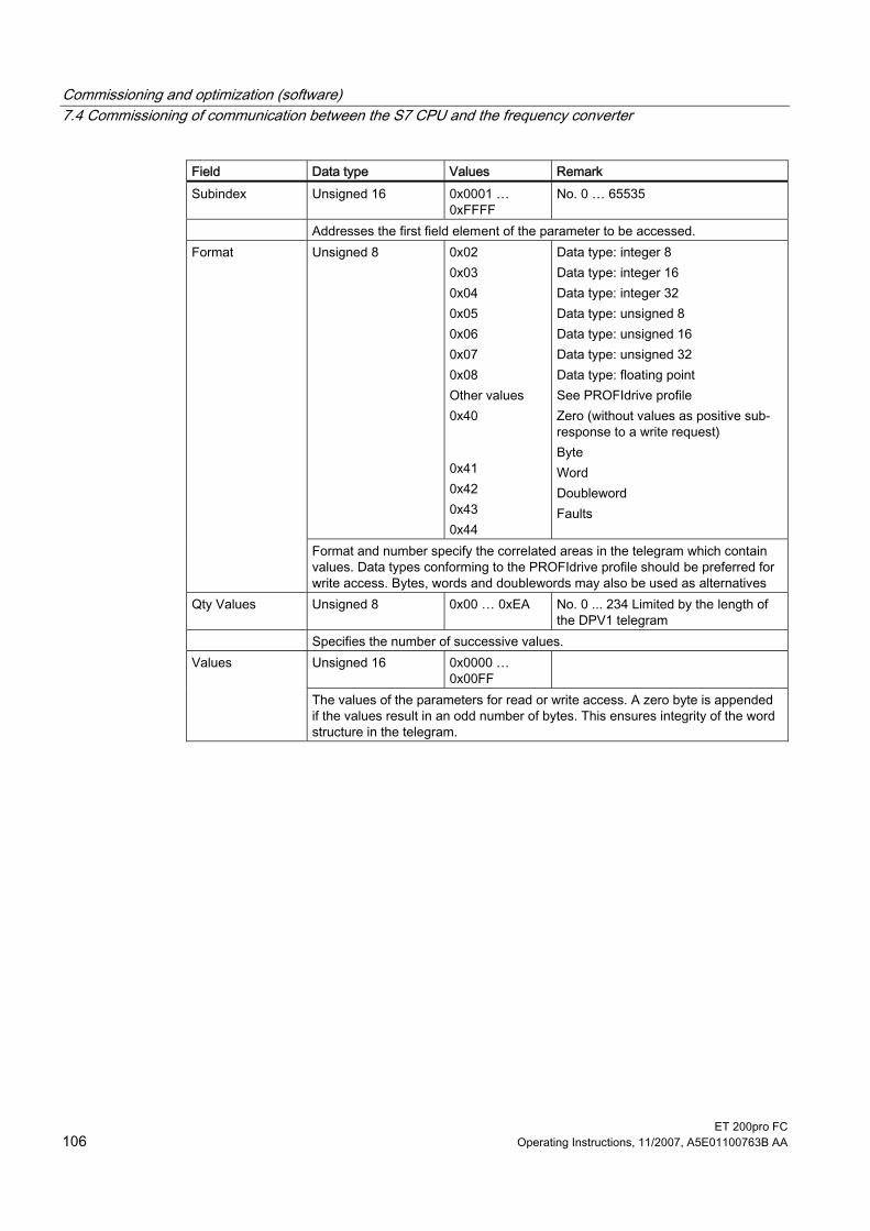
Commissioning and optimization (software) 7.4 Commissioning of communication between the S7 CPU and the frequency converter
ET 200pro FC 106 Operating Instructions, 11/2007, A5E01100763B AA
Field Data type Values Remark Subindex Unsigned 16 0x0001 …
0xFFFF No. 0 … 65535
Addresses the first field element of the parameter to be accessed. Unsigned 8 0x02
0x03 0x04 0x05 0x06 0x07 0x08 Other values 0x40 0x41 0x42 0x43 0x44
Data type: integer 8 Data type: integer 16 Data type: integer 32 Data type: unsigned 8 Data type: unsigned 16 Data type: unsigned 32 Data type: floating point See PROFIdrive profile Zero (without values as positive sub-response to a write request) Byte Word Doubleword Faults
Format
Format and number specify the correlated areas in the telegram which contain values. Data types conforming to the PROFIdrive profile should be preferred for write access. Bytes, words and doublewords may also be used as alternatives
Qty Values Unsigned 8 0x00 … 0xEA No. 0 ... 234 Limited by the length of the DPV1 telegram
Specifies the number of successive values. Unsigned 16 0x0000 …
0x00FF Values
The values of the parameters for read or write access. A zero byte is appended if the values result in an odd number of bytes. This ensures integrity of the word structure in the telegram.

Commissioning and optimization (software) 7.4 Commissioning of communication between the S7 CPU and the frequency converter
ET 200pro FC Operating Instructions, 11/2007, A5E01100763B AA 107
Table 7-13 Description of the fields for parameter requests
Field Data type Values Remark Request positive, status ok
Unsigned 8 0x01 0x02 0x81 0x82
Read request (+) Write request (+) Read request (–) Write request (–)
Request negative, error state
Request ID
Mirrors the request ID and indicates whether the execution of the request has been positive or negative. Negative means: part of the - or the entire request cannot be executed. The error values are transferred in place of the values for every sub-response.
Drive object ID See the table above Qty Parameters See the table above Format See the table above Qty Values See the table above Values See the table above
Unsigned 16 0x0000 … 0x00FF Meaning of the error values: See the next table
Error values
The error values in the event of a negative response. A zero byte is appended if the values result in an odd number of bytes. This ensures integrity of the word structure in the telegram.
Note The DRIVE-ES SIMATIC block package provides function blocks within the standard block libraries for writing/reading parameters, including a few examples.

Commissioning and optimization (software) 7.4 Commissioning of communication between the S7 CPU and the frequency converter
ET 200pro FC 108 Operating Instructions, 11/2007, A5E01100763B AA
Error values in parameter responses
Table 7-14 Error values in parameter responses
Error value
Meaning Remark Additional inf.
0x00 Invalid parameter number Access to a non-existent parameter. – 0x01 Parameter value cannot be
modified. Attempt to modify a read-only parameter.
Subindex
0x02 Low or high limit exceeded Attempted modification with value outside limits.
Subindex
0x03 Invalid subindex Access to non-existing subindex. Subindex 0x04 No field Access with subindex to non-indexed
parameter. –
0x05 Incorrect data type Attempt to modify with a value which is incompatible with the data type of the parameter.
–
0x06 Invalid "Set" action (only reset is allowed)
Attempt to modify with a value unequal 0 in a situation where this is not allowed.
Subindex
0x07 The descriptive element cannot be modified.
Attempt to modify a read-only descriptive element.
Subindex
0x09 No descriptive data Access to a non-existent description (parameter value exists).
–
0x0B No priority active Attempted modification without active priority.
–
0x0F No text field available Attempt to access a non-existent text field (parameter value exists).
–
0x11 Request cannot be executed on account of the operating state
Access is temporarily disabled for unspecified reasons.
–
0x14 Invalid value Attempt to modify with a value which lies within the limits, however, is invalid for other permanently valid reasons (parameters with permanently defined values).
Subindex
0x15 Response too long The length of the present response exceeds the maximum transfer length.
–
0x16 Invalid parameter address Invalid or unsupported value for attribute, number of elements, parameter number, subindex, or a combination of these.
–
0x17 Invalid format Write request for an invalid or unsupported parameter data format.
–
0x18 Inconsistent qty. of values Write request - The number of values in parameter data and the number of elements in the parameter address do not match.
–
0x19 Drive object is not present Access to a drive object which is not present.
–
0x20 The parameter text element cannot be modified.
Attempt to modify a read only parameter text element.
Subindex
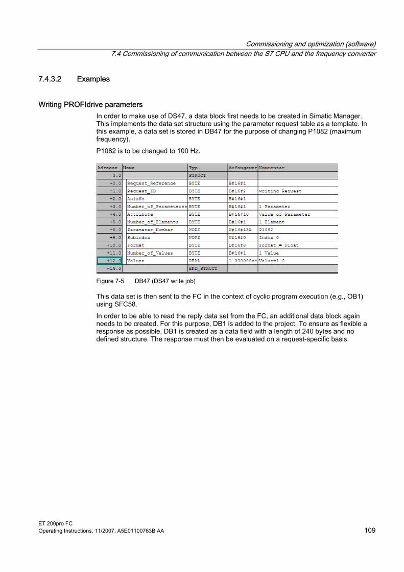
Commissioning and optimization (software) 7.4 Commissioning of communication between the S7 CPU and the frequency converter
ET 200pro FC Operating Instructions, 11/2007, A5E01100763B AA 109
7.4.3.2 Examples
Writing PROFIdrive parameters In order to make use of DS47, a data block first needs to be created in Simatic Manager. This implements the data set structure using the parameter request table as a template. In this example, a data set is stored in DB47 for the purpose of changing P1082 (maximum frequency). P1082 is to be changed to 100 Hz.
Figure 7-5 DB47 (DS47 write job)
This data set is then sent to the FC in the context of cyclic program execution (e.g., OB1) using SFC58. In order to be able to read the reply data set from the FC, an additional data block again needs to be created. For this purpose, DB1 is added to the project. To ensure as flexible a response as possible, DB1 is created as a data field with a length of 240 bytes and no defined structure. The response must then be evaluated on a request-specific basis.

Commissioning and optimization (software) 7.4 Commissioning of communication between the S7 CPU and the frequency converter
ET 200pro FC 110 Operating Instructions, 11/2007, A5E01100763B AA
Figure 7-6 DB1 (DS47 response)
Once the data blocks have been created, a parameter request is written via data set DS47 using S7 function SFC58. Then, a reply data set is read with SFC59 and stored in DB1. In this example, the start of this process is triggered by a positive edge at input In0.0.

Commissioning and optimization (software) 7.4 Commissioning of communication between the S7 CPU and the frequency converter
ET 200pro FC Operating Instructions, 11/2007, A5E01100763B AA 111
Figure 7-7 Request processing in OB1
Once the parameter request has been executed successfully, the request header (defined in DB47) must be mirrored in DB1 (requestID does not indicate any errors). To view the data currently stored in DB1, open DB1 in Simatic Manager and click the glasses icon. The parameter response table provides information about the structure of the reply data set.

Commissioning and optimization (software) 7.4 Commissioning of communication between the S7 CPU and the frequency converter
ET 200pro FC 112 Operating Instructions, 11/2007, A5E01100763B AA
Reading PROFIdrive parameters (example) In order to make use of DS47, a data block first needs to be created in SIMATIC Manager. The structure of the data set will then be implemented in it. In this example, a data set is stored in DB48 for the purpose of reading P0947 (error buffer).
Figure 7-8 DB48 (DS47 read job)
This data set is then sent to the FC in the context of cyclic program execution (e.g., OB1) using SFC58. In order to be able to read the reply data set from the FC, an additional data block needs to be created. For this purpose, DB1 is added to the project. To ensure as flexible a response as possible, DB1 is created as a data field with a length of 240 bytes and no defined structure. The response must then be evaluated on a request-specific basis.
Figure 7-9 DB1 (DS47 response)
Once the data blocks have been created, a parameter request is written via data set DS47 using S7 function SFC58. Then, a reply data set is read with SFC59 and stored in DB1. In this example, the start of this process is triggered by a positive edge at input In0.0.

Commissioning and optimization (software) 7.4 Commissioning of communication between the S7 CPU and the frequency converter
ET 200pro FC Operating Instructions, 11/2007, A5E01100763B AA 113

Commissioning and optimization (software) 7.4 Commissioning of communication between the S7 CPU and the frequency converter
ET 200pro FC 114 Operating Instructions, 11/2007, A5E01100763B AA
Figure 7-10 Example DB1 after P947 has been read out successfully with F70 pending (P947.0=70)

Commissioning and optimization (software) 7.5 Commissioning of the fail-safe functions
ET 200pro FC Operating Instructions, 11/2007, A5E01100763B AA 115
7.5 Commissioning of the fail-safe functions
General steps Those parameters that are marked with an asterisk ("*") offer a wider variety of setting options than the ones listed here. For information on additional setting options, please refer to the List Manual. When making changes to fail-safe functions, the following steps are mandatory:
Parameter Description Unit Standard
value Min. Max.
P0010 = 95 Commissioning parameter* 95: Commissioning of fail-safe functions
0 0 95
P9761 SI password input These parameters are used to enter the security password necessary for accessing and changing fail-safe function parameters.
- 0 1000 99999
Change the required fail-safe parameters and then follow the steps below to exit parameterization: P9799 Checksum for SI parameters
Checksum of fail-safe function parameters. Enter the value from r9798.
- 0000h 0000h FFFFh
P9899 Checksum for SI parameters Checksum of fail-safe function parameters. Enter the value from r9898.
- 0000h 0000h FFFFh
P3900 = 10 End of safety commissioning* 10: Accept changes to fail-safe function parameters. 11: Reject changes to fail-safe function parameters.
0 0 11
Parameters for fail-safe functions The table below provides an overview of all the fail-safe function parameters. Access level 3 applies in respect of the fail-safe parameters (P0003 = 3). The values of fail-safe parameters can only be changed with a password (P9761). For a more detailed description, please refer to the List Manual. CUs with integrated fail-safe functions are equipped with two processors. To distinguish between them, they shall be referred to as follows: ● P1 denotes processor 1. ● P2 denotes processor 2.

Commissioning and optimization (software) 7.5 Commissioning of the fail-safe functions
ET 200pro FC 116 Operating Instructions, 11/2007, A5E01100763B AA
Table 7-15 Parameters for fail-safe functions
Parameter Description Unit Standard value
Min. Max.
Processor 1 (drive processor) P9601 SI enable parameter - 2 0 2 P9603 SI selection of safety source - 0 0 48 P9659 SI maximum time until test stop h 8.0 0.1 8760.0 r9660 SI time remaining until test stop h - - - P9680 SI braking ramp deceleration ms 250 10 99000 P9681 SI braking ramp coasting down time ms 10000 100 99000 P9682 SI minimum speed for detecting standstill Hz 5.0 2.0 20.0 P9690 SI setpoint for SLS Hz 10.0 1.0 300.0 P9691 SI tolerance for SLS Hz 13.0 5.0 302.0 P9692 SI response to SLS selection - 1 0 2 r9760 SI internal password - 12345 1000 99999 P9761 SI password input - 0 1000 99999 P9762 SI password change - 0 1000 99999 P9763 SI confirmation of password change - 0 1000 99999 r9770 SI FW version - - - - r9771 SI hardware functions - - - - r9772 SI status word - - - - r9798 SI display checksum - 0000h 0000h FFFFh P9799 SI parameter checksum - 0000h 0000h FFFFh Processor 2 (communications processor) P9801 SI enable parameter - 2 0 2 P9803 SI selection of safety source - 0 0 48 P9880 SI braking ramp deceleration s 0.250 0.010 99.000 P9881 SI braking ramp coasting down time s 10.000 0.100 99.000 P9882 SI minimum speed for detecting standstill kHz 0.005 0.002 0.020 P9890 SI setpoint for SLS kHz 0.010 0.001 0.300 P9891 SI tolerance for SLS kHz 0.013 0.005 0.302 P9892 SI response to SLS selection - 1 0 2 r9898 SI display checksum - 0000h 0000h FFFFh P9899 SI parameter checksum - 0000h 0000h FFFFh
Password for fail-safe functions Four parameters are assigned to the password protection system: ● r9760 - Shows the currently valid password for fail-safe function parameters. ● P9761 - Used to enter the password. ● P9762 - Used to enter a new password (5 digits without leading zeros (0)). ● P9763 - Used to confirm a new password.

Commissioning and optimization (software) 7.5 Commissioning of the fail-safe functions
ET 200pro FC Operating Instructions, 11/2007, A5E01100763B AA 117
When a password is entered (5 digits without leading zeros), it is compared to the password stored in r9760. If it is correct, i.e., if the two passwords match, access is granted. If the password is incorrect, the parameters for fail-safe functions are disabled and the user has to exit the commissioning mode for fail-safe functions manually using parameter P3900 = 11. Parameter P3900 = 11 clears all previous changes that have been made to the parameters for fail-safe functions.
Checksums All parameters for fail-safe functions are verified with the aid of checksums, which guarantee the integrity of the data stored in the drive processor's memory. There are four checksums, two for each processor: ● r9798 - Current checksum for P1 ● P9799 - Reference checksum for P1 ● r9898 - Current checksum for P2 ● P9899 - Reference checksum for P2
7.5.1 General information on acceptance tests
Description In order to check the safety function parameters, an acceptance test must be carried out after commissioning, after a reset and also whenever changes are made to a fail-safe parameter data set associated with safety functions (e.g., via MMC). The acceptance test must be logged and documented using appropriate means. This section contains an example of a duly completed acceptance report. Acceptance reports must be archived using appropriate means.
Acceptance test An acceptance test must be carried out by the machine manufacturer in respect of any safety functions that are enabled on the system.
Authorized person, acceptance certificate Each of the safety functions must be checked by the relevant authorized personnel. Each check must be documented/logged in an acceptance report and then signed off. The acceptance report must be enclosed with or attached to the system's log book. In this context, the term "authorized personnel" refers to any member of the machine manufacturer's personnel with the requisite training and knowledge to carry out a safety function acceptance test correctly.

Commissioning and optimization (software) 7.5 Commissioning of the fail-safe functions
ET 200pro FC 118 Operating Instructions, 11/2007, A5E01100763B AA
Note It is essential for personnel to adhere precisely to the information/instructions and descriptive information regarding commissioning provided in the section of this manual entitled "Commissioning fail-safe functions". Whenever changes are made to safety function parameters, a new acceptance test must be carried out and the results included in the form of an acceptance report. The official acceptance report form can be found in the Appendix to these Operating Instructions.
What the results of a completed acceptance test must include System documentation including details of fail-safe functions ● Description of the system and synopsis/block diagram ● Safety functions for each drive ● Description of fail-safe devices/equipment
Functional test Used to check the individual safety functions that are implemented. ● "Safe Torque Off" (STO) ● "Safe Stop 1" (SS1) ● "Safely Limited Speed" (SLS)
Completing the report Document/log the commissioning time and then sign. ● Check the safety function parameters. ● Document/log the checksums. ● Provide evidence to show that the data have been saved/archived. ● Sign.
Appendix Records/printouts of measurements associated with the functional test. ● Alarm logs ● Printouts of curve characteristics
Note The official acceptance report form can be found in the Appendix to these Operating Instructions.

Commissioning and optimization (software) 7.6 Performing a reset to factory settings
ET 200pro FC Operating Instructions, 11/2007, A5E01100763B AA 119
7.6 Performing a reset to factory settings
Overview All converter parameters can be restored to a defined original state by performing a reset to factory settings. The original state can be restored by resetting the parameters to factory default by means of P0970. These factory-set values are indicated in the parameter list by means of the abbreviation "Def". After a reset to factory settings, the following default settings will apply to the converter: ● Command and setpoint sources reset to fieldbus communication ● Control mode: basic V/f characteristic (P1300 = 0) ● Induction motor (P0300 = 1) To facilitate the process of performing a reset to factory settings, the STARTER software offers self-explanatory buttons and operator dialogs for both the standard and fail-safe parameters.
Note When the parameters are reset to the factory settings, the data transfer memory is reinitialized. As a result, data transfer will be suspended while the reset process is being performed.
WARNING
Fail-safe parameters If standard frequency converters are used only the reset to factory defaults by means of P0970 = 1 is of relevance. If using frequency converters with fail-safe functions you have two reset options: • P0970 = 1 only resets parameters which are irrelevant to fail-safe functions (application
parameters). If P0970 = 1 is used to reset factory defaults on a frequency converter with fail-safe functions all application parameters will be reset, however, any parameter settings relating to fail-safe functions will be retained. That is, it is not necessary to carry out an acceptance test.
• P0970 = 10 (password protected) only resets parameters which relate to fail-safe functions. An acceptance test must be carried out if parameters relating to fail-safe functions have to be changed.

Commissioning and optimization (software) 7.6 Performing a reset to factory settings
ET 200pro FC 120 Operating Instructions, 11/2007, A5E01100763B AA
7.6.1 Factory settings
Factory default settings After the frequency converter is reset to the factory settings, it can be operated without any additional parameterization provided the default settings of the frequency converter match the following data of a 4-pole motor:
Default line frequency 50 Hz Rated motor voltage P0304 Rated motor current P0305 Rated motor output P0307 Rated motor frequency P0310 Rated speed P0311 (We recommend a Siemens standard motor.) The following conditions must also be fulfilled: Control (ON/OFF command) through fieldbus P0700=6 Asynchronous motor P0300=1 Self-cooled motor P0335=0 Motor overload factor P0640=150 % Setpoint input through fieldbus P1000=6 Minimum frequency P1080=0 Hz Maximum frequency P1082=50 Hz Ramp-up time P1120=10 s Ramp-down time P1121=10 s Linear V/f characteristic P1300=0
NOTICE If the settings made go beyond the factory settings, then careful attention must be paid - depending on the complexity of the application - to the description of special functions and to the parameter list plus function diagrams when commissioning the frequency converter.

Commissioning and optimization (software) 7.6 Performing a reset to factory settings
ET 200pro FC Operating Instructions, 11/2007, A5E01100763B AA 121
7.6.2 Resetting fail-safe parameters to default values
Description Safe resetting to factory settings causes all fail-safe parameters to revert to their default values. Exceptions: ● r9760 SI internal password ● P9761 SI password input ● P9762 SI password change ● P9763 SI confirmation of password change
Required parameter settings
Parameter Description (parameter name and factory setting (if this does not vary) in bold) P0003 = 3 User access level*
1: Standard: Facilitates access to the most frequently used parameters. 2: Extended: Facilitates extended access, e.g., to converter I/O functions. 3: Expert level: Only to be used by experts.
P0004 = 0 Parameter filter* 0: All parameters
P0010 = 30 Commissioning parameter* 0: Ready 30: Factory setting, parameter transfer
P9761 SI password input Enter security password
P0970 = 10 Reset to factory settings* 0: Disabled 1: Reset application parameters 10: Reset parameters for fail-safe functions
BUSY Once the reset to factory settings has been completed, P0970 and P0010 are set to 0.

ET 200pro FC Operating Instructions, 11/2007, A5E01100763B AA 123
Series commissioning and operation 8Overview
The operating and startup characteristics depend on the settings of the converter during commissioning. The following special operating characteristics are covered in this section: ● Transfer of frequency converter parameters to external storage media ● Simple standard commissioning of several frequency converters and the response when
a frequency converter is replaced ● the normal operating behavior of the frequency converter.
Note The power supply cable must be fused in accordance with its cable cross-section. All 400 V components in the ET 200pro station, i.e. motor starters and converters, which are supplied from a shared power bus, are protected by means of device-internal measures.
DANGER
During operation and a short time after switch-off, the enclosure can reach temperatures which can cause burns or trigger a fire.
Requirements The software user functions require functional hardware and software which have been put into operation.

Series commissioning and operation 8.1 Transfer of the frequency converter parameter assignment
ET 200pro FC 124 Operating Instructions, 11/2007, A5E01100763B AA
8.1 Transfer of the frequency converter parameter assignment The mechanisms by means of which parameters are transferred to external storage media play an important role both under normal frequency converter operating conditions and during standard commissioning and device replacement. For this reason, the different media and their associated transfer methods are explained below.
8.1.1 Storage media for frequency converter parameters
Internal memory All frequency converter parameter values are stored in a ROM block and are transferred to the RAM once the device has powered up. Changes to factory settings can be saved in an EEPROM so that they are powerfail-proof.
External memory The frequency converter parameter values can be transferred to external storage media and saved there. Options are: ● PC hard disk ● PLC memory ● MMC
Note The file format for the MMC is FAT. Other file formats, such as FAT32 or NTFS, are not compatible with uploading or downloading parameter sets from/to the converter. Formatting is performed via the following DOS command line: C:\>format volume /FS:FAT, where "volume" must be replaced by the drive name of the MMC (e.g., A). Please note that formatting causes all data to be deleted from the MMC.

Series commissioning and operation 8.1 Transfer of the frequency converter parameter assignment
ET 200pro FC Operating Instructions, 11/2007, A5E01100763B AA 125
8.1.2 Parameter transfer - Terms
Upload "Upload" refers to the transfer of parameters from the internal memory to an external storage medium (e.g., MMC).
Download "Download" refers to the transfer of parameters from an external storage medium to the frequency converter's internal memory.
Supplementary conditions The following supplementary conditions must be observed in respect of uploads/downloads: ● Once the upload/download procedure is under way, there is no way of stopping it again. ● If the data being downloaded are incompatible with the frequency converter, the relevant
parameters in the converter will revert to their default values. ● All the LEDs will flash during the upload/download process. On successful completion of
the process, the "RY/RDY" LED will light up.
CAUTION
Downloading parameters between different frequency converters or firmware versions is not recommended. It is possible to download parameter sets between different frequency converters, but the user bears full responsibility for the consistency of the downloaded parameter set, as the sets may differ from one another.
Series commissioning and operation 8.1 Transfer of the frequency converter parameter assignment
ET 200pro FC 126 Operating Instructions, 11/2007, A5E01100763B AA
8.1.3 Parameter transfer with MMC
Upload from frequency converter to an MMC The frequency converter features an MMC slot, into which a memory card can be inserted. An upload of parameters from EEPROM to the MMC can only be triggered manually. Prerequisites: ● The upload frequency converter's power supply must be connected. ● The upload frequency converter must be in the "Ready" state. ● You must have an MMC, type 6SL3254-0AM00-0AA0, at your disposal. Procedure
Parameters Description (Parameter name and default setting (if this does not vary) in bold) Setting Disassemble frequency converter, insert MMC into rear of frequency converter and re-
assemble frequency converter - Carry out the following steps in respect of the parameter set that is to be uploaded:
P0010 = 30 Commissioning parameter* 0: Ready 1: Quick comm. 2: Frequency converter 30: Factory setting, parameter transfer 95: Commissioning of fail-safe functions
P0804 = … Select clone file 0: clone00.bin … 99: clone99.bin Remark: You can use P0804 to select the name of the clone file. In theory, up to a maximum of 100 (0 ... 99) parameter sets can be stored on one MMC.
P0802 = 2 Transfer data from EEPROM 0: Disabled 2: Start MMC transfer
If the upload was successfully completed, P0010 and P0802 are set to 0 and the "RY/RDY" LED is lit.
An unsuccessful upload is signaled by an error message.
Download from an MMC to the frequency converter The transfer of parameters from the MMC to the frequency converter's EEPROM can be triggered manually or performed automatically.

Series commissioning and operation 8.1 Transfer of the frequency converter parameter assignment
ET 200pro FC Operating Instructions, 11/2007, A5E01100763B AA 127
Note When making use of this download procedure, you must bear in mind the following important constraints: • During the download procedure, the frequency converter will not be able to respond to
any commands. • Once the download procedure is under way, there is no way of stopping it again. • If the data being downloaded are incompatible with the frequency converter, the relevant
parameters in the frequency converter's memory will revert to their default values. • In the event of an unsuccessful download, the frequency converter will not function as it
should. The LEDs should flash when parameters are downloaded from an MMC to the frequency converter's EEPROM. However, if the frequency converter is in fault status, this will be afforded higher signaling priority by the LEDs than the download process. In such an event, there is no way of knowing whether or not the parameter set has been downloaded correctly.
Manual download In the case of a manual download, all the necessary parameters (with the exception of fail-safe parameters) will be downloaded to the frequency converter. Prerequisites ● The download frequency converter's power supply must be connected. ● The download frequency converter must be in the "Ready" state. ● You must have an MMC, type 6SL3254-0AM00-0AA0, at your disposal. Procedure
Parameters Description (Parameter name and default setting (if this does not vary) in bold) Setting Disassemble frequency converter, insert MMC into rear of frequency converter and re-
assemble frequency converter; then perform a manual download.
P0010 = 30 Commissioning parameter* 0: Ready 1: Quick comm. 2: Frequency converter 30: Factory setting, parameter transfer 95: Commissioning of fail-safe functions
P0804 = … Select clone file (for download) 0: clone00.bin … 99: clone99.bin
P0803 = 2 Transfer data to EEPROM 0: Disabled 2: Start MMC transfer
If the download was successfully completed, P0010 and P0803 are set to 0 and the "RY/RDY" LED is lit.
Remark: It is possible to transfer data from one MMC to another using a commercially available card reader. An unsuccessful download is signaled by an error message.

Series commissioning and operation 8.1 Transfer of the frequency converter parameter assignment
ET 200pro FC 128 Operating Instructions, 11/2007, A5E01100763B AA
Automatic download In the case of an automatic download, all parameters are transferred to the frequency converter, including the fail-safe parameters. P8458 is the parameter responsible for controlling automatic downloads on power-up.
Note MMC for "automatic download" The file clone00.bin is always used for an automatic download. The user must ensure that clone00.bin (saved as "clone00.bin" on the PC with the STARTER software) is available upon power-up on the MMC that is being used for the automatic parameter download. Otherwise, the automatic download will not be performed.
Possible settings for P8458 and its functions are specified below.
P8458 = 0 Automatic parameter download from the MMC is disabled. P8458 = 1 Automatic parameter download from the MMC once only (when the frequency converter next powers up
(default setting)). After the download, P8458 will be set to 0. P8458 = 2 Automatic parameter loading from the MMC each time the frequency converter powers up.
The converter is ready after a successful automatic download. A successful automatic download means: ● All parameters on the MMC were written into the converter EEPROM. ● The application ID on the MMC is the same as the configured application ID for this slot. An unsuccessful download is signaled by an error message.
P8458 after an automatic download The table below shows how the parameter P8458 is affected by the value which might be saved on the MMC.
Table 8-1 Settings of P8458 after an automatic parameter download from the MMC
Setting of P8458 in the frequency converter EEPROM
Setting of P8458 in the MMC
Setting of P8458 after startup
Remark
0 0 0 0 1 0 0 2 2
Possible only in case of a replacement
1 0 0 --- 1 1 0 --- 1 2 2 --- 2 0 0 --- 2 1 0 --- 2 2 2 ---

Series commissioning and operation 8.1 Transfer of the frequency converter parameter assignment
ET 200pro FC Operating Instructions, 11/2007, A5E01100763B AA 129
8.1.4 Parameter transfer with PC (STARTER)
Upload from frequency converter to the PC Parameters are uploaded from the frequency converter's RAM to a project file on a PC's hard disk using STARTER. STARTER can be connected via a fieldbus or directly to the frequency converter's RS232 interface. Prerequisites ● You must have a converter with a suitable parameter set at your disposal (upload
converter). ● STARTER must be installed on the PC used for standard commissioning. ● The upload converter's power supply must be connected. ● The upload converter is in the "Ready to run" state. Connect the STARTER PC to the upload frequency converter via RS232 (point-to-point connection, appropriate connecting cable required) or via fieldbus, press the online button
("Connect to target system") and perform the upload using the button. Remark An online connection can only be established between the PC and frequency converter via fieldbus if the following conditions are met: ● The interface module of the ET 200 station is running in DPV1 mode. ● There is no CPU between the PC and the frequency converter (also applies to the
Download from PC to the frequency converter In the case of a manual download, all parameters (with the exception of fail-safe parameters) will be transferred to the frequency converter. The parameter download is triggered via STARTER, from the project file in the frequency converter's RAM.
Note When making use of this download procedure, you must bear in mind the following important constraints: • During the download process, the frequency converter will not be able to respond to any
commands. • Once the download procedure is under way, there is no way of stopping it again. • If the data being downloaded are incompatible with the frequency converter, the relevant
parameters in the frequency converter's memory will revert to their default values. • In the event of an unsuccessful download, the frequency converter will not function as it
should. When parameters are being downloaded from the PC to the frequency converter's EEPROM, the LEDs will flash. If the frequency converter experiences a fault condition, the fault is indicated by the LEDs (SF on, RY/RDY off). The download will be carried out regardless.

Series commissioning and operation 8.1 Transfer of the frequency converter parameter assignment
ET 200pro FC 130 Operating Instructions, 11/2007, A5E01100763B AA
Prerequisites ● The download converter's power supply must be connected. ● The download converter is in the "Ready to run" state. Connect the STARTER PC to the download frequency converter via RS232 (point-to-point connection, appropriate connecting cable required) or via fieldbus, press the online button
and perform the download using the ("Download project to target system") button. The transferred parameters must then be saved in the frequency converter so that they are powerfail-proof by pressing the ("RAM to ROM") button. Remark An online connection can only be established between the PC and frequency converter via fieldbus if the following conditions are met: ● The interface module of the ET 200 station is running in DPV1 mode. ● The PC must be connected to the fieldbus directly.
See also Series commissioning (Page 134)
8.1.5 Parameter transfer with PLC Parameters can be uploaded and downloaded via fieldbus using the transfer mechanisms of data set 47. For detailed information, refer to "Commissioning and Optimization".

Series commissioning and operation 8.1 Transfer of the frequency converter parameter assignment
ET 200pro FC Operating Instructions, 11/2007, A5E01100763B AA 131
8.1.6 Fault codes during upload and download
Fault codes If a fault occurs during an automatic download procedure, the frequency converter returns to the parameter set that was previously stored in the EEPROM and the following fault codes are generated:
Error Cause Remedy/Test F00061 No MMC inserted • MMC faulty?
• Insert an MMC and attempt the upload/download again.
F00062 MMC contents invalid • MMC faulty? • Parameter valid for this frequency converter?
F00063 MMC contents incompatible • MMC faulty? • Parameter set clone00.bin available on the MMC • Parameter valid for this frequency converter?
F00395 Different application ID after download See below
NOTICE Once parameters have been uploaded from and downloaded to different frequency converters, the parameter settings must be checked. Downloading parameters from another frequency converter may cause a fault to occur with F00063 output, if there are parameters that cannot be downloaded (check P0949 regarding the (first) parameter number that cannot be downloaded). If fault code F00061 or F00063 occurs during startup, it can only be cleared by shutting down and restarting.
Remedy for F00395 If fault F00395 occurs, the loaded parameter set must be checked and confirmed by clearing code F00395. The procedures are different for standard and fail-safe frequency converters. F00395 for standard frequency converter For a frequency converter without fail-safe functions, code F00395 can be cleared by means of: ● Setting P7844 = 0 (confirmation of parameter download) or ● Setting P7844 = 2 (rejection of parameter download)
→ The frequency converter must be commissioned. ● Fault F00395 is acknowledged automatically by both P7844 settings.

Series commissioning and operation 8.1 Transfer of the frequency converter parameter assignment
ET 200pro FC 132 Operating Instructions, 11/2007, A5E01100763B AA
WARNING
In acknowledging fault F00395, the user assumes full responsibility for the parameters saved in the frequency converter. In the "Ready to run" state, the frequency converter can be started after acknowledgement by means of an OFF1/ON command.
F00395 for fail-safe frequency converter In the case of frequency converters with integrated fail-safe functions, it is necessary to perform an acceptance test. To clear F00395 on a frequency converter with integrated fail-safe functions, proceed as follows: ● P0010 = 30 ● P9761 = Fail-safe password ● Setting P7844 = 0 (confirmation of parameter download) or ● Setting P7844 = 2 (rejection of parameter download)
→ The frequency converter must be commissioned. ● Fault F00395 is acknowledged automatically by both P7844 settings. ● Perform an acceptance test.
WARNING
In acknowledging fault F00395, the user assumes full responsibility for performing the acceptance test. The frequency converter must not be switched on before an acceptance test is properly completed. In the "Ready to run" state, the frequency converter can be started by means of an OFF1/ON command.
Series commissioning and operation 8.2 Series commissioning and replacement of the frequency converter
ET 200pro FC Operating Instructions, 11/2007, A5E01100763B AA 133
8.2 Series commissioning and replacement of the frequency converter
8.2.1 Application ID The application ID is an important parameter for frequency converter standard commissioning and replacement. It is specified in HW Config when the frequency converter is configured (see Planning/Configuring) and saved in the PLC. The application ID is designed to uniquely identify the frequency converter's parameter assignment and to prevent frequency converters being swapped incorrectly.
Saving the application ID in the frequency converter The very first time a connection is established between the PLC and frequency converter, the application ID is accepted into the frequency converter and saved so that it is powerfail-proof. The frequency converter's application ID is also transferred and saved when the frequency converter parameters are uploaded to an MMC or in STARTER.
Application ID during standard commissioning or replacement When the frequency converter is replaced or after it has been parameterized by means of a parameter download, the frequency converter receives the application ID from the PLC and compares this value with the one saved in the frequency converter. If both values are identical, the frequency converter is ready to run. If the values differ, the frequency converter outputs fault F00395. In this case, you must check why the application IDs do not match.
Options for changing the application ID There are two options for changing the application ID in the frequency converter: ● Rejection of the parameter download ● Acceptance of the parameter download See "Fault codes during upload and download". The application ID can, of course, be changed in the PLC too. Once the PLC has been restarted, the modified application ID is transferred to the frequency converter.

Series commissioning and operation 8.2 Series commissioning and replacement of the frequency converter
ET 200pro FC 134 Operating Instructions, 11/2007, A5E01100763B AA
8.2.2 Series commissioning
Overview The term series commissioning refers to the process of transferring the parameter set from one frequency converter to a number of other frequency converters in order to carry out quick commissioning of identical applications (e.g. series machines or groups of converters). Series commissioning is divided into the following steps: ● Creating a valid parameter set ● Uploading this parameter set ● Downloading the uploaded parameter set to the new frequency converter The precondition for carrying out series commissioning is that there must be a suitable parameter set available. This parameter set can be created by using the STARTER software for frequency converter parameterization.
CAUTION Downloading parameters between different firmware versions can lead to incorrect parameter settings. The LEDs should flash when parameters are downloaded from an MMC to the frequency converter's EEPROM (e.g. during series commissioning). The parameters must be checked after a download.
As soon as you have a frequency converter with a suitable parameter, you can upload the parameter set. The next step is then to download it to the new frequency converter using the STARTER software or MMC.
Figure 8-1 Series commissioning interfaces

Series commissioning and operation 8.2 Series commissioning and replacement of the frequency converter
ET 200pro FC Operating Instructions, 11/2007, A5E01100763B AA 135
WARNING All the data interfaces, including the digital and analog interfaces, are reinitialized for the series commissioning. This will interfere temporarily with data transfer or will cause the digital outputs to switch over. Before embarking on series commissioning, you must secure any dangerous loads. To do this, proceed as follows: • Lower the load to the ground or • Secure the load using the motor holding brake.
Standard commissioning sequence with STARTER 1. Configure all frequency converters to be involved in standard commissioning with the
same application ID. 2. Commission the first frequency converter. 3. Upload from frequency converter to the PC: Frequency converter parameters are saved
on the PC. 4. Download from PC to the frequency converter: The saved parameters are transferred to
other frequency converters.
Note In the case of a download with STARTER, all the necessary parameters (with the exception of fail-safe parameters) will be downloaded to the frequency converter.
See also Parameter transfer with PC (STARTER) (Page 129)
Standard commissioning sequence with MMC 1. Configure all frequency converters to be involved in standard commissioning with the
same application ID. 2. Commission the first frequency converter. 3. Upload from frequency converter to an MMC: Frequency converter parameters are saved
on an MMC. 4. Download from an MMC to the frequency converter: The saved parameters are
transferred to other frequency converters. The download can be performed manually or automatically.
Note In the case of a manual download, all the necessary parameters (with the exception of fail-safe parameters) will be downloaded to the frequency converter.

Series commissioning and operation 8.2 Series commissioning and replacement of the frequency converter
ET 200pro FC 136 Operating Instructions, 11/2007, A5E01100763B AA
See also Parameter transfer with MMC (Page 126)
8.2.3 Replacing a frequency converter With regard to the response of the frequency converter after a replacement it is necessary to distinguish whether an MMC is plugged in the frequency converter or not.
Frequency converter without MMC After replacement, the frequency converter signals the error F00395 – unless the application ID for this slot is the same as the application ID of the slot from which the frequency converter originates.
Frequency converter with MMC After plugging in, the frequency converter will carry out an automatic download from the MMC only if P8458 > 0 (see "Transfer of parameters"). After replacement, the frequency converter signals the error F00395 – unless the application ID for this slot is the same as the application ID of the slot from which the frequency converter originates.
WARNING Replacement constraints The following must be taken into account prior to replacement: • The user is responsible for ensuring that the MMC contains the correct parameter set. • The user is responsible for ensuring that the application is in a safe state before
performing a replacement during operation.
Instructions on how to replace a frequency converter correctly
CAUTION Parameter compatibility In order to ensure full parameter compatibility, we recommend uploading the parameters to a new MMC prior to replacing the frequency converter.
1. Unplug the frequency converter 2. Remove the MMC The following must be taken into account when inserting the frequency converter: 1. Push the MMC into the MMC slot before you insert the frequency converter 2. Plug in the new frequency converter

Series commissioning and operation 8.3 Operational performance of the converter
ET 200pro FC Operating Instructions, 11/2007, A5E01100763B AA 137
8.3 Operational performance of the converter
Description A normal power-up procedure refers to the converter starting up after it has been switched off and on again, or after a power failure. It can be performed with or without an MMC.
Normal startup without MMC Following a load cycle or a power failure, the frequency converter reads the parameters from the EEPROM into the RAM.
Normal startup with MMC The frequency converters have been designed so that they can automatically detect whether an MMC is available. The level of interaction between the frequency converter and the MMC is controlled by parameter P8458. Possible settings for P8458 and its functions are specified below.
P8458 = 0: Parameters not automatically downloaded from the MMC. P8458 = 1: Parameters automatically downloaded from the MMC once (when frequency converter
next powers up (factory setting)). After the download, P8458 will be set to 0. P8458 = 2: Parameters automatically downloaded from the MMC (if available) each time the
frequency converter powers up.
Once the automatic download is complete, parameter P8458 will be set to 0 (provided that it had the value 1 before the download), thereby disabling any other automatic parameter downloads. If parameter P8458 is set to 1 or 2 and no MMC is available, the converter begins with the EEPROM parameters without messages or fault codes.
Cyclic data exchange during operation The frequency converter is controlled via the fieldbus by means of cyclic data traffic. The frequency converter receives control commands and the frequency setpoint by way of standard telegram 1.

Series commissioning and operation 8.4 Parameter change during operation
ET 200pro FC 138 Operating Instructions, 11/2007, A5E01100763B AA
8.4 Parameter change during operation
Parameter change during operation A frequency converter which is controlled via fieldbus also handles the transfer of parameters via fieldbus in PROFIdrive mode using data set 47. The transfer is described in the chapter entitled "Commissioning and Optimization": ● Parameter transfer to the frequency converter ● Parameter transfer from the converter ● Programming error.
See also Block call (Page 103)
ET 200pro FC Operating Instructions, 11/2007, A5E01100763B AA 139
Alarm, fault, and system messages 99.1 Fault codes and interrupts
Interrupts An interrupt does not shut down the frequency converter. The interrupt number is displayed and transferred via STARTER and the fieldbus. Interrupt numbers are stored in parameter r2110 under their code number (e.g., A0503 = 503) and can be read out from here. Interrupts cannot be acknowledged; they will clear of their own accord, provided that the cause has been removed.
Fault codes In the event of a fault, the converter shuts down and the red "SF" LED lights up. The error code is displayed and transferred via STARTER and the fieldbus. Fault codes are stored in parameter r0947 under their code number (e.g., F0003 = 3). The associated error value can be found in parameter r0949. If no error value is assigned to a fault, the value 0 is entered. The point in time at which the fault occurred can be read out (r0948), as can the number of the fault code (P0952) that is stored in parameter r0947. The following sections describe the LED display of fault conditions.
Note A group fault is only output if it has been enabled via parameter P8452 or the GSD.
Resetting fault codes To reset the error code, one of the procedures listed below can be used: ● Switch the converter power supply off and on again via the main power supply to the ET
200 station (depending on P1210). ● Set bit 7 in control word 1 (r0054). ● Reset via STARTER.
Description of interrupts and fault codes For detailed information on alarms and error messages, refer to the SIMATIC ET 200 List Manual.

Alarm, fault, and system messages 9.2 Diagnostics through LEDs
ET 200pro FC 140 Operating Instructions, 11/2007, A5E01100763B AA
9.2 Diagnostics through LEDs
Description Status LEDs are located on the front panel of the frequency converter
Status display through LEDs The SIMATIC ET 200pro FC frequency converters have a number of functions and statuses that can be displayed by means of LEDs.
Standard frequency converter Fail-safe frequency converter
Colors The frequency converter status is displayed by means of the following range of LED colors and statuses:
Description Color Status On Off Transitional status
(Flashing: 0.5 Hz) Fault LED • SF
Red
Standby LED • RY
Green
Fail-safe LED • ES • STO, SS1, SLS
Yellow

Alarm, fault, and system messages 9.2 Diagnostics through LEDs
ET 200pro FC Operating Instructions, 11/2007, A5E01100763B AA 141
Description of the LEDs
LEDs Description System failure (SF) The "System failure" LED indicates a general system error in either
the software or hardware. Ready (RY) The Ready LED indicates whether the converter is ready; a control
word is sent for this purpose. It does not show whether the drive is running or not.
Final state (FS) The "Final state" LED shows whether the final state of a safety function that has been triggered has been reached.
Safe torque off (STO) The STO LED indicates the safety function "Safe Torque Off". Safe Stop 1 (SS1) The SS1 LED indicates the safety function "Safe Stop 1". Safely Limited Speed (SLS) The SLS LED indicates the safety function "Safely Limited Speed".
You can find safety function information in the Function Manual.
Standard functions
LEDs SF RY/RDY Red Green
Description
Ready or running; bus/master connection OK
Installation
General fault
Download from the MMC
No power supply available
In any state where it makes no difference whether the LED is off, on or flashing, it is listed as "Not relevant".

Alarm, fault, and system messages 9.2 Diagnostics through LEDs
ET 200pro FC 142 Operating Instructions, 11/2007, A5E01100763B AA
STO status LEDs for fail-safe functions
LED SF RY/RDY ES STO SS1 SLS Red Green Yellow
Description
Not relevant
Not relevant
Not relevant
Not relevant
STO parameterized
Not relevant
Not relevant
Not relevant
Not relevant
STO initiated
Not relevant
Not relevant
Not relevant
Not relevant
STO reached
Not relevant
Not relevant
Passivation of frequency converter initiated
SS1 status LEDs for fail-safe functions
LED SF RY/RDY ES STO SS1 SLS Red Green Yellow
Description
Not relevant
Not relevant
SS1 parameterized
Not relevant
Not relevant
Not relevant
Not relevant
SS1 initiated
Not relevant
Not relevant
Not relevant
Not relevant
SS1 reached
SLS status LEDs for fail-safe functions
LED SF RY/RDY ES STO SS1 SLS Red Green Yellow
Description
Not relevant
Not relevant
SLS parameterized
Not relevant
Not relevant
Not relevant
Not relevant
SLS initiated
Not relevant
Not relevant
Not relevant
Not relevant
SLS reached

Alarm, fault, and system messages 9.3 Diagnostics through STARTER
ET 200pro FC Operating Instructions, 11/2007, A5E01100763B AA 143
Additional states indicated by LEDs
LED SF RY/RDY ES STO SS1 SLS Red Green Yellow
Description
Safety commissioning
Parameter download from MMC
9.3 Diagnostics through STARTER In STARTER, fault messages and alarms are presented in the detailed display in the lower part of the workbench. Additional information on each fault message can be called up through the help function. The frequency converter has an alarm history in which all alarms and fault messages are recorded. You can read out this alarm history in STARTER in ONLINE mode.

Alarm, fault, and system messages 9.4 Diagnostics through fieldbus
ET 200pro FC 144 Operating Instructions, 11/2007, A5E01100763B AA
9.4 Diagnostics through fieldbus
9.4.1 Diagnostics through the user program The drive's fault condition is indicated in the cyclic program via status word 1 in bit 3 (ZSW1/bit 3). The PLC program can read this bit and in the event of any faults it can investigate their cause with the help of the function "Reading parameters": Parameter P0944 contains the quantity of active faults and r0947 the fault number (the meaning can be found in the list manual). Interrupts are displayed in bit 7 of the status word (ZSW1/bit 7). Once this bit has been evaluated, if any interrupts exist their cause can be investigated with the help of the function "Reading parameters". Parameter P2111 contains all pending interrupts and r2110 contains the interrupt numbers, whose meanings can be found in the List Manual. The user can then initiate suitable action: ● Display ● Reactions in the user program ● Fault acknowledgment via the cyclic program (STW1/bit 7) The parameters are read in PROFIdrive mode by calling SFC 59.
Note The fault bit (ZSW1/bit 3) can also be evaluated by means of system diagnostics.
9.4.2 System diagnostics by means of standardized functions
Prerequisites 1. Diagnostics must be set in the interface module; this setting is made in the interface
module's property view during configuration. 2. Diagnostics must be set in the frequency converter; this setting is made when the
frequency converter is configured by selecting the parameter value "Enable diagnostics" in the frequency converter's property view.
Evaluating The user program (e.g., SIMATIC S7) has organization blocks OB82, OB86 and OB122 at its disposal for the purpose of evaluating diagnostic errors in the ET 200 station. ● OB82 for diagnostic interrupts on drive errors ● OB86 for diagnostic interrupts for IM slave (ET 200 station failed) ● OB122 for diagnostic interrupts upon I/O access errors. A specific response to errors can be programmed in these organization blocks. If the OB in question is not available, the control enters a STOP state in the event of an error. The frequency converter's response to the CPU stop is defined by parameter P2040.

Alarm, fault, and system messages 9.5 Device diagnostics
ET 200pro FC Operating Instructions, 11/2007, A5E01100763B AA 145
Depending on the CPU being used, other organization blocks can be integrated for diagnostics purposes. If an error occurs in the frequency converter, a diagnosis is reported and OB82 called. Error code 27 is always reported. Detailed error diagnostics is only possible by reading out parameters P0947 to P0949 with SFC59.
9.5 Device diagnostics Parameter P8820 (1 - 31) contains information about the product version for the current frequency converter which can be read via ● STARTER ● PLC using the "Read parameters" function (PROFIdrive mode) ● PC on the fieldbus using the I&M0 function. The parameter is assigned as follows:
I&M function Byte
length Format Example Related parameter
(Index) MANUFACTURER_ID 2 U16 42 P8820[5] ORDER_ID 20 VS 6SL3235-0TEpp-pRB0 P8820[6-15] SERIAL_NUMBER 16 VS 12345 P8820[16-23] HARDWARE _REVISION 2 U16 1 P8820[24] SOFTWARE_REVISION 4 1 Char
3 U8 V123 P8820[25-26]
REVISION_COUNTER 2 U16 0x0001 P8820[27] PROFILE_ID 2 U16 0x3A00 P8820[28] PROFILE_SPECIFIC_TYPE 2 U16 0x0003 P8820[29] IM_VERSION 2 2 U8 11 P8820[30] IM_SUPPORTED 2 U16 0x0000 P8820[31]
9.6 Fault clearance Fault clearance depends on locating the cause of the fault exactly. Details of the possible causes of faults and measures for eliminating them can be found in the list manual and in STARTER (using the help function).


ET 200pro FC Operating Instructions, 11/2007, A5E01100763B AA 147
Technical data 1010.1 Technical data
Technical data You can find general technical data in the manual entitled "SIMATIC ET 200pro Distributed I/O System".
Note Aside from the general technical data, the following also applies to ET 200pro FC components: Drop test (in original package) ≤ 0.35 m
Table 10-1 Technical data
Type 6SL3235-… 0TE21-1RB0 0TE21-1SB0 Construction type A A Cooling type Convection Convection Degree of protection IP 65 IP 65 Rated input voltage, AC V 400 400 Permissible voltage range min. V 380 380 Permissible voltage range max. V 480 480 Output permissible voltage range
AC max. V 480 480 AC min. V 0 0 Rated output current Constant torque A 2,8 2,8 • With overload (150% for 60 s) A 4,2 4,2 • With overload (200% for 3 s) A 5,6 5,6 • Without overload capability A 3,1 3,1 Rated current In Peak output current A 5,6 5,6 Rated input current 3AC

Technical data 10.1 Technical data
ET 200pro FC 148 Operating Instructions, 11/2007, A5E01100763B AA
Type 6SL3235-… 0TE21-1RB0 0TE21-1SB0 Constant torque A 1,7 1,7
kW 1,1 1,1 Rated power hp 1,5 1,5
With overload (150% for 60 s) W 1650 1650 With overload (200% for 3 s) W 2200 2200 Without overload capability W 1200 1200 Pulse frequency/default setting Hz 4000 4000 Installation altitude above sea level m 2000 2000 Efficiency η 95 95 Power factor 0,9 0,9 Modulation depth 0,87 0,87 Width m 0,155 0,155 Depth m 0,213 0,213 Height m 0,23 0,23 Weight kg 4,0 4,0 Ambient conditions Operation °C 0° to +55°C 0° to +55°C Relative atmospheric humidity % 95 (non-condensing) Temperature: Transportation, storage
°C -40 to +70 -40 to +70
Filter (Class A, 3AC) Integrated Integrated Type of overload capability 150% for 60 s every 300 s,
200% for 3 s every 300 s Cable cross-section Motor cable max. mm2 2,5 EM brake control module 200 V DC Integrated Integrated Device fusing 16 A medium time-lag Integrated Integrated
Ambient conditions For information on the mechanical and climatic ambient conditions of the ET 200pro system, please refer to the manual entitled "SIMATIC ET 200pro Decentralized Peripherals System". Special ambient conditions for the ET 200pro FC frequency converter are described in the relevant sections.

Technical data 10.2 General ambient conditions
ET 200pro FC Operating Instructions, 11/2007, A5E01100763B AA 149
10.2 General ambient conditions The following conditions must be taken into account when installing a frequency converter:
Shocks and vibrations The frequency converter must not be dropped, exposed to sudden shocks or installed in surroundings where it might be exposed to regular vibrations.
Air pollution/water The frequency converter must not be installed in areas where there are corrosive gases and air pollution; however, it can be exposed to dust and splashwater (degree of protection IP65).
Installation and cooling Make sure that convection can take place freely in front of the frequency converter. In this area there must be no devices which could obstruct or affect the convection. A clearance of 35 mm must be kept above and below the components of the frequency converter from other devices or components in order to ensure that convection can take place unhindered.


ET 200pro FC Operating Instructions, 11/2007, A5E01100763B AA 151
Dimensional drawings 1111.1 Frequency converter
Frequency converter
Figure 11-1 Standard frequency converters
① Clearance for heat dissipation ② Earthing point ③ Mounting rail ④ Bus module ⑤ Frequency converter

Dimensional drawings 11.2 Bus module
ET 200pro FC 152 Operating Instructions, 11/2007, A5E01100763B AA
11.2 Bus module
Bus module
Figure 11-2 Bus module
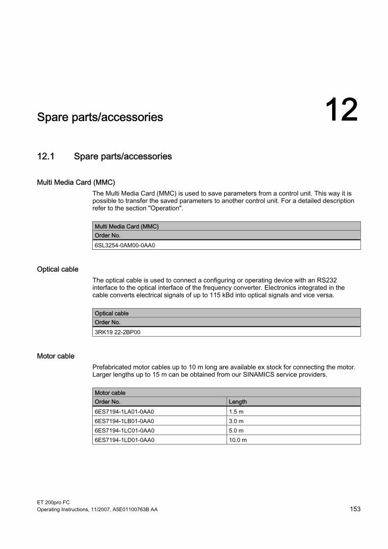
ET 200pro FC Operating Instructions, 11/2007, A5E01100763B AA 153
Spare parts/accessories 1212.1 Spare parts/accessories
Multi Media Card (MMC) The Multi Media Card (MMC) is used to save parameters from a control unit. This way it is possible to transfer the saved parameters to another control unit. For a detailed description refer to the section "Operation".
Multi Media Card (MMC) Order No. 6SL3254-0AM00-0AA0
Optical cable The optical cable is used to connect a configuring or operating device with an RS232 interface to the optical interface of the frequency converter. Electronics integrated in the cable converts electrical signals of up to 115 kBd into optical signals and vice versa.
Optical cable Order No. 3RK19 22-2BP00
Motor cable Prefabricated motor cables up to 10 m long are available ex stock for connecting the motor. Larger lengths up to 15 m can be obtained from our SINAMICS service providers.
Motor cable Order No. Length 6ES7194-1LA01-0AA0 1.5 m 6ES7194-1LB01-0AA0 3.0 m 6ES7194-1LC01-0AA0 5.0 m 6ES7194-1LD01-0AA0 10.0 m

Spare parts/accessories 12.1 Spare parts/accessories
ET 200pro FC 154 Operating Instructions, 11/2007, A5E01100763B AA
Power jumper connector Using the power jumper connector it is possible for one frequency converter to loop through up to 25 A from 3AC 400 V to another frequency converter mounted directly alongside. The common fusing of the primary supply is provided externally.
Power jumper connector Order No. 3RK19 22-2BQ00
Sealing cap for power bus Unused connections without a sealing cap have a degree of protection of only IP54, with a sealing cap it is IP65.
Sealing caps for power bus Order No. Quantity 3RK19 02-0CK00 1 3RK19 02-0CJ00 10

ET 200pro FC Operating Instructions, 11/2007, A5E01100763B AA 155
Appendix AA.1 Acceptance Log
A.1.1 Documentation of acceptance test
Overview Acceptance test No. Date Person carrying-out
Table A-1 Machine description and overview/block diagram
Designation Type Serial No. Manufacturer End customer Block/overview diagram of the machine

Appendix A.1 Acceptance Log
ET 200pro FC 156 Operating Instructions, 11/2007, A5E01100763B AA
Table A-2 Fail-safe functions for each drive
Drive No. FW version SI version Fail-safe function r0018 = r9770 = r0018 = r9770 = r0018 = r9770 = r0018 = r9770 = r0018 = r9770 = r0018 = r9770 = r0018 = r9770 = r0018 = r9770 = r0018 = r9770 = r0018 = r9770 = r0018 = r9770 = r0018 = r9770 = r0018 = r9770 = r0018 = r9770 = r0018 = r9770 = r0018 = r9770 = r0018 = r9770 = r0018 = r9770 = r0018 = r9770 = r0018 = r9770 = r0018 = r9770 = r0018 = r9770 = r0018 = r9770 = r0018 = r9770 = r0018 = r9770 = r0018 = r9770 = r0018 = r9770 = r0018 = r9770 = r0018 = r9770 = r0018 = r9770 = r0018 = r9770 = r0018 = r9770 = r0018 = r9770 =

Appendix A.1 Acceptance Log
ET 200pro FC Operating Instructions, 11/2007, A5E01100763B AA 157
Table A-3 Description of the fail-safe equipment/devices
Drive No. Example: Wiring of the STO terminals (protective door, EMERGENCY STOP), grouping of the STO terminals, etc.
A.1.2 Function test of the acceptance test
Description The function test must be carried-out separately for each individual drive (assuming that the machine permits this to be done).
Executing the test
First commissioning Series commissioning
Please mark

Appendix A.1 Acceptance Log
ET 200pro FC 158 Operating Instructions, 11/2007, A5E01100763B AA
Function test "Safe Torque Off" (STO) This test comprises the following steps:
Table A-4 "Safe Torque Off" function (STO)
No. Description Status 1. Initial state
• Drive is "Ready to Run" (P0010 = 0) • No safety faults and alarms • r9772.0 = r9772.1 = 0 (STO de-selected and inactive) • P9659 = time intervals for the forced checking procedure correctly set
2. Operate the drive 3. Check that the expected drive operates 4. Select STO while issuing the command to operate 5. Check the following:
• The drive coasts-down • The drive is braked by the mechanical brake and held if a brake is being
used • No safety faults • r9772.0 = r9772.1 = 1 (STO selected and active), r9772.14 = 1 if Safe
Brake Control is enabled
6. De-select STO 7. Check the following:
• No safety faults • r9772.0 = r9772.1 = 0 (STO de-selected and inactive) , r9772.14 = 0
8. Check that the expected drive operates if so the following is tested: • That the wiring between the control unit and power module is correct • Correct assignment, drive No. – inverter power module – motor • That the hardware is correctly functioning • That the shutdown paths have been correctly wired • Correct assignment of the STO terminals on the control unit • Correct parameterization of the STO function • Routine for the forced checking procedure of the shutdown paths
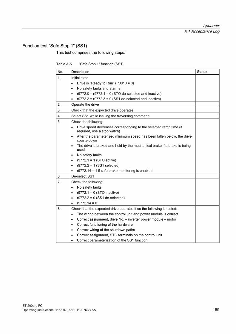
Appendix A.1 Acceptance Log
ET 200pro FC Operating Instructions, 11/2007, A5E01100763B AA 159
Function test "Safe Stop 1" (SS1) This test comprises the following steps:
Table A-5 "Safe Stop 1" function (SS1)
No. Description Status 1. Initial state
• Drive is "Ready to Run" (P0010 = 0) • No safety faults and alarms • r9772.0 = r9772.1 = 0 (STO de-selected and inactive) • r9772.2 = r9772.3 = 0 (SS1 de-selected and inactive)
2. Operate the drive 3. Check that the expected drive operates 4. Select SS1 while issuing the traversing command 5. Check the following:
• Drive speed decreases corresponding to the selected ramp time (if required, use a stop watch)
• After the parameterized minimum speed has been fallen below, the drive coasts-down
• The drive is braked and held by the mechanical brake if a brake is being used
• No safety faults • r9772.1 = 1 (STO active) • r9772.2 = 1 (SS1 selected) • r9772.14 = 1 if safe brake monitoring is enabled
6. De-select SS1 7. Check the following:
• No safety faults • r9772.1 = 0 (STO inactive) • r9772.2 = 0 (SS1 de-selected) • r9772.14 = 0
8. Check that the expected drive operates if so the following is tested: • The wiring between the control unit and power module is correct • Correct assignment, drive No. – inverter power module – motor • Correct functioning of the hardware • Correct wiring of the shutdown paths • Correct assignment, STO terminals on the control unit • Correct parameterization of the SS1 function

Appendix A.1 Acceptance Log
ET 200pro FC 160 Operating Instructions, 11/2007, A5E01100763B AA
Function test "Safely-Limited Speed" (SLS) This test comprises the following steps:
Table A-6 "Safely-Limited Speed" function (SLS)
No. Description Status 1. Initial state
• Drive is "Ready to Run" (P0010 = 0) • No safety faults and alarms • r9772.4 = r9772.5 = 0 (SLS de-selected and inactive)
2. Operate the drive (if the machine permits it, at a higher speed than the parameterized safely-limited speed)
3. Check that the expected drive operates 4. Select SLS while issuing the traversing command 5. Check the following:
• r9772.4 = 1 (SLS selected) • Drive speed decreases corresponding to the selected ramp time or SLS
mode (if required, use an oscilloscope) • After the parameterized safely-limited speed has been fallen below, the
speed remains below this limit – In SLS mode 1 à correct, must be no fault – In SLS mode 0 à LSTO (safety fault at ramping end) – In SLS mode 2 à LSTO (immediately)
• r9772.5 = 1 (SLS active)
6. De-select SLS 7. Check the following:
• No safety faults • r9772.4 = r9772.5 = 0 (SLS de-selected and inactive)
8. Check that the expected drive operates if so the following is tested: • The wiring between the control unit and power module is correct • Correct assignment, drive No. – inverter power module – motor • Correct functioning of the hardware • Correct wiring of the shutdown paths • Correct parameterization of the SLS function

Appendix A.1 Acceptance Log
ET 200pro FC Operating Instructions, 11/2007, A5E01100763B AA 161
A.1.3 Completing the acceptance log
Parameters of the fail-safe functions
Specified value checked? Yes No
Control unit
Checksums
Drive Checksums Name Drive No. Control unit (r9798) Control unit (r9898)
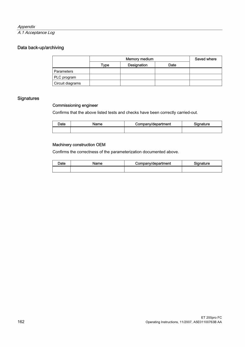
Appendix A.1 Acceptance Log
ET 200pro FC 162 Operating Instructions, 11/2007, A5E01100763B AA
Data back-up/archiving
Memory medium Type Designation Date
Saved where
Parameters PLC program Circuit diagrams
Signatures Commissioning engineer Confirms that the above listed tests and checks have been correctly carried-out.
Date Name Company/department Signature
Machinery construction OEM Confirms the correctness of the parameterization documented above.
Date Name Company/department Signature

Appendix A.2 ESD directives
ET 200pro FC Operating Instructions, 11/2007, A5E01100763B AA 163
A.2 ESD directives
A.2.1 Electromagnetic compatibility
Electromagnetic compatibility (EMC) All manufacturers/assemblers of electrical units which "perform an essentially complete function and are marketed as a single unit designed for the end-user", must comply with the EMC Directive 89/336/EEC. There are three ways for the manufacturer/assembler to verify compliance:
Self-certification The manufacturer declares that the European standards applicable to the electrical environment for which the unit is intended are satisfied. Only standards which have been officially published in the official journal of the European Union are allowed to be cited in the manufacturer's declaration.
Description of technical design A description of the unit's technical design covering its EMC properties may be drawn up. Such a description must be approved by a "competent body" appointed by the responsible European authority. This method enables the use of standards which are still being prepared.
EMC standards The drives were tested according to the EMC product standard EN 61800-3:2004.

Appendix A.2 ESD directives
ET 200pro FC 164 Operating Instructions, 11/2007, A5E01100763B AA
A.2.2 Definition of EMC environment and EMC classes
Classification of EMC behavior The EMC environment and the EMC classes are defined in the EMC product standard EN 61800-3 as follows:
Environment 1 An environment in which there are residential estates and facilities which are connected directly to a public low-voltage supply network without the use of an intermediate transformer.
Note Example: Houses, apartments, commercial units or office rooms within a residential building.
Environment 2 An environment in which there are commercial estates and facilities which are not connected directly to a public low-voltage supply network.
Note Example: Developed commercial sites and other sites which are supplied by a transformer provided specially for the purpose.
Class C1 Power drive system (PDS) with a rated voltage of less than 1000 V for use in residential buildings.
Class C2 Power drive system (PDS) with a rated voltage of less than 1000 V, which is neither fitted with a plug connector nor intended for (easy) transport and which, when used in residential buildings, is designed solely for installation and commissioning by a specialist.
Note A specialist is a person or organization with the necessary skills to install and/or commission a power drive system (PDS) including its EMC aspects.
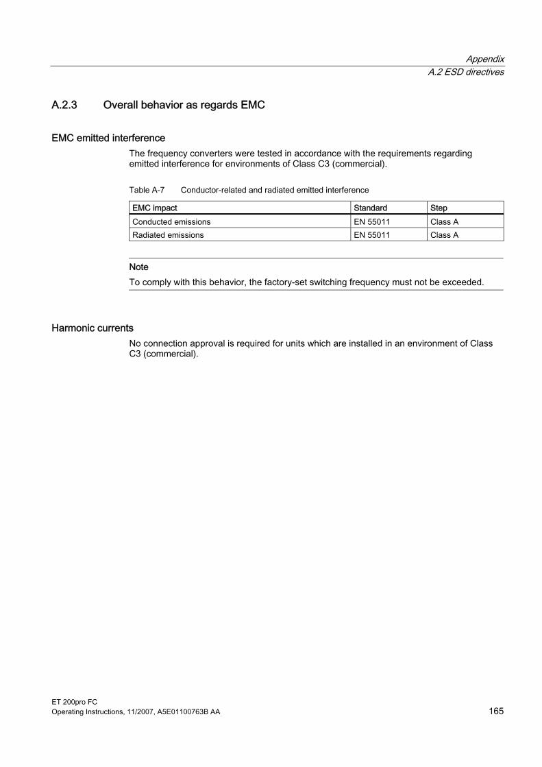
Appendix A.2 ESD directives
ET 200pro FC Operating Instructions, 11/2007, A5E01100763B AA 165
A.2.3 Overall behavior as regards EMC
EMC emitted interference The frequency converters were tested in accordance with the requirements regarding emitted interference for environments of Class C3 (commercial).
Table A-7 Conductor-related and radiated emitted interference
EMC impact Standard Step Conducted emissions EN 55011 Class A Radiated emissions EN 55011 Class A
Note To comply with this behavior, the factory-set switching frequency must not be exceeded.
Harmonic currents No connection approval is required for units which are installed in an environment of Class C3 (commercial).

Appendix A.2 ESD directives
ET 200pro FC 166 Operating Instructions, 11/2007, A5E01100763B AA
EMC immunity The frequency converters were tested in accordance with the interference immunity requirements for environments of Class C3 (commercial).
Table A-8 EMC immunity
EMC impact Standard Step Power criterion
4 kV discharge by contact Electrostatic discharge (ESD)
EN 61000-4-2 8 kV discharge in air
A
Electromagnetic high frequency field
0.15 MHz … 80 MHz 10 V/m
Amplitude modulated
EN 61000-4-3
80 % AM at 1 kHz
A
Transient overvoltages EN 61000-4-4 2 kV at 5 kHz A Voltage surge 1 kV inverse mode (L-L) 1.2/50 μs
EN 61000-4-5 2 kV common mode (L-E)
A
Wired 0.15 MHz … 80 MHz 10 V/rms High frequency common mode
EN 61000-4-6 80 % AM at 1 kHz
A
100 % voltage dip for 3 ms C 30 % voltage dip for 10 ms B 60 % voltage dip for 100 ms C
System interruptions and voltage dips
EN 61000-2-1
95 % voltage dip for 5000 ms C Voltage distortion EN 61000-2-4
Class 3 10 % THD A
Voltage asymmetry EN 61000-2-4 Class 3
3 % inverse reactance A
Frequency fluctuation EN 61000-2-4 Class 3
Rated value 50 Hz or 60 Hz (± 4 %) A
Depth = 40 % Commutation notches EN 60146-1-1 Class B Area = 250 % x degrees
A

Appendix A.2 ESD directives
ET 200pro FC Operating Instructions, 11/2007, A5E01100763B AA 167
A.2.4 ET 200S FC frequency converter in the industrial environment ET 200pro FC frequency converters with integrated Class A EMC filters are designed for use in an industrial environment, provided that the permissible cable lengths are used.
Table A-9 Use in the industrial environment
Requirement for Fields of application Emitted noise Interference immunity
Industry EN 61000-6-4, with Class A filter EN 61000-6-2
Installation guideline for ET 200pro FC frequency converter with integrated EMC filter ● Operation is only permitted for TN line supply systems. ● The converter must be assembled on a grounded plate with a large surface. ● The module rack is to be grounded. ● The maximum length per frequency converter of the shielded power cable is 15 m.
A.2.4.1 ET 200pro FC frequency converter in a drive system in accordance with EN 61800-3
Explanatory notes for EN 61800-3+A11 The EN 61800-3+A11 product standard for "Adjustable speed electrical power drive systems, Part 3: EMC requirements and specific test methods" specifies limit values for noise radiation and interference immunity. The EMC product standard EN 61800-3+A11 does not apply directly to a frequency converter but to a complete drive system, which comprises the complete circuitry, motor and cables in addition to the converter.
Limit values for compliance with EN 61800-3 Category C3 The following table lists the key limit values for compliance with EN 61800-3 on devices with restricted availability for a drive system in accordance with Category C3 (Category C3: Drive system (PDS) with a rated voltage of < 1000 V. For use in a second environment), i.e., use in second environment (industrial) with commissioning and installation carried out by an EMC expert.
Table A-10 Limit values for noise radiation for a drive system compliant with Category C3
EMC phenomena Basic standard for test procedures
Limit value
Radiated emissions EN 55011 Class A, Group 1 Conducted emissions EN 55011 Class A, Group 2

Appendix A.2 ESD directives
ET 200pro FC 168 Operating Instructions, 11/2007, A5E01100763B AA
Table A-11 Limit values for interference immunity for a drive system compliant with Category C3
EMC phenomena Basic standard for test procedures
Level Evaluation criterion
30 %, 10 ms 1) B 60 %, 100 ms 1) C
Voltage dips EN 61800-3-A11
95 %, 5 s 2) C 100 %, 230 ms 2) C Voltage interruptions EN 61800-3-A11 100 %, 120 ms (regenerative feedback) 3)
C
Harmonics at rated load 5. 7. 11. 13. Motor operation EN 61800-3-A11 18,4% 15,6% 8,8% 8,4% Regenerative
feedback EN 61800-3-A11 20,3% 18,4% 9,8% 9,3%
--
Electrostatic discharge EN 61000-4-2 8 kV, air discharge (housing) B Burst EN 61000-4-4 2 kV/5 kHz (electric power cable) B
2 kV, phase – ground (electric power cable)
B Interference pulses
Voltage surge EN 61000-4-5
1 kV, phase – phase (electric power cable)
B
High-frequency electromagnetic field, amplitude-modulated
EN 61000-4-3 80 MHz – 1000 MHz, 10 V/m, 80 % AM
A
Ground leakage current EN 61800-5-1 See the two tables below. -- 1) Reduction of motor speed 2) Shutdown on fault F00003 "Undervoltage" 3) Shutdown on fault F00002 "Overvoltage"
The requirements of the product standard for a drive system, according to C3, are fulfilled. Operation with unshielded cable is not permitted.
Table A-12 Ground leakage currents to EN 61800-5-1 with 15 m CY shielded cable
Motor frequency Ground leakage currents (mA) at pulse frequency Hz 4 kHz 8 kHz 12 kHz 50 1,95 1,39 1,19 20 2,58 1,73 1,37 10 2,70 1,78 1,40 5 2,74 1,79 1,40 Standby 0,53
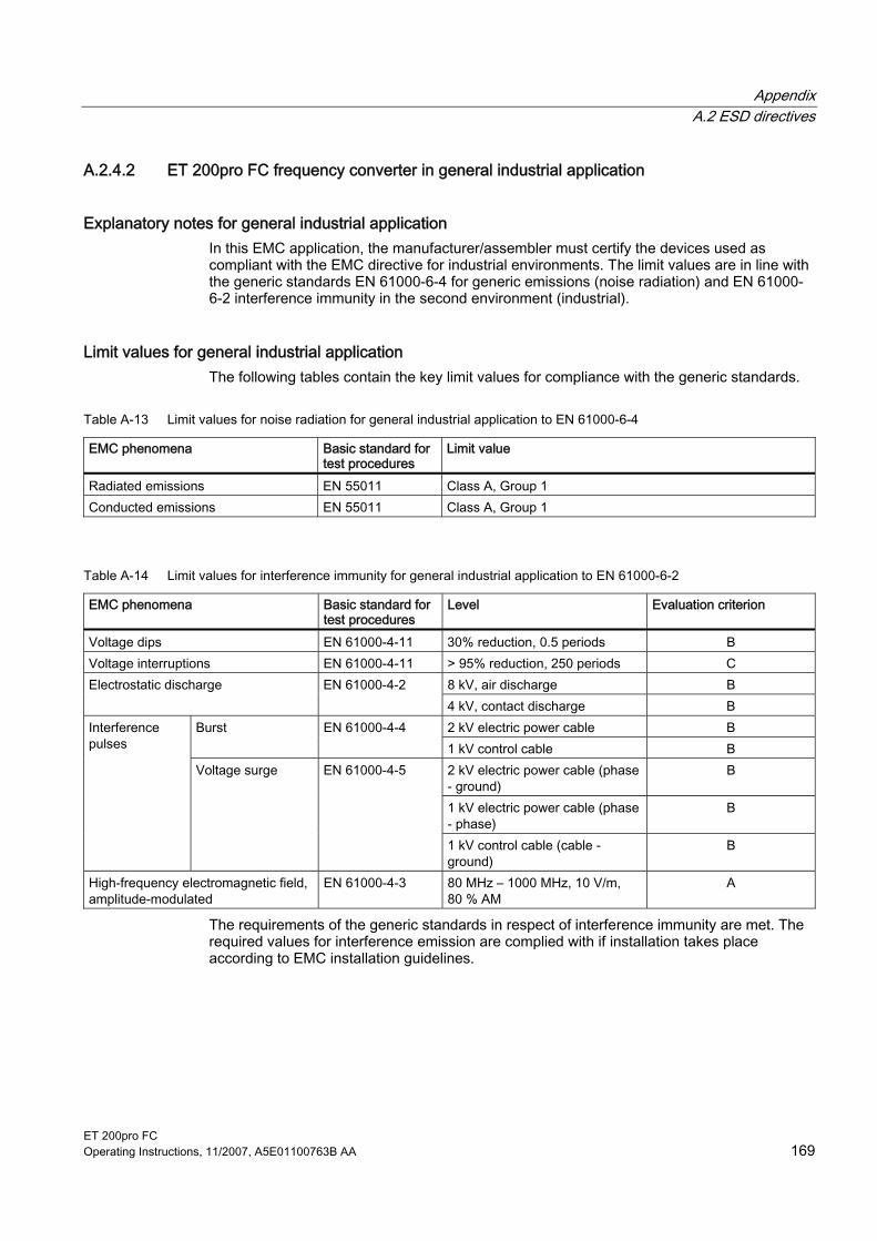
Appendix A.2 ESD directives
ET 200pro FC Operating Instructions, 11/2007, A5E01100763B AA 169
A.2.4.2 ET 200pro FC frequency converter in general industrial application
Explanatory notes for general industrial application In this EMC application, the manufacturer/assembler must certify the devices used as compliant with the EMC directive for industrial environments. The limit values are in line with the generic standards EN 61000-6-4 for generic emissions (noise radiation) and EN 61000-6-2 interference immunity in the second environment (industrial).
Limit values for general industrial application The following tables contain the key limit values for compliance with the generic standards.
Table A-13 Limit values for noise radiation for general industrial application to EN 61000-6-4
EMC phenomena Basic standard for test procedures
Limit value
Radiated emissions EN 55011 Class A, Group 1 Conducted emissions EN 55011 Class A, Group 1
Table A-14 Limit values for interference immunity for general industrial application to EN 61000-6-2
EMC phenomena Basic standard for test procedures
Level Evaluation criterion
Voltage dips EN 61000-4-11 30% reduction, 0.5 periods B Voltage interruptions EN 61000-4-11 > 95% reduction, 250 periods C
8 kV, air discharge B Electrostatic discharge EN 61000-4-2 4 kV, contact discharge B 2 kV electric power cable B Burst EN 61000-4-4 1 kV control cable B 2 kV electric power cable (phase - ground)
B
1 kV electric power cable (phase - phase)
B
Interference pulses
Voltage surge EN 61000-4-5
1 kV control cable (cable - ground)
B
High-frequency electromagnetic field, amplitude-modulated
EN 61000-4-3 80 MHz – 1000 MHz, 10 V/m, 80 % AM
A
The requirements of the generic standards in respect of interference immunity are met. The required values for interference emission are complied with if installation takes place according to EMC installation guidelines.

Appendix A.3 Standards
ET 200pro FC 170 Operating Instructions, 11/2007, A5E01100763B AA
A.3 Standards
Standards and directives
European Low-Voltage Directive The SINAMICS product series meets the requirements of the Low Voltage Directive 73/23/EEC, including the amendment by Directive 98/68/EEC. The devices are certified as complying with the following standards: EN 61800-5-1 - Semiconductor - General Requirements and Line Commutated Converters EN 60204-1 - Safety of Machinery - Electrical Equipment of Machinery
European Machinery Directive The converter series does not fall within the area covered by the machinery directive. However, the use of the products in a typical machine application has been fully assessed for compliance with the main regulations in this directive concerning health and safety. A declaration regarding the general acceptance is available upon request.
European EMC Directive When installed in accordance with the recommendations specified in this manual, the frequency converter complies with all regulations of the EMC directive according to the definition provided by EN 61800-3 "EMC Product Standard for Power Drive Systems". Underwriters Laboratories The device is listed by UL and CUL for power conversion in an environment the pollution degree 2. Comment: UL certification is being processed. National Fire Protection Association (NFPA) compatibility Due to their design features, it is possible that these devices cannot be installed in accordance with the National Electrical Code (NFPA70). These devices are only certified for installation in industrial machines in accordance with the "Electrical Standard for Industrial Machinery" (NFPA79).
ISO 9001 Siemens AG uses a quality management system that meets the requirements of ISO 9001.
EC Machinery Directive 98/37/EG This directive defines basic protection goals for safety technology
EN 292-1 Basic terminology and general principles for design
EN 954-1 Safety-related parts of control systems
EN 1050 Risk assessment
DKE 226.03 Safety-related functions of electrical drive systems in machinery
EN 61800-3 EMC product standard including special test procedures
EN 61800-5-1 Requirements for the safety of electrical power drive systems with adjustable speed
IEC 61508 Functional safety of electrical and electronic systems

ET 200pro FC Operating Instructions, 11/2007, A5E01100763B AA 171
List of abbreviations/acronyms BB.1 Abbreviations
Abbreviations
Abbreviations German English A A... Warnung alarm AC Wechselstrom alternating current AD Analog-Digital-Konverter analog digital converter ADC Analog-Digital-Konverter analog digital converter ADR Adresse address AFM Frequenzmodifikation frequency modification AFM Zusätzliche Frequenzmodulation additional frequency modulation AG Automatisierungsgerät programmable controller AI Analog-Eingang analog input AIN Analog-Eingang analog input AK Anforderungsidentifizierung request identification ALM Active Line Module active line module AO Analog output analog output AOP Advanced Operator Panel advanced operator panel AOUT Analog-Ausgang analog output APC Advanced Positioning Control advanced positioning control ASC Ankerkurzschluss armature short-circuit ASCII Amerikanische Code-Norm für den
Informationsaustausch American standard code for information interchange
ASIC Anwendungsspezifischer integrierter Schaltkreis
application specific integrated circuit
ASM Asynchronmotor induction motor ASP Analog-Sollwert analog setpoint ASVM Asymmetrische Raumvektormodulation asymmetrical space vector modulation B BB Betriebsbedingung operating condition BCC Block-Prüfzeichen unit mark of conformity BCD Binär codierter Dezimalcode binary conversion code

List of abbreviations/acronyms B.1 Abbreviations
ET 200pro FC 172 Operating Instructions, 11/2007, A5E01100763B AA
Abbreviations German English BERO Firmenname für einen
Näherungsschalter trade name for a type of proximity switch
BI Binektor-Eingang binector input BIA Berufsgenossenschaftliches Institut für
Arbeitssicherheit German institute for occupational safety
BICO Binektor-Konnektor-Technologie binector connector technology BIST Testprogramm debugger BLM Basic Line Module basic line module BO Binektor-Ausgang binector output BOP Basic Operator Panel basic operator panel C C Kapazität capacitance C... Safety-Meldung safety message CAN Serielles Bussystem controller area network CB Kommunikationsbaugruppe communication board CBC Kommunikationsbaugruppe CAN communication board CAN CCW gegen den Uhrzeigersinn counter-clockwise CD Compact Disc compact disc CDS Befehlsdatensatz command data set CI Konnektor-Eingang connector input CM Konfigurierungs-Management configuration management CMD Befehl command CNC Computerunterstützte numerische
Steuerung computer numerical control
CO Konnektor-Ausgang connector output CO/BO Konnektor-Ausgang/Binektor-Ausgang connector output/binector output COB-ID CAN Object-Identification can object-identification COM Mittelkontakt eines Wechslerkontaktes common contact of a change-over relay CP Kommunikationsprozessor communications processor CPU Zentralbaugruppe central processing unit CRC Checksummenprüfung cyclic redundancy check CSM Control Supply Module control supply module CT Konstantes Drehmoment; hohe Überlast constant torque CU Control Unit Control Unit CW im Uhrzeigersinn clockwise D DA Digital-Analog-Konverter digital analog converter DAC Digital-Analog-Konverter digital analog converter DC Gleichstrom direct current DCN Gleichstrom negativ direct current negative DCP Gleichstrom positiv direct current positive DDS Antriebsdatensatz drive data set DI, DIN Digital-Eingang digital input

List of abbreviations/acronyms B.1 Abbreviations
ET 200pro FC Operating Instructions, 11/2007, A5E01100763B AA 173
Abbreviations German English DI/DO Digitaleingang/-ausgang bidirektional bidirectional digital input/output DIP DIP-Schalter dip switch DMC DRIVE-CLiQ Module Cabinet (Hub) drive-cliq module cabinet (hub) DO Digital-Ausgang digital output DOUT Digital-Ausgang digital output DP Dezentrale Peripherie (verteilte E/As) decentralized peripherals DPRAM Speicher mit beidseitigem Zugriff dual ported random access memory DRAM Dynamischer Speicher dynamic random access memory DRIVE-CLiQ Drive Component Link with IQ drive component link with iq DS Antriebs-Zustand drive state DSC Dynamic Servo Control dynamic servo control E ECD Ersatzschaltbild equivalent circuit diagram EDS Geberdatensatz encoder data set EEC Europäische Wirtschaftsgemeinschaft European economy community EEPROM Elektrisch löschbarer, programmierbarer
Festwertspeicher erasable programmable read-only memory
EGB Elektrostatisch gefährdete Baugruppen electrostatic sensitive devices (esd) ELCB Erdschluss-Schutzschalter; Fehlerstrom-
Schutzschalter (FI) earth leakage circuit-breaker
ELP Erdschlussüberwachung earth leakage protection EMC Elektromagnetische Verträglichkeit
(EMV) electromagnetic compatibility
EMI Elektomagnetische Störung electromagnetic interference EMF Elektromagnetische Kraft electromagnetic force (EMF) EMK Elektromagnetische Kraft electromagnetic force (EMF) EMV Elektromagnetische Verträglichkeit electromagnetic compatibility (EMC) EN Europäische Norm European standard EnDat Geber-Schnittstelle encoder-data-interface EP Impulsfreigabe enable pulses EPOS Einfachpositionierer basic positioner ES Technisches System engineering system ESB Ersatzschaltbild equivalent circuit diagram ESR Erweitertes Stillsetzen und Rückziehen extended stop and retract F F... Störung fault FAQ Häufig gestellte Fragen frequently asked questions FCC Flussstromregelung flux current control FCC Steuerfunktionsablauf function control chart FCL Schnelle Strombegrenzung fast current limiting FEM Fremderregter Synchronmotor separately excited synchronous motor FEPROM Schreib- und Lesespeicher nichtflüchtig flash eprom FF Festfrequenz fixed frequency

List of abbreviations/acronyms B.1 Abbreviations
ET 200pro FC 174 Operating Instructions, 11/2007, A5E01100763B AA
Abbreviations German English FFB Freier Funktionsbaustein free function block FG Funktionsgenerator function generator FI Fehlerstrom-Schutzschalter earth leakage circuit-breaker (elcb) FOC Feldorientierte Regelung field-oriented control FP Funktionsplan function diagram FREQ Frequenz frequency FSA Baugröße A frame size A FSB Baugröße B frame size B FSC Baugröße C frame size C FSD Baugröße D frame size D FSE Baugröße E frame size E FSF Baugröße F frame size F FW Firmware firmware G GB Gigabyte gigabyte GC Global-Control-Telegramm (Broadcast-
Telegramm) global control telegram (broadcast telegram)
GSD Gerätestammdatei: beschreibt die Merkmale eines PROFIBUS-Slaves
device master file: describes the features of a profibus slave
GSG Inbetriebnahme-Anleitung getting started guide GSV Gate Supply Voltage gate supply voltage GUI ID Eindeutige globale Kennung graphical user interface H HF Hochfrequenz high frequency HFD Hochfrequenzdrossel high frequency reactor HIW Haupt-Istwert main actual value HLG Hochlaufgeber ramp-function generator HMI Mensch-Maschine-Schnittstelle human machine interface HO Konstantes Drehmoment; hohe Überlast constant torque HSW Haupt-Sollwert main setpoint HTL Logik mit hoher Störschwelle,
Hochspannungs-Transistor-Logik high-threshold logic
HW Hardware hardware I i. V. In Vorbereitung: diese Eigenschaft steht
zur Zeit nicht zur Verfügung in preparation: this feature is currently not available
I/O Eingang/Ausgang input/output IBN Inbetriebnahme commissioning ID Identifizierung identifier IEC Internationale Norm in der Elektrotechnik international electrotechnical
commission IGBT Bipolartransistor mit isolierter
Steuerelektrode insulated gate bipolar transistor
IL Impulslöschung pulse suppression

List of abbreviations/acronyms B.1 Abbreviations
ET 200pro FC Operating Instructions, 11/2007, A5E01100763B AA 175
Abbreviations German English IND Unter-Index sub index IP65 Schutzgrad 65 grade of protection 65 IT Drehstromversorgungsnetz ungeerdet Insulated three-phase supply network IVP Interner Spannungsschutz internal voltage protection J JOG Tippen, JOG-Betrieb jogging K KDV Kreuzweiser Datenvergleich data cross-checking KIB Kinetische Pufferung KIP Kinetische Pufferung kinetic buffering Kp Proportionalverstärkung proportional gain KTY Spezieller Temperatursensor special temperature sensor L L Induktivität inductance LCD Flüssigkristallanzeige liquid-crystal display LED Leuchtdiode light emitting diode LGE Länge length LIN Linearmotor linear motor LO Leichte Überlast (Veränderbares
Drehmoment) light overload
LR Lageregler position controller LSB Niederstwertiges Bit least significant bit LSS Netzschalter line side switch LU Längeneinheit length unit LWL Lichtwellenleiter optical fibre M M Masse reference potential, zero potential MB Megabyte megabyte MCC Motion Control Chart motion control chart MDS Motordatensatz motor data set MHB Motor-Haltebremse motor holding brake MLFB Maschinenlesbare
Fabrikatebezeichnung machine-readable product designation
MLP Mehrsprachen-Paket multi language package MMC Mensch-Maschine-Kommunikation man-machine communication MMC Micro Memory Card
kompakte Speicherkarte für SIMATIC Micro Memory Card Compact memory card for SIMATIC
MOP Motorpotentiometer motor potentiometer MSB Höchstwertiges Bit most significant bit MSCY_C1 Zyklische Kommunikation zwischen
Master (Klasse 1) und Slave master slave cycle class 1
MT Messtaster measuring probe N

List of abbreviations/acronyms B.1 Abbreviations
ET 200pro FC 176 Operating Instructions, 11/2007, A5E01100763B AA
Abbreviations German English N. C. Nicht angeschlossen not connected N... Keine Meldung oder Interne Meldung no report NAMUR Normenarbeitsgemeinschaft für Mess-
und Regeltechnik in der chemischen Industrie
standardization association for measurement and control in chemical industries
NC Numerische Steuerung numerical control NC Ruhekontakt; Öffner normally closed (contact) NEMA Normengremium in USA (United States
of America) national electrical manufacturers association
NM Nullmarke zero mark NO Arbeitskontakt; Schließer normally open (contact) NPN Negativ positiv negativ negative positive negative O OA Open Architecture open architecture OEM Original Equipment Manufacturer original equipment manufacturer OLM Optische Koppelbaugruppe OLP Stecker für optische Verbindung optical link plug OMI Option Module Interface option module interface OP Bedienfeld operator panel OPI Betriebsanleitung operating instruction P P... Einstellparameter adjustable parameter PcCtrl Steuerungshoheit master control PDS Leistungsteildatensatz, Antriebssystem power unit data set PE Schutzerde protective earth PELV Schutzkleinspannung protective extra low voltage PEM Permanenterregter Synchronmotor permanent-magnet synchronous motor PG Programmiergerät programming terminal PI Proportional Integral proportional integral PID Proportional Integral Differential proportional integral differential PID Proportional-Integral-Differential-Regler proportional integral differential controllerPKE Parameterkennung parameter ID PKW Parameterkennung Wert parameter ID value PLC Speicherprogrammierbare Steuerung
(SPS) programmable logical controller (PLC)
PLI Listenhandbuch parameter list PLL Baustein zur Synchronisierung phase locked loop PM Netzteil power module PM-IF Leistungsteil Schnittstelle power module interface PNO PROFIBUS Nutzerorganisation profibus user organisation PNP Positiv negativ positiv positive negative positive PNU Parameternummer parameter number POT Potentiometer potentiometer

List of abbreviations/acronyms B.1 Abbreviations
ET 200pro FC Operating Instructions, 11/2007, A5E01100763B AA 177
Abbreviations German English PPI Punkt zu Punkt Schnittstelle point to point interface PPO Parameter-Prozessdatenobjekt parameter process data object PRBS Weißes Rauschen pseudo random binary signal PROFIBUS Serieller Datenbus process field bus PROFIdrive Antriebsstandard drive standard PROFINET Serieller Datenbus process field network PS Stromversorgung power supply PSA Power Stack Adapter power stack adapter PTC Positiver Temperaturkoeffizient positive temperature coefficient PTP Punkt zu Punkt point to point PWE Parameterwert parameter value PWM Pulsweitenmodulation pulse width modulation PX Leistungserweiterung power extension PZD PROFIBUS Prozessdaten profibus process data Q QC Schnellinbetriebnahme quick commissioning R r... Beobachtungsparameter (nur lesbar) display parameter (read only) RAM Speicher zum Lesen und Schreiben random access memory RCCB Fehlerstrom-Schutzschalter residual current circuit-breaker RCD Fehlerstrom-Schutzschalter residual current device RFG Hochlaufgeber ramp-function generator RFI Hochfrequenzstörung radio frequency interference RJ45 Norm. Beschreibt eine 8-polige
Steckverbindung mit Twisted-Pair Ethernet.
standard. Describes an 8-pole plug connector with twisted pair ethernet.
RKA Rückkühlanlage recooling system RO Nur lesbar read only ROM Festwertspeicher read-only memory RPDO Receive Process Data Object receive process data object RPM Umdrehungen pro Minute revolutions per minute RS232 Serielle Schnittstelle serial interface RS485 Norm. Beschreibt die Physik einer
digitalen seriellen Schnittstelle. standard. Describes the physical characteristics of a digital serial interface.
RTC Echtzeituhr real time clock RTOS Echtzeitbetriebssystem real time operating system S S1 Dauerbetrieb continuous operation S3 Aussetzbetrieb periodic duty SBC Sichere Bremsenansteuerung safe brake control SBH Sicherer Betriebshalt safe operating stop SBR Sichere Bremsrampe safe braking ramp

List of abbreviations/acronyms B.1 Abbreviations
ET 200pro FC 178 Operating Instructions, 11/2007, A5E01100763B AA
Abbreviations German English SBT Sicherer Bremsentest safe brake test SCL Skalierung scale SDI Sichere Richtung safe direction SDP Statusanzeigeeinheit staus display unit SE Sicherer Software-Endschalter safe software limit switch SFC Systemfunktion System function SG Sicher reduzierte Geschwindigkeit safely reduced speed SGA Sicherheitsgerichteter Ausgang safety-related output SGE Sicherheitsgerichteter Eingang safety-related input SH Sicherer Halt safe standstill SI Safety Integrated safety integrated SIL Sicherheitsintegritätsgrad safety integrity level SLI Sicheres Schrittmaß safely limited increment SLM Smart Line Module smart line module SLP Sichere Endlage safely limited position SLS Sicher begrenzte Geschwindigkeit safely limited speed SLVC Geberlose Vektorregelung sensorless vector control SM Sensor Module sensor module SMC Sensor Module Cabinet sensor module cabinet SME Sensor Module External sensor module external SN Sicherer Software-Nocken safe software cam SOL Serielle Verbindung als Option serial option link SOS Sicherer Betriebshalt safe operational stop SPC Sollwertkanal setpoint channel SPS Speicherprogrammierbare Steuerung programmable logic controller (plc) SS1 Sicherer Stopp 1 safe stop 1 SSI Synchron Serielle Schnittstelle synchronous serial interface SSM Sichere Geschwindigkeitsanzeige n < nx safe speed monitoring n < nx SSR Sichere Bremsrampe safe stop ramp STO Sicher abgeschaltetes Moment safe torque off STW PROFIBUS Steuerwort profibus control byte STW Steuerwort control word STX Textanfang text start SVM Raumvektormodulation space vector modulation T TB Terminal Board terminal board TIA Totally Integrated Automation totally integrated automation TM Terminal Module terminal module TN Drehstromversorgungsnetz geerdet grounded three-phase supply network Tn Nachstellzeit integral time TPDO Transmit Process Data Object transmit process data object TT Drehstromversorgungsnetz geerdet grounded three-phase supply network

List of abbreviations/acronyms B.1 Abbreviations
ET 200pro FC Operating Instructions, 11/2007, A5E01100763B AA 179
Abbreviations German English TTL Transistor-Transistor-Logik transistor-transistor-logic U U/f Spannung/Frequenz voltage/frequency UL Underwriters Laboratories Inc. underwriters laboratories inc. USS Universelle serielle Schnittstelle universal serial interface USV Unterbrechungsfreie Stromversorgung uninterruptible power supply V VC Vektorregelung vector control Vdc Zwischenkreisspannung dc link voltage VdcN Teilzwischenkreisspannung negativ partial dc link voltage negative VdcP Teilzwischenkreisspannung positiv partial dc link voltage positive VDE Verband Deutscher Elektrotechniker association of german electrical
engineers VDI Verein Deutscher Ingenieure association of german engineers Vpp Volt Spitze zu Spitze volt peak to peak VSM Voltage Sensing Module voltage sensing module VT Variables Drehmoment variable torque W WEA Wiedereinschaltautomatik automatic restart WZM Werkzeugmaschine machine tool X XML Erweiterbare Auszeichnungssprache
(Standardsprache für Web-Publishing und Dokumentenmanagement)
extensible markup language
Z ZK Zwischenkreis dc link ZSW PROFIBUS Zustandswort profibus status byte ZSW Zustandswort status byte ZUSW Zusatz-Sollwert supplementary setpoint


ET 200pro FC Operating Instructions, 11/2007, A5E01100763B AA 181
Glossary
Duty cycle Electrical machines run in one of the modes of operation described below. This results in the machine being subjected to different thermal loads during a duty cycle (S1 to S9). ● S1: Continuous operation ● S2: Short-time operation ● S3: Intermittent operation without startup procedure ● S4: Intermittent operation with startup procedure ● S5: Intermittent operation with startup procedure and electrical braking ● S6: Continuous operation with intermittent load ● S7: Uninterrupted operation (with startup and electrical braking) ● S8: Uninterrupted operation with periodic speed variations ● S9: Uninterrupted operation with non-periodic load and speed variations
ET 200pro Distributed I/O System The ET 200pro distributed I/O system is a highly modular and very flexible DP slave with IP65 degree of protection. The interface to the fieldbus is always provided by an IM 151 interface module. Implementations vary from one application to the next.
Expectations The monitoring functions in each monitoring channel work on the principle that a defined status must prevail before each action is carried out and a specific acknowledgement must follow each action. If these expectations of a monitoring channel are not fulfilled, the drive coasts to a standstill (two-channel) and an appropriate message is output.
General installation guidelines Safety-related motor starters and frequency converters can be operated in tandem downstream of a module able to switch safe switch-off signals on the ET200 backplane bus. The F switch supplies two switch-off signals, F0 and F1; the repair switch module F-RSM only supplies F0. The STARTER software can be used to assign switch-off signals at will if a different application ID is selected for the frequency converters.

Glossary
ET 200pro FC 182 Operating Instructions, 11/2007, A5E01100763B AA
Load groups A load group contains a frequency converter with a power supply and all the frequency converters located to the right of it as far as the next frequency converter/motor starter with a power supply. All ET 200pro FCs sharing one incoming power bus supply are referred to as a "load group". A load group can differ from a potential group. An additional incoming power bus supply may be needed within a group of frequency converters supplied by the same power module, in order to avoid exceeding the rated operational current (aggregate current) of the terminal modules. The aggregate current of the power bus must not exceed 50 A.
Monitoring cycle The safety-related monitoring functions for the drives are executed cyclically in ms.
Monitoring parameters Parameters which can only be monitored are identified by the prefix "r". These parameters are used to display internal variables, e.g., statuses or actual values.
Examples of notation: r0002 Monitoring parameter 2 r0052.3 Monitoring parameter 52, bit 03 r0947[2] Monitoring parameter 947 index 2 r0964[0 ... 4] Monitoring parameter 964 with 5 indices (indices 0 to 4)
Parameter attributes In the parameter list, the header for each parameter shows all attributes and groups associated with it.
Index The index is used to define a parameter (e.g., P0013[20]) with a number of following elements (in this case, 20). Each individual index is defined using a numerical value. In relation to a parameter, this means that one indexed parameter can exhibit a number of values. The values are addressed using the parameter number and index value (e.g. P0013[0], P0013[1], P0013[2], P0013[3], P0013[4]). Indexed parameters are used, for example, for: ● Drive data sets (DDS) ● Command data sets (CDS) ● Subfunctions

Glossary
ET 200pro FC Operating Instructions, 11/2007, A5E01100763B AA 183
BICO The following types of interconnectable parameter are available. The function manual contains a description of the BICO technology.
Table 12-15 BICO parameter attributes
BICO Description BI Binector input BO Binector output CI Connector input CO Connector output CO/BO Connector output/Binector output
Changeable in "P" parameters can only be changed dependent upon the status of the frequency converter. The parameter value will not be applied unless the current status is listed in the "changeable" parameter attribute. For example, the parameter for quick commissioning P0010 with the attribute "CT" can only be changed in quick commissioning "C" or standby status "T" and not in motor mode "U".
Table 12-16 Changeable parameter attributes
Status Description C Quick commissioning U Running (drive running) T Drive ready to start
Data types The data type associated with a parameter defines the widest possible range of values. Five data types are used on the frequency converter. They represent either an unsigned integer value (U16, U32) or a floating point value. The range of values is frequently limited by a minimum and a maximum value (min., max.) or using variables associated with the frequency converter/motor.
Table 12-17 Data type of parameter attributes
Data type Description U16 16-bit unsigned integer value U32 32-bit unsigned integer value I16 16-bit signed integer value I32 32-bit signed integer value Float A simple-accuracy floating point value compliant with IEEE standard format
Max. range of values: -3.39e+38 – +3.39e+38
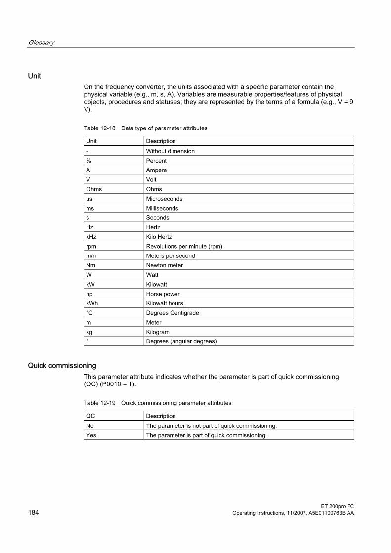
Glossary
ET 200pro FC 184 Operating Instructions, 11/2007, A5E01100763B AA
Unit On the frequency converter, the units associated with a specific parameter contain the physical variable (e.g., m, s, A). Variables are measurable properties/features of physical objects, procedures and statuses; they are represented by the terms of a formula (e.g., V = 9 V).
Table 12-18 Data type of parameter attributes
Unit Description - Without dimension % Percent A Ampere V Volt Ohms Ohms us Microseconds ms Milliseconds s Seconds Hz Hertz kHz Kilo Hertz rpm Revolutions per minute (rpm) m/n Meters per second Nm Newton meter W Watt kW Kilowatt hp Horse power kWh Kilowatt hours °C Degrees Centigrade m Meter kg Kilogram ° Degrees (angular degrees)
Quick commissioning This parameter attribute indicates whether the parameter is part of quick commissioning (QC) (P0010 = 1).
Table 12-19 Quick commissioning parameter attributes
QC Description No The parameter is not part of quick commissioning. Yes The parameter is part of quick commissioning.

Glossary
ET 200pro FC Operating Instructions, 11/2007, A5E01100763B AA 185
Range of values The range of values specified by the data type is limited by the minimum and maximum value (min., max.) and by the variables associated with the frequency converter/motor. Quick commissioning is dependent upon the parameters being set to default values. These values (min., max., def.) are permanently stored in the frequency converter and cannot be changed by the user.
Table 12-20 Range of values of parameter attributes
Range of values Description - No value entered (e.g. "r-parameter") Min Minimum value Max Maximum value Def Default value
Data sets You will find a more detailed description of the data sets in the corresponding section.
Table 12-21 Changeable parameter attributes
BICO Description CDS Command data set DDS Drive data set
Potential groups A potential group contains a power module and all modules located to the right of it as far as an ET 200pro terminating module or the next power module.
Note Frequency converters and motor starters can be operated together in the same potential group.
Switch-off signal paths The fail-safe frequency converter has two separate switch-off signal paths for the power electronics. All switch-off signal paths are low active, thereby ensuring that the system is always switched to a safe state if a component fails or in the event of an open circuit. If a fault is detected on the switch-off signal paths, the frequency converter is passivated. In this case, passivation cannot simply be acknowledged.
Two-channel monitoring structure All the main safety-related hardware and software functions are implemented in two independent monitoring channels (e.g., switch-off signal paths, data management, data comparison).

Glossary
ET 200pro FC 186 Operating Instructions, 11/2007, A5E01100763B AA
Upload and download Upload is understood to mean the saving of parameters from the EEPROM of a frequency converter to a PC (using STARTER) or to an MMC. Download is understood to mean the transferring of a parameter set saved on a PC or an MMC into the RAM or EEPROM memory of a frequency converter.
Writable parameters Parameters that can be written and displayed are identified by the prefix "P". These parameters have a direct impact on the behavior of a function. Their values are written to a non-volatile memory (EEPROM) if the corresponding option has been selected (non-volatile data storage). Otherwise, these values are written to the processor's volatile memory (RAM) and will be lost in the event of a power failure or restart. Examples of the standard notation we always use in our manuals appear below.
Examples of notation: P0970 Parameter 970 P0748.1 Parameter 748, bit 01 P0819[1] Parameter 819 index 1 P0013[0 ... 19] Parameter 13 with 20 indices (indices 0 … 19)

ET 200pro FC Operating Instructions, 11/2007, A5E01100763B AA 187
Index
A A&D Technical support, 8
America (Johnson City), 8 Asia/Pacific (Beijing), 8 Europe/Africa (Erlangen), 8 Online Service and support, 8
Ambient conditions Frequency converter, 149
Application ID, 133
C Characteristics
ET 200pro FC, 21 Classification of EMC behavior, 164 Commissioning
Motor terminal box, 80 Commissioning procedure using STARTER, 85 Communication, 33 Communication interfaces, 33 Configuration options, 24
D Description
ET 200pro FC, 21 Description of technical design, 163 Diagnostics through LEDs, 140 Dimensional drawing of wide module rack, 38
E Electromagnetic compatibility, 163
Drive system in accordance with EN 61800-3, 167 In the industrial environment, 167 Typical applications, 169
EMC emitted interference, 165 EMC standards, 163 ET 200pro FC
Characteristics, 21 Description, 21
Functions, 22 Installation, 21 Special features, 21
ET 200S FC frequency converter Configuration options, 24
ET 200S FC frequency converters Maximum expansion, 29
F Fieldbus interface, 34 Frequency converter
Ambient conditions, 149 Functional ground (FE), 40 Functions
ET 200pro FC, 22
H Hardware components, 57
I IEC motor, 80 Installation
ET 200pro FC, 21 Integrating ET 200pro FC into SIMATIC S7, 57 Interfaces, 33
Fieldbus interface, 34 MMC slot, 35
Interfaces RS232 interface, 34
M Maximum expansion, 37
ET 200S FC frequency converters, 29 Memory
External, 124 Internal, 124
MMC slot, 35 Motor cable, 153 Motor data identification, 87, 90 Multi-Media Card, 153

Index
ET 200pro FC 188 Operating Instructions, 11/2007, A5E01100763B AA
N NEMA motor, 80
O Operational performance, 137 Optical cable, 153
P Parameter change during operation, 138 Parameter change using STARTER, 86 Parameter transfer, 124
Fault codes, 131 Memory media, 124 Remedy for F00395, 131 With MMC, 126 With PC (STARTER), 129 With PLC, 130
Power jumper connector, 154 PTC interface, 35
R Repairs, 19 Replacement of the frequency converter, 136 RS232 interface, 34
S Safety notes
Transport and storage, 19 Sealing cap for power bus, 154 Self-certification, 163 SIMATIC S7 ET 200pro FC ~ integrating in, 57 Software components, 57 Special features
ET 200pro FC, 21 Standard commissioning
With MMC, 135 With STARTER, 135
Standards and directives, 170 STARTER projects, 86 Status display through LEDs, 30, 140 STEP 7, 57
T Transfer of parameters
Download, 125 Supplementary conditions, 125 Upload, 125


Siemens AG
Automation and DrivesStandard DrivesPostfach 32 6991050 ERLANGENDEUTSCHLAND
www.siemens.de/et200pro-fc