operating instructions and parts manual hydraulic pipe...
TRANSCRIPT
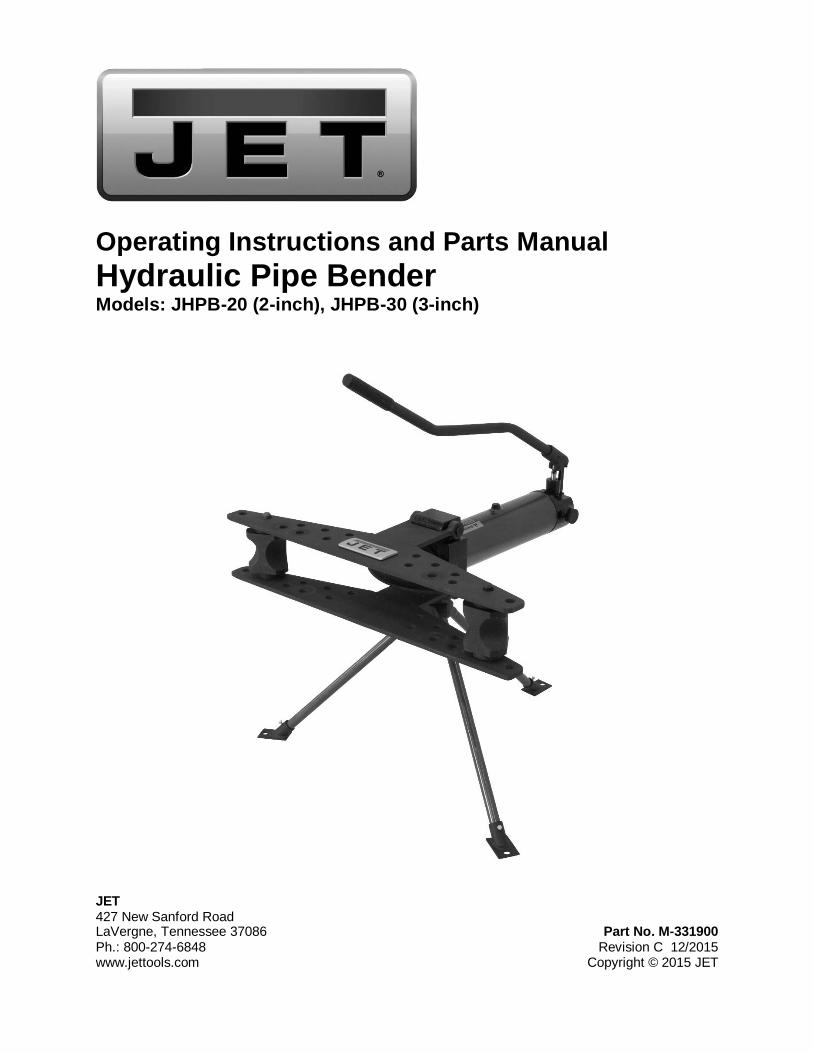
Operating Instructions and Parts Manual Hydraulic Pipe Bender Models: JHPB-20 (2-inch), JHPB-30 (3-inch)
JET 427 New Sanford Road LaVergne, Tennessee 37086 Part No. M-331900 Ph.: 800-274-6848 Revision C 12/2015 www.jettools.com Copyright © 2015 JET
2
Warranty and Service JET warrants every product it sells against manufacturers’ defects. If one of our tools needs service or repair, please contact Technical Service by calling 1-800-274-6846, 8AM to 5PM CST, Monday through Friday.
Warranty Period The general warranty lasts for the time period specified in the literature included with your product or on the official JET branded website.
• JET products carry a limited warranty which varies in duration based upon the product. (See chart below) • Accessories carry a limited warranty of one year from the date of receipt. • Consumable items are defined as expendable parts or accessories expected to become inoperable within a
reasonable amount of use and are covered by a 90 day limited warranty against manufacturer’s defects.
Who is Covered This warranty covers only the initial purchaser of the product from the date of delivery.
What is Covered This warranty covers any defects in workmanship or materials subject to the limitations stated below. This warranty does not cover failures due directly or indirectly to misuse, abuse, negligence or accidents, normal wear-and-tear, improper repair, alterations or lack of maintenance. JET woodworking machinery is designed to be used with Wood. Use of these machines in the processing of metal, plastics, or other materials may void the warranty. The exceptions are acrylics and other natural items that are made specifically for wood turning.
Warranty Limitations Woodworking products with a Five Year Warranty that are used for commercial or industrial purposes default to a Two Year Warranty. Please contact Technical Service at 1-800-274-6846 for further clarification.
How to Get Technical Support Please contact Technical Service by calling 1-800-274-6846. Please note that you will be asked to provide proof of initial purchase when calling. If a product requires further inspection, the Technical Service representative will explain and assist with any additional action needed. JET has Authorized Service Centers located throughout the United States. For the name of an Authorized Service Center in your area call 1-800-274-6846 or use the Service Center Locator on the JET website.
More Information JET is constantly adding new products. For complete, up-to-date product information, check with your local distributor or visit the JET website.
How State Law Applies This warranty gives you specific legal rights, subject to applicable state law.
Limitations on This Warranty JET LIMITS ALL IMPLIED WARRANTIES TO THE PERIOD OF THE LIMITED WARRANTY FOR EACH PRODUCT. EXCEPT AS STATED HEREIN, ANY IMPLIED WARRANTIES OF MERCHANTABILITY AND FITNESS FOR A PARTICULAR PURPOSE ARE EXCLUDED. SOME STATES DO NOT ALLOW LIMITATIONS ON HOW LONG AN IMPLIED WARRANTY LASTS, SO THE ABOVE LIMITATION MAY NOT APPLY TO YOU. JET SHALL IN NO EVENT BE LIABLE FOR DEATH, INJURIES TO PERSONS OR PROPERTY, OR FOR INCIDENTAL, CONTINGENT, SPECIAL, OR CONSEQUENTIAL DAMAGES ARISING FROM THE USE OF OUR PRODUCTS. SOME STATES DO NOT ALLOW THE EXCLUSION OR LIMITATION OF INCIDENTAL OR CONSEQUENTIAL DAMAGES, SO THE ABOVE LIMITATION OR EXCLUSION MAY NOT APPLY TO YOU. JET sells through distributors only. The specifications listed in JET printed materials and on official JET website are given as general information and are not binding. JET reserves the right to effect at any time, without prior notice, those alterations to parts, fittings, and accessory equipment which they may deem necessary for any reason whatsoever. JET® branded products are not sold in Canada by JPW Industries, Inc.
Product Listing with Warranty Period 90 Days – Parts; Consumable items 1 Year – Motors; Machine Accessories 2 Year – Metalworking Machinery; Electric Hoists, Electric Hoist Accessories; Woodworking Machinery used for industrial or commercial purposes 5 Year – Woodworking Machinery Limited Lifetime – JET Parallel clamps; VOLT Series Electric Hoists; Manual Hoists; Manual Hoist Accessories; Shop Tools; Warehouse & Dock products; Hand Tools; Air Tools
NOTE: JET is a division of JPW Industries, Inc. References in this document to JET also apply to JPW Industries, Inc., or any of its successors in interest to the JET brand.
3
Table of contents Section Page Warranty and Service ............................................................................................................................................ 2 Table of contents ................................................................................................................................................... 3 Safety warnings ..................................................................................................................................................... 4 Specifications ........................................................................................................................................................ 5 Unpacking ............................................................................................................................................................. 6
Contents of Shipping Container ........................................................................................................................ 6 Contents of Hardware Bag ................................................................................................................................ 6
Assembly ............................................................................................................................................................... 7 Operation .............................................................................................................................................................. 8
Securing the Pipe Bender ................................................................................................................................. 8 Direction of the Pipe Bender ............................................................................................................................. 8 When Using for the First Time ........................................................................................................................... 8 To Bend a Pipe .................................................................................................................................................. 8
Lubrication ............................................................................................................................................................. 8 Troubleshooting the JHPB Pipe Benders .............................................................................................................. 9 Replacement Parts ................................................................................................................................................ 9
Parts Breakdown – JHPB-20 and JHPB-30 Pipe Benders .............................................................................. 10 Parts List – JHPB-20 and JHPB-30 Pipe Benders .......................................................................................... 11
4
Safety warnings 1. Read and understand the entire owner's manual before attempting assembly or operation.
2. Read and understand the warnings posted on the machine and in this manual. Failure to comply with all of these warnings may cause serious injury.
3. Replace the warning labels if they become obscured or removed.
4. This pipe bender is designed and intended for use by properly trained and experienced personnel only. If you are not familiar with the proper and safe operation of a pipe bender, do not use until proper training and knowledge have been obtained.
5. Do not use this machine for other than its intended use. If used for other purposes, JET disclaims any real or implied warranty and holds itself harmless from any injury that may result from that use.
6. Always wear approved safety glasses/face shields while using this machine. Everyday eyeglasses only have impact resistant lenses; they are not safety glasses.
7. Before operating this pipe bender, remove tie, rings, watches and other jewelry, and roll sleeves up past the elbows. Remove all loose clothing and confine long hair. Non-slip footwear or anti-skid floor strips are recommended. Do not wear gloves.
8. Do not operate this machine while tired or under the influence of drugs, alcohol or any medication.
9. Check damaged parts. Before further use of the machine, a guard or other part that is damaged should be carefully checked to determine that it will operate properly and perform its intended function. Check for alignment of moving parts, binding of moving parts, breakage of parts, mounting and any other conditions that may affect its operation. A guard or other part that is damaged should be properly repaired or replaced.
10. Provide for adequate space surrounding work area and non-glare, overhead lighting.
11. Keep the floor around the machine clean and free of scrap material, oil and grease.
12. Keep visitors a safe distance from the work area. Keep children away.
13. Give your work undivided attention. Looking around, carrying on a conversation and “horse-play” are careless acts that can result in serious injury.
14. Maintain a balanced stance and do not overreach or use excessive force to perform any machine operation.
15. Use the right tool. Do not force a tool or attachment to do a job for which it was not designed. The right tool will do the job better and safer.
16. Use recommended accessories; improper accessories may be hazardous.
17. Maintain tools with care and clean for the best and safest performance. Follow instructions for lubricating and changing accessories.
Familiarize yourself with the following safety notices used in this manual:
This means that if precautions are not heeded, it may result in minor injury and/or possible machine damage.
This means that if precautions are not heeded, it may result in serious, or possibly even fatal, injury.
- - SAVE THESE INSTRUCTIONS - -
5
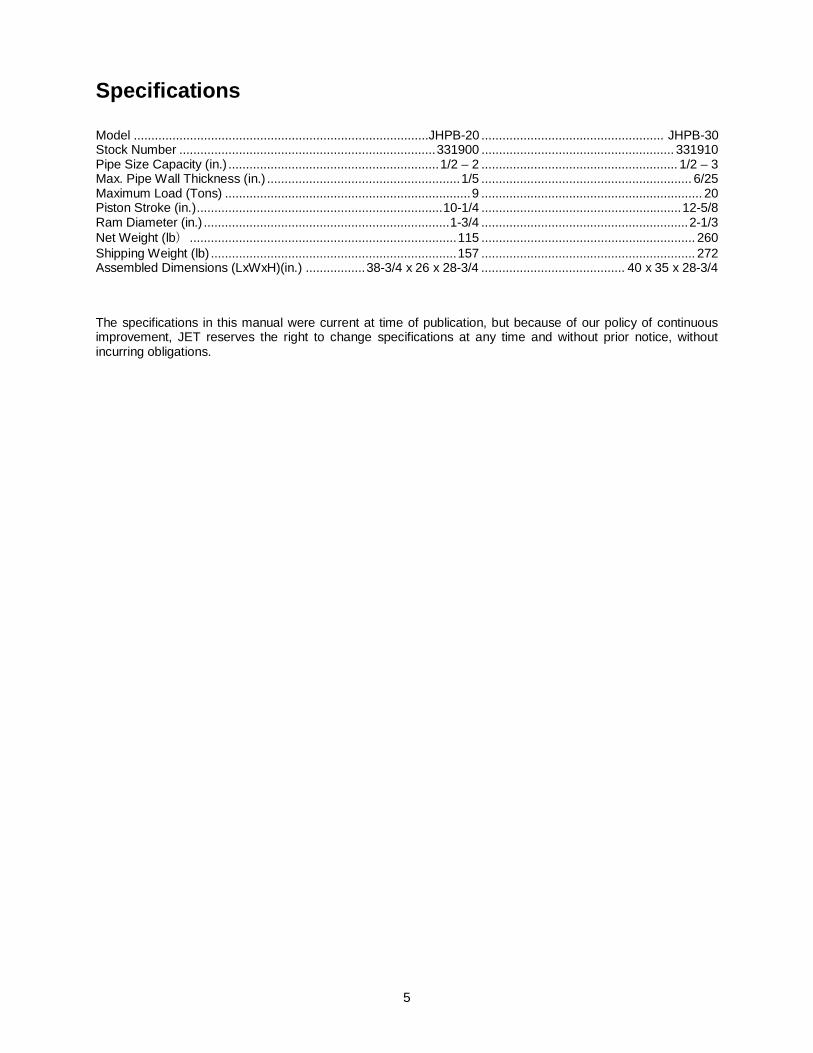
Specifications Model ....................................................................................JHPB-20 .................................................... JHPB-30 Stock Number ......................................................................... 331900 ....................................................... 331910 Pipe Size Capacity (in.) ............................................................ 1/2 – 2 ........................................................ 1/2 – 3 Max. Pipe Wall Thickness (in.) ....................................................... 1/5 ............................................................ 6/25 Maximum Load (Tons) ...................................................................... 9 ............................................................... 20 Piston Stroke (in.) ...................................................................... 10-1/4 ......................................................... 12-5/8 Ram Diameter (in.) ...................................................................... 1-3/4 ........................................................... 2-1/3 Net Weight (lb) ............................................................................ 115 ............................................................. 260 Shipping Weight (lb) ...................................................................... 157 ............................................................. 272 Assembled Dimensions (LxWxH)(in.) ................. 38-3/4 x 26 x 28-3/4 ......................................... 40 x 35 x 28-3/4
The specifications in this manual were current at time of publication, but because of our policy of continuous improvement, JET reserves the right to change specifications at any time and without prior notice, without incurring obligations.
6
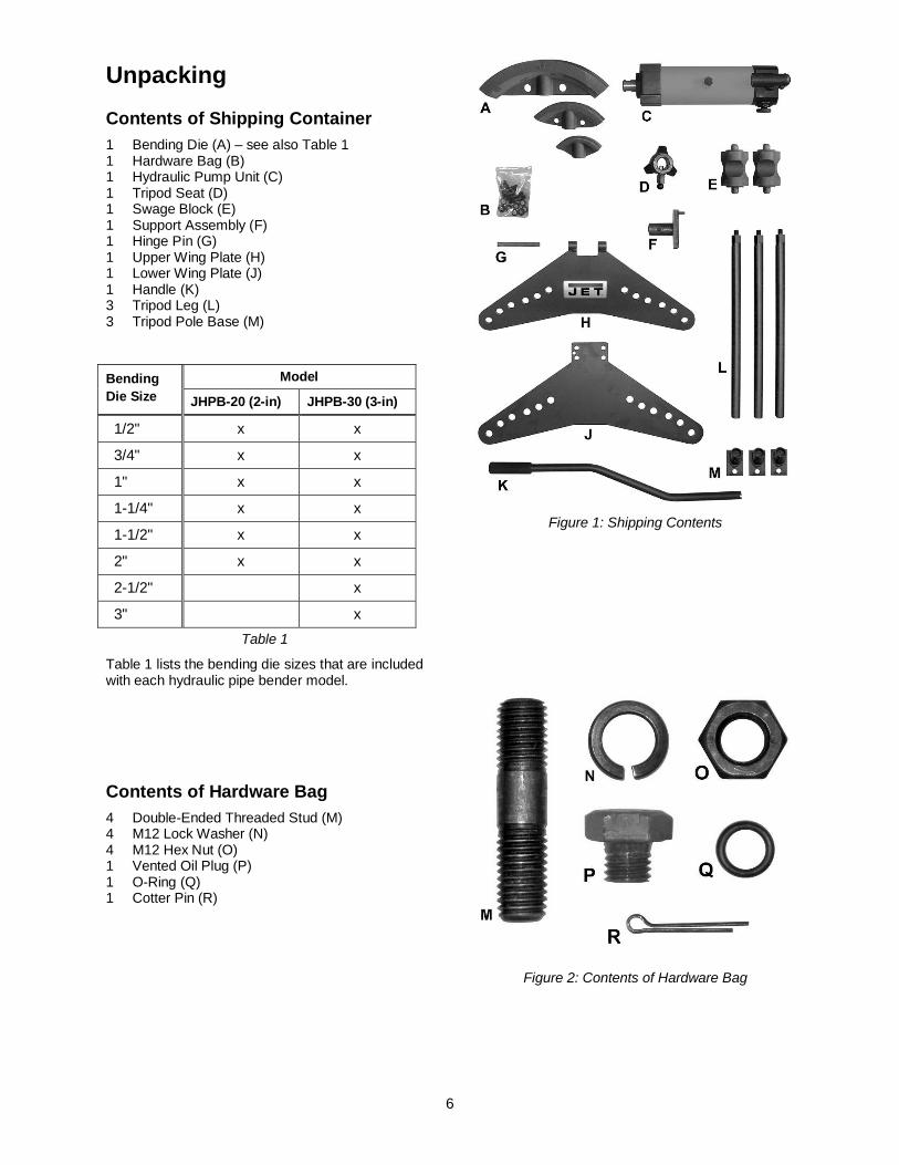
Unpacking
Contents of Shipping Container 1 Bending Die (A) – see also Table 1 1 Hardware Bag (B) 1 Hydraulic Pump Unit (C) 1 Tripod Seat (D) 1 Swage Block (E) 1 Support Assembly (F) 1 Hinge Pin (G) 1 Upper Wing Plate (H) 1 Lower Wing Plate (J) 1 Handle (K) 3 Tripod Leg (L) 3 Tripod Pole Base (M)
Bending Die Size
Model
JHPB-20 (2-in) JHPB-30 (3-in)
01/2" x x
03/4" x x
01" x x
01-1/4" x x
01-1/2" x x
02" x x
02-1/2" x
03" x
Table 1
Table 1 lists the bending die sizes that are included with each hydraulic pipe bender model.
Contents of Hardware Bag 4 Double-Ended Threaded Stud (M) 4 M12 Lock Washer (N) 4 M12 Hex Nut (O) 1 Vented Oil Plug (P) 1 O-Ring (Q) 1 Cotter Pin (R)
Figure 1: Shipping Contents
Figure 2: Contents of Hardware Bag
7
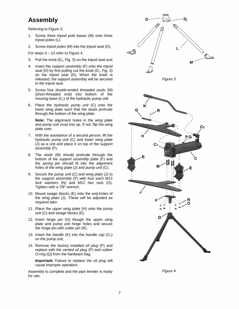
Assembly Referring to Figure 3:
1. Screw three tripod pole bases (M) onto three tripod poles (L).
2. Screw tripod poles (M) into the tripod seat (D).
For steps 3 – 13 refer to Figure 4.
3. Pull the knob (D1, Fig. 3) on the tripod seat and
4. Insert the support assembly (F) onto the tripod seat (D) by first pulling out the knob (D1, Fig. 3) on the tripod seat (D). When the knob is released, the support assembly will be secured to the tripod seat.
5. Screw four double-ended threaded studs (M) (short-threaded end) into bottom of the housing base (C1) of the hydraulic pump unit.
6. Place the hydraulic pump unit (C) onto the lower wing plate such that the studs protrude through the bottom of the wing plate.
Note: The alignment holes in the wing plate and pump unit must line up. If not, flip the wing plate over.
7. With the assistance of a second person, lift the hydraulic pump unit (C) and lower wing plate (J) as a unit and place it on top of the support assembly (F).
8. The studs (M) should protrude through the bottom of the support assembly plate (F) and the spring pin should fit into the alignment holes of the wing plate (J) and pump unit (C).
9. Secure the pump unit (C) and wing plate (J) to the support assembly (F) with four each M12 lock washers (N) and M12 hex nuts (O). Tighten with a 7/8" wrench.
10. Mount swage blocks (E) onto the end-holes of the wing plate (J). These will be adjusted as required later.
11. Place the upper wing plate (H) onto the pump unit (C) and swage blocks (E).
12. Insert hinge pin (G) though the upper wing plate and pump unit hinge holes and secure the hinge pin with cotter pin (R).
13. Insert the handle (K) into the handle cap (C2) on the pump unit.
14. Remove the factory installed oil plug (P) and replace with the vented oil plug (P) and rubber O-ring (Q) from the hardware bag.
Important: Failure to replace the oil plug will cause improper operation.
Assembly is complete and the pipe bender is ready for use.
Figure 3
Figure 4
L
M
D D1
8
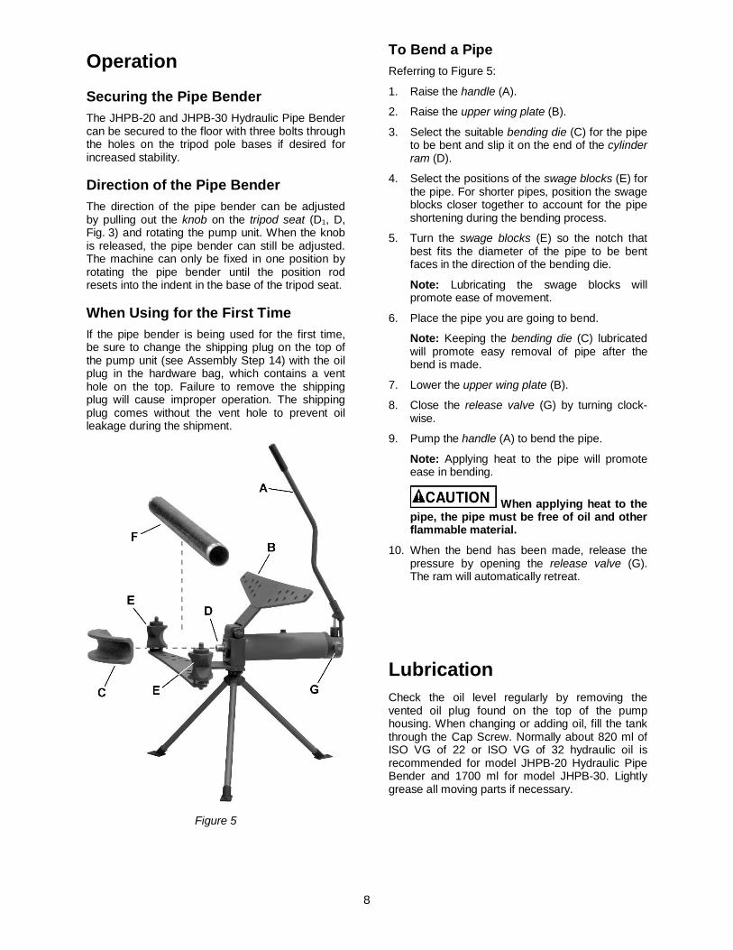
Operation
Securing the Pipe Bender The JHPB-20 and JHPB-30 Hydraulic Pipe Bender can be secured to the floor with three bolts through the holes on the tripod pole bases if desired for increased stability.
Direction of the Pipe Bender The direction of the pipe bender can be adjusted by pulling out the knob on the tripod seat (D1, D, Fig. 3) and rotating the pump unit. When the knob is released, the pipe bender can still be adjusted. The machine can only be fixed in one position by rotating the pipe bender until the position rod resets into the indent in the base of the tripod seat.
When Using for the First Time If the pipe bender is being used for the first time, be sure to change the shipping plug on the top of the pump unit (see Assembly Step 14) with the oil plug in the hardware bag, which contains a vent hole on the top. Failure to remove the shipping plug will cause improper operation. The shipping plug comes without the vent hole to prevent oil leakage during the shipment.
Figure 5
To Bend a Pipe Referring to Figure 5:
1. Raise the handle (A).
2. Raise the upper wing plate (B).
3. Select the suitable bending die (C) for the pipe to be bent and slip it on the end of the cylinder ram (D).
4. Select the positions of the swage blocks (E) for the pipe. For shorter pipes, position the swage blocks closer together to account for the pipe shortening during the bending process.
5. Turn the swage blocks (E) so the notch that best fits the diameter of the pipe to be bent faces in the direction of the bending die.
Note: Lubricating the swage blocks will promote ease of movement.
6. Place the pipe you are going to bend.
Note: Keeping the bending die (C) lubricated will promote easy removal of pipe after the bend is made.
7. Lower the upper wing plate (B).
8. Close the release valve (G) by turning clock-wise.
9. Pump the handle (A) to bend the pipe.
Note: Applying heat to the pipe will promote ease in bending.
When applying heat to the pipe, the pipe must be free of oil and other flammable material.
10. When the bend has been made, release the pressure by opening the release valve (G). The ram will automatically retreat.
Lubrication Check the oil level regularly by removing the vented oil plug found on the top of the pump housing. When changing or adding oil, fill the tank through the Cap Screw. Normally about 820 ml of ISO VG of 22 or ISO VG of 32 hydraulic oil is recommended for model JHPB-20 Hydraulic Pipe Bender and 1700 ml for model JHPB-30. Lightly grease all moving parts if necessary.
To Bend Pipe
9
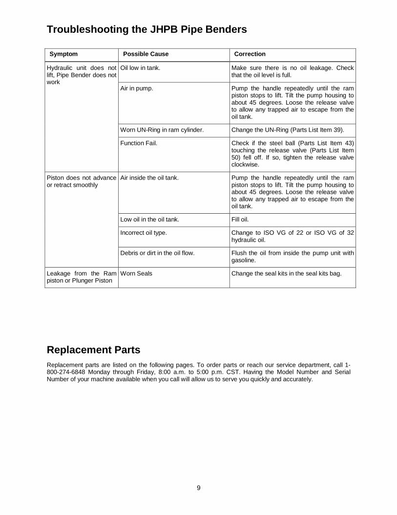
Troubleshooting the JHPB Pipe Benders Symptom Possible Cause Correction
Hydraulic unit does not lift, Pipe Bender does not work
Oil low in tank. Make sure there is no oil leakage. Check that the oil level is full.
Air in pump. Pump the handle repeatedly until the ram piston stops to lift. Tilt the pump housing to about 45 degrees. Loose the release valve to allow any trapped air to escape from the oil tank.
Worn UN-Ring in ram cylinder. Change the UN-Ring (Parts List Item 39).
Function Fail. Check if the steel ball (Parts List Item 43) touching the release valve (Parts List Item 50) fell off. If so, tighten the release valveclockwise.
Piston does not advance or retract smoothly
Air inside the oil tank. Pump the handle repeatedly until the ram piston stops to lift. Tilt the pump housing to about 45 degrees. Loose the release valve to allow any trapped air to escape from the oil tank.
Low oil in the oil tank. Fill oil.
Incorrect oil type. Change to ISO VG of 22 or ISO VG of 32 hydraulic oil.
Debris or dirt in the oil flow. Flush the oil from inside the pump unit with gasoline.
Leakage from the Ram piston or Plunger Piston
Worn Seals Change the seal kits in the seal kits bag.
Replacement Parts Replacement parts are listed on the following pages. To order parts or reach our service department, call 1-800-274-6848 Monday through Friday, 8:00 a.m. to 5:00 p.m. CST. Having the Model Number and Serial Number of your machine available when you call will allow us to serve you quickly and accurately.
10
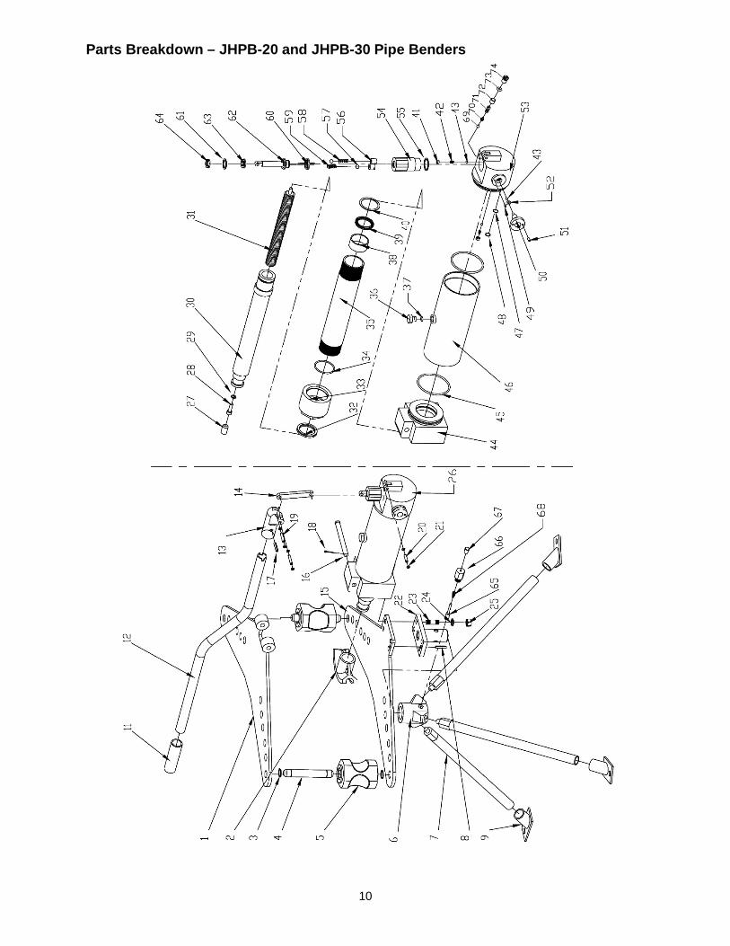
Parts Breakdown – JHPB-20 and JHPB-30 Pipe Benders
11
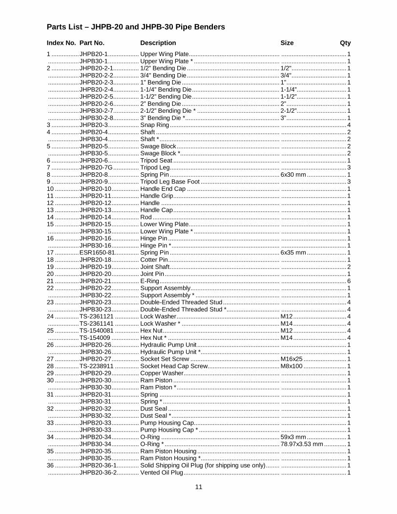
Parts List – JHPB-20 and JHPB-30 Pipe Benders
Index No. Part No. Description Size Qty
1 ................ JHPB20-1 .................. Upper Wing Plate..................................................... ...................................... 1 .................. JHPB30-1 .................. Upper Wing Plate * .................................................. ...................................... 1 2 ................ JHPB20-2-1............... 1/2” Bending Die ...................................................... 1/2" ................................ 1 .................. JHPB20-2-2............... 3/4" Bending Die ...................................................... 3/4" ................................ 1 .................. JHPB20-2-3............... 1” Bending Die ......................................................... 1” ................................... 1 .................. JHPB20-2-4............... 1-1/4” Bending Die ................................................... 1-1/4”............................. 1 .................. JHPB20-2-5............... 1-1/2” Bending Die ................................................... 1-1/2”............................. 1 .................. JHPB20-2-6............... 2” Bending Die ......................................................... 2” ................................... 1 .................. JHPB30-2-7............... 2-1/2” Bending Die * ................................................ 2-1/2”............................. 1 .................. JHPB30-2-8............... 3” Bending Die *....................................................... 3” ................................... 1 3 ................ JHPB20-3 .................. Snap Ring ................................................................ ...................................... 4 4 ................ JHPB20-4 .................. Shaft ........................................................................ ...................................... 2 .................. JHPB30-4 .................. Shaft * ...................................................................... ...................................... 2 5 ................ JHPB20-5 .................. Swage Block ............................................................ ...................................... 2 .................. JHPB30-5 .................. Swage Block *.......................................................... ...................................... 2 6 ................ JHPB20-6 .................. Tripod Seat .............................................................. ...................................... 1 7 ................ JHPB20-7G ............... Tripod Leg................................................................ ...................................... 3 8 ................ JHPB20-8 .................. Spring Pin ................................................................ 6x30 mm ....................... 1 9 ................ JHPB20-9 .................. Tripod Leg Base Foot .............................................. ...................................... 3 10 .............. JHPB20-10 ................ Handle End Cap ...................................................... ...................................... 1 11 .............. JHPB20-11 ................ Handle Grip.............................................................. ...................................... 1 12 .............. JHPB20-12 ................ Handle ..................................................................... ...................................... 1 13 .............. JHPB20-13 ................ Handle Cap .............................................................. ...................................... 1 14 .............. JHPB20-14 ................ Rod .......................................................................... ...................................... 1 15 .............. JHPB20-15 ................ Lower Wing Plate..................................................... ...................................... 1 .................. JHPB30-15 ................ Lower Wing Plate * .................................................. ...................................... 1 16 .............. JHPB20-16 ................ Hinge Pin ................................................................. ...................................... 1 .................. JHPB30-16 ................ Hinge Pin * ............................................................... ...................................... 1 17 .............. ESR1650-81.............. Spring Pin ................................................................ 6x35 mm ....................... 1 18 .............. JHPB20-18 ................ Cotter Pin ................................................................. ...................................... 1 19 .............. JHPB20-19 ................ Joint Shaft ................................................................ ...................................... 2 20 .............. JHPB20-20 ................ Joint Pin ................................................................... ...................................... 1 21 .............. JHPB20-21 ................ E-Ring ...................................................................... ...................................... 6 22 .............. JHPB20-22 ................ Support Assembly.................................................... ...................................... 1 .................. JHPB30-22 ................ Support Assembly * ................................................. ...................................... 1 23 .............. JHPB20-23 ................ Double-Ended Threaded Stud ................................. ...................................... 4 .................. JHPB30-23 ................ Double-Ended Threaded Stud *............................... ...................................... 4 24 .............. TS-2361121 .............. Lock Washer ............................................................ M12 ............................... 4 .................. TS-2361141 .............. Lock Washer * ......................................................... M14 ............................... 4 25 .............. TS-1540081 .............. Hex Nut .................................................................... M12 ............................... 4 .................. TS-154009 ................ Hex Nut * ................................................................. M14 ............................... 4 26 .............. JHPB20-26 ................ Hydraulic Pump Unit ................................................ ...................................... 1 .................. JHPB30-26 ................ Hydraulic Pump Unit *.............................................. ...................................... 1 27 .............. JHPB20-27 ................ Socket Set Screw .................................................... M16x25 ......................... 1 28 .............. TS-2238911 .............. Socket Head Cap Screw.......................................... M8x100 ......................... 1 29 .............. JHPB20-29 ................ Copper Washer........................................................ ...................................... 1 30 .............. JHPB20-30 ................ Ram Piston .............................................................. ...................................... 1 .................. JHPB30-30 ................ Ram Piston * ............................................................ ...................................... 1 31 .............. JHPB20-31 ................ Spring ...................................................................... ...................................... 1 .................. JHPB30-31 ................ Spring * .................................................................... ...................................... 1 32 .............. JHPB20-32 ................ Dust Seal ................................................................. ...................................... 1 .................. JHPB30-32 ................ Dust Seal * ............................................................... ...................................... 1 33 .............. JHPB20-33 ................ Pump Housing Cap.................................................. ...................................... 1 .................. JHPB30-33 ................ Pump Housing Cap * ............................................... ...................................... 1 34 .............. JHPB20-34 ................ O-Ring ..................................................................... 59x3 mm ....................... 1 .................. JHPB30-34 ................ O-Ring * ................................................................... 78.97x3.53 mm ............. 1 35 .............. JHPB20-35 ................ Ram Piston Housing ................................................ ...................................... 1 .................. JHPB30-35 ................ Ram Piston Housing *.............................................. ...................................... 1 36 .............. JHPB20-36-1............. Solid Shipping Oil Plug (for shipping use only) ........ ...................................... 1 .................. JHPB20-36-2............. Vented Oil Plug ........................................................ ...................................... 1
12
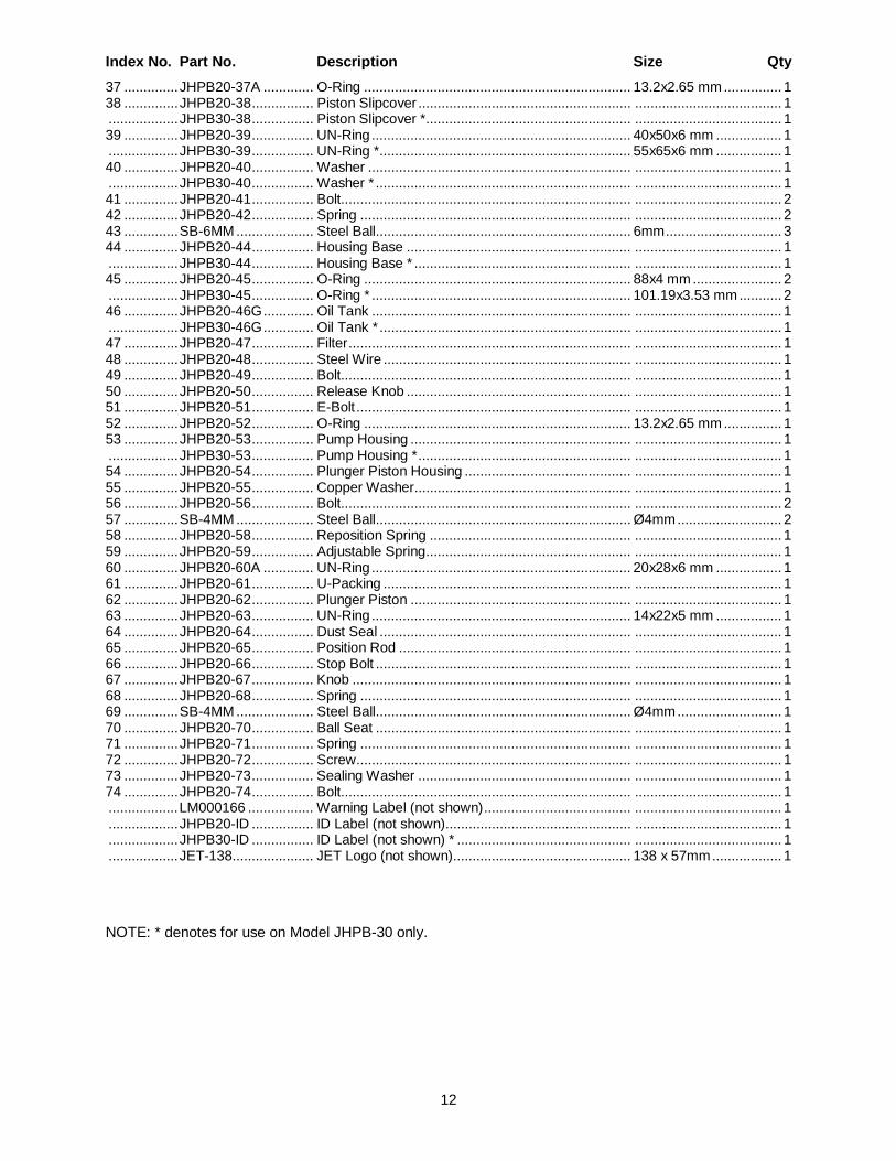
Index No. Part No. Description Size Qty
37 .............. JHPB20-37A ............. O-Ring ..................................................................... 13.2x2.65 mm ............... 1 38 .............. JHPB20-38 ................ Piston Slipcover ....................................................... ...................................... 1 .................. JHPB30-38 ................ Piston Slipcover *..................................................... ...................................... 1 39 .............. JHPB20-39 ................ UN-Ring ................................................................... 40x50x6 mm ................. 1 .................. JHPB30-39 ................ UN-Ring *................................................................. 55x65x6 mm ................. 1 40 .............. JHPB20-40 ................ Washer .................................................................... ...................................... 1 .................. JHPB30-40 ................ Washer * .................................................................. ...................................... 1 41 .............. JHPB20-41 ................ Bolt........................................................................... ...................................... 2 42 .............. JHPB20-42 ................ Spring ...................................................................... ...................................... 2 43 .............. SB-6MM .................... Steel Ball.................................................................. 6mm .............................. 3 44 .............. JHPB20-44 ................ Housing Base .......................................................... ...................................... 1 .................. JHPB30-44 ................ Housing Base * ........................................................ ...................................... 1 45 .............. JHPB20-45 ................ O-Ring ..................................................................... 88x4 mm ....................... 2 .................. JHPB30-45 ................ O-Ring * ................................................................... 101.19x3.53 mm ........... 2 46 .............. JHPB20-46G ............. Oil Tank ................................................................... ...................................... 1 .................. JHPB30-46G ............. Oil Tank * ................................................................. ...................................... 1 47 .............. JHPB20-47 ................ Filter ......................................................................... ...................................... 1 48 .............. JHPB20-48 ................ Steel Wire ................................................................ ...................................... 1 49 .............. JHPB20-49 ................ Bolt........................................................................... ...................................... 1 50 .............. JHPB20-50 ................ Release Knob .......................................................... ...................................... 1 51 .............. JHPB20-51 ................ E-Bolt ....................................................................... ...................................... 1 52 .............. JHPB20-52 ................ O-Ring ..................................................................... 13.2x2.65 mm ............... 1 53 .............. JHPB20-53 ................ Pump Housing ......................................................... ...................................... 1 .................. JHPB30-53 ................ Pump Housing * ....................................................... ...................................... 1 54 .............. JHPB20-54 ................ Plunger Piston Housing ........................................... ...................................... 1 55 .............. JHPB20-55 ................ Copper Washer........................................................ ...................................... 1 56 .............. JHPB20-56 ................ Bolt........................................................................... ...................................... 2 57 .............. SB-4MM .................... Steel Ball.................................................................. Ø4mm ........................... 2 58 .............. JHPB20-58 ................ Reposition Spring .................................................... ...................................... 1 59 .............. JHPB20-59 ................ Adjustable Spring..................................................... ...................................... 1 60 .............. JHPB20-60A ............. UN-Ring ................................................................... 20x28x6 mm ................. 1 61 .............. JHPB20-61 ................ U-Packing ................................................................ ...................................... 1 62 .............. JHPB20-62 ................ Plunger Piston ......................................................... ...................................... 1 63 .............. JHPB20-63 ................ UN-Ring ................................................................... 14x22x5 mm ................. 1 64 .............. JHPB20-64 ................ Dust Seal ................................................................. ...................................... 1 65 .............. JHPB20-65 ................ Position Rod ............................................................ ...................................... 1 66 .............. JHPB20-66 ................ Stop Bolt .................................................................. ...................................... 1 67 .............. JHPB20-67 ................ Knob ........................................................................ ...................................... 1 68 .............. JHPB20-68 ................ Spring ...................................................................... ...................................... 1 69 .............. SB-4MM .................... Steel Ball.................................................................. Ø4mm ........................... 1 70 .............. JHPB20-70 ................ Ball Seat .................................................................. ...................................... 1 71 .............. JHPB20-71 ................ Spring ...................................................................... ...................................... 1 72 .............. JHPB20-72 ................ Screw ....................................................................... ...................................... 1 73 .............. JHPB20-73 ................ Sealing Washer ....................................................... ...................................... 1 74 .............. JHPB20-74 ................ Bolt........................................................................... ...................................... 1 .................. LM000166 ................. Warning Label (not shown) ...................................... ...................................... 1 .................. JHPB20-ID ................ ID Label (not shown)................................................ ...................................... 1 .................. JHPB30-ID ................ ID Label (not shown) * ............................................. ...................................... 1 .................. JET-138..................... JET Logo (not shown).............................................. 138 x 57mm .................. 1
NOTE: * denotes for use on Model JHPB-30 only.