operating instructions k-powergrip ewl 4941
TRANSCRIPT

Operating InstructionsK-POWERgrip EWL 4941.
Always on the safe site.

KaVo Elektrotechnisches Werk GmbHWangener Straße 78D-88299 Leutkirch

1
K-POWERgrip EWL 4941.
A 1 User information ................................................................................................................................................................2A 1.1 Meaning of the pictograms ..........................................................................................................................................2A 1.2 Important information ..................................................................................................................................................2A 1.3 Precautions ..................................................................................................................................................................2A 1.4 Purpose and applications ............................................................................................................................................3A 1.5 Technical data ..............................................................................................................................................................3
A 2 Scope of delivery - accessory ..........................................................................................................................................4A 2.1 Scope of delivery ........................................................................................................................................................4A 2.2 Accessory ....................................................................................................................................................................4
A 3 Description ..........................................................................................................................................................................4
A 4 Preparations for commencing operation ..........................................................................................................................5A 4.1 Commencing operation ................................................................................................................................................5
A 5 Operation ............................................................................................................................................................................5A 5.1 Inserting / changing the tool ........................................................................................................................................5A 5.2 Operation ....................................................................................................................................................................5
A 6 Maintenance ........................................................................................................................................................................6A 6.1 Weekly cleaning of chuck and handpiece part ............................................................................................................6A 6.2 Replacing the ball bearings ........................................................................................................................................7A 6.3 Changing connecting cable ........................................................................................................................................9
A 7 Malfunctions ......................................................................................................................................................................10
Spare parts ..........................................................................................................................................................................12Guarantee conditions ..........................................................................................................................................................14EC- Declaration of conformity ..............................................................................................................................................15

2
K-POWERgrip EWL 4941.
KaVo assumes no responsibility for damagearising through:
• external influences (poor quality of themedia or inadequate installation)
• use of incorrect information• improper use• improperly performed repairs.
Repair and maintenance work - apart fromthe activities described in these instructionsfor use - may be performed only by quali-fied technical personnel.
In the event of modifications by third par-ties, the approvals become null and void.KaVo recommends using only originalspare parts for operation and for repair.
A 1.3 Precautions
Safe operation and protection of the unit areensured only through proper use in accor-dance with the instructions for use andusing the tools approved for the purpose.The following should also be observed:
• the tool manufacturer's instructions, • the work safety regulations,• the accident prevention regulations.
■ Each time before switching on, check theset speed.■ Observe the permissible maximum speedand maximum pressure of the tools(according to tool manufacturer'sinstructions).■ Use safety screens when working withrotating tools.■ To avoid danger through accidentalswitching on, place the handpiece on asuitable shelf or tool support.
In the event of an unsatisfactory conditionof the unit or improper use, e.g.:
• unsuitable tools• tool shafts not manufactured according to
DIN-ISO• improper use or use not in accordance
with the purpose• unapproved speeds for tools used• incorrect clamping of the tools in the
chuck• insufficient retaining force of the chuck
(wear, soiling, failure to follow the prod-uct care instructions for the chuck system,etc.)
• different sizes of tool shaft and chuck • lack of regular cleaning of the chuck• failure to follow the maintenance instruc-
tions• failure to comply with the accident pre-
vention regulations (e.g. failure to usesafety screens, safety devices, handpiecesupports, etc.)
• failure to take into account signs of wearand damage
• tool shafts which have slipped out (poten-tial danger = bending of the tool shafts)
there is a danger of injury and damage tomaterial and unit, e.g. due to:
• Bending of the tool shafts• Accidental withdrawal of the tools from
the chuck• Breaking or splintering of the tool.
A 1 User information
A 1.1 Meaning of the pictograms
Situations where failure to follow theinstructions may lead to danger,
damage to material or operating faults.
Important information for operatorand engineer.
Automatic modeAutomatic sequence
Close, screw in, fasten, etc.
Open, release, loosen
+ more, higher
- less, lower
∞ Continuous operation
Time, time sequence
Disconnect mains plug
A 1.2 Important information
The instructions for use should beread by the user before starting up
the unit for the first time, in order to avoidincorrect operation and other damage. Ifother language versions are required,please request these from your responsibleKaVo agent. Duplication and distributionof the instructions for use (IU) requireKaVo's prior consent.
All technical data, information and proper-ties of the product described in the IU cor-respond to the state on going to press.
Modifications and improvements to theproduct as a result of new technical devel-opments are possible.
This does not imply any right to retrofittingof existing units.

3
K-POWERgrip EWL 4941.
A 1.4 Purpose and applications
K-POWERgrip EWL 4941 handpieces areversatile and very particularly suitable forworking on crowns and bridges.
A 1.5 Technical data
K-POWERgrip type EWL 4941
Length: 165 mm
Handpiece part: max. ∅ 29 mm
Motor part: max. ∅ 28 mm
Weight: approx. 250 gwith connecting cable approx. 355 g
Output power max. 150 wattmax. 7 Ncm
Speed range 1,000-50,000 min-1
Pollution level: 2
Overvoltage category: ll
Ambient conditions:
Permitted in interior rooms
Permissible ambient temperature range of 5° C - 40° C
Permitted to max. relative humidity 80%
We reserve the right to make technicalmodifications.
4
K-POWERgrip EWL 4941.
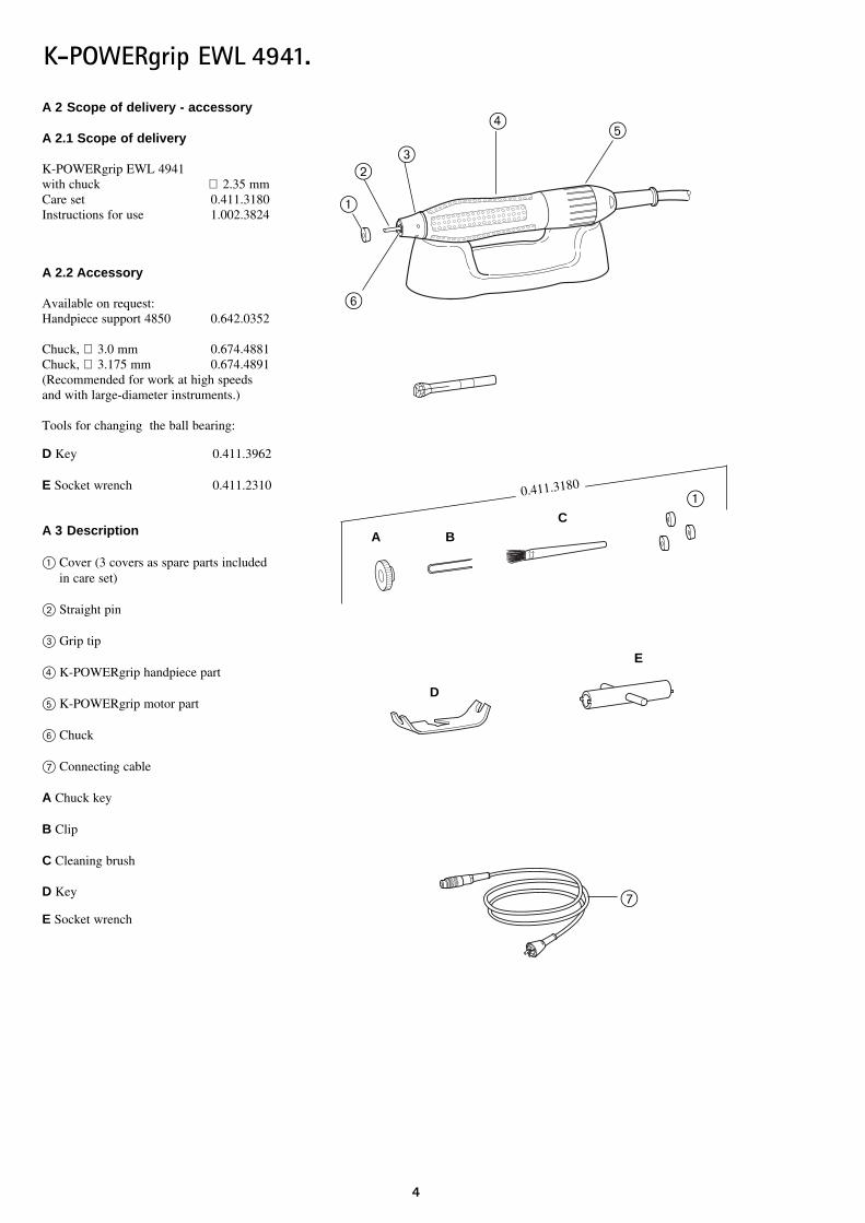
A 2 Scope of delivery - accessory
A 2.1 Scope of delivery
K-POWERgrip EWL 4941with chuck ∅ 2.35 mmCare set 0.411.3180Instructions for use 1.002.3824
A 2.2 Accessory
Available on request:Handpiece support 4850 0.642.0352
Chuck, ∅ 3.0 mm 0.674.4881Chuck, ∅ 3.175 mm 0.674.4891(Recommended for work at high speedsand with large-diameter instruments.)
Tools for changing the ball bearing:
D Key 0.411.3962
E Socket wrench 0.411.2310
A 3 Description
@ Cover (3 covers as spare parts includedin care set)
” Straight pin
# Grip tip
£ K-POWERgrip handpiece part
fi K-POWERgrip motor part
Ì Chuck
\ Connecting cable
A Chuck key
B Clip
C Cleaning brush
D Key
E Socket wrench
D
E
0.411.3180
A BC
@
”#
£
@
Ì
fi
\
5
K-POWERgrip EWL 4941.
A 4 Preparations for commencingoperation
Do not operate or lay down your K-POWERgrip handpiece EWL
4941, unless an instrument or the test pin isclamped in the chuck. When the chuck isopen, the K-POWERgrip handpiece, is locked, andinadvertent use will cause the K-Control control unit to switch to malfunction. Malfunction indicator lightsup or begins to flash.
A 4.1 Commencing operation
The K-POWERgrip handpiece EWL 4941can be operated with the K-Controll unit:
Knee-operated control unit EWL 4960benchtop-control unit EWL 4965Foot-control unit EWL 4970
A 5 Operation
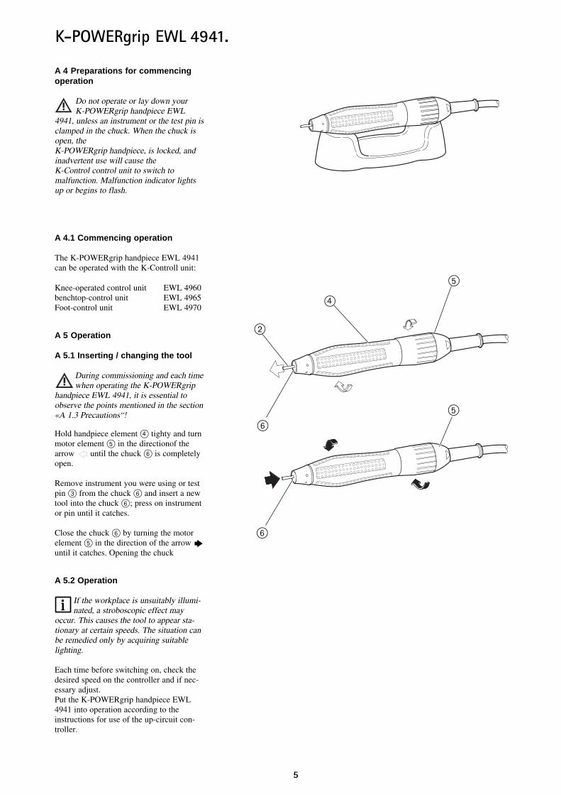
A 5.1 Inserting / changing the tool
During commissioning and each timewhen operating the K-POWERgrip
handpiece EWL 4941, it is essential toobserve the points mentioned in the section«A 1.3 Precautions“!
Hold handpiece element £ tighty and turnmotor element fi in the directionof thearrow until the chuck Ì is completelyopen.
Remove instrument you were using or testpin # from the chuck Ì and insert a newtool into the chuck Ì; press on instrumentor pin until it catches.
Close the chuck Ì by turning the motorelement fi in the direction of the arrow until it catches. Opening the chuck
A 5.2 Operation
If the workplace is unsuitably illumi-nated, a stroboscopic effect may
occur. This causes the tool to appear sta-tionary at certain speeds. The situation canbe remedied only by acquiring suitablelighting.
Each time before switching on, check thedesired speed on the controller and if nec-essary adjust.Put the K-POWERgrip handpiece EWL4941 into operation according to theinstructions for use of the up-circuit con-troller.
Ì
£
”
fi
fi
Ì

6
K-POWERgrip EWL 4941.
A 6 Maintenance
■ Repair and maintenance work on theelectrical part of the unit may be performedonly by qualified technical personnel ortrained persons who have been made awareof the safety regulations. Beforemaintenance work, disconnect the mainsplug or isolate the unit completely from thepower supply so that there is no power tothe unit.■ On no account may the K-POWERgriphandpiece EWL 4941 be cleaned withcompressed air; use the cleaning brushfrom the care set.■ On no account should cleaning agents(such as spray cleaner, degreaser, etc.) beintroduced into the interior of thehandpiece.■ using original chuck key A
A 6.1 Weekly cleaning of chuck andhandpiece part
Removing the chuck
Remove previously used tool or straightpin from chuck and take off cover @ (3 covers as spare parts in care set).
Push tool or straight pin into chuck as faras it will go and close chuck.
Slowly turn the shaft ” until clip B can beinserted into grip tip # with little resist-ance.
Open the chuck. Unscrew the chuck usingoriginal chuck key A and inserted straightpin or tool ”.
Clean the front opening of the K-POWERgrip handpiece EWL 4941 witha brush or with the cleaning brushsupplied. Clean chuck thread, surface ofthe original chuck A and rotor cone andlightly grease.
Installing the chuck
Insert chuck incl. straight pin ” usingoriginal chuck key A and tighten.
Mount cover @ again.
Remove clip B from grip tip # and closechuck with inserted straight pin again.
Cl ea n e r
” @
A
@
B
#
Ì
Ì
”
#
£
”
A
B

7
K-POWERgrip EWL 4941.
A 6.2 Replacing the ball bearings
Dismantling
Slowly turn the shaft by the straight pin ”until clip B can be inserted into grip tip #with little resistance..
Loosen grip tip in direction of arrow and remove clip.
Completely unscrew grip tip and removefelt washer \.
Grip handpiece part £ and loosen thread-ed ring | with socket wrench E andunscrew.
Remove complete shaft unit · from K-POWERgrip handpiece EWL 4941.
Remove ball bearing ¯ and bush » fromshaft.
Hold shaft with key D and loosen nut „with socket wrench E - Note left-handedthread.
Remove nut „ with ball bearing ‰ fromshaft.
|
”
#
£E
B
E
D
¯ »
„‰
\
·
„

8
K-POWERgrip EWL 4941.
Assembly
Push new ball bearing ‰ onto shaft. Holdshaft with key D and screw on nut „again with socket wrench E - note the left-handed thread.
Push ball bearing ¯ (with the two O-ringsfacing the inside of the handpiece) andbush » onto the shaft as far as it will go.
While rotating the shaft unit ·, insert itinto the K-POWERgrip handpiece EWL4941.
Grip handpiece part £ and tighten thethreaded ring | with socket wrench E.
Insert new felt washer \ into threadedring |.
Hold K-POWERgrip handpiece EWL4941, screw on grip tip by hand and tightencarefully with clip B. Insert cover @.
To increase the life of the ball bear-ing, KaVo EWL recommends:
After changing the ball bearing, allow thehandpiece to run without an inserted instru-ment for about 60 minutes at 10,000 to15,000 min -1.
¯ »
·
£
E
D
|
\
@
‰ „
E
B
|

9
K-POWERgrip EWL 4941.
A 6.3 Changing connecting cable
Unscrew the connecting cap » from theK-POWERgrip-Motor element fi and pullout the connection cable ‰ in the directionof the arrow .
Insert new connecting cable ‰ (3-pin)completely into motor part fi and screwon connecting cap » again. »fi
fi „»
‰
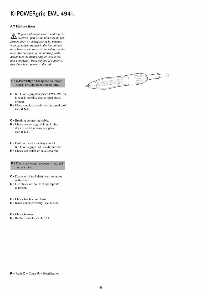
A 7 Malfunctions
Repair and maintenance work on theelectrical part of the unit may be per-
formed only by specialists or by personswho have been trained in the factory andhave been made aware of the safety regula-tions. Before opening the housing parts,disconnect the mains plug or isolate theunit completely from the power supply sothat there is no power to the unit.
C • K-POWERgrip handpiece EWL 4941 isblocked, possibly due to open chuck system.
R • Close chuck correctly with inserted tool(see A 5.1).
C • Break in connecting cable.R • Check connecting cable incl. plug
devices and if necessary replace (see A 6.3).
C • Fault in the electrical system of K-POWERgrip EWL 4941controller.
R • Check controller or have repaired.
C • Diameter of tool shaft does not agree with chuck.
R • Use chuck or tool with appropriate diameter.
C • Chuck has become loose.R • Insert chuck correctly (see A 6.1).
C • Chuck is worn.R • Replace chuck (see A 6.1).
F = Fault C = Cause R = Rectification
F • Tool is no longer adequately retained in the chuck.
F • K-POWERgrip handpiece no longer rotates or stops from time to time.
10
K-POWERgrip EWL 4941.

C • Ball bearing faulty owing to wear or soiling.
R • Check ball bearing and if necessary replace.(see A 6.2)
C • Prolonged operation under very high load.
R • Eliminate cause of high load, if neces-sary increase speed or use tools with smaller diameter.
C • Electronics of controller faulty.R • Check controller or have repaired.
F = Fault C = Cause R = Rectification
F • Loud running noise or K-POWERgrip handpiece EWL 4941 heats up
11
K-POWERgrip EWL 4941.

Spare parts
12
K-POWERgrip EWL 4941.
0.202.0021
0.200.08360.200.0837
0.201.8083
0.674.4861
A
B
C
0.674.79420.222.4018
0.200.6095
1.002.3648
0.200.6219
1.002.3600
0.200.6320
0.674.4701
0.200.6155
0.674.8962
0.674.8982
0.220.0778
0.220.0779
B
POWERgrip
1.002.3644
0.674.8472
0.223.0111
0.223.0396
1.001.6751
0.224.7048
0.674.7392
0.200.1045
0.223.0082
0.070.3274 ø 5 mm*m
POWERgrip
0.200.6093

13
K-POWERgrip EWL 4941.
0.674.9012
0.200.6220
0.200.6199
0.674.4172
1.002.2896
0.674.4162
0.674.4152
0.674.8752
0.674.4511
0.200.6095
0.220.0044
0.674.7602
0.200.6303
0.674.7642
0.674.8732
0.674.9002
0.200.0826
1.000.3586
0.674.8772
0.222.4044
0.200.1252
0.674.4871 ø 2,35 mm 0.674.4881 ø 3,0 mm 0.674.4891 ø 3,175 mm
0.202.0021
0.674.8212 ø 2,35 mm / ø 3,00 mm 0.674.8482 ø 3,175 mm
A
0.200.6323
1.000.1260

14
K-POWERgrip EWL 4941.
Guarantee conditions
Under valid KaVo EWL delivery and payment conditions, KaVo EWL gives a guarantee of satisfactory function and freedom from faultsin material and manufacture for the duration of 6 months from the date of sale certified by the vendor. After expiry of the warranty, KaVogives a guarantee of another 6 months for damage attributable to deficiencies in the material or in manufacture.In the case of justifiable complaints, KaVo EWL shall supply spare parts or carry out repairs free of charge. KaVo EWL accepts noliability for defects and their consequences which have arisen or could have arisen as a result of natural wear, improper handling, cleaningor maintenance, noncompliance with the maintenance, operating and connecting instructions, corrosion, impurities in the air supply orchemical or electrical influences which are unusual or not admissible in accordance with KaVo's instructions. The guarantee shall becomenull and void if defects or their consequences can be attributed to interventions in or modifications to the product. Guarantee claims canonly be validated if they are notified immediately in writing to KaVo EWL.

EC- Declaration of conformity
15
K-POWERgrip EWL 4941.

1.00
2.38
24●
RB
●05
/03
●G
B ●
01
.40
DD--8888229999 LLEEUUTTKKIIRRCCHH..TTeelleeffoonn 00 7755 6611//8866--115500 ·· FFaaxx 00 7755 6611//8866--226655
IInntteerrnneett:: wwwwww..kkaavvoo..ccoomm