operating instructions - the paul n. gardner company · included with operating instructions and a...
TRANSCRIPT
wa-varspeedpneumaticINSTR REV 04/24/07�
GARDCO WASHABILITY, WEAR &FRICTION TESTER
OperatingInstructions
Pneumatic VaRiaBLe SPeeD mODeL (VP)
316 N.E. FIRST ST • POMPANO BEACH, FL 33060P.O. BOX 10688 • POMPANO BEACH, FL 33061-6688PHONE 1-800-762-2478 • (954) 946-9454 • FAX (954) 946-9309www.gardco.com • [email protected]
COMPANY INCORPORATEDGARDNERPAUL N.

cu
sto
m
ship
pin
g c
ar
ton
do
no
t d
isc
ar
d
oV
Er
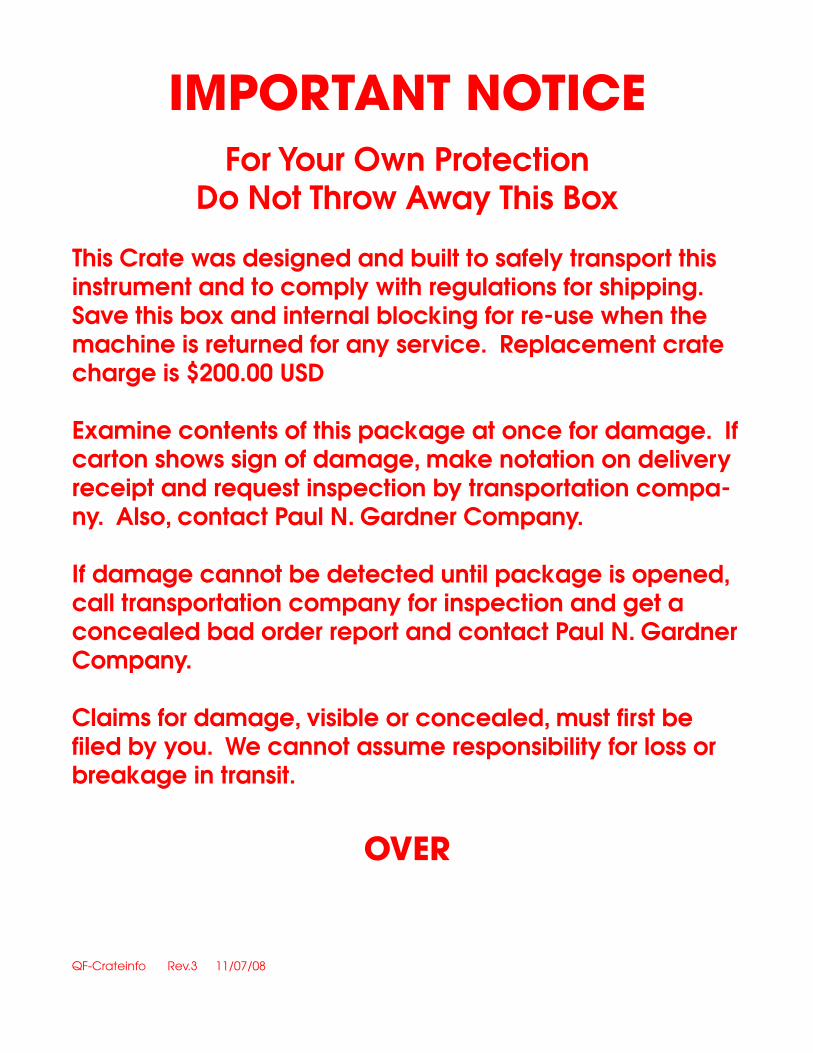
important noticEFor Your Own Protection
Do Not Throw Away This Box
This Crate was designed and built to safely transport this instrument and to comply with regulations for shipping.Save this box and internal blocking for re-use when the machine is returned for any service. Replacement crate charge is $200.00 USD Examine contents of this package at once for damage. If carton shows sign of damage, make notation on delivery receipt and request inspection by transportation compa-ny. Also, contact Paul N. Gardner Company.
If damage cannot be detected until package is opened, call transportation company for inspection and get a concealed bad order report and contact Paul N. Gardner Company.
Claims for damage, visible or concealed, must first be filed by you. We cannot assume responsibility for loss or breakage in transit.
oVEr
QF-Crateinfo Rev.3 11/07/08

wa-varspeedpneumaticINSTR REV 04/24/072
GARDCOFRICTION - WEAR - WASHABILITYLINEAR MOTION TEST EQUIPMENT
OPERATING INSTRUCTIONSMODEL D10VP
These instructions cover operation of the Gardco Linear Motion Equipment only. For test sample preparation and for use of machine auxiliaries with these samples refer to the appropriate standard method of test listed under Specification Refer-ences of the product leaflet for this equipment.
Warning: Do not remove component case cover without first removing the unit electrical cord from the power outlet. As long as the unit is connected to the power outlet there are internal hot terminals even though the “power” switch is in the off position. If it is necessary to make component adjustments with the unit running it should be done only by a qualified electrician and one who is skilled in working in areas of unguarded pinch points. A system electrical diagram is included with operating instructions and a copy is contained in the cover of the component case cover.
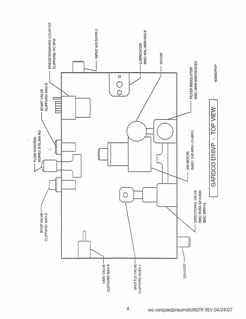
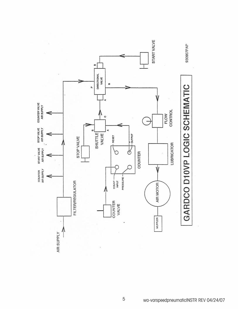
1. Connect an air supply via 1/4” NPT bulkhead fitting on the left side of the machine. Be sure to hold hex on bulkhead from turning when tightening attaching fitting.
2. Connect an external exhaust line or supplied muffler via 1/4” NPT bulkhead fitting on the right rear of the machine. Be sure to hold hex on bulkhead from turning when tightening attaching fitting.
3. To set the predetermining counter for the desired number of cycles, press and hold the black button on the left hand side of the counter display and index the counter setting by pushing buttons below each digit on counter.
4. To set the number of cycles per minute the unit is to operate at for a particular test, turn the black knob on the front panel (flow control valve) counterclockwise to increase speed or clockwise to decrease speed. Use the following table to set the desired number of cycles/minute (table can be inaccurate if air supply is inadequate). Each full revolution of the dial is equal to 25 divisions. Dial Setting Cycles/Minute 11 15 25 23 150 37 300 44

wa-varspeedpneumaticINSTR REV 04/24/07�
5. Secure the item to be evaluated in test position in accordance with appropriate standard procedure.
6. Depress the green start button on front panel of unit to start the test. The unit will cycle until the counter reaches the value set in step 2 and turn off automatically. The red stop button can be depressed to pause or stop test (counter will not reset so test may be continued).
7. To start another test with the same number of cycles, press the black button to the left of the counter display and counter will reset to the number of cycles set in step 2.
8. To start another test with a different number of cycles, repeat step 2.
GARDCOFRICTION - WEAR - WASHABILITYLINEAR MOTION TEST EQUIPMENT
OPERATING INSTRUCTIONSMODEL D10VP
GARDCO MODEL D10VPMAINTENANCE
Following each series of tests, clean the machine so that it is ready for future use. Any auxiliary used should be removed from the drive fork, cleaned and stored on its side. This is particularly important with the Brush Box with Brush in order to preserve the initial straight conditions of the bristles.
All Gardco Linear Motion Machines are ruggedly designed and require a mini-mum of maintenance. However, it is suggested that each year or following each 2000 hours of operation, the chain should be oiled. This can best be done with the use of an artist brush by brushing oil directly on the chain rollers. A drop or two of oil should be placed on the parallel bars and at each end of the “tail” sprocket bearings. Every 100 hours of operation the Filter Regulator Lubricator should be purged of accumulated moisture and lubricant should be added if necessary. Note: These maintenance procedures should be made only by ex-perienced qualified personnel.
wa-varspeedpneumaticINSTR REV 04/24/074
wa-varspeedpneumaticINSTR REV 04/24/07�

wa-varspeedpneumaticINSTR REV 04/24/07�
BRUSH BRISTLE CHARACTERISTICS
A REPORT FOR
PAUL N. GARDNER COMPANY
MAYNARD R. EUVERARD AUGUST 22, 1992
wa-varspeedpneumaticINSTR REV 04/24/077
A REPORT BYMaynard R. Euverard
August 22, 1992
BRUSH BRISTLE CHARACTERISTICS
TESTING MACHINE
Very rough sandpaper was secured in the right end of the machine Tray with two sided pressure sensitive tape. Sandpaper used was 3M 36S R2. The sandpaper was cut to the width of the Tray and to a length that provided a half inch of brush travel after the brush was completely on the sandpaper.A preliminary investigation indicated that additional weight on the Brush Box exceed-ing two pounds caused the ASTM Brush to “fall to the side” when slowly pulled on just the Stainless Steel Tray. It was also learned that two pounds added to the Brush Box with the “Used” brush would stall the movement of the drive fork with the brush on the sandpaper. Note that the cycle rate chosen was considerably lower than recom-mended for this testing machine. As a result of this preliminary work it was decided to conduct tests on all four brushes without any auxiliary weight on the brush box and on the two new Gardco brushes with two pounds added.
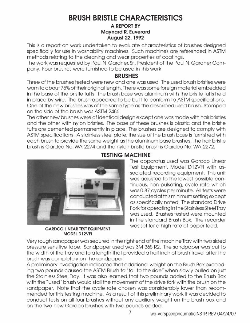
The apparatus used was Gardco Linear Test Equipment, Model D12VFI with as-sociated recording equipment. This unit was adjusted to the lowest possible con-tinuous, non pulsating, cycle rate which was 0.87 cycles per minute. All tests were conducted at this minimum setting except as specifically noted. The standard Drive Fork for operating in the Stainless Steel Tray was used. Brushes tested were mounted in the standard Brush Box. The recorder was set for a high rate of paper feed.
GARDCO LINEAR TEST EQUIPMENTMODEL D12VFI
This is a report on work undertaken to evaluate characteristics of brushes designed specifically for use in washability machines. Such machines are referenced in ASTM methods relating to the cleaning and wear properties of coatings.The work was requested by Paul N. Gardner, Sr., President of the Paul N. Gardner Com-pany. Four brushes were furnished to be used in this work.
BRUSHESThree of the brushes tested were new and one was used. The used brush bristles were worn to about 75% of their original length. There was some foreign material embedded in the base of the bristle tufts. The brush base was aluminum with the bristle tufts held in place by wire. The brush appeared to be built to conform to ASTM specifications.One of the new brushes was of the same type as the described used brush. Stamped on the side of the brush was ASTM 2486.The other new brushes were of identical design except one was made with hair bristles and the other with nylon bristles. The base of these brushes is plastic and the bristle tufts are cemented permanently in place. The brushes are designed to comply with ASTM specifications. A stainless steel plate, the size of the brush base is furnished with each brush to provide the same weight as the aluminum base brushes. The hair bristle brush is Gardco No. WA-2274 and the nylon bristle brush is Gardco No. WA-2272.

wa-varspeedpneumaticINSTR REV 04/24/07�
THE TEST
The Brush Box was positioned at increased speed, when traveling from left to right to about a half inch from the brush entering the sandpaper and the speed was then re-duced to the set minimum and at the same time the recorder was started. As soon as the machine registered a cycle count, near the end of the stroke at near the furthest travel to the right of the fork, a mark was placed on the recorder chart. The machine was permitted to continue in operation until it had moved the brush back onto the stainless Tray surface, clearing the sandpaper by about a half inch at which time the Recorder and Fork travel were stopped.A schematic of the recorder plot is shown in the attached computer drawing. This schematic also shows the measurements and calculations used for the data entered in the attached table.On first study the element that appeared to be most consistent and also easiest to measure was the slope of the plot as the brush decelerated at the end of the stroke. Data was then entered in columns 1 and 2 of the attached table in order of highest to lowest “leading Slope” (most flexible to least flexible bristles). The spread in data is almost three to one giving good resolution in the measurement. Note that the addi-tional weight on the Gardco brushes did not change their order and changed very little their values.Leading slope distance as a percent of left to right brush travel on the sandpaper is shown in column 3 of the table. There is the same relative order as in column 2 but the spread in values is somewhat smaller.It was noted that the “trailing slope” of the recordings in all cases was much greater than the “leading slope”. Why should this be? It also reverses the order of the new Gardco brushes and this is confirmed in both brush loadings but the ASTM brush is still by far the most flexible. A possible explanation is as the brush travels from left to right, the bristles align and nest uniformly as they pass over the edge of the sandpaper.They retain this alignment throughout the left to right travel. At the end of the stroke, the individual bristles straighten and then start to flex in the opposite directions, without the earlier imposed alignment and nesting. Uneven bristle length could increase this effect. Column 4 shows the very much larger values of the trailing slope.Column 5 of the attached table, Trailing Slope as Percent of total right to left travel of the brush on the sandpaper, as would be expected, places the brushes in the same order as column 4 but with an exaggerated difference between the new Gardco brushes.Data in column 5 led to the calculation of the ratio of the leading and trailing slopes. Results are shown in column 6. Here, again, we have the exaggerated reversal of the new Gardco brushes and confirmed with both brush loadings. This leads me to believe that we are seeing a large difference of interfacial friction between these brushes and the sandpaper or a different packing of the individual fibers or range of fiber size.Another element that can be observed in these tests is the force to move the brush over the sandpaper both in the left to right and in the right to left directions. The sum of these forces, without regard to sign, is shown in column 7. Here, the value is less for the more flexible ASTM brush than the two new Gardco brushes. The used brush with shorter bristles showing the greatest force. It is also noted in this column the effect of the additional weight on the Gardco brushes and that the additional weight caused a reversal in their listing order.
wa-varspeedpneumaticINSTR REV 04/24/07�
Finally, the force direction ratio was calculated and listed in column 8 of the attached table. In all cases, the force was greater with the motion from left to right than the motion from right to left. If the argument given above for the data in column 4 is valid, it may also apply to the results in column 8. An important observation is that this dif-ference in column 8 largely disappeared on the new Gardco brushes as the load on the brushes was increased.
DATA INTERPRETATIONCare should be exercised in the interpretation of this preliminary data. In order to obtain apparent constant movement of the drive fork with the “used” brush in place it was necessary to increase the rate dial setting from 1.7 to 2.3. This is proportional to an unloaded cycle rate increase from 0.87 to about 2.4 cycles per minute. It is also possible that there were small undetected cycle rate variations in the testing of other brushes. It was this possibility that led to the use of ratios and percent of totals in the data of the attached table as this procedure minimizes such variations.
RECOMMENDATIONSFrom what has been learned, I suggest the following for future additional investigations: Set the Linear Motion Machine to operate no slower than 2 cycles per second. Use a somewhat less course sandpaper than used in this series of tests. Wherever possible, use a one pound auxiliary weight on the brush box. Report values as shown in columns 3 for bristle stiffness and in column 5 for possible other attributes of the bristles. It is probably not necessary to mark the chart when the machine registers a completed cycle as the change from a positive force to a negative force on the recording looks to be more accurate.A copy of two of the tape recordings is attached to this report. This should be of value for machine setup in any future work.
SUMMARYIn summary, the equipment used is definitely capable of measuring comparative brush bristle stiffness. Data obtained indicates that there is capability of measuring other brush characteristics but additional work would be required for establishing the meaning of all the recorded data. This report is in considerable detail to assist anyone who may conduct further investigations.For further information on the Model D12VFI Gardner Machine used in this report, phone or write to:
Paul N. Gardner Company, Inc. 316 N.E. First Street Pompano Beach, Florida 33060 Phone: 1-800-762-2478 Fax: 954-946-9309

wa-varspeedpneumaticINSTR REV 04/24/07�0
wa-varspeedpneumaticINSTR REV 04/24/07��
WASHABILITY TESTING EQUIPMENTCHARACTERISTICS OF MACHINES IN QUESTION
FORASTM METHOD D-4828
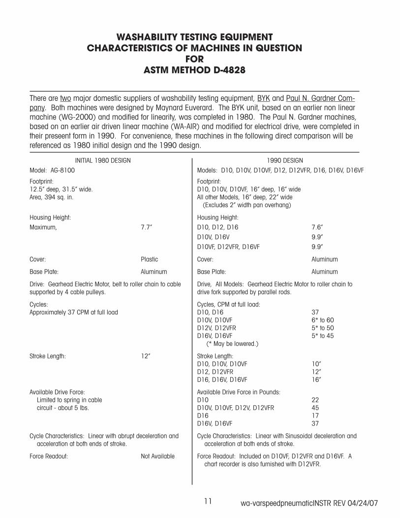
There are two major domestic suppliers of washability testing equipment, BYK and Paul N. Gardner Com-pany. Both machines were designed by Maynard Euverard. The BYK unit, based on an earlier non linear machine (WG-2000) and modified for linearity, was completed in ���0. The Paul N. Gardner machines, based on an earlier air driven linear machine (WA-AIR) and modified for electrical drive, were completed in their preseent form in ���0. For convenience, these machines in the following direct comparison will be referenced as ���0 initial design and the ���0 design.
INITIAL ���0 DESIGN ���0 DESIGN
Model: AG-��00 Models: D�0, D�0V, D�0VF, D�2, D�2VFR, D��, D��V, D��VF
Footprint: Footprint:�2.�” deep, ��.�” wide. D�0, D�0V, D�0VF, ��” deep, ��” wideArea, ��4 sq. in. All other Models, ��” deep, 22” wide (Excludes 2” width pan overhang)
Housing Height: Housing Height:
Maximum, 7.7” D�0, D�2, D�� 7.�”
D�0V, D��V �.�”
D�0VF, D�2VFR, D��VF �.�”
Cover: Plastic Cover: Aluminum
Base Plate: Aluminum Base Plate: Aluminum
Drive: Gearhead Electric Motor, belt to roller chain to cable Drive, All Models: Gearhead Electric Motor to roller chain tosupported by 4 cable pulleys. drive fork supported by parallel rods.
Cycles: Cycles, CPM at full load:Approximately �7 CPM at full load D�0, D�� �7 D�0V, D�0VF �* to �0 D�2V, D�2VFR �* to �0 D��V, D��VF �* to 4� (* May be lowered.)
Stroke Length: �2” Stroke Length: D�0, D�0V, D�0VF �0” D�2, D�2VFR �2” D��, D��V, D��VF ��”
Available Drive Force: Available Drive Force in Pounds: Limited to spring in cable D�0 22 circuit - about � lbs. D�0V, D�0VF, D�2V, D�2VFR 4� D�� �7 D��V, D��VF �7
Cycle Characteristics: Linear with abrupt deceleration and Cycle Characteristics: Linear with Sinusoidal deceleration and acceleration at both ends of stroke. acceleration at both ends of stroke.
Force Readout: Not Available Force Readout: Included on D�0VF, D�2VFR and D��VF. A chart recorder is also furnished with D�2VFR.

wa-varspeedpneumaticINSTR REV 04/24/07�2
INITIAL ���0 DESIGN ���0 DESIGN
Drive Connection to Sponge or Brush Box or Abrasion Boat: Drive Connection to Sponge or Brush Box or Abrasion Boat: Direct cable attachment. These items are cradled in a drive fork, which extends over the test sample, and may be simply lifted free at any time.
Multiple Test Accommodation: Multiple Test Accommodation: Basic design is for driving only one brush box, one sponge The drive fork accepts up to three Brush Boxes or Abrasion box or one abrasion boat. Special attachments may be Boats and two Sponge Boxes. These items may be placed in available for two. any one of three positions.
Adjustment for Sample Thickness: Adjustment for Sample Thickness: No adjustment provided. Drive fork may be adjusted to accommodate test panels up to 2.� inches thick.
Pan Size Accommodation: Pan Size Accommodation: One size 7” x ��” D�0, d�0V, D�0VF �” x ��” All other Models �” x 24”
Pan Edge Available for Clamping of Test Sample: Pan Edge Available for Clamping of Test Sample: Front only. Front and both ends.
Cycle Counter: Cycle Counter: Mechanical with Manual Reset Electro-Mechanical. Counts up to preset value
Test may be conducted directly on Machine support surface: Test may be conducted directly on Machine support surface: Not provided. Accommodated by D�2VFR
•••••••••••••••••••••••••••••••••••••••••• •••••••••••••••••••••••••••••••••••••••••••••••