operating manual - abm-drives.com · fem1.001 rules for the design of hoisting appliances, parts 1,...
TRANSCRIPT

© Copyright ABM Greiffenberger Antriebstechnik GmbH, Friedenfelser Straße 24, 95615 Marktredwitz, 2013
Hoist Drives
Operating manual
for hoist drives
Status : April, 2016
Hoist Drives
Table of contents
1. General safety information ................................................................................................................. 4 1.1. General .................................................................................................................................................. 4 1.2. Explanation of symbols .......................................................................................................................... 4 1.3. Personnel ............................................................................................................................................... 4 1.4. Mechanical hazard ................................................................................................................................. 5 1.5. Thermal hazard ...................................................................................................................................... 5
2. General.................................................................................................................................................. 6 2.1. General instructions ............................................................................................................................... 6 2.2. Used terms ............................................................................................................................................ 6 2.3. Modification of the product..................................................................................................................... 6 2.4. Liability and warranty claims .................................................................................................................. 6 2.5. Addresses .............................................................................................................................................. 7
3. Specification ........................................................................................................................................ 8 3.1. Construction of the hoist drive (schematic diagram) ............................................................................. 8 3.2. Name plate ............................................................................................................................................ 9 3.3. Type designation ................................................................................................................................. 12 3.4. Standards and guidelines .................................................................................................................... 13 3.5. CE conformity ...................................................................................................................................... 14 3.6. Intended use ........................................................................................................................................ 15 3.7. Optional modules ................................................................................................................................. 15
4. Preparation of the drives for operation ........................................................................................... 16 4.1. Motor .................................................................................................................................................... 16 4.2. Brake.................................................................................................................................................... 17
5. Preparation of the drives for operation ........................................................................................... 19 5.1. Shipment and packaging ..................................................................................................................... 19 5.2. Transport and storage ......................................................................................................................... 19 5.3. Mechanical installation ......................................................................................................................... 20 5.4. Electrical installation ............................................................................................................................ 21 5.5. Commissioning .................................................................................................................................... 22 5.6. Commissioning after longer downtimes ............................................................................................... 22
6. Operation ............................................................................................................................................ 23 6.1. Safety instructions ............................................................................................................................... 23 6.2. Error diagnosis and fault removal ........................................................................................................ 24
7. Maintenance ....................................................................................................................................... 27 7.1. Safety instructions ............................................................................................................................... 27 7.2. Maintenance ........................................................................................................................................ 27 7.3. Spare parts .......................................................................................................................................... 30
8. Decommissioning and disposal ....................................................................................................... 31 8.1. Decommissioning ................................................................................................................................ 31 8.2. Recycling and disposal ........................................................................................................................ 32
9. List of images ..................................................................................................................................... 33

Hoist Drives
10. List of tables ....................................................................................................................................... 33
11. Index.................................................................................................................................................... 34
Annex ............................................................................................................................................................. 35
A Spezifikation Hubwerk ...................................................................................................................... 35
B Rectifier............................................................................................................................................... 36 B1 Bridge Rectifier .................................................................................................................................... 36 B2 Fast Excitation Rectifier ....................................................................................................................... 37
C Motor ................................................................................................................................................... 38
D Screw tightening torques.................................................................................................................. 38
E Lubrication ......................................................................................................................................... 39
G Mounting drawings ............................................................................................................................ 40

4
Hoist Drives
1. General safety information
1.1. General
Any work for the transport, storage, installation, commissioning and maintenance may be
carried out with the personal protective equipment required for the work.
1.2. Explanation of symbols
Signal words:
Signal word field with signal word Meaning
DANGER
Indicates a hazard with a high degree of risk
which leads to death or severe injuries if it is not
prevented.
WARNING
Indicates a hazard with a medium degree of risk,
which can lead to death or severe injuries if it is
not prevented.
CAUTION
Indicates a hazard with a low degree of risk which
can cause minor or moderate injuries if it is not
prevented.
Table 1 : Signal words and their meaning
The safety instructions in this operating manual are structured as follows:
Signal word with illustration
HAZARD
Actions to prevent the hazard
1.3. Personnel
Any work for the transport, storage, installation, commissioning and maintenance must only be
carried out by qualified specialist personnel. The binding specifications for the qualification of
electrically qualified persons and electrically skilled personnel apply as defined in DIN VDE
0105-100.

5
Hoist Drives
1.4. Mechanical hazard
Transport, assembly, commissioning and decommissioning, as well as maintenance and
inspection work must only be carried out using the personal protective equipment required for
the respective work, and only by trained specialist personnel while the machine is idle, de-
energised and cooled off.
1.5. Thermal hazard
WARNING
HOT MACHINE PARTS
Hot machine parts can cause burns in case of
skin contact
Do not touch hot surfaces!
If possible, the manufacturer of the complete
machine has to provide suitable touch guards!
Wear the personal protective equipment for
maintenance or troubleshooting work!
Observe the cool-down times!
Electric mains must not be in contact with hot surfaces.
6
Hoist Drives
2. General
2.1. General instructions
Before working with the drive, carefully read the operating manual. This way, you ensure a risk-
free and smooth function of the drive. The instructions of this operating manual must be
observed.
Special designs can deviate in technical details! This operating manual and all associated
special documentations must be kept in close proximity to the drive.
The reproduction, distribution and utilization of this document as well as the communication of
its contents to others without express authorization is prohibited. Offenders will be held liable for
the payment of damages. All rights reserved in the event of the grant of a patent, utility model or
design.
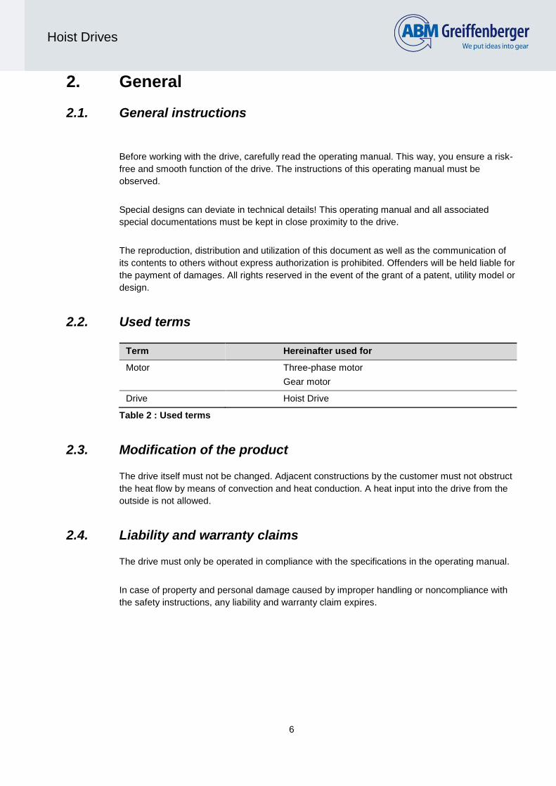
2.2. Used terms
Term Hereinafter used for
Motor Three-phase motor
Gear motor
Drive Hoist Drive
Table 2 : Used terms
2.3. Modification of the product
The drive itself must not be changed. Adjacent constructions by the customer must not obstruct
the heat flow by means of convection and heat conduction. A heat input into the drive from the
outside is not allowed.
2.4. Liability and warranty claims
The drive must only be operated in compliance with the specifications in the operating manual.
In case of property and personal damage caused by improper handling or noncompliance with
the safety instructions, any liability and warranty claim expires.

7
Hoist Drives
2.5. Addresses
Germany
ABM Greiffenberger Antriebstechnik GmbH
Postfach 140 Friedenfelser Str. 24
D - 95614 Marktredwitz D - 95615 Marktredwitz
Phone: +49 9231 67-0
Fax: +49 9231 67-5295
e-mail: [email protected]
USA
ABM DRIVES INC. 2000 Ford Circle, Suite E Milford, Ohio 45150 Phone: +1 513 5761300 Fax: +1 513 5764999 e-mail: [email protected]
Austria
ABM Antriebstechnik GmbH Ortstrasse 18/1/5-7 A - 2331 Vösendorf Phone: +43 1 69911620 Fax: +43 1 699116223 e-mail: [email protected]
France
ABM Systèmes d'Entraiment S.A.R.L. 40, rue Jean Monet Melpark Bat. 5 F - 68200 Mulhouse Phone: +33 3 89334401 Fax: +33 3 89334405 e-mail: [email protected]
P.R. China
ABM Drives (Suzhou) Co., Ltd. Kuachun Industrial Area Unit 9G, Chun Hui Lu, Weiting Town VR China - 215122 Suzhou
Phone: +86 512 - 8717 1081
Fax: +86 512 - 8717 1084
e-mail: [email protected]
Turkey
ABM Greiffenberger Hareket Sistemleri Ticaret Limited Şirketi Barbaros Mah. Bezirgan Sok. No:3
Deluxia Suites A Blok Daire:17 Batı Ataşehir-İstanbul, TR 34746 Phone: +90 216 2903525 Fax: +90 216 2903526 E-Mail: [email protected]
India
ABM Drives India Private Limited Lunkad Sky Vista, 308 Viman Nagar, Near Dorabji Mall, Opp New Airport Road, Pune - 411014
Phone: +91 20 6648 7579
8
Hoist Drives
3. Specification
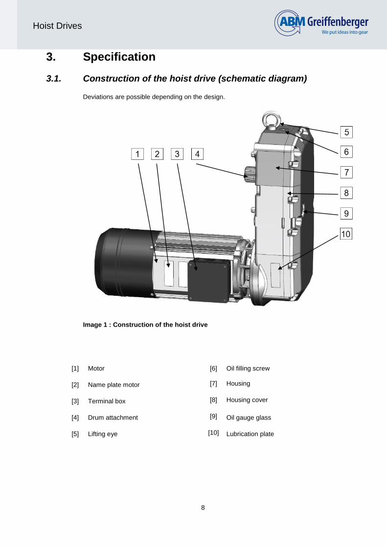
3.1. Construction of the hoist drive (schematic diagram)
Deviations are possible depending on the design.
Image 1 : Construction of the hoist drive
[1] Motor [6] Oil filling screw
[2] Name plate motor [7] Housing
[3] Terminal box [8] Housing cover
[4] Drum attachment [9] Oil gauge glass
[5] Lifting eye [10] Lubrication plate

9
Hoist Drives
3.2. Name plate
Name plate (Example)
Abbreviation Unit Designation
Mot D = three-phase motor
Nr Serial number
TNr ABM part number
IKL Insulation class
UT °C Max. allowed ambient temperature
IP Type of protection (motor/brake) T2 = tropical protection
Type ABM type designation
Operating mode
kW Motor rated power
V Motor connection voltage
Hz Frequency motor voltage
Switching type of the motor (Y / delta)
A Rated current of the motor
Cos-Phi of the motor
1/min Rated speed at the gear shaft // motor shaft
Bra
ke
TS Nm Brake torque
V Brake connection voltage
A Rated current of the brake
CB μF Operating capacitor for single-phase motors
CA μF Starting capacitor for single-phase motors
Table 3 : Field description at the name plate
10
Hoist Drives
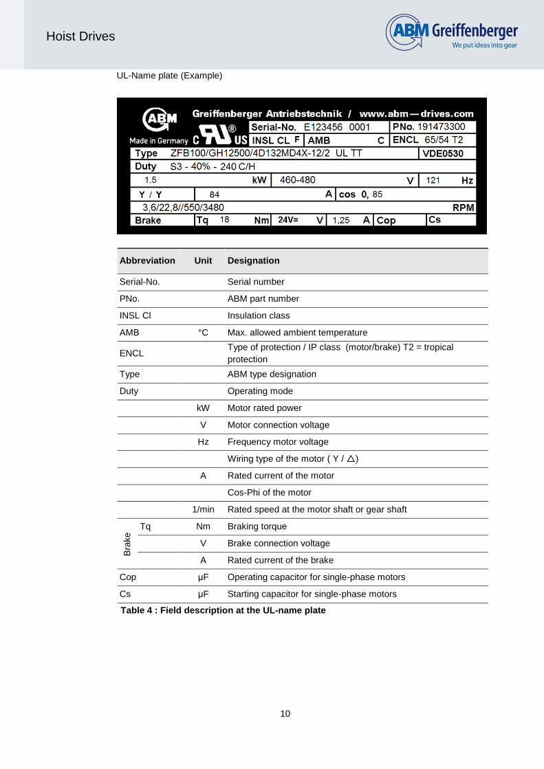
UL-Name plate (Example)
Abbreviation Unit Designation
Serial-No. Serial number
PNo. ABM part number
INSL Cl Insulation class
AMB °C Max. allowed ambient temperature
ENCL Type of protection / IP class (motor/brake) T2 = tropical
protection
Type ABM type designation
Duty Operating mode
kW Motor rated power
V Motor connection voltage
Hz Frequency motor voltage
Wiring type of the motor ( Y / )
A Rated current of the motor
Cos-Phi of the motor
1/min Rated speed at the motor shaft or gear shaft
Bra
ke
Tq Nm Braking torque
V Brake connection voltage
A Rated current of the brake
Cop μF Operating capacitor for single-phase motors
Cs μF Starting capacitor for single-phase motors
Table 4 : Field description at the UL-name plate

11
Hoist Drives
Lubrication plate
Number Designation
1 Date
2 ABM Order Number } ABM Serial Number
3 Consecutive Number
4 Type designation
5 Lubrication type
6 Lubricant volume
7 Ratio
Table 5 : Field description at the name plate

12
Hoist Drives
3.3. Type designation
This documentation applies to ABM drives with the following type designation (example):
ZFB100 / GH12500 / 4D132Md4x-12/2
Brake designation Gear designation Motor designation
Type designation brake
See operating manual brake
Type designation gear
Designation GH = hoist drive
GHX = hoist drive extended version
1. addition Frame size
2. addition Customer specific information (A, S…)
Type designation motor
Casing key
3 = die-cast case
4 = extruded casing
- = bearing plate motor
Motor type D = three-phase motor
1. addition B= reinforced coil
G= non-ventilated
2. addition Motor size (peak height) and packet length
3. addition
Number of poles
Addition „s“: special version
Addition „x“: alloyed rotor
4. addition for 1st addition “G”
FL: forced ventilated
EL: external ventilation
DL: open-circuit ventilated
Table 6 : type designation ABM hoist drives
13
Hoist Drives
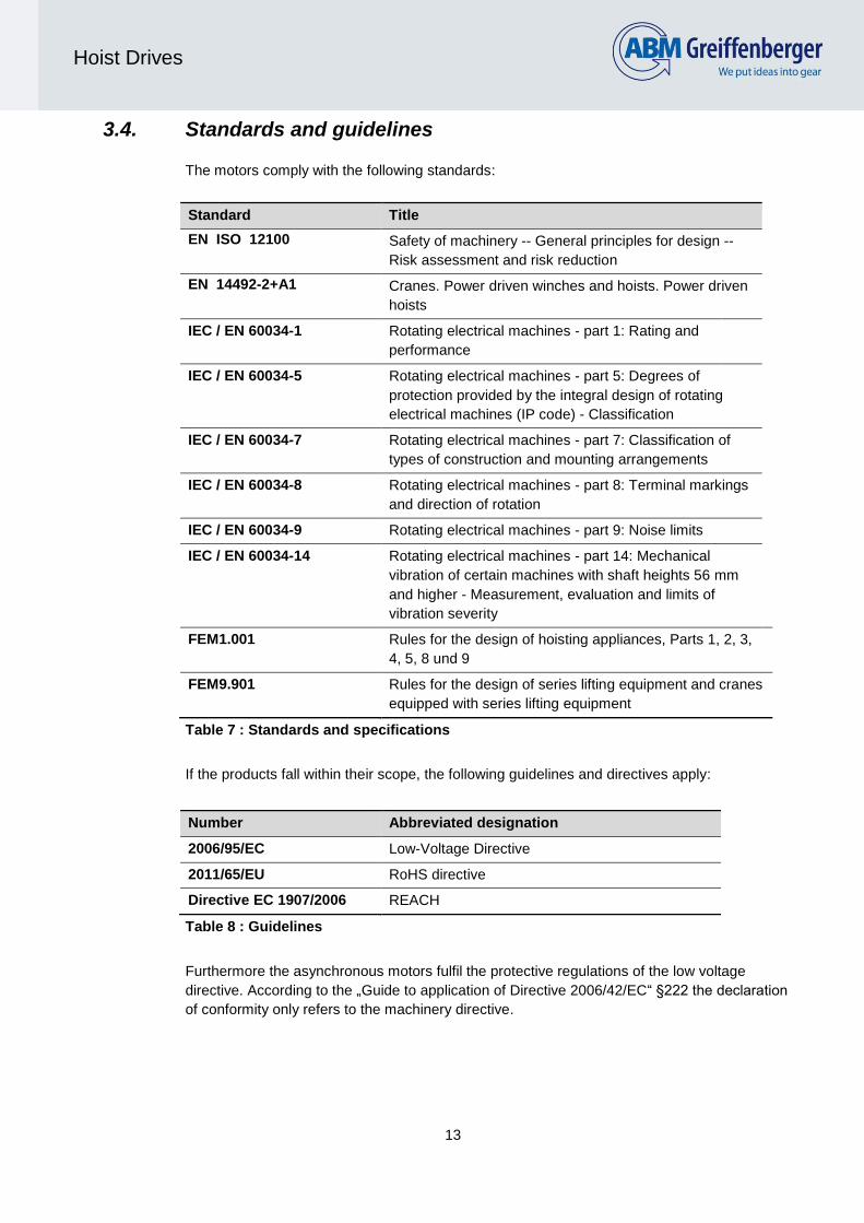
3.4. Standards and guidelines
The motors comply with the following standards:
Standard Title
EN ISO 12100 Safety of machinery -- General principles for design --
Risk assessment and risk reduction
EN 14492-2+A1 Cranes. Power driven winches and hoists. Power driven
hoists
IEC / EN 60034-1 Rotating electrical machines - part 1: Rating and
performance
IEC / EN 60034-5 Rotating electrical machines - part 5: Degrees of
protection provided by the integral design of rotating
electrical machines (IP code) - Classification
IEC / EN 60034-7 Rotating electrical machines - part 7: Classification of
types of construction and mounting arrangements
IEC / EN 60034-8 Rotating electrical machines - part 8: Terminal markings
and direction of rotation
IEC / EN 60034-9 Rotating electrical machines - part 9: Noise limits
IEC / EN 60034-14 Rotating electrical machines - part 14: Mechanical
vibration of certain machines with shaft heights 56 mm
and higher - Measurement, evaluation and limits of
vibration severity
FEM1.001 Rules for the design of hoisting appliances, Parts 1, 2, 3,
4, 5, 8 und 9
FEM9.901 Rules for the design of series lifting equipment and cranes
equipped with series lifting equipment
Table 7 : Standards and specifications
If the products fall within their scope, the following guidelines and directives apply:
Number Abbreviated designation
2006/95/EC Low-Voltage Directive
2011/65/EU RoHS directive
Directive EC 1907/2006 REACH
Table 8 : Guidelines
Furthermore the asynchronous motors fulfil the protective regulations of the low voltage
directive. According to the „Guide to application of Directive 2006/42/EC“ §222 the declaration
of conformity only refers to the machinery directive.

14
Hoist Drives
3.5. CE conformity

15
Hoist Drives
3.6. Intended use
The hoist drives serve as a drive unit for lifting devices.
Ambient conditions Requirement
Ambient temperatures -15° up to +40 °C
Installation height 1000 m above sea level
Humidity Up to 50% (at +40°)
Up to 90% (at room temperature)
Table 9 : Operating conditions according to EN 60034-1 or EN 60204-1
Increased operating conditions, e.g. extended temperature range are according to the data
sheet.
The use in explosive areas is forbidden.
An overload can cause damages to the drive. The maximum load is specified in the data sheet.
In order to prevent an overheating of the drive, it must be ensured that sufficient space is
available for the unobstructed ventilation. The fan cowls must not be covered. When using
several drives in close proximity, it must be ensured that it is possible to prevent a suction of
warm exhaust air.
The technical data on the name plate must be observed. The documentation must be complied
with. For applications in which the failure of a gear or motor could cause a danger to persons,
corresponding safety precautions must be provided.
The motor is no independently functional machine and it is intended for the integration into
another machine. The commissioning is prohibited until it has been determined that the machine
complies with the regulations of the EC directives.
Observe additionally the operating manuals for “electric motor/gear motor” and “brakes”. You
can find these and other manuals after registration in the download area at
http://www.abm-antriebe.de/6009_operating_manuals.html
3.7. Optional modules
Brake with microswitch (for monitoring release or wear)
Brake with manual release
Increased protection class (IP65)
Incremental encoder
External fan

16
Hoist Drives
4. Preparation of the drives for operation
This chapter presents additional informations to the operating manuals for “electric motor/gear
motor” and “brakes”. You can find these and other manuals after registration in the download
area at
http://www.abm-antriebe.de/6009_operating_manuals.html
4.1. Motor
Hoist motor usages must comply with the corresponding mode of operations (see table 15,
annex C). It is imperative to conform to the permitted on times and cycles per hour. Low speed
windings must be activated for at least 1 sec. on all starts and stops.
Minimum and maximum speeds and on times for inverter duty motors are equal to the permitted
mode of operations of two speed motors (12/2 poles).
Example: Hoist Duty Service Classification: FEM 2m
Motor Duty Cycle: S3 – 40 % (based on cycle time of 10 min)
Starts or Stops per Hour: 240 c/h
On Time (ED):
1/3 in low speed winding (approx. 500 RPM) equals 1.3 min.
2/3 in high speed winding (approx. 3000 RPM) equals 2.6 min.
Permitted Starts or Stops per Hours (c/h):
1/3 in high speed winding (approx. 3000 RPM) equals 80 c/h
2/3 in low speed winding (approx. 500 RPM) equals 160 c/h
Thermal Protection
Motor windings can be protected from overheating by PTC-thermistors or thermal sensors.
Single speed motors have 3 PTC-thermistors and 3 thermal sensors, two speed motors have
6 PTC-thermistors and 3 thermal sensors (2 in high-speed winding and 1 in low-speed winding).
ABM motors are designed for insulation class F. When the temperature of the motor exceeds
the rated operating temperature (ROT = 155°C for Iso F) the relay is activated and triggers the
power cut-off. After cooling down below ROT, the low resistance of the PTC-thermistor will allow
the motor (transformer) to be re-started.
Control-relays suitable for use in conjunction with PTC‘s are produced by several
manufacturers.

17
Hoist Drives
4.2. Brake
Rectifiers for two speed motors (12/2- or 8/2pole) are typically connected to the star points of
the winding (tagged 1U2-1V2-1W2 / 2U2-2V2-2W2).
The voltage of the star points will be calculated as follows: (e.g. power supply of 400V):
Most brakes are supplied with 98 V DC or 195 V DC coils depending on rectifier and power
supply voltage. To avoid a long overrun brakes should get switched on DC-side.
Wiring diagrams
Inverter driven motors require a separate
brake supply voltage (B225).
VV
2303
400

18
Hoist Drives
Supply Voltage Coil Voltage
Bridge rectifier Fast-excitation-rectifier
- - 24 V DC
110 - 127V AC 220 - 277V AC 98V DC
130 - 165V AC 278 - 332V AC 136V DC
220 - 277V AC 278 - 500V AC 195V DC
380 - 400V AC - 340V DC
Table 10 : Brake voltages
(green = standard)
Up to motor size 4D112 and brake type ZFB60, the PMBAF 400-S rectifiers are used.
The PMBAF 400-S is a bridge rectifier with a maximum supply voltage of 400V~.
From motor size 4D132 and brake types ZFB100 the PMG500-S rectifier must be used. The
PMG500-S is a fast-excitation-rectifier that switches from bridge rectifying to one-way-rectifying
after 500 ms of operation time with a maximum supply voltage of 500V~.
Thermal sensors and PTC-Thermistors are not connected to the rectifier but to an additional
terminal strip. You can find the technical datas of the rectifiers at annex B
Brakes on two speed motors should not be applied directly from high speed. The hoist
manufacturer is responsible to ensure that the motor is slowed down by the low speed winding
before brakes are applied. Otherwise increased wear of the brake should be expected.
If supplied via rectifier devices, the circuit can be interrupted on AC side or, respectively, on DC
side. The latter switching type results in very short switching times of the brakes. The
disadvantage with this type of switching is the occurrence of high peak voltages (sparking at
switching contacts) which, however, can be prevented by means of protective wiring. In order to
protect the switching contacts against burn-up, we recommend a varistor in parallel to the coil.
The microswitch (optional) monitors release or wear of the brake.

19
Hoist Drives
5. Preparation of the drives for operation
5.1. Shipment and packaging
The drive is delivered with suitable packaging. The outer packaging is taken back.
Incoming control:
- Check the completeness on the basis of the delivery note!
Is the packaging damaged?
- Check the delivery for damages (visual inspection)!
In case of complaints
If the delivery was damaged during transport:
- Contact the forwarding agent immediately!
- Keep the packaging (due to a possible inspection by the forwarding agent, or for the return of
the goods)!
Packaging for the return of the goods
- Pack the motor shockproof.
5.2. Transport and storage
During transport the drives must only be suspended at the provided lifting eyes. Do not attach
additional loads to the motor. Only use suitable lifting means. Improper execution, unsuitable
or damaged devices and tools can cause injuries and/or property damage.
DANGER
FALLING OBJECTS
In case of improper transport, the drive could
detach from the transport and lifting gear.
Falling objects can cause severe injuries.
Staying underneath the drive during transport is
forbidden!
Ensure secure fastening!

20
Hoist Drives
The following points must be observed for the storage:
Storage in installation position, protect the drive against falling
Slightly lubricate blank casing surfaces and shafts
Store in dry, dust-free rooms
Temperature without considerable fluctuations between -25°C and +55°C
Relative humidity less than 60%
No direct sunlight or UV light
No aggressive, corrosive materials (contaminated air, ozone, gases, solvents, acids,
lye, salts, radioactivity etc.) in the surroundings
No shocks and vibrations.
5.3. Mechanical installation
The mechanical connection of the electric motor has to be carried out by a specialist. Only carry
out work at the drive when it is switched off and secured against restart.
Before the installation, check the installation situation. Shearing and crushing points must be
avoided when handling the drive. Fence off the working area. Use the personal protective
equipment.
Product-specific characteristics must be observed when selecting add-on components (fixtures)
and for the later use of the complete machine.
The mounting of drum to output shaft and gearbox must comply with ABM´s mounting drawings
(see annex G). Appropriate materials and surface treatment of the drum and drum flange must
be used to assure a safe gearbox output torque transfer.
The drum respectively the drum flange must be designed to use the load journal behind the
external involute spline to carry loads. The external involute spline is only designed to transmit
the output torque of the gearbox and not to carry any radial forces.

21
Hoist Drives
5.4. Electrical installation
DANGER
ELECTRIC SHOCK
Electrical parts are energized with hazardous
voltage. When touching these parts you will get
an electric shock. Death or severe injuries are
the result.
Any work for electrical installations must only be
carried out by qualified specialists!
Connecting work must only be carried out in de-
energized condition!
Compare the mains voltage and mains frequency with the data on the rating plate. The
allowed mains voltage fluctuation is +10%.
Adjust the cross-sections of the connecting cables to the nominal current pursuant to
the regulations.
Connect and arrange the connection terminals according to the connection plan on the
inside of the terminal box.
Ensure that all connections including ground wire are tightly screwed.
In order to avoid a tensile load of the terminals, mount the connection cables strain-
relieved.
No foreign matters, dirt or humidity may enter the terminal box.
In order to ensure the type of protection when closing the terminal box, use the original
seals.
Close unused cable entries in a dust- and waterproof manner.

22
Hoist Drives
5.5. Commissioning
Before commissioning, ensure that the drive is undamaged and non-choked. Ensure the
proper installation of the safety devices.
In order to check the rotational direction, switch the properly connected motor in
uncoupled condition “On/Off” for a short time.
Connect integrated temperature sensors (PTC thermistor or bimetal temperature
sensor) to the control device. If a continuity test of the temperature sensors is required,
this must be carried out with a measuring bridge (max. 5 V).
During the test run under maximum load, the gear must be checked for:
- Unusual noises such as milling, knocking or grinding noises
- Unusual vibrations, oscillations and movements
- Generation of steam and smoke
The drive must be shut down and ABM must be contacted if an abnormality was
determined during the aforementioned check tests.
After the test run, the gear must be checked for leaks. All fixing bolts have to be
retightened.
5.6. Commissioning after longer downtimes
After longer downtimes (longer than 1 year), check the screw connections and bearings
before the commissioning.
Ensure that cooling airways, especially the openings of the fan cowls, are free from
contaminations
Before commissioning, replace the lubricant in the gear.
Measure the insulation resistance. The maximum discharge current of the coil against
the casing at 1500 V test voltage for the motors in supplied condition is 10 mA. The
measurement must be carried out by a correspondingly qualified employee.

23
Hoist Drives
6. Operation
6.1. Safety instructions
DANGER
MOVING PARTS
Rotating parts can cause injuries
Never reach into moving parts and keep foreign
materials away from these parts!
Safety devices must be provided by the
manufacturer of the complete machine and
must not be removed or put out of operation!
Observe the safety distance!
During operation, motor surfaces must not be touched. The surfaces at the drives can become
very hot. If required, provide a touch guard!
WARNING
HOT MACHINE PARTS
Hot machine parts can cause burns in case of
skin contact
Do not touch hot surfaces!
Observe the cool-down times!
Carry out regular checks during the operation, depending on the operating conditions.
In doing so, pay special attention to:
Unusual or excessive noise or temperature generation,
Loose fixing elements,
The condition of the electric mains,
Stronger vibrations,
Changes in the rotational speed,
Problems with the heat removal due to depositions on the drive system.
In case of faults, contact the maintenance personnel immediately.

24
Hoist Drives
6.2. Error diagnosis and fault removal
DANGER
ELECTRIC SHOCK
Electric parts
Electrical parts are energized with hazardous
voltage. When touching these parts you will get
an electric shock. Death or severe injuries are
the result.
Any repair work must only be carried out by
qualified specialists!
Connecting work must only be carried out in de-
energized condition!
Fault Possible cause Remedy
Motor does not
start
Fuse has blown Replace the fuse
Motor protection does not
switch, error in the control
Check the control of the motor
protection, remove error
Power supply interrupted Check connections, adjust if necessary
Counter torque of the load is
too big
Check load and reduce if necessary
(check application)
Voltage or frequency
deviate severely from the
target value, at least when
switching on
Provide better mains conditions; check
the cross-section of the supply line
Coil defective Repair by manufacturer
Rotor streaks Repair by manufacturer
Drive blocked Check components for free movement;
remove foreign materials from the
motor, if necessary
Blow when
switching on
Gear fixture loose Re-tighten the motor and gear fixture
screws
Wrong rotational
direction
Motor connected incorrectly Interchange the two phases

25
Hoist Drives
Fault Possible cause Remedy
Gearbox drive shaft
does not rotate
although the motor
is rotating
Breakage in the gear Contact ABM-Service
Motor hums and
has a high power
consumption
Coil defective Repair by manufacturer
Rotor streaks Repair by manufacturer
Running noises Foreign materials inside the
motor
Cleaning of the interior, possibly by the
manufacturer
Bearing damage Installation of new grooved ball
bearings, possible repair by
manufacturer
Gearing damage Contact ABM-Service
Oil deficiency Contact ABM-Service
Vibrations Remove cause, balance if necessary
Motor gets too hot Motor switched in delta
instead of Y, as intended
Correct the switching
Overload of the drive Check load and reduce if necessary
Insufficient cooling air,
cooling airways blocked
Ensure free inlet and outlet of the
supply air
Cooling air is preheated Provide fresh air
Ambient temperature too
high
Provide fresh air
Heat removal impaired due
to deposits
Clean the surface of the drives

26
Hoist Drives
Fault Possible cause Remedy
Gear gets too
warm
Unfavourable installation
conditions Contact ABM-Service
Gear damage Contact ABM-Service
Oil escapes from
the gear or motor Seal defective Contact ABM-Service
Oil escapes from
pressure ventilation Incorrect oil level Oil change
Dirty oil Oil change
Table 11 : Error diagnosis

27
Hoist Drives
7. Maintenance
7.1. Safety instructions
DANGER
ELECTRIC SHOCK
Electrical parts are energized with hazardous
voltage. When touching these parts you will get
an electric shock. Death or severe injuries are
the result.
Any maintenance work must only be carried out
by qualified specialists!
Maintenance work must only be carried out if
the system is de-energised and secured against
restart!
WARNING
HOT MACHINE PARTS
Hot machine parts can cause burns in case of
skin contact
Do not touch hot surfaces!
Observe the cool-down times!
7.2. Maintenance
WARNING
FUMES
Chemical cleaning agents can be corrosive or
develop hazardous fumes. Breathing
difficulties, irritation or poisoning can be the
result.
Use the personal protective equipment!
Observe the warning notices of the cleaning
agent producer!

28
Hoist Drives
CAUTION
DUST
When cleaning with compressed air or steam
jet, dirt particles can be raised and inhaled, or
they can reach into the eyes
Use the personal protective equipment!
Ensure proper extraction!
ABM hoists are delivered ready to use. Please note the lubricant informations on the data sheet
(also see annex E).
Shortened maintenance intervals are strongly recommended if gearboxes are exposed to
unfavourable ambient conditions, such as:
High humidity
dusty environment
large ambient temperature fluctuations
The quantity of lubricant is designed for a mounting angle of 0°. Other mounting angles don’t
need other quantities, but in general the quantity of lubricant is adequate when the mid of the oil
gauge glass is reached.
Maintenance
intervals
Maintenance work
Maintenance work for the machine operator:
Regularly Depending on the dirt, clean the motor regularly along the entire
cooling airway.
Maintenance work for specialist personnel:
Every 3000
operating hours, at
least every six
months
Check oil level
Regrease external spline.
Visual check for leakages
Check the coupling
Check the gear for abnormal running noises and / or vibrations
Every 3 years Oil change (for mineral oil)
Every 5 years Oil change (for synthetic oil)
Table 12 : Maintenance work

29
Hoist Drives
Image 2 : Oil change interval for normal operating conditions
We recommend shortened change intervals in case of particularly difficult operating conditions
such as high humidity, aggressive environment, severe temperature fluctuations, etc.
Our gear motors are delivered ready-to-use. The first lubricant filling ex works lasts for approx.
10,000 operating hours for oil filling, for grease filling approx. 8,000 operating hours.
For quantity and type of the lubricant, please see Annex E. In doing so, observe the instructions
in your data sheet. When changing the lubricant, the gear must be cleaned thoroughly.
DANGER
HOT OIL
In case of contact with hot oil, there is a risk of
scalding
Open the discharge carefully!
Wear the personal protective equipment!
Ensure that no dirt reaches the inside of the gear when changing the lubricant. Remove
bypassing oil immediately using an oil binding agent.
Opera
ting h
ours
Oil bath - continuous temperature

30
Hoist Drives
7.3. Spare parts
We expressly point out that spare and equipment parts, which were not delivered by ABM, were also not tested and approved by ABM.
The installation and / or use of such products could therefore have a negative impact on the constructive properties of your drive. The liability of the manufacturer is excluded for damages arising from the use of non-original spare parts and non-original equipment.
Request a separate spare parts drawing and list for your drive.

31
Hoist Drives
8. Decommissioning and disposal
8.1. Decommissioning
First, remove the electrical connections
DANGER
ELECTRIC SHOCK
Electrical parts are energized with hazardous
voltage. When touching these parts you will get
an electric shock. Death or severe injuries are
the result.
Any electrical work for the decommissioning
must only be carried out by qualified specialists!
Electrical work must only be carried out if the
system is de-energised and secured against
restart!
Remove the lubricant
Remove the drive from the machine
Transport the drive to the work station prepared for the disassembly. Observe the
instruction in the chapter “Transport”
Protect the drive and the components against falling when disassembling
DANGER
FALLING OBJECTS
Falling objects can cause severe injuries.
Ensure secure fastening!

32
Hoist Drives
8.2. Recycling and disposal
Divide the components into the following category for recycling:
Electronic scrap
Iron scrap
Aluminium
Non-ferrous metal such as motor coil
Insulation material, cables
Divide the auxiliary materials into the following category for recycling:
Oil
Grease
Anticorrosive agents
Dispose of the components in compliance with the national and local regulations.

33
Hoist Drives
9. List of images
Image 1 : Construction of the hoist drive ............................................................................................................ 8
Image 2 : Oil change interval for normal operating conditions ......................................................................... 29
10. List of tables
Table 1 : Signal words and their meaning .......................................................................................................... 4
Table 2 : Used terms .......................................................................................................................................... 6
Table 3 : Field description at the name plate ..................................................................................................... 9
Table 4 : Field description at the UL-name plate.............................................................................................. 10
Table 5 : Field description at the name plate ................................................................................................... 11
Table 6 : type designation ABM hoist drives .................................................................................................... 12
Table 7 : Standards and specifications ............................................................................................................ 13
Table 8 : Guidelines .......................................................................................................................................... 13
Table 9 : Operating conditions according to EN 60034-1 or EN 60204-1 ........................................................ 15
Table 10 : Brake voltages ................................................................................................................................. 18
Table 11 : Error diagnosis ................................................................................................................................ 26
Table 12 : Maintenance work ........................................................................................................................... 28
Table 13 : Technical data of bridge rectifier PMBAF 400-S ............................................................................. 36
Table 14 : Technical data of fast excitation rectifier PMG 500-S ..................................................................... 37
Table 15 : Relationship between cyclic duration factor, number of cycles and starts/hour ............................. 38
Table 16 : Screw tightening torques in Nm ...................................................................................................... 38
Table 17 : Lubricant amounts hoist drives ........................................................................................................ 39
Table 18 : Lubricant table ................................................................................................................................. 39

34
Hoist Drives
11. Index
A
Adresses ................................................................................ 7
B
Brake ................................................................................... 17
C
Commissioning .................................................................... 22
Conformity .......................................................................... 14
Construction .......................................................................... 8
D
Decommissioning ................................................................ 31
Disposal ............................................................................... 32
E
Error .................................................................................... 24
F
Fault removal ...................................................................... 24
G
Guidelines............................................................................ 13
I
Installation..................................................................... 20, 21
Insulation resistance ........................................................... 22
Intended use ....................................................................... 15
L
Lubricant change ................................................................. 29
Lubrication .......................................................................... 39
M
Maintenance ....................................................................... 27
Modification .......................................................................... 6
Motor ............................................................................. 16, 38
Mounting ............................................................................. 40
N
Name plate ................................................................ 9, 10, 11
O
Oil change ............................................................................ 29
Operation............................................................................. 23
Optional modules ................................................................ 15
P
Packaging ............................................................................. 19
R
Rectifier ............................................................................... 36
Recycling .............................................................................. 32
S
Safety ..................................................................................... 4
Signal words ........................................................................... 4
Spare parts ........................................................................... 30
Specification ........................................................................ 35
Standards ............................................................................. 13
Storage................................................................................. 20
Surface ....................................................................... 5, 23, 27
T
Terms ..................................................................................... 6
Thermal Protection .............................................................. 16
Transport ............................................................................. 19
Type designation.................................................................. 12
W
Warranty .......................................................................... 6, 30
Wiring diagrams ................................................................... 17

35
Hoist Drives
Annex
A Specification Hoist
Shall the drive be used Indoor Outdoor
Enclosure (IP)
Hoisting load (kg)
Hoisting velocity
(1 or 2 speed)
(m/min)
Drum diameter (mm)
Efficiency (Rope/Rope drum) (%)
Rated power (kW)
FEM Rating
Duty cycle % CDF
Start/stops per hour c/h
Operating voltage (V)
Frequency (Hz)
Brake voltage (V)
Brake torque (Nm)
Other specification
Reeving

36
Hoist Drives
B Rectifier
B1 Bridge Rectifier
Technical data of bridge rectifier PMBAF 400-S
Type Bridge rectifier
Rated voltage max. 400 V ± 10% 50 / 60 Hz AC
Operating voltage max. 360 V DC
Output current max. 2,0 A DC (Tamb= 45°C)
Table 13 : Technical data of bridge rectifier PMBAF 400-S

37
Hoist Drives
B2 Fast Excitation Rectifier
Technical data of fast excitation rectifier PMG 500-S
Type Schnellerregungsgleichrichter
Rated voltage 215 - 500 V ± 10% 50 / 60Hz AC
Output voltage 194 - 450 V = (500 ms)
97 - 225 V = (cont.)
Admissible ambient temperature -25°C bis +80°C
Max. output current (Tamb=45°C) 4,0 A = (500 ms) / 2,0 A = (cont.)
Min. output current 0,02 A = (500 ms) / 0,01 A = (cont.)
Max. switching power 210 W (600 c/h)
Over excitation time 500 ms ± 200 ms
Recovery time app. 150 ms
Table 14 : Technical data of fast excitation rectifier PMG 500-S

38
Hoist Drives
C Motor
Minimum values for the number of starts per hour, and also relationship for the minimum values
between cyclic duration factor, number of cycles per hour and starts per hour given in table 15
Group of mechanisms
Intermittend duty Short time duty
Cycles/h No. of
starts / h CDF in %
Operating time in min.
high speed low-speed
1 Dm M 1 15 90 15 7,5 1,5
1 Cm M 2 20 120 20 7,5 2
1 Bm M 3 25 150 25 15 2,5
1 Am M 4 30 180 30 15 3
2 m M 5 40 240 40 30 3,5
3 m M 6 50 300 50 30 4
4 m M 7 60 360 60 60 5
5 m M 8 60 360 60 > 60 6
Table 15 : Relationship between cyclic duration factor, number of cycles and starts/hour
D Screw tightening torques
Thread Strength class of screw connection
Terminal board / steel nuts
Terminal board / brass nuts
8.8 10.9 12.9
M4 3,2 5 6 1,5 1,5
M5 6,4 9 11 2,4 3
M6 11 16 19 3,75 5
M8 27 39 46 7,5 10
M10 53 78 91
M12 92 135 155
M16 230 335 390
M20 460 660 770
M24 790 1150 1300
Tolerance of all tightening torques = 15%
Delivery status for teminal boards: upper nut tightened with reduced moment
Table 16 : Screw tightening torques in Nm
39
Hoist Drives
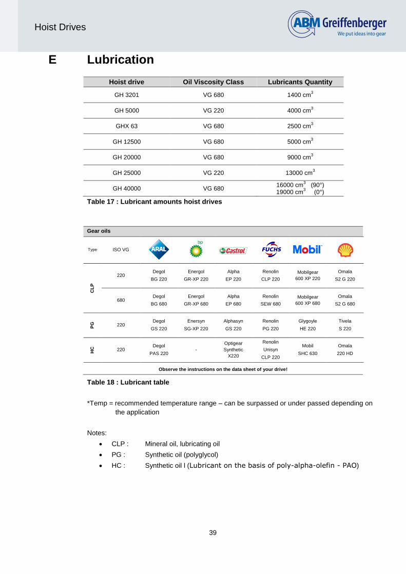
E Lubrication
Hoist drive Oil Viscosity Class Lubricants Quantity
GH 3201 VG 680 1400 cm3
GH 5000 VG 220 4000 cm3
GHX 63 VG 680 2500 cm3
GH 12500 VG 680 5000 cm3
GH 20000 VG 680 9000 cm3
GH 25000 VG 220 13000 cm3
GH 40000 VG 680 16000 cm
3 (90°)
19000 cm3 (0°)
Table 17 : Lubricant amounts hoist drives
Gear oils
Type ISO VG
CL
P
220
Degol
BG 220
Energol
GR-XP 220
Alpha
EP 220
Renolin
CLP 220
Mobilgear
600 XP 220
Omala
S2 G 220
680
Degol
BG 680
Energol
GR-XP 680
Alpha
EP 680
Renolin
SEW 680
Mobilgear
600 XP 680
Omala
S2 G 680
PG
220
Degol
GS 220
Enersyn
SG-XP 220
Alphasyn
GS 220
Renolin
PG 220
Glygoyle
HE 220
Tivela
S 220
HC
220
Degol
PAS 220 -
Optigear
Synthetic
X220
Renolin
Unisyn
CLP 220
Mobil
SHC 630
Omala
220 HD
Observe the instructions on the data sheet of your drive!
Table 18 : Lubricant table
*Temp = recommended temperature range – can be surpassed or under passed depending on
the application
Notes:
CLP : Mineral oil, lubricating oil
PG : Synthetic oil (polyglycol)
HC : Synthetic oil l (Lubricant on the basis of poly-alpha-olefin - PAO)

40
Hoist Drives
G Mounting drawings

41
Hoist Drives

42
Hoist Drives

43
Hoist Drives

44
Hoist Drives

45
Hoist Drives

46
Hoist Drives