operating manual - dynisco · -1- dynisco 1490 1/8 din indicator concise product manual 59476-9...
TRANSCRIPT

From lab to production, providing a window into the process
-1-www.dynisco.com
Rev: n/aP/N: n/a ECO: n/a
Dynisco 1490 1/8 DIN Indicator Concise Product Manual 59476-9
Operating Manual

From lab to production, providing a window into the process
-2-www.dynisco.com
Rev: n/aP/N: n/a ECO: n/a
CAUTION: Installation should be only performed by technically competent personnel. Local Regulations regarding electrical installation & safety must be observed. The host equipment is required to provide a suitable electrical, mechanical and fire enclosure to meet relevant safety standards. Impairment of protection will occur if the product is used in a manner not specified by the manufacturer.
CAUTION: All power supply connections to the device must be removedwhen carrying out any form of maintenance.
1. InstallationInstalling Option Modules/Maintenance
CPU PCB
Future Option
Option Module 2
Option Module 1
Mounting Sturts
Option Module A
Option Module 3
PSU PCB
To access modules, first detach the PSU and CPU boards from the front by lifting firstthe upper, and then lower mounting struts. Gently separate the boards.
a. Plug the required option modules into the correct connectors, as shown below.b. Locate the module tongues in the corresponding slot on the opposite board.c. Hold the main boards together while relocating back on the mounting struts.d. Replace the instrument by aligning the CPU and PSU boards with their guides in the housing, then slowly push the instrument back into position.
NOTE: Option modules are automatically detected at power up.

From lab to production, providing a window into the process
-3-www.dynisco.com
Rev: n/aP/N: n/a ECO: n/a
Option Module Connectors
Panel-MountingThe mounting panel must be rigid, andmay be up to 6.0mm (0.25inch) thick.Cut-out sizes are:
Cut-Out Dim A = 92mm Cut-Out Dim B = 45mm
For n multiple instruments mountedside-by-side, cut-out A is 96n-4mm
Tolerance +0.5, -0.0mm

From lab to production, providing a window into the process
-4-www.dynisco.com
Rev: n/aP/N: n/a ECO: n/a
Mounting Panel
InstrumentHousing
Ratchets
Gasket
1. Insert instrument intothe panel cut-out.
2. Hold front bezelfirmly (withoutpressing on displayarea), and re-fitmounting clamp.
3. Push clamp forward,using a tool ifnecessary, untilgasket iscompressedand instrument heldfirmly in position.
NOTE: For an effective IP66 seal against dust and moisture, ensuregasket is well compressed against the panel, with the 4 tongues locatedin the same ratchet slot.
Rear Terminal Wiring
All connections to the device must be made through a spade format or similar connection, with connection to the spade terminal touching both the insulation and conductor material. (Use a standard crimping tool). Connections must be mechanically secured so as to prevent any wiring becoming loose and coming in contact with other wires or the instrument casing.
The above applies to any and all connection to hazardous mains supply, either direct or indirect (e.g. via a switch or relay).
USE COPPER CONDUCTORS (EXCEPT FOR T/C INPUT) Use Screened Cable on Retransmission Option 1Single Strand wire gauge: Max 1.2mm (18SWG)

From lab to production, providing a window into the process
-5-www.dynisco.com
Rev: n/aP/N: n/a ECO: n/a
Connections
This diagram shows all possible option combinations. The actual connectionsrequired depend on the options fitted.
CAUTION: Check information label on housing for correct operating voltage before connecting supply to Power InputFuse: 90 – 264V ac – 1Amp anti-surge 24/48V ac/dc – 315mA anti-surge
Electrical shock can result in death or serious injury. Avoid contact with the leads and terminals. High voltages that may be present on leads can cause electrical shock.
Note: At first power-up, or upon hardware change, the message Goto isdisplayed for 1 second then ConF is displayed. You must go into theconfiguration mode as described in section 3 of this manual. Access to othermenus is denied until Configuration Mode is completed.

From lab to production, providing a window into the process
-6-www.dynisco.com
Rev: n/aP/N: n/a ECO: n/a
2. Select Mode
3. Configuration Mode
Select mode is used to access the configuration and operation menu functions. It can be accessed at any time by holding down and pressing . The SELCt legend is shown for 1 second, followed by the legend for the current mode. Press or to choose the required mode, then press to enter. An unlock code is required to prevent unauthorised entry to Configuration, & Setup modes. Press or to enter the unlock code, then press to proceed.
NOTE: Automatic return to Operator Mode after 2 minutes without key activity.
First select Configuration mode from Select mode (refer to section 2). Press to scroll through the parameters. While this key is pressed, and up to 1 second after, the parameter legend is shown, followed by the current value. Press or to set the required value. Press to display YES? , press accept the change, otherwise parameter will revert to previous value. To exit fromConfiguration mode, hold down and press , to return to Select mode.
Note: Parameters displayed depend on how instrument has been configured. Refer to user guide (available from your supplier) for further details. Parameters marked * are repeated in Setup Mode.

From lab to production, providing a window into the process
-7-www.dynisco.com
Rev: n/aP/N: n/a ECO: n/a

From lab to production, providing a window into the process
-8-www.dynisco.com
Rev: n/aP/N: n/a ECO: n/a

From lab to production, providing a window into the process
-9-www.dynisco.com
Rev: n/aP/N: n/a ECO: n/a

From lab to production, providing a window into the process
-10-www.dynisco.com
Rev: n/aP/N: n/a ECO: n/a
4. Setup ModeNote: Configuration must be completed before adjusting Setup parameters.First select Setup mode from Select mode (refer to section 2). Press to scroll through the parameters (while this key is pressed, and for 1 sec after, the parameter legend is shown, then the current value). Press or to change the value. To exit from Setup mode, hold down and press to return to Select mode.Note: Parameters displayed depends on how instrument has been configured.

From lab to production, providing a window into the process
-11-www.dynisco.com
Rev: n/aP/N: n/a ECO: n/a
Note: Operator mode screens follow, without exiting from Setup mode.
5. Strain Gauge Calibration Mode
Note: Configuration must be completed before adjusting Calibration parameters.
First select Calibration mode from Select mode (refer to section 2). Press to scroll through the parameters (while this key is pressed, and for 1 sec after, the parameter legend is shown, then the current value). Press or to change the value. To exit from Calibration mode, hold down and press to return to Select mode.Note: Calibration mode will only be displayed if input type is set to Str_G

From lab to production, providing a window into the process
-12-www.dynisco.com
Rev: n/aP/N: n/a ECO: n/a
When the calibration procedure begins ---- appears on the screen. Once the calibration is complete donE appears on the screen.
If there are faults detected with the calibration the error message ErCAL willappear.
ErCAL appears during the low calibration step if the offset is greater than -10mV, for example -11mV. This could signify a faulty sensor.
ErCAL appears during the high calibration step if the count value is greater than +50mV. Again this could signify a faulty sensor.
Note: Performing a calibration with less than a 10mV difference between the high and low calibration values will compromise the accuracy of the instrument.
6. Special Mode
7. Messages & Error Indications
Note: Configuration must be completed before adjusting Special parameters.
This mode enables special features with the correct code entered; enter a value of 0 as default otherwise please refer to your supplier for information on what special features are available and which numbers invoke these.
These messages indicate that the instrument may require attention, or there is a problem with the signal input connection. The message legend is shown for 1 second, followed by its value.Caution: Do not continue with the process until the issue is resolved.

From lab to production, providing a window into the process
-13-www.dynisco.com
Rev: n/aP/N: n/a ECO: n/a
Note: CHH], CLL] or OPEN may also be displayed if an incorrect input type is selected.
8. Operator ModeThis mode is entered at power on, or accessed from Select mode (see section 2).
Note: All Configuration mode and Setup mode parameters must be set as required before starting normal operations.
Press to scroll through the parameters (while this key is pressed, and for 1 sec after, the parameter legend is shown, followed by the current value).
Note: All Operator Mode parameters in Display strategy 6 are read only (see diSP in configuration mode), they can only be adjusted via Setup mode.

From lab to production, providing a window into the process
-14-www.dynisco.com
Rev: n/aP/N: n/a ECO: n/a

From lab to production, providing a window into the process
-15-www.dynisco.com
Rev: n/aP/N: n/a ECO: n/a
Alarm Indication The Active Alarm Status screen indicates any active alarms. In addition, the associated Alarm LED flashes. For latching alarm outputs, the LED flashes when the alarm condition exists,and goes to ON when the alarm condition is no longer present if the output has not yetbeen reset.*Resetting Latched Alarm OutputsAny latched outputs can be reset whilst the Process variable or Alarm Status screensare displayed, by pressing the or key, via the Digital Input or with acommunications command via the RS485 module (if fitted).Note: Outputs will only reset if their alarm condition is no longer present.
Multi-Point ScalingWhen enabled (Mm PS =EnAb), up to 9 breakpoints canbe set to compensate for nonlinearinput signals.For each breakpoint, the inputscale value (ScALn) is entered in % of input span, followed by the value to be shown (diSPn) in displayunits.Each breakpoint’s input scale value must be higher than the previous value, but the display values can be higher or lower. Any scale value set to 100% becomes the last in the series.
Tare FeatureWhen Tare is enabled (TARE = ENAB), it can be used to set the displayed value to zero automatically, by making the PV Offset parameter equal, but opposite to, the current process variable value. Tare can be initiated via the Digital Input (if fitted), with a communications command via the RS485 module (if fitted) or by using the following key press sequence:Press until the process variable is displayed.Hold down and together for three seconds until the display shows YES?Release both keys and press within 3 seconds to confirm the request.The display should read 0 briefly, then begin responding to input signal changes. This will have no effect on any stored Max or Min values until they are reset. Once Reset the Max and Min value will follow the displayed value that has gone through the tare processNote: Tare request is aborted if this sequence is not followed exactly.

From lab to production, providing a window into the process
-16-www.dynisco.com
Rev: n/aP/N: n/a ECO: n/a
9. Product Information ModeFirst select Product information mode from Select mode (refer to section 2). Press to view each parameter (while this key is pressed, and for 1 sec after, the parameter legend is shown, followed by its value). Hold down and press to return to Select mode. Note: These parameters are all read only.
10. Serial CommunicationsRefer to the full user guide (available from your supplier) for details.

From lab to production, providing a window into the process
-17-www.dynisco.com
Rev: n/aP/N: n/a ECO: n/a
11. SpecificationsUNIVERSAL INPUTStrain Gauge: 350Ω, by means of 4 or 6 wire (6 to use internal Shunt resistor) Bridge excitation: 10Vdc ± 7% Bridge Sensitivity: 1.4-4mV/V Shunt Value: From 40%to 100% Input signal Span: -25% to 125% (Approx. -10mV to +50mV)ThermocoupleCalibration: ±0.1% of full range, ±1LSD (±1°C for Thermocouple CJC). BS4937, NBS125 & IEC584.PT100 Calibration: ±0.1% of full range, ±1LSD.B S1904 & DIN43760 (0.00385 / /°C).DC Calibration: ±0.1% of full range, ±1LSD.Sampling Rate: 10 per second, 16 bit resolution approximately (100ms sample time)Impedance: >10M resistive, except dc mA (5 ) and V (47k ).
Strain Gauge: Depending on user setting InPF can cause input to fail high scale or low scale reading. Reading will fail on either, Sig+ or Sig- loss, or incorrect excitation output <0.8mA and >50mA supply.Thermocouple/RTD: High alarms activate for sensor break. Linear 4 to 20mA, 2 to 10V and 1 to 5V DC: Low alarms activate for sensor break.Note: Sensor break not detectable on 0 to 20mA, 0 to 50mV, 0 to 5V & 0 to 10v input types.Isolated from all outputs. Universal input must not be connectedto operator accessible circuits if single relay outputs areconnected to a hazardous voltage source. Supplementaryinsulation or input grounding would then be required
Sensor BreakDetection:
Isolation:
Logic Input
Input Signal: If the Logic State setting in Config Mode = CLS, Reset or Tare occurs on an Open to Closed transition, or high (3 to 5VDC) to low (<0.8VDC) transition. If Logic State setting in Config Mode = OPN, Reset or Tare occurs on a Closed to Open transition, or low (<0.8VDC) to high (3 to 5VDC)) transition.
Isolation: No isolation from inputs and other outputs.

From lab to production, providing a window into the process
-18-www.dynisco.com
Rev: n/aP/N: n/a ECO: n/a
OUTPUTSSingle RelayContact Type &Rating: Single pole double throw (SPDT), latching or non-latching action (selectable); 2A resistive at 120/240VAC.Lifetime: >500,000 operations at rated voltage/current.Isolation: Basic Isolation from universal input and SSR outputs.
Dual RelayContact Type &Rating: Single pole single throw (SPST), latching or non-latching action (selectable); 2A resistive at 120/240VAC.Lifetime: >200,000 operations at rated voltage/current.Isolation: Reinforced safety isolation from inputs and other outputs.
Linear DCAccuracy: ±0.1% of span (mA @ 250Ω, V @ 2kΩ).Resolution: 15 3/4 bit (1 part in 52K) and updated at approx. 65ms intervals. (130ms settling time)Isolation: Reinforced safety isolation from inputs and other outputs.
Transmitter PSUPower Rating: 24V Tx PSU Module; Unregulated 18 to 32V DC into 400 Ω min Linear Output Module; Regulated 0.0 to 10.0V into 500 Ω min.Isolation: Reinforced safety isolation from inputs and other outputs.SERIAL COMMUNICATIONS (RS485) (option)Physical: 1200, 2400, 4800, 9600 or 19200 bps.Protocols: Selectable between Modbus and West ASCII.Isolation: Reinforced safety isolation from all inputs and outputs.
OPERATING CONDITIONS (FOR INDOOR USE)Ambient Temperature: 0°C to 55°C (Operating), –20°C to 80°C (Storage).Relative Humidity: 20% to 95% non-condensing.Altitude <2000mSupply Voltage andPower: 100 to 240VAC 10%, 50/60Hz, 9VA (for mains powered versions), or 20 to 48VAC 50/60Hz 9VA or 22 to 65VDC 5W (for low voltage versions).
From lab to production, providing a window into the process
-19-www.dynisco.com
Rev: n/aP/N: n/a ECO: n/a
ENVIRONMENTALStandards: CE & ULEMI: EN61326-1:2013, Table 2 & Class A.Warning: This is a Class A product. In a domestic environment this product may cause radiointerference in which case the user may be required to take adequate measures.SafetyConsiderations: UL61010-1 Edition 3, Pollution Degree 2 & Installation Category II.Front Panel Sealing: IP66 (IP20 behind the panel).(IP rating tested by a UKAS accredited laboratory, but not recognized by UL).
PHYSICALFront Bezel Size: 96 x 48mm (1/8 Din Horizontal).Depth Behind Panel: 100mm.Weight: 0.21kg maximum.
MANUFACTURING SITEAddress: The Hyde Business Park, Brighton, BN2 4JU, United Kingdom
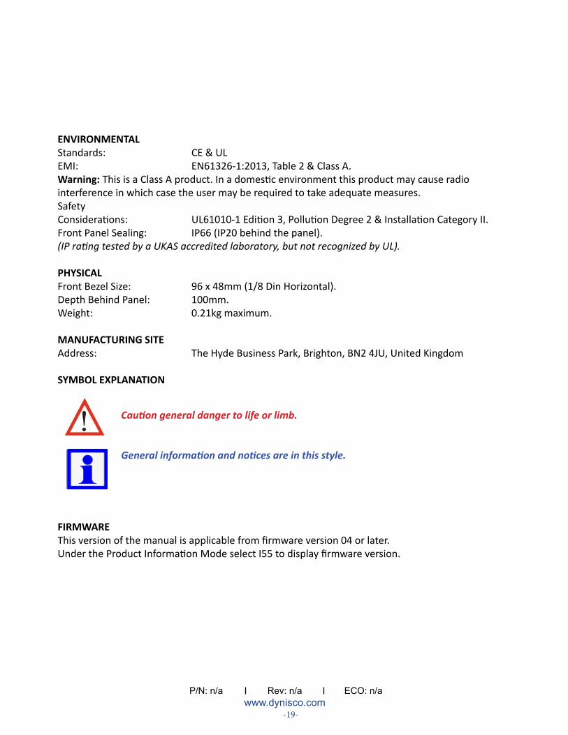
SYMBOL EXPLANATION
FIRMWAREThis version of the manual is applicable from firmware version 04 or later.Under the Product Information Mode select I55 to display firmware version.
Caution general danger to life or limb.
General information and notices are in this style.