operating manual - nurdspace · if you are not able to solve a problem using this manual, ......
TRANSCRIPT

OPTIMUMM A S C H I N E N - G E R M A N Y
4.1.12 L
© 2
012
GB
Lathe
OPTI D180 x 300 VARIO
Version 1.3.7
Keep for future reference!
Operating manual
Page 1athe OPTI D180 x 300 VARIO Version 1.3.7 Translation of the original instructions

OPTIMUMM A S C H I N E N - G E R M A N Y
Table of Contents
Page 2
© 2012
G
1 Safety ................................................................................................................................ 51.1 Safety warnings (warning notes) ............................................................................................ 6
1.1.1 Classification of hazards ...................................................................................... 61.1.2 Further ideograms ................................................................................................ 7
1.2 Proper use ............................................................................................................................. 71.3 Reasonably foreseeable misuse ............................................................................................ 8
1.3.1 Avoiding misuse ................................................................................................... 81.4 Possible dangers caused by the lathe ................................................................................... 81.5 Qualification of personnel ....................................................................................................... 9
1.5.1 Target group ........................................................................................................ 91.5.2 Authorised personnel ......................................................................................... 101.5.3 Obligations of the operator ................................................................................. 101.5.4 Obligations of the user ....................................................................................... 101.5.5 Additional qualification requirements ................................................................. 10
1.6 User positions ...................................................................................................................... 101.7 Safety measures during operation ...................................................................................... 111.8 Safety devices ...................................................................................................................... 111.9 EMERGENCY-STOP ........................................................................................................... 12
1.9.1 Main switch ........................................................................................................ 121.9.2 Protective cover with safety switch .................................................................... 121.9.3 Lathe chuck protection with position switch ....................................................... 121.9.4 Lathe chuck key ................................................................................................. 13
1.10 Safety check ........................................................................................................................ 131.11 Individual protection gear ..................................................................................................... 141.12 Safety during operation ........................................................................................................ 141.13 Disconnecting the lathe and making it safe .......................................................................... 151.14 Using lifting equipment ......................................................................................................... 151.15 Mechanical maintenance work ............................................................................................. 15
2 Technical data .................................................................................................................. 162.1 Power connection ................................................................................................................. 162.2 Machine data ....................................................................................................................... 162.3 Dimensions .......................................................................................................................... 162.4 Operating material ................................................................................................................ 162.5 Environmental conditions ..................................................................................................... 162.6 Emissions ............................................................................................................................ 172.7 Dimensions, installation plan D180x300 Vario .................................................................... 18
3 Assembly ......................................................................................................................... 193.1 Extent of supply ................................................................................................................... 193.2 Transport .............................................................................................................................. 193.3 Storage ............................................................................................................................... 203.4 Installation and assembly .................................................................................................... 21
3.4.1 Requirements of the installation site .................................................................. 213.4.2 Load suspension point ....................................................................................... 213.4.3 Installation .......................................................................................................... 21
3.5 First use ............................................................................................................................... 223.5.1 Warming up the machine ................................................................................... 223.5.2 Cleaning and greasing ....................................................................................... 223.5.3 Optional accessory ............................................................................................ 23
4 Operation ......................................................................................................................... 254.1 Safety ................................................................................................................................... 254.2 Control and indicating elements ........................................................................................... 25
4.2.1 Switching elements ............................................................................................ 264.2.2 Switching on the machine .................................................................................. 264.2.3 Switching off the machine .................................................................................. 274.2.4 Clamping the tooln ............................................................................................. 27
4.3 Clamping a workpiece into the lathe chuck .......................................................................... 284.3.1 Replacing the clamping jaws on the lathe chuck ............................................... 294.3.2 Head spindle seat .............................................................................................. 29
4.1.12Translation of the original instructions Lathe OPTI D180 x 300 VARIO Version 1.3.7
B

OPTIMUMM A S C H I N E N - G E R M A N Y
4.1.12 L
© 2
012
GB
4.3.3 Mounting of follow rest ....................................................................................... 314.3.4 Mounting of steady rest ...................................................................................... 314.3.5 Use of collet chucks ........................................................................................... 32
4.4 Switching ON / OFF ............................................................................................................. 324.4.1 Change-over switch ............................................................................................ 32
4.5 Adjusting the speed .............................................................................................................. 334.5.1 Changing the speed range ................................................................................. 33
4.6 Turning between centers ..................................................................................................... 344.7 Adjusting feeds and thread pitches ...................................................................................... 34
4.7.1 Switching on the feed ......................................................................................... 354.8 General working notes ......................................................................................................... 36
4.8.1 Coolant ............................................................................................................... 365 Appendix turning ............................................................................................................. 37
5.1 ISO-designation system for tool holder, inside machining .................................................. 385.2 ISO-designation system for tool holder, outside machining .............................................. 395.3 Cutter with hard metal reversible carbide tip soldered on ................................................... 405.4 Cut the first chips .................................................................................................................. 405.5 Outside machining, longitudinal turning and facing ............................................................. 425.6 Inside machining, drilling and longitudinal turning ................................................................ 425.7 Tapping of external and internal threads .............................................................................. 43
5.7.1 Thread types ...................................................................................................... 445.7.2 Metric thread (60° flank angle) ........................................................................... 475.7.3 British threads (55° flank angle) ......................................................................... 495.7.4 Indexable inserts ................................................................................................ 505.7.5 Examples for thread cutting ................................................................................ 52
5.8 Recessing, cutting off and turning off ................................................................................... 545.9 Turning cones with high precision ....................................................................................... 565.10 Cutting material ................................................................................................................... 59
5.10.1 Cutting materials for chipping ............................................................................. 595.11 Standard values for cutting data when turning ..................................................................... 60
5.11.1 Cutting speed table ............................................................................................ 615.12 Grinding or regrinding of cutting edge geometries of turning tools ....................................... 61
5.12.1 Terms for the turning tool ................................................................................... 625.12.2 Cutting edge geometry for turning tools ............................................................. 635.12.3 Types of cutting form levels ................................................................................ 63
5.13 Lifetime and wear characteristics ......................................................................................... 656 Maintenance .................................................................................................................... 66
6.1 Safety ................................................................................................................................... 666.2 Inspection and maintenance ................................................................................................ 666.3 Repair ................................................................................................................................... 69
7 Abnomalties ..................................................................................................................... 707.1 Abnomalties in the lathe ....................................................................................................... 70
8 Ersatzteile - Spare parts - D180x300 Vario ...................................................................... 718.1 Ersatzteilzeichnung Antrieb - Drawing spare parts drive ...................................................... 718.2 Ersatzteilzeichnung Oberschlitten und Planschlitten - Drawing spare parts top slide and cross
slide 728.3 Ersatzteilzeichnung Bettschlitten - Drawing spare parts lathe saddle ................................. 738.4 Ersatzteilzeichnung Maschinenbett - Drawing spare parts lathe bed .................................. 748.5 Ersatzteilzeichnung Reitstock - Drawing spare parts teilstock ............................................ 758.6 Ersatzteilzeichnung Zubehör - Drawing spare parts accessory .......................................... 768.7 Schaltplan - Wiring diagram ................................................................................................ 778.8 Maschinenschilder - Machine labels ................................................................................... 78
8.8.1 Maschinenschilder - Machine labels .................................................................. 788.8.2 Ersatzteilliste - Spare parts list ........................................................................... 79
9 Appendix ......................................................................................................................... 839.1 Copyright .............................................................................................................................. 839.2 Terminology/Glossary .......................................................................................................... 839.3 Liability claims for defects / warranty ................................................................................... 84
Page 3athe OPTI D180 x 300 VARIO Version 1.3.7 Translation of the original instructions

OPTIMUMM A S C H I N E N - G E R M A N Y
Page 4
© 2012
G
9.4 Note regarding disposal / options to reuse: .......................................................................... 849.4.1 Decommissioning ............................................................................................... 859.4.2 Disposal of the packaging of new devices ......................................................... 859.4.3 Disposing of the old device ................................................................................ 859.4.4 Disposal of electrical and electronic components .............................................. 859.4.5 Disposal of lubricants and coolants ................................................................... 86
9.5 Disposal ............................................................................................................................... 869.6 RoHS , 2002/95/CE .............................................................................................................. 869.7 Product follow-up ................................................................................................................ 879.8 EC Declaration of Conformity .............................................................................................. 88
10 Index ................................................................................................................................ 89
4.1.12Translation of the original instructions Lathe OPTI D180 x 300 VARIO Version 1.3.7
B

OPTIMUMM A S C H I N E N - G E R M A N Y
Safety
© 2
012
GB
1 Safety
4.1.12
Glossary of symbols
This part of the operating manual
does explain the meaning and how to use the warning references contained in this operating manual,does explain how to use the lathe,highlights the dangers that might arise for you and others if these instructions are not fol-lowed thoroughly,informs you on how to prevent dangers.
In addition to this operating manual, please note
applicable laws and regulations,legal regulations for preventing an accident,the prohibition, warning and mandatory signs as well as the warning notes on the lathe.
European standards must be kept during installation, operation, maintenance and repair of thelathe.
If European standards are not applied at the national legislation of the country of destination, thespecific applicable regulations of each country are to be observed.
If necessary, the required measures must be taken to comply with the specific regulations of each country before the lathe is used for the first time.
ALWAYS KEEP THIS DOCUMENT CLOSE TO THE LATHE FOR FUTURE REFERENCE.
INFORMATION
If you are not able to solve a problem using this manual, please do not hesitate to contact us forfurther professional advice:
OPTIMUM Maschinen Germany GmbHDr. Robert-Pfleger-Str. 26
D- 96103 Hallstadt
Telefon: +49 (0) 900 - 19 68 220 (0,49 €/min.)
E-Mail: [email protected]
gives additional indications
calls on you to get in action
enumerations
Page 5Safety Lathe OPTI D180 x 300 VARIO ; Version 1.3.7

SafetyOPTIMUMM A S C H I N E N - G E R M A N Y
1.1 Safety warnings (warning notes)
1.1.1 Classification of hazards
Page 6
© 2012
G
We classify the safety warnings into various levels. The table below gives an overview of theclassification of symbols (pictograms) and warnings for the specific danger and its (possible)consequences.
Pictogram Alarm expression Definition/Consequences
DANGER! Imminent danger that will cause serious injury or death to personnel.
WARNING! Risk: a danger that might cause serious injury or death to personnel.
CAUTION! Danger of unsafe procedure that might cause injury to personnel of damage to property.
ATTENTION!
Situation that could cause damage to the machine and product and other types of damage.No risk of injury to personnel.
INFORMATION
Application tips and other important or useful infor-mation and notes.No dangerous or harmful consequences for person-nel or objects.
In case of specific dangers we replace the pictogram by
or
general danger,
with a warning of,
injuries to hands,
hazardous electrical voltage,
rotating parts.
4.1.12Safety Lathe OPTI D180 x 300 VARIO ; Version 1.3.7
B

OPTIMUMM A S C H I N E N - G E R M A N Y
Safety
© 2
012
GB
1.1.2 Further ideograms
1.2 Proper use
Warning of auto-matic start up!
Activation forbid-den!
Pull the main plug! Use safety glas-ses!
Use ear protec-tion!
Use protective gloves
Use protective boots!
Wear a safety suit! Protect the envi-ronment!
Contact address
4.1.12
WARNING!
In the event of improper use, the lathe• will endanger personnel,• will endanger the machine and other material property of the operator,• may affect proper operation of the machine.The machine is designed and manufactured to be used in environments where there is nopotential danger of explosion.
The lathe is designed and manufactured for straight turning and facing round or regularly-shaped three-, six-, or twelve-square workpieces in cold metal, castings and plastics or similarmaterials that do not constitute a health hazard or do not create dust, such as wood, Teflon®etc.
The lathe must only be installed and operated in a dry and well-ventilated place.
Improperuse!
If the lathe is used in any other way than described above, modified without the authorization ofOptimum Maschinen Germany GmbH or operated with different process data, then the lathe isbeing used improperly.
We do not take any liability for damage caused by improper use.
We would like to stress that any modifications to the construction, or technical or technologicalmodifications that have not been authorised by Optimum Maschinen Germany GmbH will alsorender the guarantee null and void.
It is also part of proper use that
the maximum values for the lathe are complied with,the operating manual is observed, inspection and maintenance instructions are observed „Technical data“ on page 16.
In order to achieve an optimum cutting performance, it is essential to choose the right turningtool, feed, tool pressure, cutting speed and coolant.
WARNING!
Very serious injury due to improper use.It is forbidden to make any modifications or alternations to the operating values of the lathe. They could endanger employees and cause damage to the lathe.
Page 7Safety Lathe OPTI D180 x 300 VARIO ; Version 1.3.7
SafetyOPTIMUMM A S C H I N E N - G E R M A N Y
1.3 Reasonably foreseeable misuse
Page 8
Any other use or any use beyond the use described under "Proper use" is regarded as impro-per use and is forbidden.
If it is intended to use the device in any other way as described above, it is necessary to consultthe manufacturer.
It is only allowed to work metallic, cold and non-flammable material using the lathe machine.
In order to avoid misuse, it is necessary to read and understand the operating instructionsbefore the first commissioning.
The operators must be qualified.
1.3.1 Avoiding misuse
Using suitable cutting tools.
Adapting speed settings and feed on the material and on the workpiece.
Clamp the workpiece firmly and vibration-free.
1.4 Possible dangers caused by the lathe
© 2012
G
The lathe has been designed and built using the latest technological advances, nontheless thereremains a residual risk, since the machine operates with
high revolutions,rotating parts,electrical voltage and currents.
We have used construction resources and safety techniques to minimise the health risk to per-sonnel resulting from these hazards.
If the lathe is used and maintained by personnel who are not duly qualified, there may be a riskresulting from incorrect operation or unsuitable maintenance.
INFORMATION
Everyone involved in the assembly, commissioning, operation and maintenance must
be duly qualified,strictly follow this operating manual.
Due to improper use
there is a risk for the employee,the machine and further property might be endangered,the function of the lathe could be effected.
Always disconnect the lathe if cleaning or maintenance work is being carried out.
WARNING!
THE LATHE MAY ONLY BE USED WITH THE SAFETY DEVICES ACTIVATED.
Disconnect the lathe whenever you detect a failure in the safety devices or when they are not fitted!All additional installations carried out by the operator must incorporate the prescribed safety devices.As the machine operator, this will be your responsibility!
„Safety devices“ on page 11
4.1.12Safety Lathe OPTI D180 x 300 VARIO ; Version 1.3.7
B

OPTIMUMM A S C H I N E N - G E R M A N Y
Safety
© 2
012
GB
1.5 Qualification of personnel
1.5.1 Target group
4.1.12
This manual is addressed to
operators,users,maintenance stuff.
The warning notes therefore refer to both operation and maintenance of the machine.
Always disconnect the machine plug from the mains. This will prevent it being used by unauthor-ised personnel.
INFORMATION
All personnel involved in assembly, commissioning, operation and maintenance must
be duly qualified,follow this operating manual.
In the event of improper use
there may be a risk to personnel,there may be a risk to the machine and other material property,correct functioning of the lathe may be affected.
The qualifications of the staff for the different tasks are mentioned below:
Operator
The operator is instructed by the operating company about the assigned tasks and possiblerisks in case of improper behaviour. Any tasks which need to be performed beyond the opera-tion in the standard mode must only be performed by the operator if it is indicated in theseinstructions and if the operating company expressively commissioned the operator.
Electrical specialist
Due to his professional training, knowledge and experience as well as his knowledge of respec-tive standards and regulations the electrical specialist is able to perform works on the electricalsystem and to recognise and avoid any possible dangers himself.
The electrical specialist is specially trained for the working environment in which he is workingand knows the relevant standards and regulations.
Specialist staff
Due to his professional training, knowledge and experience as well as his knowledge of rele-vant regulations the specialist staff is able to perform the assigned tasks and to recognise andavoid any possible dangers himself.
Instructed persons
Instructed persons were instructed by the operating company about the assigned tasks and anypossible risks in case of improper behaviour.
Page 9Safety Lathe OPTI D180 x 300 VARIO ; Version 1.3.7

SafetyOPTIMUMM A S C H I N E N - G E R M A N Y
1.5.2 Authorised personnel
Page 10
WARNING!
Incorrect use and maintenance of the machine constitutes a danger for personnel, objects and the environment.Only authorised personnel may operate the machine!The only personnel authorised to use this machine and perform maintenance on it are trainedand instructed technical staff working for the operator and manufacturer.
1.5.3 Obligations of the operator
The operator must instruct staff at least once a year on
all safety standards that apply to the machine,operation,accredited technical guidelines.
The operator must also
check staff's understanding,document training/instruction,require staff to confirm participation in training/instruction by means of a signature,check whether the staff are aware of safety and of dangers in the workplace and whether they observe the operating manual.
1.5.4 Obligations of the user
The user must
have read and understood the operating manual,be familiar with all safety devices and regulations,be able to manipulate the machine.
1.5.5 Additional qualification requirements
For work on electrical components or equipment there are additional requirements:
This work must only be carried out by a qualified electrician or person working under the instructions and supervision of a qualified electrician.Before carrying out work on electric components or operating units the following measures must be taken, in the order given.
Disconnect all poles
Ensure that the machine cannot be turned on again
Check that there is no voltage
1.6 User positions
© 2012
G
The user must stand in front of the machine.
4.1.12Safety Lathe OPTI D180 x 300 VARIO ; Version 1.3.7
B

OPTIMUMM A S C H I N E N - G E R M A N Y
Safety
© 2
012
GB
1.7 Safety measures during operation
4.1.12
CAUTION!
Risk due to inhaling of health hazardous dusts and mist.Dependent on the material which need to be processed and the used auxiliaries dusts and mist may be caused which might impair you health. Make sure that the generated health hazardous dusts and mist are safely sucked off at the point of origin and is dissipated or filtered from the working area. Use an appropriate suction unit.
CAUTION!
Risk of fire and explosion by using flammable materials or cooling lubricants.Take additional preventive measures in order to safely avoid health hazards before processing flammable materials (e.g. aluminum, magnesium) or before using flammable additives (e.g. spirit).
CAUTION!
Risk of winding-up or cutting damages when using hand tools.The machine is not designed for the use of hand tools (e.g. emery cloth or files). It is for-bidden to use any hand tools on this machine.
1.8 Safety devices
Use the lathe only with properly functioning safety devices.Stop the lathe immediately if there is a failure in the safety device or if it is not functioning for anyreason.
It is your responsibility!
If a safety device has been activated or has failed, the lathe must only be used when
the cause of the failure has been removed,it has been verified that there is no resulting danger for personnel or objects.
WARNING!
If you bypass, remove or override a safety device in any other way, you are endangering yourself and other personnel working with the machine. The possible consequences are• damage as a result of components or parts of components flying off at high speed,• contact with rotating parts,• fatal electrocution.
WARNING!
The separating protective equipment which is made available and delivered together with the machine is designed to reduce the risk of workpieces or fractions of them which being expelled, but not to remove them completely.The lathe includes the following safety devices:
self-latching, lockable EMERGENCY STOP buttona protective cover on the headstock,a special key for the lathe chuck,a lathe chuck protection with position switch.
Page 11Safety Lathe OPTI D180 x 300 VARIO ; Version 1.3.7

SafetyOPTIMUMM A S C H I N E N - G E R M A N Y
1.9 EMERGENCY-STOP
Page 12
The EMERGENCY-STOP switches thelathe off.
Knocking on the emergency stop devicetriggers an emergency stop.
After actuating the switch, turn it to theright, in order to restart the lathe. .
EMERGENCY-STOP
Illustr.1-1: EMERGENCY-STOP
1.9.1 Main switch
The lathe is equipped with a main switch.
When the main switch is switched off, thepower supply to the machine is completelyinterrupted.
Main switch
Illustr.1-2: Main switch
1.9.2 Protective cover with safety switch
The spindle head of the lathe is equippedwith a fixed, separating protective cover.
The locked position is monitored bymeans of an electrical limit switch.
INFORMATION
It is not possible to start the machine untilthe protective cover is closed.
Integrated positionswitch
Protective cover
Illustr.1-3: Protective cover of spindle head
1.9.3 Lathe chuck protection with position switch
© 2012
G
The lathe is provided with a lathe chuckprotection. The lathe can only be switchedon when the lathe chuck protection isclosed. Protective cover of
lathe chuck closed
Safety Lathe OPTI D180 x 300 VARIO ; Ve
rs 4.1.12ion 1.3.7B

OPTIMUMM A S C H I N E N - G E R M A N Y
Safety
4.1.12
© 2
012
GB
Protective cover oflathe chuck opened
Integrated positionswitch
Illustr.1-4: Lathe chuck protection with position switch
1.9.4 Lathe chuck key
The lathe is equipped with a special keyfor chucks. Once the lathe chuck key hasbeen released, it is pushed out of the lathechuck by a spring.
WARNING!
Only operate the lathe using this key.
Abb.1-5: Lathe chuck key
Lathe chuck key
1.10 Safety check
Check the lathe at least once per shift. Inform the person responsible immediately of any dam-age, defect or change in operating function.Check all safety devices
at the beginning of each shift (with the machine stopped)once a week (with the machine in operation)after every maintenance and repair operation
Check that prohibition, warning and information labels and the markings on the lathe
can be identified (if not, clean them)are complete
INFORMATION
Use the following table for organising the checks.
General check
Equipment Check OK
Protective cover,chaw juck cover
Fitted, firmly bolted and not damaged
Labels, markings Installed and legible
Date: Checked by (signature):
Safety Lathe O
Page 13PTI D180 x 300 VARIO ; Version 1.3.7
SafetyOPTIMUMM A S C H I N E N - G E R M A N Y
Page 14
1.11 Individual protection gear
Run test
Equipment Check OK
EMERGENCY STOP button
When the EMERGENCY STOP button is activated, the lathe should be switched off.
Lathe chuck key Once the chuck key has been released, it should be automati-cally pressed out of the lathe chuck.
Position switch of the lathe chuck protection/ protective cover head-stock
The lathe shall only run with the lathe chuck protection/ protec-tive cover headstock closed.
Date: Checked by (signature):
For certain work individual protection gear is required.
Protect your face and eyes: During all work, and specifically work during which your face andeyes are exposed to hazards, a safety helmet with a face guard should be worn.
Use protective gloves when lifting or handling pieces with sharp edges.
Wear safety shoes when fitting, dismantling or transporting heavy components.
Use ear protection if the noise level (immission) in the workplace exceeds 80 dB(A).
Before starting work, make sure that the prescribed individual protection gear is available in theworkplace.
CAUTION!
Dirty or contaminated body protection gear can cause disease.Clean it after every use and once a week.
1.12 Safety during operation
© 2012
G
In the description of work with and on the machine we highlight the dangers specific to thatwork.
WARNING!
Before activating the lathe, double check that this will not endanger other people and cause damage to equipment.Avoid unsafe working practises:
Make sure your work does not endanger anyone.Clamp the workpiece tightly before activating the lathe. For clamping workpieces, only use the special chuck key supplied.Mind the maximum chuck opening.Use protective goggles.
4.1.12Safety Lathe OPTI D180 x 300 VARIO ; Version 1.3.7
B

OPTIMUMM A S C H I N E N - G E R M A N Y
Safety
4.1.12
© 2
012
GB
Do not remove turning chips by hand. To remove turning chips, use a chip hook and/or handbrush.Clamp the turning tool at the correct height and with the least possible overhang. Turn off the lathe before measuring the workpiece.The instructions in this manual must be observed during assembly, handling, maintenance and repair.Do not work on the lathe if your concentration is reduced, for example, because you are tak-ing medication.Observe the rules for preventing accidents issued by your association for the prevention of occupational accidents and safety in the workplace or other inspection authorities.Inform the inspector of any danger or failure.Stay at the lathe until all rotating parts have come to a halt.Use prescribed protection gear. Make sure to wear a well-fitting work suit and, where neces-sary, a hairnet.
1.13 Disconnecting the lathe and making it safe
Pull the mains plug before beginning any maintenance or repair work. All machine compo-nents and hazardous voltages and movements must have been disconnected.Place a warning sign on the machine.1.14 Using lifting equipment
WARNING!
Use of unstable lifting and suspension gear that might break under load can cause very serious injuries or even death.Check that the lifting and load suspension gear is of sufficient load capacity and in per-fect condition.Observe the rules for preventing accidents issued by your association for the prevention of occupational accidents and safety in the workplace or other inspection authorities.Hold the loads properly.Never walk under suspended loads!
1.15 Mechanical maintenance work
Remove all protection and safety devices before beginning maintenance work and re-installthem once the work has been completed. These include:CoversSafety indications and warning signsEarth (ground) connection
If you remove protection or safety devices, refit them immediately after completing the work.
Check that they are working properly!
Page 15Safety Lathe OPTI D180 x 300 VARIO ; Version 1.3.7

Technical dataOPTIMUMM A S C H I N E N - G E R M A N Y
2 Technical data
Page 16
© 2012
G
The following information gives the dimensions and weight and is the manufacturer’s authorisedmachine data.
2.1 Power connectionTotal connection rate 230V; 600 W ~ 50Hz
2.2 Machine dataHeight of centers [mm] 90
Max. swing [mm] 180Max. swing over compound slide [mm] 110
Distance between centers [mm] 3001. Spindle speed range indinitely variable [min-1] 150 - 12502. Spindle speed range indinitely variable [min-1] 300 - 2500
Spindle flange „Head spindle seat“ on page 29Spindle taper MT 3
Passage 3-jaw chuck [mm] 20Operating travel of top slide [mm] 55
Operating travel of cross slide [mm] 75Tailstock cone MT 2
Tailstock sleeve travel [mm] 65Longitudinal feed [mm/U] 0.1 and 0.2
Pitch - Metric 0.5 | 0.7 | 0.75 | 0.8 | 1 | 1.25 | 1.5 | 1.75 | 2 | 2.5 | 3
Pitch - Inches [Gg/Zoll] 10 | 11 | 14 | 19 | 20 | 22 | 40 | 44Max. seat height in the toolholder [mm] 8
Height difference bottom surface of quadruplicate toolholder to
center of lathe chuck [mm]11
2.3 DimensionsHeight / Length / Width [mm] ( „Dimensions, installation plan D180x300
Vario“ on page 18)Total weight [kg] 55
2.4 Operating materialSlideways, lubrication nipples e.g. machines oil (Mobil, Fina, ...)
We recommend the use of weapon oil, weapon oil is acid-, stain- and resin-free.
Change gears Chain oil (spray box)
2.5 Environmental conditionsTemperature 5 - 35 °C
Humidity 25 - 80 %
4.1.12Technical data Lathe OPTI D180 x 300 VARIO ; Version 1.3.7
B

OPTIMUMM A S C H I N E N - G E R M A N Y
Technical data
© 2
012
GB
2.6 Emissions
4.1.12
The level of noise emitted by the lathe is less than 78 dB(A).
INFORMATION
This numeric value had been measured on a new machine under conventional operating condi-tions. Depending on the age or wear of the machine, the noise behavior of the machine mightchange.
Furthermore, the extent of the noise emission is also depending on manufacturing influence factors, such as speed, material and clamping conditions.
INFORMATIONThe mentioned numerical value is an emission level and not necessarily a safe working level.
Unless the degree of noise emission and the degree of noise disturbance are depending on oneanother it is not possible to use it in order to reliably determine if it is necessary to take furtherpreventive measures or not.
The following factors influence the actual degree of the noise disturbance of the operator:
• Characteristics of the working chamber, e.g. size or damping behavior,• Other noise sources, e.g. the number of machines,• Other processes proceeding nearby and the period during which the operator is exposed to
the noise.
Furthermore, the admissible pollution level may be different from one country to another due tothe national regulations. This information regarding the noise emission should allow the operator of the machine to per-form a better evaluation of the endangerments and risks.
CAUTION!
The machine operator has to wear an appropriate ear protection depending on the overall stress caused by noise and on the basic limit values.We generally recommend using a sound and ear protection.
Page 17Technical data Lathe OPTI D180 x 300 VARIO ; Version 1.3.7

Technical dataOPTIMUMM A S C H I N E N - G E R M A N Y
© 2012
G
2.7 Dimensions, installation plan D180x300 Vario
Illustr.2-1: Dimensions, installations plan D180x300 Vario
4.1.12Page 18 Technical data Lathe OPTI D180 x 300 VARIO ; Version 1.3.7
B
OPTIMUMM A S C H I N E N - G E R M A N Y
Assembly
© 2
012
GB
3 Assembly
4.1.12
INFORMATION
The lathe comes pre-assembled.
3.1 Extent of supply
When the machine is delivered, check immediately that the lathe has not been damaged duringshipping and that all components are included. Also check that no fastening screws have comeloose.Compare the parts supplied with the information on the packaging list.
3.2 Transport
WARNING!
Machine parts which fall off forklift trucks or other transport vehicles could cause very serious or even fatal injuries. Follow the instructions and information on the box.
WARNING!
Use of unstable lifting and load suspension gear that breaks under load can cause very serious injuries or even death.Check that the lifting and load suspension gear has sufficient load capacity and is in per-fect condition. Observe the rules for preventing accidents issued by your association for the prevention of occupational accidents and safety in the workplace or other inspection authorities.Hold the loads properly. Never walk under suspended loads!
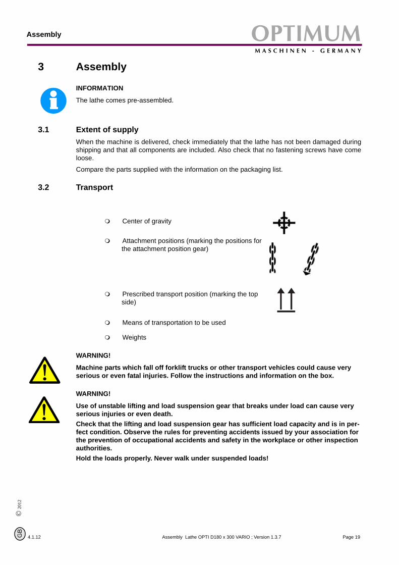
Center of gravity
Attachment positions (marking the positions for the attachment position gear)
Prescribed transport position (marking the top side)
Means of transportation to be used
Weights
Page 19Assembly Lathe OPTI D180 x 300 VARIO ; Version 1.3.7

AssemblyOPTIMUMM A S C H I N E N - G E R M A N Y
3.3 Storage
Page 20
© 2012
G
ATTENTION!
Improper storage may cause important parts to be damaged or destroyed.Store packed or unpacked parts only under the following ambient conditions.Please follow the instructions and indications on the transportation box:
Consult Optimum Maschinen Germany GmbH if the lathe and accessories have to be stored fora period of over three months or under different external conditions than those given here „Information“ on page 5.
Fragile goods (goods require careful handling)
Protect against humidity and humid environments
„Environmental conditions“ on page 18.
Prescribed position of the packaging box (marking the top side – arrows pointing upward)
Maximum stacking height
Example: non-stackable – do not pile any further pack-aging boxes on top of the first packaging box
4.1.12Assembly Lathe OPTI D180 x 300 VARIO ; Version 1.3.7
B
OPTIMUMM A S C H I N E N - G E R M A N Y
Assembly
© 2
012
GB
3.4 Installation and assembly
3.4.1 Requirements of the installation site
4.1.12
ATTENTION!
Before installing the machine, have the load bearing capacity of the subsoil checked by a specialist. The floor and the ceiling of the hall have to bear the weight of the machine plus all additional parts and additional aggregates as well as the operator and the stocked materials. Reinforce the subsoil, if necessary.
INFORMATION
In order to provide for good functionality and high machining accuracy as well as long durabilityof the machine the site should fulfill certain criteria.
Observe the following items:The device must only be installed and operated in dry ventilated places.Avoid places nearby machines generating chips or dust.The site has to be vibration-free, i.e. at a distance from presses, planing machines, etc.The substructure has to be appropriate for turning. Also make sure that the load bearing capacity and the evenness of the floor are appropriate.The substructure has to be prepared in a way that possibly used coolant cannot penetrate into the ground.Protruding parts such as stops, handles, etc. need to be secured by measures provided by the customer if necessary in order to avoid dangers for persons.Provide sufficient space for assembly and operating staff as well as for material transport.Also allow for accessibility for setting and maintenance works.Make sure that the mains plug of the turning machine is freely accessible.Provide for sufficient illumination (minimum value: 300 lux, measured at the tool tip). In case of little intensity of illumination provide for additional illumination i.e. by a separate workplace illuminator.
INFORMATION
The mains plug of the lathe has to be freely accessible.
3.4.2 Load suspension point
Fasten the load suspension gear around the lathe bed.
Make sure that you distribute the loads evenly so that the lathe cannot turn over while lifting.
Make sure that no add-on pieces or varnished parts are damaged due to the load suspen-sion.
3.4.3 Installation
WARNING!
Danger of crushing and overturning. The lathe must be installed by at least 2 people.Check the horizontal orientation of the base of the lathe with a spirit level.
Check that the foundation has sufficient floor-load capacity and rigidity.
Page 21Assembly Lathe OPTI D180 x 300 VARIO ; Version 1.3.7

AssemblyOPTIMUMM A S C H I N E N - G E R M A N Y
Page 22
ATTENTION!
Insufficient rigidity of the foundation leads to the superposition of vibrations between the machine and the foundation (natural frequency of components). Insufficient rigidity of the entire lathe assembly also rapidly causes the lathe to reach critical speeds, with unpleas-ant vibrations, leading to bad turning results.
Position the lathe on the intended foundation.
Secure the lathe to the foundation or substructure of the machine using the through holes.
„Dimensions, installation plan D180x300 Vario“ on page 18
3.5 First use
ATTENTIONBefore you begin with the commissioning on the machines check that all screws, fasten-ers and fuses are tight. If necessary they must be tightened.WARNING!
Personnel and equipment may be endangered if the lathe is first used by inexpert per-sonnel. We do not take liability for damage caused by incorrect commissioning.
3.5.1 Warming up the machine
ATTENTION!
If the lathe and in particular the lathe spindle is immediately operated at maximum load when it is cold it may result in damages.If the machine is cold such as e.g. directly after having transported the machine it should bewarmed up at a spindle speed of only 500 1/min for the first 30 minutes.
3.5.2 Cleaning and greasing
Cleaning themachine
Remove the anticorrosive agent applied to the lathe for transport and storage purposes. We recommend the use of stove distillate.
Do not use any solvents, thinners or other cleaning agents which could corrode the varnish on the lathe. Follow the specifications and indications of the manufacturer of the cleaning agent.
Lubricate all bright machine parts with non-corrosive lubricating oil.
Control thefunction of
movableand fixed
parts.
Grease the lathe using the lubrication chart. „Inspection and maintenance“ on page 66
Check smooth running of all spindles.
Control if the fastening screws of the lathe chuck are firmly tightened.
Clamp a workpiece into the lathe chuck of the lathe or bring the clamping jaws of the lathe chuck completely together before you switch on the lathe.
Make surethat the cur-rent supplyis working
correctly
© 2012
G
Connect the electrical supply cable (safety plug with earthing).
WARNING!
Do not stand directly in front of the lathe chuck when you turn on the machine for the first time.
4.1.12Assembly Lathe OPTI D180 x 300 VARIO ; Version 1.3.7
B
OPTIMUMM A S C H I N E N - G E R M A N Y
Assembly
© 2
012
GB
3.5.3 Optional accessory
4.1.12
WARNING!
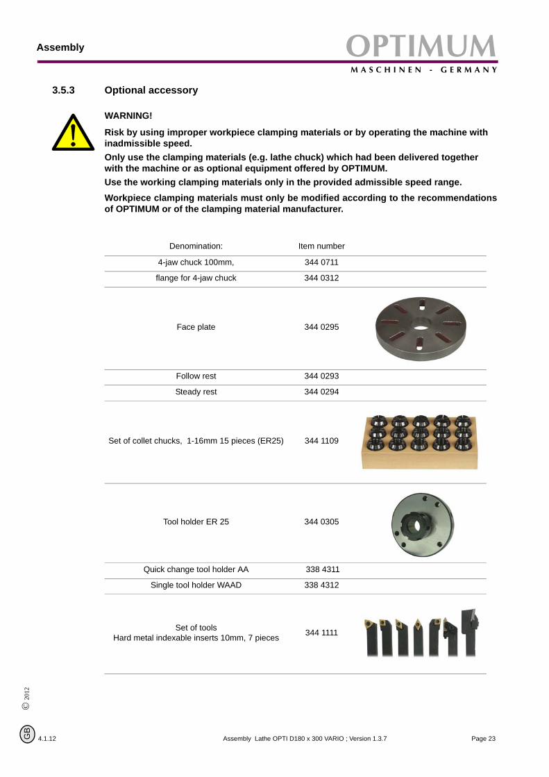
Risk by using improper workpiece clamping materials or by operating the machine with inadmissible speed.Only use the clamping materials (e.g. lathe chuck) which had been delivered together with the machine or as optional equipment offered by OPTIMUM.Use the working clamping materials only in the provided admissible speed range.Workpiece clamping materials must only be modified according to the recommendationsof OPTIMUM or of the clamping material manufacturer.
Denomination: Item number
4-jaw chuck 100mm, 344 0711
flange for 4-jaw chuck 344 0312
Face plate 344 0295
Follow rest 344 0293
Steady rest 344 0294
Set of collet chucks, 1-16mm 15 pieces (ER25) 344 1109
Tool holder ER 25 344 0305
Quick change tool holder AA 338 4311
Single tool holder WAAD 338 4312
Set of tools Hard metal indexable inserts 10mm, 7 pieces 344 1111
Page 23Assembly Lathe OPTI D180 x 300 VARIO ; Version 1.3.7

AssemblyOPTIMUMM A S C H I N E N - G E R M A N Y
Page 24
© 2012
G
Set of tools 8mm, 11 piecesTipped with hard metal 344 1008
4.1.12Assembly Lathe OPTI D180 x 300 VARIO ; Version 1.3.7
B

OPTIMUMM A S C H I N E N - G E R M A N Y
Operation
© 2
012
GB
4 Operation
4.1 Safety
4.1.12
Use the lathe only under the following conditions:
• The lathe is in proper working order.• The lathe is used as prescribed.• The operating manual is followed.• All safety devices are installed and activated.
All anomalies should be eliminated immediately. Stop the machine immediately in the event ofany abnormality in operation and make sure it cannot be started up accidentally or withoutauthorisation.
Notify the person responsible immediately of any modification.
„Safety during operation“ on page 14
4.2 Control and indicating elements
Emergency stop button
Protectivecover head-
stock
ON / OFF switch
Toolholder
Handwheel lathe saddle
Engaging switch automaticfeed
Speed table
Change-over switch withOFF position
Infinitely variablespeed adjustment
Rotation speed indicator
Handwheel top slide
Adjusting screw front
Fastening screw
Tailstock
Clamping lever of tail-stock sleeve
Jaw chuck protection
Jaw chuck
Thread and feedtable
Handwheel compoundslide
Handwheel tail-stock sleeve
Illustr.4-1: OPTI D180 x 300 VARIO
Opera
tion Lathe OPTI D180 x 300 VAR IO ; Version 1.3.7 Page 25
OperationOPTIMUMM A S C H I N E N - G E R M A N Y
4.2.1 Switching elements
Page 26
Hand actuated auxiliary switch ONThe “hand actuated auxiliary switch ON” switches the rotation of the lathe on.
Hand actuated auxiliary switch OFFThe “hand actuated auxiliary switch OFF” switches the rotation of the lathe off.
Speed adjustment
It is possible to set the required speed using the speed adjustment.
Main switch
Interrupts or connects the power supply.
Change-over switch
The direction of rotation of the lathe can be switched by actuating the change-over switch.
It is possible to select a speed for each direction of rotation.
The labeling “R” means right-handed rotation (clockwise).The labeling “L” means left-handed rotation.
ATTENTION!
Wait until the rotation of the spindle has come to complete standstill before changing the direction of rotation by actuating the change-over switch.If the direction of rotation is changed during operation, the motor and the change-overswitch might get damaged.
4.2.2 Switching on the machine
© 2012
G
Perform basic setting on the lathe (speed stage, infeed, etc.).
Check if the protective cover of the lathe chuck and the protective cover are closed – close the protective covers if necessary.
Turn the main switch on.
Select the direction of rotation.
Actuate the hand-actuated auxiliary switch “On".
4.1.12Operation Lathe OPTI D180 x 300 VARIO ; Version 1.3.7
B

OPTIMUMM A S C H I N E N - G E R M A N Y
Operation
© 2
012
GB
4.2.3 Switching off the machine
4.1.12
Actuate the hand-actuated auxiliary switch “Off”.
If the machine stands still for a longer period of time, switch off the main switch.
4.2.4 Clamping the tooln
Clamp the turning tool into the toolholder.
The tool must be clamped firmly and with the leastpossible overhang in order to absorb well andmake sure that the cutting force is reliably gener-ated during the chip formation.
INFORMATION
The maximum height between the supporting sur-face of the quadruplicate toolholder and the centerof the lathe chuck amounts to 11 mm.
Adjust the height of the tool. Use the tailstock withthe center point in order to determine its requiredheight.
If necessary, put the steel washers beneath thetool to acheive the required height.
correct
correct
incorrect
incorrect
Illustr.4-2: Clamping the tool
Operation Lathe OPTI D180 x 300 VAR
Page 27IO ; Version 1.3.7
OperationOPTIMUMM A S C H I N E N - G E R M A N Y
Page 28
The blade of the tool must be exactly adjusted tothe height of centers in order to produce a shoul-der-free front face. By facing, plain faces are beingproduced which are rectangular to the axis of rota-tion of the workpiece. Here it is distinguishedbetween cross-facing, cross-slicing and longitudi-nal facing.
correct
incorrect
Illustr.4-3: Clamping the tool
4.3 Clamping a workpiece into the lathe chuck
© 2012
G
When the workpiece is being clamped unprofessionally, there is a risk of injury as the workpiecemay fly off or the jaws may break. The following examples do not show all possible situations ofdanger.
The workpieces are to be clamped safely and tightly on the lathe before starting the operation.The clamping force is to be dimensioned in a way to make sure that the workpiece is securelydriven and that there are no dangers or deformations on the workpiece.
WARNING!
Do not clamp any workpieces that exceed the permitted chucking capacity of the lathe chuck. The clamping force of the chuck is too low if its capacity is exceeded. Also, the jaws may come loose.
incorrect correct
Clamping length too long, overhang too long.
Additional support over center.
Clamping diameter too large. Use larger lathe.
Operation Lathe OPTI D180 x 300 VARIO ; Version 1.3.7
4.1.12B

OPTIMUMM A S C H I N E N - G E R M A N Y
Operation
4.1.12
© 2
012
GB
Workpiece is too heavy and clamping grade too short.
Support over center, enlarges clamping grade.Enlarged clamping grades are not available for this three-jaw chuck.Possibly use larger lathe.
Clamping diameter too short.
Clamp on the largest clamping diameter possi-ble.
4.3.1 Replacing the clamping jaws on the lathe chuck
The clamping jaws and the three-jaw chuckare equipped with numbers. Insert the clamp-ing jaws at the correct position and in the rightorder into the three-jaw chuck.
After the replacement, bring the jaws com-pletely together in order to control if they areinserted correctly.
1 2
33
21
Illustr.4-4: Three-jaw chuck / clamping jaws
4.3.2 Head spindle seat
Illustr.4-5: Spindle flange
„Optional accessory“ on page 23
Page 29Operation Lathe OPTI D180 x 300 VARIO ; Version 1.3.7

OperationOPTIMUMM A S C H I N E N - G E R M A N Y
Page 30
© 2012
G
ATTENTION!
When disassembling the work support, it may fall on the engine bed and damage the guide rails. Put a wooden plank or another adequate part on the engine bed in order to avoid damage.
Disconnect the machine from the electrical supply.
Block the revolutions of the spindle for instance by inserting the square seat of the lathe chuck. Also make sure that the engine bed is not damaged by the arm of the lever.
Loosen the three nuts on the flange of the lathe chuck to disassemble the work support.
Remove the work support to the front.
If required, loosen the work support by knocking slight with a plastic tip or a rubber mallet.
4.1.12Operation Lathe OPTI D180 x 300 VARIO ; Version 1.3.7
B

OPTIMUMM A S C H I N E N - G E R M A N Y
Operation
© 2
012
GB
4.3.3 Mounting of follow rest
4.1.12
Illustr.4-6: Follow rest
4.3.4 Mounting of steady rest
Illustr.4-7: Steady rest
Page 31Operation Lathe OPTI D180 x 300 VARIO ; Version 1.3.7

OperationOPTIMUMM A S C H I N E N - G E R M A N Y
4.3.5 Use of collet chucks
Page 32
When using collet chucks to clamp the workpiece higher machining tolerances are available.The exchange of collet chucks for a smaller or larger diameter is simple and can be easily per-formed.
First, the collect chuck will be pressed into the ring of the union nut and has to rest there byitself. The workpiece will be clamped by fastening the union nut.
Make sure that you are using the correct collet chuck for the corresponding diameter in order tobe able to fix the workpiece safety and firmly.
„Optional accessory“ on page 23
4.4 Switching ON / OFF
CAUTION!
Check that the engaging lever is not activated when cutting threads. ( Illustr.4-13: „Engaging lever "Position OFF"“ on page 35)By switching on the lathe with high speed setting and activated engaging lever, the lathe slide will move with high speed.
ATTENTION!
Before switching on, turn the potentionmeter for speed setting to a low speed setting. The electronics may be damaged if the machine is switched on at full speed setting.The machine is switched with the ON / OFF switch. The lathe may only be switched on whenthe change-over switch is in the position "R" or "L" .
4.4.1 Change-over switch
© 2012
G
The sense of rotation of the lathe is performed by the change-over switch.
The marking "R" means right-handed rotation. The lathe chuck turns anti-clockwise.The marking "L" means left-handed rotation. In the left-handed rotation, for instance, the lathe slide is being reversed for the thread cutting. In the position "0" the engine is switched off.
ATTENTION!
Wait until the lathe has come to a complete halt before inverting the turning direction using the control levers. Changing the turning direction during operation may cause damage to components.
4.1.12Operation Lathe OPTI D180 x 300 VARIO ; Version 1.3.7
B
OPTIMUMM A S C H I N E N - G E R M A N Y
Operation
© 2
012
GB
4.5 Adjusting the speed
4.1.12
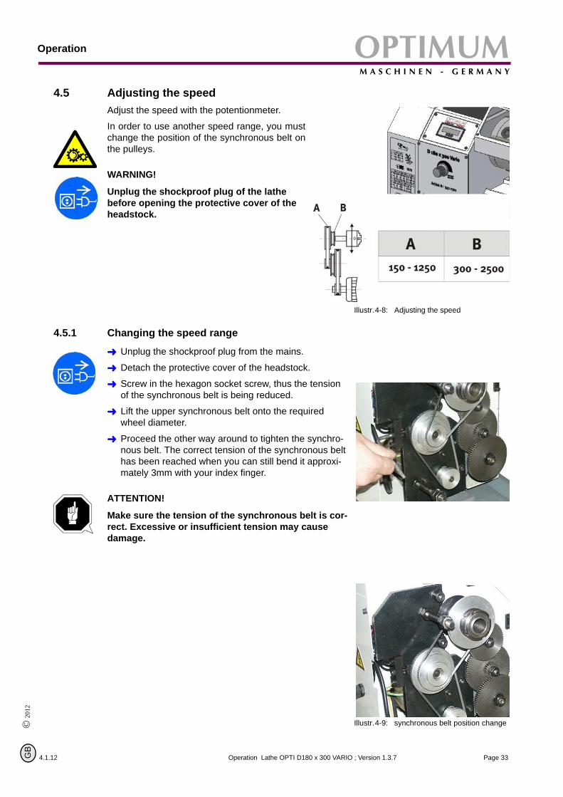
Adjust the speed with the potentionmeter.
In order to use another speed range, you mustchange the position of the synchronous belt onthe pulleys.
WARNING!
Unplug the shockproof plug of the lathe before opening the protective cover of the headstock.
Illustr.4-8: Adjusting the speed
4.5.1 Changing the speed range
Unplug the shockproof plug from the mains.
Detach the protective cover of the headstock.
Screw in the hexagon socket screw, thus the tension of the synchronous belt is being reduced.
Lift the upper synchronous belt onto the required wheel diameter.
Proceed the other way around to tighten the synchro-nous belt. The correct tension of the synchronous belt has been reached when you can still bend it approxi-mately 3mm with your index finger.
ATTENTION!
Make sure the tension of the synchronous belt is cor-rect. Excessive or insufficient tension may cause damage.
Illustr.4-9: synchronous belt position change
Page 33Operation Lathe OPTI D180 x 300 VARIO ; Version 1.3.7

OperationOPTIMUMM A S C H I N E N - G E R M A N Y
4.6 Turning between centers
Page 34
ATTENTION!
For the operation between centers check the clamping of the tailstock or of the spindle sleeve! Screw the safety screw at the end of the lathe bed in order to avoid uninten-tional pulling the tailstock out off the lathe bed.
Illustr.4-10: Lathe bed
Safety screw
4.7 Adjusting feeds and thread pitches
In order to achieve a change of feed of acertain thread pitch, the change wheels areto be changed according to the table. Youwill find the complete table on the lathe.Example:
The toothed wheel of departure with40 teeth cams in the toothed wheel AThe toothed wheel A cams in the toothed wheel CThe toothed wheel D cams in the toothed wheel FH means the vacuity (collar). You may as well use a smaller toothed wheel which does not cam in with any other toothed wheel.
Toothed wheel of depar-ture 40 teeth
Position A(Position B behind
Position A)
Position C
Position D
Position F
Position E(H) collar
Thread pitch 1,25mm
A B 52 H
C D 40 50
E F H 80
© 2012
G
Illustr.4-11: Order of the pitch 1,25mm
Operation Lathe OPTI D180 x 300 VARIO ;
V 4.1.12ersion 1.3.7B

OPTIMUMM A S C H I N E N - G E R M A N Y
Operation
4.1.12
© 2
012
GB
Example of the transmission ratio: i
The thread pitch of the leading spindle amounts to 2mm.
Example of thread pitch: 1,25mm:
Example of thread pitch: 0,75mm:
Illustr.4-12: Order of the pitch 0,75mm
60 teeth
40 teeth (standard departure)
40 teeth
45 teeth, behind60 teeth (not vissible)
80 teeth
45 teeth, behind60 teeth (not vissible)
i 2xn1xn2xn4n2xn3xn5-------------------------- 2x40xAxD
AxCxE---------------------- 2x40x52x50
52x40x80------------------------- 1 25mm,====
i 2xn1xn2xn4n2xn3xn5-------------------------- 2x40xBxD
AxDxF--------------------- 2x40x45x40
60x40x80------------------------- 0 75mm,====
Thread pitch 0,75mm
A B 60 45
C D 40
E F H 80
The toothed wheel of departure with 40 teeth cams in the toothed wheel AThe toothed wheel B cams in the toothed wheel DThe toothed wheel D cams in the toothed wheel F
INFORMATION
Metrical threads are indicated as thread pitch. In the example above, the lathe saddle moves by1.25mm during one turn of the lathe chuck. Inch threads are indicated as number of threads onthe length of one inch. The length of one inch amounts to 25.4mm.
4.7.1 Switching on the feed
CAUTION!
When switching on the lathe with high rev-olution setting and the engaging lever acti-vated, the lathe saddle moves at high speed.
Engaging leverPosition
automaticfeed "OFF"
Illustr.4-13: Engaging lever "Position OFF"
CAUTION!
If you switch on the lathe for instance at full speed of 2500min-1 with the order of the toothed wheels for thread pitch 1.25mm, the lathe saddle will travel a dis-tance of 52 mm within one second.Threads are always cut with the least pos-sible speed.
Illustr.4-14: Engaging lever "Position ON"
Engaging leverPosition
automaticfeed "ON"
Operation Lathe OPTI D180 x 300 VARI
O ; Version 1.3.7 Page 35
OperationOPTIMUMM A S C H I N E N - G E R M A N Y
4.8 General working notes
4.8.1 Coolant
Page 36
© 2012
G
Friction during the cutting process causes high temperatures at the cutting edge of the tool.
The tool should therefore be cooled during the cutting process. Cooling the tool with a suitablecooling lubricant ensures better working results and a longer edge life of the cutting tool.
INFORMATION
Use a water-soluble and non-pullutant emulsion as a cooling agent. This can be acquired fromauthorised distributors.
Make sure that the cooling agent is properly retrieved. Respect the environment when dispos-ing of any lubricants and cooling agents. Follow the manufacturer’s disposal instructions.
4.1.12Operation Lathe OPTI D180 x 300 VARIO ; Version 1.3.7
B

OPTIMUMM A S C H I N E N - G E R M A N Y
Appendix turning
© 2
012
GB
5 Appendix turning
4.1.12
Turning is a cutting manufacturing process with certain geometrically positive or negative cut-ting edge geometries.
For the machining on the outside tool holder with quadrate shaft and for the machining on theinside boring bars with rounded or oblated shafts are used (refer to ISO-code for tool holdersand boring bars).
To determine the machining direction, we distinguish between right, left and neutral tools.
On this type of lathes you generally work with right tools, as the tools are used before the centerof turning.
Machining direction for
tool holdersMachining direction for
boring bars
Illustr.5-1: right holder Illustr.5-2: right boring bar
Illustr.5-3: left holder Illustr.5-4: left boring bar
Illustr.5-5: neutral holder
For the machining of a workpiece on the outer or inner diameter tools with dif-ferent forms are required for longitudinal turning, facing, contour turning orthread cutting as well as for grooving, cutting off and cutting.
Illustr.5-6: tool holder for grooving, cutting off and cutting
Illustr.5-7: boring bar for grooving
Page 37Appendix turning Lathe OPTI D180 x 300 VARIO ; Version 1.3.7

Appendix turningOPTIMUMM A S C H I N E N - G E R M A N Y
Page 38
Illustr.5-8: tool holder for thread cutting Illustr.5-9: boring bar for thread cutting
5.1 ISO-designation system for tool holder, inside machining
clamped at the top
clamped at the topabove the hole
clamped above the hole
screwed throughthe hole
Type of fixtureMaterial of the body Shank diameter Tool length
081012162025324050
Identification letters for the length
ABCDEFGHJKLMNPQRSTUVWXY
32 mm40 mm50 mm60 mm70 mm80 mm90 mm100 mm110 mm125 mm140 mm150 mm160 mm170 mm180 mm200 mm250 mm300 mm350 mm400 mm450 mmspecial length500 mm
Identification Material Construction of the body
S steel cutter none
A with inner coolantfeeding
B with vibrationdamping
D with vibration damping and inner coolant
hard metal none
with inner coolant feeding
with vibrationdamping
with vibrationdamping and inner coolant feeding
cutter withsteel head
C
E
F
G
heavy metal none
with inner coolantfeeding
H
J
letter features
feeding
© 2012
G
4.1.12Appendix turning Lathe OPTI D180 x 300 VARIO ; Version 1.3.7
B

OPTIMUMM A S C H I N E N - G E R M A N Y
Appendix turning
© 2
012
GB
5.2 ISO-designation system for tool holder, outside machining
clamped at the top
clamped at the topabove the hole
clamped above the hole
screwed through the hole
free angles where specialindications are requiired
Type of fixture Form of the indexable insert Form of the tool holder Free angle of the indexab
4.1.12 Page 39Appendix turning Lathe OPTI D180 x 300 VARIO ; Version 1.3.7

Appendix turningOPTIMUMM A S C H I N E N - G E R M A N Y
5.3 Cutter with hard metal reversible carbide tip soldered on
Page 40
Lathe tools made of high-speed steel (HSS) and lathe tools with hard metal tips soldered on aresolid tools. The cutting edge geometry is to be ground for the corresponding machining.
„Grinding or regrinding of cutting edge geometries of turning tools“ on page 61
For tool holders with indexable inserts the cutter geometry of the tool holder and of the corre-sponding indexable insert is given. For this type of tools there are four types of ficture for theindexable inserts „ISO-designation system for tool holder, outside machining“ on page 39
Illustr.5-10: straight cutter DIN 4971ISO 1
Illustr.5-11: bent cutter DIN 4972ISO 2
Illustr.5-12: inside tool DIN 4973ISO 8
Illustr.5-13: internal side turning tool for corner work DIN 4974 ISO 9
Illustr.5-14: tip of cutter DIN 4975 Illustr.5-15: cutter width DIN 4976ISO 4
Illustr.5-16: offset face turning tool DIN 4977ISO 5
Illustr.5-17: offset tool for corner work DIN 4978ISO 3
Illustr.5-18: offset side turning tool DIN 4980ISO 6
Illustr.5-19: cuttoff tool DIN 4981ISO 7
5.4 Cut the first chips
© 2012
G
In order to cut the first chips, a tool holder for the outside machining and a cutter bar for theinside machining are required. Furthermore, some twist drills (HSS) are required to centricallydrill the part to be turned.
For the "do-it-yourselfer" it is recommended to use lathe tools with indexable inserts andscrewed clamping. The lathe tool does not require grinding and the indexable insert have a posi-tive cutting form level.
Before you can set the tools you have to determine the shank height and width respectively theshank diameter.
The indicated height of centers is the measure from the cutting point to the lathe bed. As there isno tool holder yet, the difference in height is to be determined from the bearing surface of thetool holder in the quadraple holder to the rotation axis. For some machines, the difference inheight to the rotation axis is indicated in the technical data.
For tools according to ISO or DIN, the shank height is equal to the height of the cutting point.After clamping the tool holder, the height of the cutting point is to be checked. For drill rods
4.1.12Appendix turning Lathe OPTI D180 x 300 VARIO ; Version 1.3.7
B

OPTIMUMM A S C H I N E N - G E R M A N Y
Appendix turning
4.1.12
© 2
012
GB
according to ISO, the height of the cutting point is half the shank diameter and for flattened drillrods half the flattened height. For inside tools according to DIN the height of th cutting point cor-responds to 0,8 x shank diameter respectively shank height.
ATTENTION!
If due to a variation in tolerance there is a slug or cone on the plane face, the exact height ofcenters is to be found by facing trials (put the tool holder higher for slugs and lower for cones).
The height of centers is to be checked each time when the turning tools are changed!
For example, a shaft with a diameter of 30mm is to be machined of C45. The outside diameter isto be turned and faced 20mm and a hole of 16mm is to be drilled.
Selecting the tools
tool holder for turningand facing with 95° tool cutting edge angle indexable insert with a point angle of 80°we select a coated hard metal HC M15/K10 as cutting material. With this tool about 75% of all lathe work on the outside diameter may be performed.
Selecting the cutting data
A hard metal with the designation HC M15/K10 is selected as cutting material, cutting speed ϑc = 80 m/minap = 0,4mm for outside machining; ap = 0,2 mm for inside machining f = 0,05 mm/U (value for automatic feed)
The speed which is to be set is calculated with
the formular
n ϑc 1000×d 3 14,×
------------------------- 80 1000×30 3 14,×------------------------ 849min 1–
===
Page 41Appendix turning Lathe OPTI D180 x 300 VARIO ; Version 1.3.7

Appendix turningOPTIMUMM A S C H I N E N - G E R M A N Y
5.5 Outside machining, longitudinal turning and facing
Page 42
For longitudinal turning, the tool holder is moved parallel to the rotation axis. The feed is per-formed by turning the handwheel of the slide (therefore the bedslide is to be fixed with theclamping screw). Furthermore you have to pay attention that the angular scale of the compoundslide is set to zero so that no tapers are being produced.
The feed may also be performed automatically over the leading spindle by shifting the operatinglever of the leadscrew nut. Pay attention that the feed is not automatically switched off.
Switching off is to be done manually!
Pay also attention to the correct gear pairing!
The infeed of the depth of cut is performed over the handwheel of the compound slide in direc-tion to the rotation axis.
Illustr.5-20: longitudinal turning
feed direction
depth of cut infeed
For facing the bedslide is to be fixed with the clamping screw. The feed is performed by turningthe handwheel of the compound slide. The infeed of the depth of cut is performed with the hand-wheel of the compound slide.
Illustr.5-21: facing
depth of cut infeed
feed direction
5.6 Inside machining, drilling and longitudinal turning
© 2012
G
Selecting the tools
drill chuck with morse cone seat twist drill with center drill drill rod with 95° tool cutting edge angle. This drill rod has a shank diameter of 8,0mm, e.g. a cutting point height of 4,0mm. For a drill rod shank with a flattening at the top, a support may be put beneath the tool in order to achieve the require height of centers. If the drill rod has got a streight shank, a prison or a special streight shank seat is required. For drill rods please take into account that there is a predetermined minimum turning diame-ter in this example of 11mm.The advantage in selecting these tools is that you may use the same indexable inserts as for the outside machining. .With this tool you may perform about 75% of the lathe work on the inside diameter. In order to machine centric holes on the lathe, twist drills (HSS) are required. Furthermore a drill chuck with a chucking capacity of 1 to 13mm or 3-16mm with a more cone seat (example morse cone seat of the size 2) is required. The drill chuck with the morse cone seat is held by the tailstock sleeve and the twist drills are clamped into the drill chuck. The feed for drilling is performed after clamping the tailstock to its position with the handwheel on the tailstock sleeve. To make sure that the twist drill will not run off center when spot-drilling, the workpiece is to be centered with a center drill. For holes from 6,0mm onward you should predrill with a
Append
4.1.12ix turning Lathe OPTI D180 x 300 VARIO ; Version 1.3.7B

OPTIMUMM A S C H I N E N - G E R M A N Y
Appendix turning
4.1.12
© 2
012
GB
smaller drill. The drill diameter must be as large as the core diameter of the drill of the hole diameter which is to be drilled! A 4,0mm and a 11,5mm drill are used. With the drill rod only the predetermined diameter is followed. The feed is performed by turn-ing the handwheel of the compound slide paralell to the rotation axis (please also follow the indications for longitudinal turning. The infeed of the cutting depth is performed with the hand-wheel of the compound slide in direction away from the center. Please make sure that the drill rods are clamped as short as possible (to avoid oscillations). You may assure a projection length from the drill rod seat of 4 x drill hole diameter as an empirical formula.
5.7 Tapping of external and internal threads
Threads with smaller diameters and standard thread pitches should be tapped manually on thelathe with screw-taps or dies by turning the clamping chuck as this is more simple to produce.ATTENTION !
Pull off the mains plug of the lathe if you want to tap a thread as described above.
Illustr.5-22: die Illustr.5-23: screw tap
Bolts and nuts with large thread diameters, deviating thread pitches or special types of thread,right-handed and left-handed threads may be produced by threading. For this manufacturingthere are as well tool holders and drill rods with exchangeable indexable inserts (one-edged ormultiple-edged).
Illustr.5-24: tap external thread Illustr.5-25: tap internal thread
Page 43Appendix turning Lathe OPTI D180 x 300 VARIO ; Version 1.3.7

Appendix turningOPTIMUMM A S C H I N E N - G E R M A N Y
5.7.1 Thread types
Page 44
© 2012
G
Designation Profile Code letter Short term (e. g.) Application
ISO-thread MUN
UNC UNF
UNEF UNS
M4x12
1/4" - 20UNC - 2A
0,250 - UNC - 2A
Mac
hine
tool
s an
d ge
nera
l mec
hani
cal e
ngin
eerin
g
UNJ UNJ 1/4" - 20UNJ
Airc
raft
indu
stry
and
aer
ospa
ce
Nut
Bolt
Nut
Bolt
4.1.12Appendix turning Lathe OPTI D180 x 300 VARIO ; Version 1.3.7
B
OPTIMUMM A S C H I N E N - G E R M A N Y
Appendix turning
© 2
012
GB
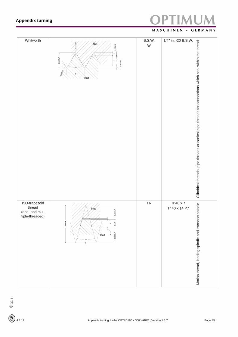
Whitworth B.S.W.W
1/4" in. -20 B.S.W.
Cilin
dric
al th
read
s, p
ipe
thre
ads
or c
onic
al p
ipe
thre
ads
for c
onne
ctio
ns w
hich
sea
l with
in th
e th
read
ISO-trapezoid
thread(one- and mul-tiple-threaded)
TR Tr 40 x 7 Tr 40 x 14 P7
Mot
ion
thre
ad, l
eadi
ng s
pind
le a
nd tr
ansp
ort s
pind
le
Nut
Bolt
Nut
Bolt
4.1.12 Page 45Appendix turning Lathe OPTI D180 x 300 VARIO ; Version 1.3.7

Appendix turningOPTIMUMM A S C H I N E N - G E R M A N Y
© 2012
G
Round thread RD RD DIN 405
Fitti
ngs
and
for p
urpo
ses
of th
e fir
e br
igad
e
NPT NPT 1“ – 11 ½“ NPT
Fitti
ngs
and
tube
join
ts
Nut
Bolt
Nut
Bolt
Kegel
4.1.12Page 46 Appendix turning Lathe OPTI D180 x 300 VARIO ; Version 1.3.7
B

OPTIMUMM A S C H I N E N - G E R M A N Y
Appendix turning
© 2
012
GB
5.7.2 Metric thread (60° flank angle)
pitch P
depth of thread of the bolt h2=0,6134 x P
depth of thread of the nut h1 = 0,5413 x P
rounding r = 0,1443 x P
flank diameter d2 = D2 =d - 0,6493
core removing hole drill = d - P
flank angle = 60°
Metric coarse-pitch thread
Sizes in mm: preferably use the threads in column 1
Denomination of thread d = D
Pitc
h P
Flan
k di
amet
er
d2 =
D2
Core diameter Depth of thread
Rou
ndin
g r
Cor
e re
mov
ing
hole
dril
l
Column 1 Column 2 Boltd3
NutD1
Bolth3
NutH1
M 1 0,25 0,838 0,693 0,729 0,153 0,135 0,036 0,75
M 1,1 0,25 0,938 0,793 0,829 0,153 0,135 0,036 0,85
M 1,2 0,25 1,038 0,893 0,929 0,153 0,135 0,036 0,95
M 1,4 0,3 1,205 1,032 1,075 0,184 0,162 0,043 1,1
M 1,6 0,35 1,373 1,171 1,221 0,215 0,189 0,051 1,3
M 1,8 0,35 1,573 1,371 1,421 0,215 0,189 0,051 1,5
M 2 0,4 1,740 1,509 1,567 0,245 0,217 0,058 1,6
M 2,2 0,45 1,908 1,648 1,713 0,276 0,244 0,065 1,8
M 2,5 0,45 2,208 1,948 2,013 0,276 0,244 0,065 2,1
M 3 0,5 2,675 2,387 2,459 0,307 0,271 0,072 2,5
M 3,5 0,6 3,110 2,764 2,850 0,368 0,325 0,087 2,9
M 4 0,7 3,545 3,141 3,242 0,429 0,379 0,101 3,3
M 5 0,8 4,480 4,019 4,134 0,491 0,433 0,115 4,2
M 6 1 5,350 4,773 4,917 0,613 0,541 0,144 5,0
M 8 1,25 7,188 6,466 6,647 0,767 0,677 0,180 6,8
M 10 1,5 9,026 8,160 8,376 0,920 0,812 0,217 8,5
M 12 1,75 10,863 9,853 10,106 1,074 0,947 0,253 10,2
M14 2 12,701 11,546 11,835 1,227 1,083 0,289 12
M 16 2 14,701 13,546 13,835 1,227 1,083 0,289 14
M18 2,5 16,376 14,933 15,294 1,534 1,353 0,361 15,5
M 20 2,5 18,376 16,933 17,294 1,534 1,353 0,361 17,5
M 22 2,5 20,376 18,933 19,294 1,534 1,353 0,361 19,5
M 24 3 22,051 20,319 20,752 1,840 1,624 0,433 21
M 27 3 25,051 23,319 23,752 1,840 1,624 0,433 24
M 30 3,5 27,727 25,706 26,211 2,147 1,894 0,505 26,5
M 36 4 33,402 31,093 31,670 2,454 2,165 0,577 32
Nut
Bolt
4.1.12 Page 47Appendix turning Lathe OPTI D180 x 300 VARIO ; Version 1.3.7

Appendix turningOPTIMUMM A S C H I N E N - G E R M A N Y
© 2012
G
M 42 4,5 39,077 36,479 37,129 2,760 2,436 0,650 37,5
M 48 5,5 44,752 41,866 41,866 3,067 2,706 0,722 43
M 56 5,5 52,428 49,252 49,252 3,374 2,977 0,794 50,5
M 64 6 60,103 56,639 56,639 3,681 3,248 0,866 58
Metric fine-pitch thread
Denomination of thread
d x P
Flank diame-ter d2 = D2
Core diameter Denomina-tion of
thread d x P
Flankdiameter d2 = D2
Corediameter
Bolt Nut Bolt Nut
M2 x 0,2 1,870 1,755 1,783 M16 x 1,5 15,026 14,160 14,376
M2,5 x 0,25 2,338 2,193 2,229 M20 x 1 19,350 18,773 18,917
M3 x 0,35 2,773 2,571 2,621 M20 x 1,5 19,026 18,160 18,376
M4 x 0,5 3,675 3,387 3,459 M24 x 1,5 23,026 22,160 22,376
M5 x 0,5 4,675 4,387 4,459 M24 x 2 22,701 21,546 21,835
M6 x 0,75 5,513 5,080 5,188 M30 x 1,5 29,026 28,160 28,376
M8 x 0,75 7,513 7,080 7,188 M30 x 2 28,701 27,546 27,835
M8 x 1 7,350 6,773 6,917 M36 x 1,5 35,026 34,160 34,376
M10 x 0,75 9,513 9,080 9,188 M36 x 2 34,701 33,546 33,835
M10 x 1 9,350 8,773 8,917 M42 x 1,5 41,026 40,160 40,376
M12 x 1 11,350 10,773 10,917 M42 x 2 40,701 39,546 39,835
M12 x 1,25 11,188 10,466 10,647 M46 x 1,5 47,026 46,160 46,376
M16 x 1 15,350 14,773 14,917 M48 x 2 46,701 45,546 45,835
4.1.12Page 48 Appendix turning Lathe OPTI D180 x 300 VARIO ; Version 1.3.7
B

OPTIMUMM A S C H I N E N - G E R M A N Y
Appendix turning
© 2
012
GB
5.7.3 British threads (55° flank angle)
4.1.12
BSW (Ww.): British Standard Withworth Coarse Thread Series is the most common coarse-pitchthread in Great Britain and corresponds in its usage category to the metric coarse-pitch thread.The designation of a hexagon head screw 1/4" - 20 BSW x 3/4" , is here: 1/4" is the nominaldiameter of the screw and 20 is the number of threads in 1" of length.
BSF: British Standard Fine Thread Series. BSW- and BSF are the thread selection for the com-mon screws. This fine thread is very common in the British machine tool industry, but it isreplaced by the American UNF thread.
BSP (R): British Standard Pipe Thread. Cylindric pipe thread; designation in Germany: R 1/4"(nominal width of the tube in inch). Tube threads are larger in their diameter as "BSW". Designa-tion 1/8" - 28 BSP
BSPT: British Standard Pipe - Taper Thread. Conic tube thread, cone 1:16; designation: 1/4" - 19BSPT
BA: British Association Standard Thread (47 1/2° flank angle). Common with instruments andwatches, is being replaced by the metric ISO thread and by the ISO miniature thread. It consistsof numeric designations from 25 to 0=6,0mm max diameter.
Table of the British threads
Nominal diameter of the thread
Threads in 1" Threads in 1"
BSW BSF BSP/BSPT BA-threads
Inch mm (R) D. [mm] Nr. D.[mm]
55° Flank angle 47 1/2° Flank angle
1/16 1,588 60 - - 16 134 0,79
3/32 2,382 48 - - 15 121 0,9
1/8 3,175 40 - 28 9,73 14 110 1,0
5/32 3,970 32 - - - 13 102 1,2
3/16 4,763 24 32 - - 12 90,9 1,3
7/32 5,556 24 28 - - 11 87,9 1,5
1/4 6,350 20 26 19 13,16 10 72,6 1,7
9/32 7,142 20 26 - - 9 65,1 1,9
5/16 7,938 18 22 - - 8 59,1 2,2
3/8 9,525 16 20 19 16,66 7 52,9 2,5
7/16 11,113 14 18 - - 6 47,9 2,8
1/2 12,700 12 16 14 20,96 5 43,0 3,2
9/16 14,288 12 16 - - 4 38,5 3,6
5/8 15,875 11 14 14 22,91 3 34,8 4,1
11/16 17,463 11 14 - - 2 31,4 4,7
3/4 19,051 10 12 14 26,44 1 28,2 5,3
13/16 20,638 10 12 - - 0 25,3 6,0
Page 49Appendix turning Lathe OPTI D180 x 300 VARIO ; Version 1.3.7

Appendix turningOPTIMUMM A S C H I N E N - G E R M A N Y
7/8 22,226 9 11 14 30,20
15/16 23,813 9 11 - -
1" 25,401 8 10 11 33,25
1 1/8 28,576 7 9 - -
1 1/4 31,751 7 9 11 41,91
1 3/8 34,926 6 8 - -
1 1/2 38,101 6 8 11 47,80
1 5/8 41,277 5 8 - -
1 3/4 44,452 5 7 11 53,75
1 7/8 47,627 4 1/2 7 - -
2" 50,802 4 1/2 7 11 59,62
Page 50
5.7.4 Indexable inserts
For indexable inserts there are partial profile and full profile indexable inserts. The partial profileindexable inserts are designed for a certain pitch range (e.g. 0,5 - 3mm).
The partial profile indexable insert is optimally appropriate for the single-piece production.The full profile indexable insert is only designed for a certain pitch.
Illustr.5-26: partial profile indexable insert Illustr.5-27: full profile indexable insert
© 2012
G
Determining the machining method of right-handed and left-handed threads:
Right-handed tool holders or drill rods are used. In order to top right-handed threads the feeddirection towards the clamping chuck is selected and the machine spindle turns to the right (theturning direction of the machine spindle is determined when you look into the spindle from therear side). If a left-handed thread is to be tapped, the feed direction is selected away from theclamping chuck in direction to the tailstock and the machine spindle turns to the right.
4.1.12Appendix turning Lathe OPTI D180 x 300 VARIO ; Version 1.3.7
B

OPTIMUMM A S C H I N E N - G E R M A N Y
Appendix turning
4.1.12
© 2
012
GB
Illustr.5-28: right-handed thread with the machine spindle turning to the right
Illustr.5-29: left-handed thread with the machine spindle turning to the right
feed direction feed direction
As for thread cutting there are other conditions as for longitudinal turning, the forward cuttermust show a larger charance as the pitch angle of the thread.
Illustr.5-30: Pitch angle
Pitch angle
Pitch P
Cor
e di
amet
er
Flan
k di
amet
er
Thre
ad d
iam
eter
ϕ
ϕtan PD2 π×-----------------=
Page 51Appendix turning Lathe OPTI D180 x 300 VARIO ; Version 1.3.7

Appendix turningOPTIMUMM A S C H I N E N - G E R M A N Y
5.7.5 Examples for thread cutting
Page 52
As an example, a metric external thread M30 x 1,0 mm made of brass is being machined.
Selecting the tool holder
For lathe D140 and D180, turning tool No.6 and for lathe D210, D240, D250, D280 turning toolNo.13.
Pointing turning tools are also appropriate ( „tip of cutter DIN 4975“ on page 40) with hardmetal plates soldered on of the complete set for the lathe D140 and D180, 8mm, 11-pieces, itemNo. 344 1008 and for lathe D210, D240, D250, D280, 8mm, 11-pieces, item No. 344 1108 .
The above mentioned thread turning tools have a point angle of 60°.
Set of turning tools HM 8mm 344 10117-pieces with HM indexable insertsTiN-coated in a wooden case ISO designation tool holder Turning tool 1: SWGCR/L0810D05Turning tool 2: SCLCR/L0810D06Turning tool 3: SDJCR/L0810D07Turning tool 4: SDNCN/L0810D07Turning tool 5: SCLCL0810D06Turning tool 6: LW0810R/L 04Turning tool 7: QA0812R/L03
Set of turning tools HM 10mm344 11117-pieces with HM indexable inserts TiN-coated in a wooden case ISO designation tool holder Turning tool 8: SWGCR/L1010E05Turning tool 9: SCLCR1010E06Turning tool 10: SDJCR/L1010E07Turning tool 11: SDNCN/L1010E07Turning tool 12: SCLCR/L1010E06Turning tool 13: LW1010R/L04Turning tool 14: QA1012R/L03
1 2 3 4 5 6 7
8 9 10 11 12 13 14
Steel sheets are to be laid under the complete tool holder or turning tool to achieve exactly the turning center.
The lowest spindle speed is set so that the lathe will not coast too long !
Mount gear pairing for pitch 1,0mm in the change gear !
© 2012
G
Illustr.5-31: Threading
The outer diameter had been turned to 30,0mm and thetool holder is clamped in the quadraple holder for thread-ing aligned angular to the rotation axis. The height ofcenters is checked (as described).
4.1.12Appendix turning Lathe OPTI D180 x 300 VARIO ; Version 1.3.7
B

OPTIMUMM A S C H I N E N - G E R M A N Y
Appendix turning
4.1.12
© 2
012
GB
Illustr.5-32: radial infeed
The depth of thread is manufactured invarious passes. The infeed is to bereduced after each pass.
The first pass takes place with an infeed of0,1 to 0,15mm.
For the last pass the infeed shall not bebelow 0,04mm.
For pitches up to 1,5mm the infeed maybe radial.
For our example 5 to 7 passes are beingdetermined.
Illustr.5-33: alternate infeed
For larger pitches the alternate flankinfeed is selected. The compound slide isoffset alternately to the left and to the rightby 0,05 to 0.10mm each. The last twopasses are performed without lateral off-set. When the depth of thread is achieved,two passes are performed without infeed.
To machine internal threads, about 2passes shall be selected additionally forthe infeed (drill rods are more instable).
The cutting point is slit slightlym by turning the handwheel of the compound slide the scale isturned to zero. This is the point of departure for the infeed of the depth of thread.
The scale of the compound slide is also set to zero (this is important for the lateral offset whenturning threads with larger pitches).
The cutting point is set just in front of the starting point of the start of the thread by actuating thehandwheel of the bedslide.
In standstill of the lathe a connection to the leadspindle is made by shifting the operating lever ofthe lead-screw nut. With this connection, the adjusted thread pitch is transfered to the bedslideand to the tool holder.
ATTENTION !
This connection must not be disconnected until the thread is finished !
Page 53Appendix turning Lathe OPTI D180 x 300 VARIO ; Version 1.3.7

Appendix turningOPTIMUMM A S C H I N E N - G E R M A N Y
Page 54
Starting the threading:
Radial infeed over the handwheel of the compound slide. Turn the change-over, switch to the right. Start the machine and have the first cutting process run.
ATTENTION !
Always have the thumb ready on the OFF-switch in order to prevent a collision with the work-piece or with the clamping chuck !
Immediately turn off the machine at the runout of the thread and cam the cutter out by turning the handwheel of the compound slide. Turn the change-over, switch to the left. Turn the machine on and return the bedslide to the starting point and switch the machine off. Radial infeed over the handwheel of the compound slide.Turn the change-over, switch to the right. Switch the machine on and have the second cutting process run. Repeat this proceedure as often as necessary until the depth of thread is achieved. To check the thread you may use a thread gauge or a workpiece with an internal thread M30 x 1,0.If the thread is having the exact size, the thread cutting process may be terminated. Now you may again shift the operating lever of the lead-screw nut in standstill. In this way, the connec-tion between the lead spindle and the bedslide is interrupted. Now the toothed wheels for the longitudinal feed are to be mounted again !
5.8 Recessing, cutting off and turning off
When recessing, grooves at the outer or inner diameter are manufactured e.g. for o-rings andlocking rings. There is also the possibility to manufacture recesses on the plane face.When cutting off the finished workpiece is separated from the feed stock.
The turning off is a combination of recessing and longitudinal turning.
For each of these machining methods there are indexables inserts with sintered cutting form lev-els available.
© 2012
G
Illustr.5-34: outside recessing Illustr.5-35: recessing on plane faces
Illustr.5-36: cutting off, turning off Illustr.5-37: inside recessing
4.1.12Appendix turning Lathe OPTI D180 x 300 VARIO ; Version 1.3.7
B

OPTIMUMM A S C H I N E N - G E R M A N Y
Appendix turning
4.1.12
© 2
012
GB
Illustr.5-38: recessing 1 Illustr.5-39: recessing 2
On a shaft made of brass, an undercut for a thread M30 is to be machined. Groove with 5,0mmwith a depth of 2,5mm.
Selecting the tool holder: For lathe D140 and D180, turning tool No.7, and for lathe D210,D240, D250, D280 turning tool No. 14
For small lathes the cutting speed for this machining compared to the cutting speed for longitudi-nal turning is reduced by about 60% in order to prevent oscillations.
Cutting speed Vc = 40 m/min, the speed to be set would be 425min-1 .
The tool holder is clamped into the quadraple holder, aligned angular to the rotation axis and theheight of centers is checked.
The tool is positioned and fixed with the bedslide. The exact position is set with the handwheelof the compound slide. With the indexable insert the outer diameter is slit slightly (by turning thehandwheel of the compound slide). Set the scale to zero and the first recess of 3,0mm widthmay be machined. Apply some machine oil on the cutter to grease it! Another recess of 2,0mmis required to achieve a groove width of 5,0mm.
Page 55Appendix turning Lathe OPTI D180 x 300 VARIO ; Version 1.3.7

Appendix turningOPTIMUMM A S C H I N E N - G E R M A N Y
5.9 Turning cones with high precision
Page 56
Illustr.5-40: designations on the cone
D = large diameter [mm]
d = small diameter [mm]
L = cone length [mm]
Lw = workpiece length [mm]
= cone angle
= setting angle
Kv = cone proportion
Vr = tailstock offset
Vd = measure change [mm]
Vo = twist measure of compound slide [mm]
α
α 2⁄
D d
Lw
L
α
α 2⁄
There are different possibilities to machine a cone on a common small lathe:
1. By twisting the compound slide and by setting the setting-angle with theangular scale. But there the graduation of the scale is too inaccurate. For chamfers and conic pas-sings the graduation of the angular scale is sufficient.
2. By a simple calculation, a stop measure of 100mm length (of your own production)and a gauge with stand.
Calculation
of the offset of the top slide relating to the stop measure with a length of 100mm.
step by step
by one calculation step (summary)
example:
D = 30,0mm ; d = 24,0mm ; L = 22,0mm
Kv LD d–-------------= Vd 100mm
Kv-------------------= Vo Vd
2-------=
Vo 100mm D d–( )×2 L×
-------------------------------------------=
Vo 100mm 30mm 24mm–( )×2 22mm×
-------------------------------------------------------------------- 100mm 6mm×44mm
-------------------------------------- 13= 63mm,==
© 2012
G
The stop measure (100mm) is to be put between a fixed lunit stop and the bedslide. Put thegauge with stand on the lathe bed and horizontally align the test prod with the testprod with thecompound slide (90° to the compound slide). The twisting measure is calculated with the abovementioned formula. The compound slide is twisted by this value (then set the gauge to zero).
Appe
ndix turning 4.1.12 Lathe OPTI D180 x 300 VARIO ; Version 1.3.7B

OPTIMUMM A S C H I N E N - G E R M A N Y
Appendix turning
4.1.12
© 2
012
GB
After removing the stop measure, the bedslide will be aligned to the limit stop. The gauge mustindicate the calculated value "Vo". Then the workpiece and the tool are clamped and positioned(the bedslide is fixed). The infeed is performed with the handwheel of the compound slide. Thedepth of cut is advanced with the handwheel of the compound slide.
Illustr.5-41: Cone setting with stop measure
Gauge
Stop measure 100mm
Limit stop
Measuring direction Advance of depth of cut
Infeed direction
3. By measuring an existing cone with gauge and stand
The stand is put on the compound slide. The gauge is aligned horizontally and 90° to the com-pound slide. The compound slide is approximately adjusted to the cone angle and the test prodbrought in contact with the cone surface (fix the bedslide). Now the compound slide is twisted ina way that the gauge does not indicate any travel of the pointer over the whole length of thecone (offset over the handwheel of the compound slide).
Then you may start reaming the lathe as described under point 2. The workpiece might be aflange for lathe chucks or a face plate.
Illustr.5-42: determining the cone with a gauge
Gauge
Advance of depth of cut
Measuring- andinfeed direction
Page 57Appendix turning Lathe OPTI D180 x 300 VARIO ; Version 1.3.7

Appendix turningOPTIMUMM A S C H I N E N - G E R M A N Y
Page 58
4. By offsetting the tailstock as the cone length is larger than the adjustable stroke ofthe compound slide.
The workpiece is clamped between two points, therefore center holes are required on the face.They are to be drilled before removing the lathe chuck. The slaving of the workpiece is per-formed by a pulling pin and a lathe carrier.
The calculated value "Vr" is the offset measure of the tailstock. The offset is monitored with thegauge (also the return travel). „designations on the cone“ on page 56
For this type of cone machining the lowest speed is used !
Annotation:
In order to check the position of the tailstock axis to the rotation axis, a shaft with two centeringsis clamped between the points. The stand with the gauge is put on the bedslide. The gauge isaligned 90° to the rotation axis and horizontally brought into contact with the shaft. The gaugewill pass along the shaft with the bedslide. There must not be any travel of the pointer along thewhole length of the shaft. If a deviation is being shown, the tailstock is to be corrected.
Calculation:
or
The tailstock offset must not exceed the value "Vrmax" as the workpiece tumbles !
Example:
Kv = 1 : 40 ; Lw = 150mm ; L = 100mm
Vr Lw2 Kv×----------------= Vr D d–
2 L×------------- Lw×=
VrmaxLw50--------=
Vr 1502 40×--------------- 1 875mm,= = Vrmax
15050--------- 3mm==
Illustr.5-43: Workpiece between points: tailstock offset Vr
© 2012
G
4.1.12Appendix turning Lathe OPTI D180 x 300 VARIO ; Version 1.3.7
B

OPTIMUMM A S C H I N E N - G E R M A N Y
Appendix turning
© 2
012
GB
5.10 Cutting material
4.1.12
The basic requirement for a cutting material is that it is harder than the material which is to beworked. The larger the difference is, the higher the wear resistance of the cutting material.
5.10.1 Cutting materials for chipping
High-speed steel (HSS)
High-speed steel is a high-alloy tol steel with high tenacy. The cutting edges may be groundsharp-edged and the tools may be used with low cutting speed.
Hard metal (uncoated and coated)
Hard metal is a sintered material on the basis of tungsten carbide which may be applied foralmost all materials which are to be chipped due to the different composition. There are somemore wear-resistant types of hard metal and others with a higher tenacy.
The hard metals are divided into three main groups:
P - for long-chipping materials (steel, meltable cast iron)
M - for long- and short-chipping material (stainless steel, machining steel)
K - for short-chipping materials (castiron, NE metals, hardened steel)
An additional classification is performed with an annexed figure:
The lower the figure (P10), the higher is the wear resistance (planing)
The higher the figure (P40), the higher the tenacy (roughing).
In order to make hard metals more wear resistant, they may be coated with mechanically resist-ant materials. These layers may be applied as single or multiple-layer coatings.
There are two proceedures:
PVD / Physical Vapor Deposition,CVD / Chemikal Vapor Deposition.
The most common layers of mechanically resistant materials are:
TiN / titanium nitride,TiC / titanium carbide,TiCN / titanium carbon nitride,Al2O3 / aluminum oxide,
as well as their combinations
The PVD-coated indexable inserts have sharper cutting edges and thus lower cutting forces.Also well appropriate for small lathes.
Cermet (uncoated and coated)
Cermet (ceramic-metal) is a hard metal on the basis of titanium carbide. The cutting materialhas very good wear resistance and edge strength. Indexable inserts made of Cermet are usedwith high cutting speeds for planing.
Cutting ceramics
Cutting ceramics is composed of non-metalic anorganic material.
Oxide ceramics on the basis of aluminum oxide and an addition of zircon. The main applicationis the machining of cast iron.
Mixed ceramics made of aluminum oxide an addition of titanium carbide has good a wearresistance on the edge strength. This cutting material is applied in the machining of chill casting.
Page 59Appendix turning Lathe OPTI D180 x 300 VARIO ; Version 1.3.7
Appendix turningOPTIMUMM A S C H I N E N - G E R M A N Y
Page 60
Non-oxide ceramics on the basis of silicon nitride is insensible against thermal shock (it may beused with coolants). Non-alloy cast iron is chipped.
Cubic boron nitride (CBN)
Cubic boron mitride has a high tenacy and a good high temperature strength. It is appropriatefor the planing of hardened materials.
Polycrystalline diamond (PKD)
Polycrystalline diamond has a good wear resistance. Good surface qualities with stable cuttingconditions are being achieved. Fields of application are nonferrous and non-metallic materials inthe finishing.
For other application references please refer to the documents of the tools’ manufacturer.
5.11 Standard values for cutting data when turning
© 2012
G
The better the cutting data are selected, the better the turning result. Some standard values forcutting speeds of different materials are listed on the following pages. „Cutting speed table“on page 61
Criteria of the cutting conditions:
Cutting speed: Vc (m/min)
Depth of cut: ap (mm)
Infeed: f (mm/U)
Cutting speed:
In order to get the speed for the machine settings of the selected cutting speeds the followingformula is to be applied:
Speed: n (1/min)
Workpiece diameter: d (mm)
For lathes without continuously adjustable drive (V-belt drive, speed gear) the nearest speed isbeing selected.
Depth of cut:
In order to achieve a good chipping, the results of the depth of cut divided by the infed shallresult in a figure between 4 and 10.
Example: ap = 1,0mm; f = 0,14mm/U ; and this equals to in a value of 7,1 !
Infeed:
The infeed for roughing/turning is to be selected in a way that it does not exceed buff the valueof the corner radius.
Example: r = 0,4mm ; equals to fmax. = 0,2mm/U !
For planing/turning the infeed should be maximum 1/3 of the corner radius.
Example: r = 0,4mm ; equals to fmax. = 0,12mm/U !
n Vc 1000×d 3 14,×
-------------------------=
4.1.12Appendix turning Lathe OPTI D180 x 300 VARIO ; Version 1.3.7
B
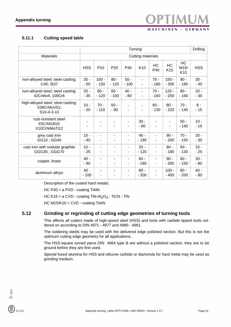
OPTIMUMM A S C H I N E N - G E R M A N Y
Appendix turning
© 2
012
GB
5.11.1 Cutting speed table
4.1.12
Turning Drilling
Materials Cutting materials
HSS P10 P20 P40 K10 HC P40
HCK15
HCM15/K10
HSS
non-alloyed steel; steel casting; C45; St37
35 -- 50
100 -- 150
80 -- 120
50 -- 100
--
70 -- 180
150 -- 300
90 -- 180
30 -- 40
non-alloyed steel; steel casting; 42CrMo4; 100Cr6
20 -- 35
80 -- 120
60 -- 100
40 -- 80
--
70 -- 160
120 -- 250
80 -- 160
20 -- 30
high-alloyed steel; steel casting;X38CrMoV51;
S10-4-3-10
10 -- 20
70 -- 110
50 -- 90
--
--
60 -- 130
80 -- 220
70 -- 140
8 - - 15
rust-resistant steel X5CrNi1810;
X10CrNiMoTi12
--
--
--
--
30 -- 80
--
--
50 -- 140
10 -- 15
grey cast ironGG10 ; GG40
15 -- 40
--
--
--
40 -- 190
--
90 -- 200
70 -- 150
20 -- 30
cast iron with nodular graphiteGGG35 ; GGG70
10 -- 25
--
--
--
25 -- 120
--
80 -- 180
60 -- 130
15 -- 25
copper, brass 40 -- 90
--
--
--
60 -- 180
--
90 -- 300
60 -- 150
30 -- 80
aluminum alloys 40 -- 100
--
--
--
80 -- 200
--
100 -- 400
80 -- 200
40 -- 80
Description of the coated hard metals:
HC P40 = a PVD - coating TiAlN
HC K15 = a CVD - coating TiN-Al2O3 - TiCN - TiN
HC M15/K10 = CVD - coating TiAiN
5.12 Grinding or regrinding of cutting edge geometries of turning tools
This affects all cutters made of high-speed steel (HSS) and tools with carbide tipped tools sol-dered on according to DIN 4971 - 4977 and 4980 - 4981.The soldering steels may be used with the delivered edge polished section. But this is not theoptimum cutting edge geometry for all applications.
The HSS-square turned piece DIN 4964 type B are without a polished section, they are to beground before they are first used.
Special fused alumina for HSS and silicone carbide or diamonds for hard metal may be used asgrinding medium.
Page 61Appendix turning Lathe OPTI D180 x 300 VARIO ; Version 1.3.7

Appendix turningOPTIMUMM A S C H I N E N - G E R M A N Y
5.12.1 Terms for the turning tool
Page 62
Illustr.5-44: Geometrically determined cutter for the separation process
Illustr.5-45: Cut and chip size
Illustr.5-46: Cut A - A, positive cutter Illustr.5-47: Cut A - A, negative cutter
Tool Wor
kpie
ce
Cutting direction
Wed
ge
Clearance surface
Chip thicknessChip surface
f
ε
ap χnχ
Chip surface
γPositive chip aangle β
αPositive clearance angle
Clearance surface
Chip surface
γNegative chip angle
β
αPositive clearance angle
Clearancesurface
Wedge angle β The following factors influence the chipbreak when turning
Chip angle γ Setting angle χ
Clearance angle α Corner radius r
Clearance angle minor cutting edge αn Cutting edge geometry
Setting angle χ Cutting speed Vc
Setting angle minor cutting edge χn Depth of cut ap
Point angle ε Infeed f
Depth of cut ap (mm)
Infeed f (mm/U)
© 2012
G
In most cases the setting angle is depending on the work piece. A setting angle of 45° to 75° issuitable for roughing. A setting angle of 90° to 95° (no tendency to chattering) is suitable forplaning.
The corner angle serves as passing from the major cutting edge to the minor cutting edge.Together with the infeed it determines the surface quality. The corner radius must not beselected too large as this might result in vibrations.
4.1.12Appendix turning Lathe OPTI D180 x 300 VARIO ; Version 1.3.7
B

OPTIMUMM A S C H I N E N - G E R M A N Y
Appendix turning
© 2
012
GB
5.12.2 Cutting edge geometry for turning tools
4.1.12
High-speed steel Hard metal
Clearance angle Chip angle Clearance
angle Chip angle
Steel +5° bis +7° +5° bis +6° +5° bis +11° +5° bis +7°
Cast non +5° bis +7° +5° bis +6° +5° bis +11° +5° bis +7°
NE - metal +5° bis +7° +6° bis +12° +5° bis +11° +5° bis +12°
Aluminum alloys +5° bis +7° +6° bis +24° +5° bis +11° +5° bis +24°
5.12.3 Types of cutting form levels
They are needed to influence the chip drain and the chip shape in order to achieve optimumchipping conditions.
Examples of types of cutting form levels
Illustr.5-48: cutting form level Illustr.5-49: cutting form level with fillet
b = 1,0mm to 2,2mm
t = 0,4mm to 0,5mm
b = 2,2mm with fillet
For infeeds of 0,05 to 0,5mm/U and depths of cut of 0,2mm to 3,0mm
The different apex angles of the cutting form level need to conduct the chip. ( j ) .
Illustr.5-50: Positive apex angle for planing Illustr.5-51: Neutral apex angle for planing and roughing
btγ γ
b
ϕ ϕ
Page 63Appendix turning Lathe OPTI D180 x 300 VARIO ; Version 1.3.7

Appendix turningOPTIMUMM A S C H I N E N - G E R M A N Y
Illustr.5-52: Negative apex angle for roughing
ϕ
Page 64
© 2012
G
The ready-ground major cutting edge must be slightly ground with a grindstone for the plan-ing.
For the roughing, a small chamfer must be produced with the grindstone in order to stabilizethe cutting edge against striking chips (bf = f x 0,8).
Illustr.5-53: Stabilize cutting edge
Polished section for recessing and cutting off
(for chip angle refer to table)
Illustr.5-54: Polished section recessing and cutting off
Polished section for threading
The point angle or the shape for chasing tools is depending on the type of thread.
Also refer to:
„Thread types“ on page 44 „Pitch angle“ on page 51
The measure X must be larger than the depth of thread. Make save that no chip angle is beingground as in this case there would be a strain of the profile.
bf
10°
α
γ1°1°
2°2°
4.1.12Appendix turning Lathe OPTI D180 x 300 VARIO ; Version 1.3.7
B

OPTIMUMM A S C H I N E N - G E R M A N Y
Appendix turning
© 2
012
GB
5.13 Lifetime and wear characteristics
Illustr.5-55: Polished section for threading
Xε
4.1.12
In the chipping shaping by lifetime we understand the time which the cutting edge survives(pure contact time).
The causes for the end of the lifetimes may be the following:
dimensional deviation too high cutting pressure bad surface quality high burr formation for tool exit
The wear of clearance surface VB and the creater wear on the chipping surface is the most com-mon type of tool wear. They are mainly formed by friction. The clearance surface wear haseffects on the dimensional accuracy of the workpieces and on the cutting force (the cutting forceincreases by 10% for each 0,1mm VB).
The clearance wear is generally used as lifetime criteria.
Crackings on the cutting edge may be caused by casting crusts or forgeing skins. Another causemay be ridge cracks (cracks transversal to the edge) which are caused by thermal and mechan-ical shock louds such as interrupted cuts or short contact times for very hard cutting materials.
The cutting edge crack may be caused by selecting a too rough cutting material or by wrongselection for cutting data.
If a thermal excessive strain of the cutting material is existing, there would be a plastic deforma-tion on the cutter.
Illustr.5-56: Clearance surface wear Illustr.5-57: Creater wear
VB
KB
KT
Page 65Appendix turning Lathe OPTI D180 x 300 VARIO ; Version 1.3.7

MaintenanceOPTIMUMM A S C H I N E N - G E R M A N Y
6 Maintenance
Page 66
In this chapter you will find important information about
inspectionmaintenancerepair
of the lathe.
ATTENTION!
Properly performed regular maintenance is an essential prerequisite for • safe operation,• faulty-free operation,• long service life of the lathe and• the quality of the products you manufacture.Installations and equipment from other manufacturers must also be in optimum condition.
6.1 Safety
WARNING!
The consequences of incorrect maintenance and repair work may include:• very serious injury to employees working on the lathe,• damage to the lathe.Only qualified employees should carry out maintenance and repair work on the lathe.
6.2 Inspection and maintenance
The type and extent of wear depends to a large extent on individual usage and service conditions. For this reason, all the intervals are only valid for the authorised conditions.© 2012
G
Interval Where? What? How?
Every week
Mac
hine
bed
Lubricate
• Lubricate all blank steel parts with a non-corrosive oil. „Operating material“ on page 16
Hea
dsto
ck Inspection• Control the tension of the synchronous belts.
( Illustr.4-9: „synchronous belt position change“ on page 33)
Lubricate • Slightly lubricate the change wheels and the leading spin-dle with a lithium grease.
4.1.12Maintenance Lathe OPTI D180 x 300 VARIO ; Version 1.3.7
B

OPTIMUMM A S C H I N E N - G E R M A N Y
Maintenance
© 2
012
GB
Every week
Lath
e sl
ide
Lubricate
• Lubricate the lubricating nipples on the lathe slide.
Illustr.6-1: Lathe slide
Semestrial
Hea
dsto
ck
Visual inspection
• Control if the synchronous belts are porous or worn.
As required
Top
slid
e
Readjust
• Readjust the guide clearance of the top slide.
Illustr.6-2: Lathe slide
As required
Com
poun
d sl
ide
Readjust
• Readjust the guide clearance of the compound slide.
Illustr.6-3: Lathe slide
Interval Where? What? How?
Lubricating nipples
Readjusting screws
Readjusting screws
4.1.12 Maintenance Lathe OPTI D180 x 300 VARIO ; Version 1.3.7
Page 67
MaintenanceOPTIMUMM A S C H I N E N - G E R M A N Y
As required
Spin
dle
nut o
f the
com
poun
d sl
ide
Readjust
• The set screw widens the flanks of screw thread of the spindle nut. If required, turn the set screw only slightly. A too widened set screw will lead to excessive wear.
Illustr.6-4: Lathe slide
As required
Lead
- scr
ew n
ut
Readjust
• The clearance of the lead-screw nut for opening and closing may be readjusted.
Illustr.6-5: Lathe slide
As required
Lead
- scr
ew n
ut
Readjust
• The locking split of the lead-screw nut may only be adjusted when it is closed. If the locking split is too small or too large this will lead to excessive wear.
Illustr.6-6: Lathe slide
Interval Where? What? How?
Fixture spindle nutSet screw
Readjusting screws
Adjusting screw
Page 68
© 2012
G
INFORMATION!
The work spindle bearing is prelubricated. It is not necessary to lubricate it again.
Maintenance Lathe OPTI D180 x 300 VARIO ; Version 1.3.7
4.1.12B

OPTIMUMM A S C H I N E N - G E R M A N Y
Maintenance
© 2
012
GB
6.3 Repair
4.1.12
For any repair work, get assistance from an employee of Optimum Maschinen GermanyGmbH’s technical service or send us the lathe.
If the repairs are carried out by qualified technical staff, then the instructions given in this manualmust be followed.
Optimum Maschinen Germany GmbH does not take responsibility nor does it guarantee againstdamage and operating abnomalies resulting from failure to observe this operating manual. Forrepairs only use faultless and suitable tools and original spare parts or parts from seriesexpressly authorised by Optimum Maschinen Germany GmbH.
Page 69Maintenance Lathe OPTI D180 x 300 VARIO ; Version 1.3.7

AbnomaltiesOPTIMUMM A S C H I N E N - G E R M A N Y
4.1.12Page 70 Abnomalties Lathe OPTI D180 x 300 VARIO ; Version 1.3.7
© 2012
GB
7 Abnomalties
7.1 Abnomalties in the lathe
Abnomalty Cause/possible effects Solution
Surface of workpiece too rough
• Tool blunt• Tool springs• Feed too high• Radius at the tool tip too small
• Resharpen tool • Clamp tool with less overhang• Reduce feed• Increase radius
Workpiece becomes coned
• Top slide is not exactly set to zero (when turning with the top slide)
• Set top slide to exact zero position
Lathe is chattering • Feed too high• Main bearings have clearance
• Reduce feed• Have the main bearings re-
adjusted
Center runs hot • Workpiece has expanded • Loosen tailstock center
Tool has a short edge life • Hard casting skin• Cutting speed to high• Crossfeed to high• Insufficient cooling
• First break casting skin • Reduce cutting speed• Lower crossfeed (smooth finish
allowance not over 0,5 mm)• More coolant
Flank wear too high • Clearance angle too small (tool "pushes")
• Tool tip not adjusted to center height
• Increase clearance angle• Correct height adjustment of the
tool
Cutting edge breaks off • Wedge angle too small (heat build-up)
• Grinding cracks due to wrong cool-ing
• Excessive clearance in the spin-dle bearing arrangement (vibra-tions)
• Increase wedge angle • Cool uniformly • Have the clearance in the spindle
bearing arrangement re-adjusted.
Cut thread is wrong • Tool is clamped incorrectly or has been started grinding the wrong way
• Wrong pitch• Wrong diameter
• Adjust tool to the center• Grind angle correctly• Adjust right pitch• Turn the workpiece to the correct
diameter

OPTIMUMM A S C H I N E N - G E R M A N Y
Ersatzteile - Spare parts - D180x300 Vario
8 Ersatzteile - Spare parts - D180x300 Vario
8.1 Ersatzteilzeichnung Antrieb - Drawing spare parts drive
Abb.8-1: Antrieb - Drive
4.01.12
Y:\Betriebsanleitungen\lathes\D180x300\D180x300_parts\D180x300_parts.fm
71

Ersatzteile - Spare parts - D180x300 VarioOPTIMUMM A S C H I N E N - G E R M A N Y
8.2 Ersatzteilzeichnung Oberschlitten und Planschlitten - Drawing spare parts top slide and cross slide
72
Y:\Betriebsanleitunge
Abb.8-2: Oberschlitten und Planschlitten - Top slide and cross slide
n\lathes\D180x300\D180x300_parts\D180x300_parts.fm
4.01.12

OPTIMUMM A S C H I N E N - G E R M A N Y
Ersatzteile - Spare parts - D180x300 Vario
8.3 Ersatzteilzeichnung Bettschlitten - Drawing spare parts lathe saddle
Abb.8-3: Bettschlitten - Lathe saddle
4.01.12
Y:\Betriebsanleitungen\lathes\D180x300\D180x300_parts\D180x300_parts.fm
73

Ersatzteile - Spare parts - D180x300 VarioOPTIMUMM A S C H I N E N - G E R M A N Y
8.4 Ersatzteilzeichnung Maschinenbett - Drawing spare parts lathe bed
Abb.8-4: Maschinenbett - Lathe bed
74
Y:\Betriebsanleitungen\lathes\D180x300\D180x300_parts\D180x300_parts.fm
4.01.12

OPTIMUMM A S C H I N E N - G E R M A N Y
Ersatzteile - Spare parts - D180x300 Vario
8.5 Ersatzteilzeichnung Reitstock - Drawing spare parts teilstock
Abb.8-5: Reitstock - Teilstock
4.01.12
Y:\Betriebsanleitung
en\lathes\D180x300\D180x300_parts\D180x300_parts.fm75

Ersatzteile - Spare parts - D180x300 VarioOPTIMUMM A S C H I N E N - G E R M A N Y
8.6 Ersatzteilzeichnung Zubehör - Drawing spare parts accessory
Abb.8-6: Vorderansicht - Front view
Abb.8-7: Hinteransicht - Back view
76
Y:\Betriebsanleitungen\lathes\D180x300\D180x300_parts\D180x300_parts.fm
4.01.12

OPTIMUMM A S C H I N E N - G E R M A N Y
Ersatzteile - Spare parts - D180x300 Vario
8.7 Schaltplan - Wiring diagram
Abb.8-8: Schaltplan - Wiring diagram
4.01.12
Y:\Betriebsanleitungen\lathes\D180x300\D180x300_parts\D180x300_parts.fm
77

Ersatzteile - Spare parts - D180x300 VarioOPTIMUMM A S C H I N E N - G E R M A N Y
8.8 Maschinenschilder - Machine labels
Abb.8-9: Maschinenschilder - Machine labels
8.8.1 Maschinenschilder - Machine labels
Pos. Bezeichnung Designation
Menge Grösse ArtikelnummerQuan-
tity Size Article no.1 Frontschild Front label 1 03420301L012 Sicherheitsschild Safety label 1 03420301L023 Sicherheitsschild Safety label 1 03420301L034 Hinweisschild Instruction label 1 03420301L045 Maschinenschild Machine label 1 03420301L056 Schild Drehzahlanzeige Rotation speed indicator 1 03420301L06
78
Y:\Betriebsanleitunge
n\lathes\D180x300\D180x300_parts\D180x300_parts.fm4.01.12
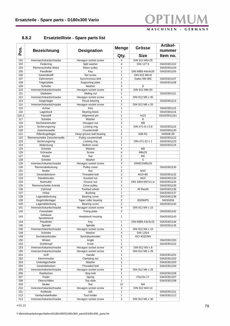
OPTIMUMM A S C H I N E N - G E R M A N Y
Ersatzteile - Spare parts - D180x300 Vario
8.8.2 Ersatzteilliste - Spare parts list
Pos. Bezeichnung Designation Menge Grösse Artikel-
nummerQty. Size Item no.
101 Innensechskantschraube Hexagon socket screw 4 DIN 912 M5×25102 Federring Split washer 4 DIN 127 5 03420301102104 Riemenscheibe Motor Motor pulley 1 03420301104105 Passfeder Key 1 DIN 6885-A4x4x20 03420301105106 Gewindestift Set screw 1 DIN 915 M6×8107 Zahnriemen Synchronous belt 2 Gates 5M-365 03420301107108 Trägerplatte Supporting plate 1 03420301108109 Scheibe Washer 3 8110 Innensechskantschraube Hexagon socket screw 3 DIN 912 M8×20111 Gleitstein Sliding nut 1 03420301111112 Innensechskantschraube Hexagon socket screw 1 DIN 912 M6 x 30113 Gegenlager Thrust bearing 1 03420301113114 Innensechskantschraube Hexagon socket screw 2 DIN 912 M6 x 20115 Achse Axis 1 03420301115116 Lagerbock Bearing block 1 03420301116
116-1 Passstift Alignment pin 1 4x22 034203011161117 Scheibe Washer 1 8118 Sechskantmutter Hexagon nut 3 M8119 Sicherungsring Locking ring 1 DIN 471-8 x 0.8 03420301119120 Zwischenwelle Countershaft 1 03420301120121 Rillenkugellager Deep groove ball bearing 2 608-RZ 040608.2R122 Riemenscheibe Zwischenwelle Pulley countershaft 1 03420301122123 Sicherungsring Locking ring 1 DIN 471-22 x 1 03420301123124 Abdeckung Bottom cover 1 03420301124125 Scheibe Washer 4 M8126 Schraube Screw 4 M8x25127 Mutter Nut 2 M5128 Scheibe Washer 2 5129 Innensechskantschraube Hexagon socket screw 2 DIN912/M5x25130 Riemenabdeckung Pulley cover 1 03420301130131 Mutter Nut 2 M10132 Gewindebolzen Threaded bolt 2 M10×80 03420301132133 Rändelmutter Knurled nut 2 M10 03420301133134 Nutmutter Groove nut 2 DIN 1804-M27x1-w 03420301134135 Riemenscheibe Antrieb Drive pulley 1 03420301135136 Zahnrad Toothed wheel 1 40 theeth 03420301136137 Hülse Bushing 1 03420301137138 Lagerabdeckung Bearing cover 2 03420301138139 Kegelrollenlager Taper roller bearing 2 30206/P5 04030206140 Lagerabdeckung Bearing cover 2 03420301140141 Innensechskantschraube Hexagon socket screw 4 DIN 912 M4 x 10142 Fixierplatte Fixing plate 2 03420301142
143 Gehäuse Spindelstock Headstock housing 1 03420301143
144 Passfeder Key 1 DIN 6885-A3x3x15 03420301144145 Spindel Spindle 1 03420301145146 Innensechskantschraube Hexagon socket screw 1 DIN 912 M4 x 10148 Scheibe Washer 4 DIN 125/4149 Sechskantmutter Sechskantmutter 2 ISO 4032/M4150 Winkel Angle 1 03420301150152 Drehknopf Knob 1 03420301152153 Innensechskantschraube Hexagon socket screw 6 DIN 912 M3 x 8155 Innensechskantschraube Hexagon socket screw 1 DIN 912 M5 x 25201 Griff Handle 1 03420301201202 Klemmmutter Clamping nut 1 03420301202203 Unterlagscheibe Washer 1 03420301203204 Gewindebolzen Threaded bolt 1 03420301204205 Innensechskantschraube Hexagon socket screw 8 DIN 912 M6 x 25206 Rastbolzen Stop bolt 1 03420301206207 Feder Spring 1 ∅5x10x ∅1 03420301207208 Oberschlitten Top slide 1 03420301208209 Mutter Nut 12 M4210 Innensechskantschraube Hexagon socket screw 3 DIN 912 M4×14211 Keilleiste Gib 1 03420301211212 Vierfachstahlhalter Tool holder 1 03420301212213 Innensechskantschraube Hexagon socket screw 2 DIN 912 M5 x 30
4.01.12
Y:\Betriebsanleitungen\lathes\D180x300\D180x300_parts\D180x300_parts.fm
79

Ersatzteile - Spare parts - D180x300 VarioOPTIMUMM A S C H I N E N - G E R M A N Y
214 Schwalbenschwanzführung Dovetail guide 1 03420301214215 Drehring Swivel 1 03420301215216 Spindel Spindle 1 03420301216217 Spannstift Dowel pin 2 3x12 03420301217218 Lagerbock Bearing block 1 03420301218219 Innensechskantschraube Hexagon socket screw 2 DIN 912 M5 x 12220 Skalenring Scale ring 1 03420301220221 Gewindestift Set screw 2 DIN 915 M6 x 6222 Stift Pin 2 03420301222223 Federblech Spring steel sheet 2 03420301223224 Führungsscheibe Guiding disk 2 03420301224225 Hebel Lever 1 03420301225226 Griffhülse Handle 2 03420301226227 Befestigungsschraube Fixing screw 2 03420301227228 Innensechskantschraube Hexagon socket screw 1 DIN 912 M4×8229 Gewindestift Set screw 1 DIN 914 M5 x 10230 Hülse Bushing 1 03420301230231 Öler Oiler 6 D=6mm 03420301231232 Innensechskantschraube Hexagon socket screw 3 DIN 912 M4×20233 Kelleiste Gib 1 03420301233234 Linsenkopfschraube Tallow-drop screw 8 M3 x 8235 Halter Abstreifer Holder stripper 2 03420301235236 Abstreifer Stripper 2 03420301236238 Innensechskantschraube Hexagon socket screw 6 DIN 912 M5×10239 Befestigungsschiene Fastening gib 1 03420301239240 Innensechskantschraube Hexagon socket screw 6 M4 x 10241 Spindelmutter Spindle nut 1 03420301241242 Spindel Spindle 1 03420301242243 Hebel Lever 1 03420301243244 Führungsscheibe Guide disk 1 03420301244245 Skalenring Scale ring 1 03420301245246 Innensechskantschraube Hexagon socket screw 2 DIN 912 M6×50247 Lagerbock Bearing block 1 03420301247249 Innensechskantschraube Hexagon socket screw 1 DIN 912 M8×25250 Befestigungsschiene Fixing gib 1 03420301250251 Abstreifer Stripper 2 03420301251252 Halter Abstreifer Holder stripper 2 03420301252254 Planschlitten Cross slide 1 03420301254
254-1 Skala Scale 1 034203012541255 Bettschlitten Bed slide 1 03420301255256 Bügel Holder 1 03420301256257 Innensechskantschraube Hexagonal socket screw 2 GB70-85/M4x10258 Schraube Screw 2 M5x10259 Welle Shaft 1 03420301259260 Sechskantmutter Hexagonal nut 1 GB6170-86/M3261 Innensechskantschraube Hexagonal socket screw 1 GB70-85/M3x10262 Sechskanthülse Hexagonal case 1 03420301262263 Scheibe Washer 2 GB77.1-85/3264 Innensechskantschraube Hexagonal socket screw 2 GB70-85/M3x6265 Späneschutzschild Splinter shield 1 03420301265301 Gewindestift Set screw 1 DIN 9124 M8 x 8302 Befestigungsmutter Handrad Fixing nut handwheel 1 M8 H=16mm303 Handrad Handwheel 1 03420301303304 Federblech Spring steel sheet 1 03420301304305 Innensechskantschraube Hexagon socket screw 2 DIN 914 M5×10306 Skalenring Scale ring 1 03420301306307 Gleitlagerung Track bed shaft 1 03420301307308 Innensechskantschraube Hexagon socket screw 2 DIN 912 M8×25309 Gewindestift Set screw 1 DIN 914 M5×8310 Schlosskasten Apron 1 03420301310311 Passfeder Key 1 DIN 6885-A3x3x8 03420301311312 Zahnwelle Gear shaft 1 14 theeth, module 1 03420301312313 Welle Shaft 1 03420301313
314 Zahnradkombination Gear combination 1 44/21 theeth, module 1 / 1,25 03420301314
315 Gewindestift Set screw 1 DIN 914 M4×35316 Mutter Nut 1 M4317 Schlossmutter Apron nut 1 03420301317
Pos. Bezeichnung Designation Menge Grösse Artikel-
nummerQty. Size Item no.
80
Y:\Betriebsanleitungen\lathes\D180x300\D180x300_parts\D180x300_parts.fm
4.01.12

OPTIMUMM A S C H I N E N - G E R M A N Y
Ersatzteile - Spare parts - D180x300 Vario
318 Passstift Alignment pin 2 ∅4 x 10319 Innensechskantschraube Hexagon socket screw 2 DIN 912 M4×10320 Nachstellleiste Gib 1 03420301320321 Gewindestift Set screw 1 DIN 913 M6×8
322 Feder Spring 1 ∅0.6×∅3.5×12 03420301322
323 Stahlkugel Steel ball 1 ∅ 4.5 03420301323324 Innensechskantschraube Hexagon socket screw 4 DIN 912 M4×12325 Mutter Nut 4 M4326 Welle Shaft 1 03420301326327 Spannstift Dowel pin 1 DIN 1481 3×30 03420301327328 Drehknopf Turning knob 1 03420301328329 Gewindestift Set screw 1 DIN 914 M5×6330 Einrückhebel Engaging lever 1 03420301330331 Schraube Screw 1 03420301331332 Hülse Sleeve 1 03420301332333 Welle Shaft 1 03420301333334 Sicherungsring Retaining ring 1 03420301334335 Scheibe Washer 1 03420301335336 Rastblech Locking plate 1 03420301336401 Sicherungsscheibe Locking wahser 2 03420301401402 Zahnrad Gear 1 60 theeth 03420301402403 Zahnrad Gear 1 20 theeth 03420301403404 Hülse Bushing 2 03420301404405 Achswelle Axle shaft 2 03420301405406 Nutenstein Nut stone 2 M8 03420301406407 Zahnrad Gear 1 24 theeth 03420301407408 Zahnrad Gear 2 80 theeth 03420301408409 Mutter Nut 1 M10410 Scheibe Disk 1 10411 Hülse Bushing 1 03420301411412 Wechselradschere Change gear shear 1 03420301412413 Innensechskantschraube Hexagon socket screw 1 DIN 912 M6×35414 Gleitlager Slide bearing 1 03420301414415 Lagerbock Bearing block 1 03420301415416 Schraube Screw 4 M6×14417 Passfeder Key 1 DIN 6885-A3x3x16 03420301417418 Leitspindel Leadscrew 1 03420301418419 Maschinenbett Bed 1 03420301419420 Innensechskantschraube Hexagon socket screw 5 DIN 912 M4×12421 Zahnstange Rack 1 03420301421422 Axial- Rillenkugellager Axial deep groove ball bearing 2 51100 04051100423 Lagerbock Bearing block 1 03420301423424 Befestigungsmutter Fixing nut 1 03420301424425 Stellschraube, Gewindestift Adjusting screw set screw 1 DIN 915 M8×6426 Schutzabdeckung Protective cover 1 03420301426427 Innensechskantschraube Hexagon socket screw 2 DIN 912 M4×10428 Zahnrad Gear 1 25 theeth 03420301428429 Zahnrad Gear 1 30 theeth 03420301429430 Zahnrad Gear 1 33 theeth 03420301430431 Zahnrad Gear 1 35 theeth 03420301431432 Zahnrad Gear 1 40 theeth 03420301432433 Zahnrad Gear 1 45 theeth 03420301433434 Zahnrad Gear 1 50 theeth 03420301434435 Zahnrad Gear 1 52 theeth 03420301435436 Zahnrad Gear 1 66 theeth 03420301436501 Klemmhebel Clamping lever 1 03420301501502 Klemmschraube Clamping screw 1 03420301502503 Klemmhülse Clamping bushing 1 03420301503504 Reitstockpinole Pinole 1 03420301504505 Reitstockgehäuse Tailstock housing 1 03420301505506 Reitstockspindel Tailstock spindle 1 03420301506507 Passfeder Key 1 DIN 6885-A3x3x8 03420301507508 Mutter Nut 1 M6509 Gewindestift Set screw 1 DIN 915 M6×14
510 Axial-Rillenkugellager Axial deep groove ball bearing 1 51100 04051100
511 Lagerbock Bearing block 1 03420301511
Pos. Bezeichnung Designation Menge Grösse Artikel-
nummerQty. Size Item no.
4.01.12
Y:\Betriebsanleitungen\lathes\D180x300\D180x300_parts\D180x300_parts.fm
81

Ersatzteile - Spare parts - D180x300 VarioOPTIMUMM A S C H I N E N - G E R M A N Y
512 Skalenring Scale ring 1 03420301512513 Federblech Spring steel sheet 1 03420301513514 Handrad Handwheel 1 03420301514515 Befestigungsmutter Fixing nut 1 M8 H=16mm516 Gewindestift Set screw 1 DIN 914 M8 x 6517 Befestigungsschraube Fixing screw 1 03420301517518 Griff Grip 1 03420301518519 Innensechskantschraube Hexagon socket screw 5 DIN 912 M5×12520 Anschlag Stop 1 03420301520521 Gewindestift Set screw 2 DIN 915 M6×12522 Reitstock Unterteil Tailstock bottom part 1 03420301522523 Feder Spring 1 1×12×L 03420301523524 Klemmplatte Clamping plate 1 03420301524525 Sechskantschraube Hexagon screw 1 DIN 931 M10×70526 Gewindestift Set screw 2 DIN 915 M6×16527 Scheibe Washer 1 10528 Mutter Nut 1 M10529 Mitlaufende Körnerspitze Revolving centre 1 03420301529530 Spänewanne Chip tray 1 03420301997534 Gummiablage/ Werkzeug Rubber place for tools 1 03420301631535 Sicherungsgehäuse Fuse housing 2 03420301535536 Innensechskantschraube Hexagon socket screw 4 DIN 912 M4×45537 Abdeckung Cover 1 03420301537540 Drehfutterschutz Protection lathe chuck 1 0342030100541 Dreibackenfutter 3-jaw chuck 1 03420301639542 Spritzwand Rear splash guard 1 03420301998545 Abdeckung Cover 1 03420301545548 Halter Holder 1 03420301548549 E-Box E-Box 1 03420301549550 Skala oben Scale top 03420301550551 Skala unten Scale below 03420301551
Ersatzteilliste Elektrik/ Spare parts electrical1A1 Drehzahlanzeige Rotation speed indicator 1 030202451671A2 Drehzahlsensor Rotation speed sensor 1 033381202791S1 Not-Aus-Schalter Emergency stop button 1 03338120S1.21S4 Schalter Abdeckung Cover safety switch 1 04600151S5 Drehfutterschutz Protector chuck safety switch 1 04600151S6 Ein-Aus-Taster On-off switch 1 03338120S1.31S8 Hauptschalter Maim switch 1 03338120S1.11S9 Drehrichtungschalter Change-over switch 1 0460009Q1,6 Steuerplatine Control board 1 03338120Q1.6Q1,6 Steuerplatine Control board 1 03338120Q1.71R1 Potentiometer Potentiometer 1 03338120R1.51F1/1F2 Sicherung Fuse 2 034203011F1
LF Netzfilter Line filter 1 03420301LF1M1 Motor Motor 1 03420301103
03420301M1Teile ohne Abbildung - Parts without illustration
Drehfutterschlüssel Key for lathe chucks 1 0340200Zubehör kplt. Accessory box cpl. 1 03420301000
Oberschlitten kplt. Top slide cpl. 1 03420301999Wechselradsatz kplt. Change gear set cpl. 1 03420301437
Reitstock kplt. Tailstock cpl. 1 03420301996
Pos. Bezeichnung Designation Menge Grösse Artikel-
nummerQty. Size Item no.
82
Y:\Betriebsanleitunge
n\lathes\D180x300\D180x300_parts\D180x300_parts.fm4.01.12

OPTIMUMM A S C H I N E N - G E R M A N Y
Appendix
© 2
012
GB
9 Appendix
9.1 Copyright
4.1.12
© 2012
This document is copyright. All derived rights are also reserved, especially those of translation,re-printing, use of figures, broadcast, reproduction by photo-mechanical or similar means andrecording in data processing systems, whether partial or total.
The company reserves the right to make technical alterations without prior notice.
9.2 Terminology/Glossary
Term Explanation
Headstock Housing for the feed gear and the syn-chronous belt pulleys.
Lathe chuck Clamping tool for holding the workpiece.
Drill chuck Device for holding the bit
Lathe saddle Slide on the slideway of the machine bed which feeds parallel to the tool axis.
Cross slide Slide on the lathe saddle which moves transversely to the tool axis.
Top slide Swivelling slide on the cross slide.
Taper mandrel Taper of the bid, the drill chuck or the center.
Tool Cutting tool, bit, etc.
Workpiece Piece to be turned or machined.
Tailstock Movable turning aid.
Rest Follow or steady support for turning long workpieces.
Lathe dog Device or clamping aid for driving pieces to be turned between centers.
Page 83Appendix Lathe OPTI D180 x 300 VARIO ; Version 1.3.7

AppendixOPTIMUMM A S C H I N E N - G E R M A N Y
9.3 Liability claims for defects / warranty
Page 84
Beside the legal liability claims for defects of the customer towards the seller the manufacturerof the product, OPTIMUM GmbH, Robert-Pfleger-Straße 26, D-96103 Hallstadt, does not grantany further warranties unless they are listed below or had been promised in the frame of a singlecontractual agreement.
The processing of the liability claims or of the warranty is performed as chosen by OPTIMUM GmbH either directly or through one of its dealers. Any defective products or components of such products will either be repaired or replaced by components which are free from defects. The property of replaced products or components passes on to OPTIMUM GmbH.The automatically generated original proof of purchase which shows the date of purchase, the type of machine and the serial number, if applicable, is the precondition in order to assert liability or warranty claims. If the original proof of purchase is not presented, we are not able to perform any services.Defects resulting of the following circumstances are excluded from liability and warranty claims:- Using the product beyond the technical options and proper use, in particular due to over-
straining of the machine- Any defects arising by one's own fault due to faulty operations or if the operating manual
is disregarded- Inattentive or incorrect handling and use of improper equipment- Non-authorized modifications and repairs- Insufficient installation and safeguarding of the machine- Disregarding the installation requirements and conditions of use- Atmospheric discharges, overvoltage and lightning strokes as well as chemical influencesThe following items are as well not subject to the liability or warranty claims:- Wearing parts and components which are subject to a standard wear as intended such as
e.g. V-belts, ball bearings, illuminants, filters, sealings, etc.- Non reproducible software errorsAny services which OPTIMUM GmbH or one of its agents performs in order to fulfill in the frame of an additional guarantee are neither an acceptance of the defects nor an accept-ance of its obligation to compensate. Such services do neither delay nor interrupt the war-ranty period.Place of jurisdiction among traders is Bamberg.If one of the above mentioned agreements is totally or partially inefficient and/or null, it is considered as agreed what is closest to the will of the warrantor and which remains in the framework of the limits of liability and warranty which are predefined by this contract.
9.4 Note regarding disposal / options to reuse:
© 2012
G
Please dispose of your device environmentally friendly by disposing of scrap in a professionalway.
Please neither throw away the packaging nor the used machine later on, but dispose of themaccording to the guidelines established by your city council/municipality or by the correspondingwaste management enterprise.
4.1.12Appendix Lathe OPTI D180 x 300 VARIO ; Version 1.3.7
B

OPTIMUMM A S C H I N E N - G E R M A N Y
Appendix
© 2
012
GB
9.4.1 Decommissioning
4.1.12
CAUTIONUsed devices need to be decommissioned in a professional way in order to avoid later misuses and endangerment of the environment or persons• Pull off the mains plug.• Disconnect the connection cable.• Remove all environmentally hazardous operating fluids from the used device.• If applicable remove batteries and accumulators.• Disassemble the machine if required into easy-to-handle and reusable
assemblies and component parts.• Supply the machine components and operating fluids to the provided disposal routes.
9.4.2 Disposal of the packaging of new devices
All used packaging materials and packaging aids of the machine are recyclable and generallyneed to be supplied to the material reuse.
The packaging wood can be supplied to the disposal or the reuse.
Any packaging components made of cardboard box can be chopped up and supplied to thewaste paper collection.
The films are made of polyethylene (PE) and the cushion parts are made of polystyrene (PS).These materials can be reused after reconditioning if they are forwarded to a collection stationor to the appropriate waste management enterprise.
Only forward the packaging materials correctly sorted to allow a direct reuse.
9.4.3 Disposing of the old device
INFORMATION
Please make sure in your own interest and in the interest of the environment that all componentparts of the machine will be disposed of in the provided and admitted ways.
Please note that the electrical devices include lots of reusable materials as well as environmen-tally hazardous components. Account for separate and professional disposal of the componentparts. In case of doubt, please contact your municipal waste management. If appropriate, call onthe help of a specialist waste disposal company for the treatment of the material.
9.4.4 Disposal of electrical and electronic components
Please make sure that electrical components are disposed of in a professional way according tothe legal requirements.
The device includes electric and electronic components and must not be disposed of with therubbish. According to the European directive 2002/96/EG regarding electrical and electronicused devices and the execution of national rights used electrical tools and electrical machinesneed to be collected separately and be supplied to an environmentally compatible reuse.
Being the machine operator you should obtain information regarding the authorized collection ordisposal system which applies for your company.
Please make sure that the batteries and/or accumulators are disposed of in a professional wayaccording to the legal regulations. Please only throw discharged batteries in the collection boxesin shops or at municipal waste management companies.
Page 85Appendix Lathe OPTI D180 x 300 VARIO ; Version 1.3.7

AppendixOPTIMUMM A S C H I N E N - G E R M A N Y
9.4.5 Disposal of lubricants and coolants
Page 86
ATTENTION
Please imperatively make sure to dispose of the used coolant and lubricants in an envi-ronmentally compatible way. Observe the disposal notes of your municipal waste man-agement companies.
INFORMATIONUsed coolant emulsions and oils should not be mixed up since it is only possible to reuse usedoils which had not been mixed up without pre-treatment.
The disposal notes for the used lubricants are made available by the manufacturer of the lubri-cants. If necessary, request the product-specific data sheets.
9.5 Disposal
Disposal of used electric and electronic machines(Applicable in the countries of the European Union and other European countries with a sepa-rate collecting system for those devices).The sign on the product or on its packing indicates that the product must not be handles as com-mon household waist, but that is needs to be delivered to a central collection point for recycling.Your contribution to the correct disposal of this product will protect the environment and thehealth of your fellow men. The environment and the health are endangered by incorrect dis-posal. Recycling of material will help to reduce the consumption of raw materials. Your DistrictOffice, the municipal waste collection station or the shop where you have bought the product willinform you about the recycling of this product.
9.6 RoHS , 2002/95/CE
© 2012
G
The sign on the product or on its packing indicates that this product complies with the Europeanguideline 2002/95/EC .
4.1.12Appendix Lathe OPTI D180 x 300 VARIO ; Version 1.3.7
B

OPTIMUMM A S C H I N E N - G E R M A N Y
Appendix
© 2
012
GB
9.7 Product follow-up
4.1.12
We are required to perform a follow-up service for our products which extends beyond shipment.
We would be grateful if you could send us the following information:
Modified settingsAny experiences with the lathe which might be important for other usersRecurring failures
Optimum Maschinen Germany GmbHDr.-Robert-Pfleger-Str. 26
D-96103 Hallstadt
Fax +49 (0) 951 - 96 555 - 888E-Mail: [email protected]
Page 87Appendix Lathe OPTI D180 x 300 VARIO ; Version 1.3.7

OPTIMUMM A S C H I N E N - G E R M A N Y
9.8 EC Declaration of Conformity
Page 88
© 2012
G
The manufacturer /retailer:
Optimum Maschinen Germany GmbHDr.-Robert-Pfleger-Str. 26D - 96103 Hallstadt
hereby declares that the following product,
Type of machine: OPTI D180 x 300 VARIO
Designation of the machine:
Lathe
Serial number: _ __ __ __ __
Year of manufacture: 20__
all relevant provisions of the Machinery Directive (2006/42/EC) corresponds.
The machnine continues to comply with all provisions of the Directives Electrical equipment(2006/95/EC) and electromagnetic compatibility (2004/108/EC).
The following harmonized standards were applied:
DIN EN 12100-1:2003/A1:2009
Safety of machinery - Basic concepts, general principles for design -Part 1: Basic terminology, methodology
DIN EN 12100-2:2003/A1:2009
Safety of machinery - Basic concepts, general principles for design -Part 2: Technical principles
DIN EN 60204-1 Safety of machinery - Electrical equipment of machines - Generalrequirements
The following technical standards were applied:
DIN EN 12840: 06/2001
Safety of machine tools - Manually controlled turning machines with or without automatic control.
Responsible for documentation: Kilian Stürmer, Tel.: +49 (0) 951 96822-0
Address: Dr.-Robert-Pfleger-Str. 26D - 96103 Hallstadt
Hallstadt, 4/January/2012
Kilian Stürmer(Manager)
4 / 01 / 09Appendix Lathe OPTI D180 x 300 VARIO ; Version 1.3.7
B

OPTIMUMM A S C H I N E N - G E R M A N Y
Index
4.1.12 Page 89Index Lathe OPTI D180 x 300 VARIO ; Version 1.3.7
© 2
012
GB
10 Index
AAccessory ......................................................23Adjusting
feeds and thread pitches .........................34BBediensymbole ..............................................26British threads ................................................49CCleaning .........................................................22Cones ............................................................56Cutter .............................................................40Cutting material ..............................................59Cutting off ......................................................54Cutting speed .................................................60Cutting speed table ........................................61DDimensions ....................................................16EEC Declaration of Conformity ........................88Environmental conditions ...............................16External threads, Internal threads ..................43FFeeds .............................................................34GGreasing ........................................................22Grinding of cutting edge geometries ..............61HHead spindle seat ..........................................29IInstallation ......................................................21MMachine data .................................................16
Dimensions ..............................................16Mechanical maintenance work ......................15Metric thread ..................................................47OOptional accessory ........................................23Outside machining .........................................42PProper use .......................................................7RReasonably foreseeable misuse ......................8Recessing ......................................................54SSafety
warning notes ............................................6TTechnical data
Environmental conditions ........................16Machine data ...........................................16
Thread pitches ...............................................34
Thread types ..................................................44Transport .......................................................19Turning ..........................................................37Turning cones ................................................56Turning off .....................................................54Turning short tapers
with the tailstock ......................................34UUsing lifting equipment ..................................15WWarming up the machine ...............................22