operation & maintenance vaxicool mobile refrigerator/freezer
TRANSCRIPT

OPERATION & MAINTENANCE
VaxiCool® Mobile Refrigerator/Freezer
An Advanced Technology Vaccine Storage & Transport System
Model VXC-2
2900 Dryden Road
Dayton, Ohio 45439 U.S.A.
Telephone: (937) 312-0114
Fax: (937) 312-1277
Email: [email protected]
www.acutemp.com

VXC-2 Operations Manual June 2006 AcuTemp www.acutemp.com
2 rev. 4
Do not turn on the VaxiCool if you have not read the entire user’s manual. Failure
to understand the meaning of the light emitting diode (LED) indicators and the
liquid crystal display (LCD) readouts could result in loss of your valuable vaccines
and/or biologicals and, possibly, in damage to the unit.
This manual is for the current model and month of manufacture. If you need instructions
for a different unit please consult the manufacturer for assistance. Contact
[email protected] or telephone 937-312-0114 and ask for technical support.

VXC-2 Operations Manual June 2006 AcuTemp www.acutemp.com
3 rev. 4
CAUTIONS IF DAMAGE OCCURS TO THE UNIT, THE UNIT MUST BE REPAIRED AT THE FACTORY AT THE EXPENSE OF THE END USER. SEE WARRANTY SECTION. • USE THE –22°C TEMPERATURE SETTING ONLY FOR MATERIALS
THAT MUST BE STORED FROZEN.
• DO NOT LOSE OR MISPLACE FREEZER KEYS SUPPLIED WITH THE UNIT. REPLACEMENT MAY NOT BE AVAILABLE AND FACTORY REPAIR WILL BE REQUIRED.
• DO NOT TILT THE UNIT OVER 30° WHILE OPERATING AND FOR
MAXIMUM EFFICIENCY DO NOT TILT THE UNIT DURING OPERATION.
• DO NOT STORE THE UNIT IN TEMPERATURES BELOW –20°C (-4°F)
OR OVER 60°C (140°F).
• DO NOT OPERATE THE UNIT IN AMBIENT TEMPERATURES BELOW 5°C (41°F) OR ABOVE 30°C (86°F).
• DO NOT SIT OR STAND ON THE UNIT. • DO NOT PLACE ANY OBJECT WEIGHING OVER 10 LBS ON THE LID. • DO NOT SUBMERGE THE UNIT IN WATER. • DO NOT STACK THE UNIT UNLESS BOXED.
• USE THE +4°C TEMPERATURE SETTING ONLY WITH MATERIALS
THAT MUST BE STORED ABOVE FREEZING.

VXC-2 Operations Manual June 2006 AcuTemp www.acutemp.com
4 rev. 4
TABLE OF CONTENTS Subject Page Introduction 5
General Description 5
Starting the VaxiCool 6
VaxiCool Display and Alarm Functions 11
Maintenance 16
Warranty 19
Appendix A – Solar Panel Application 20
VXC-2 Operations Manual June 2006 AcuTemp www.acutemp.com
5 rev. 4
INTRODUCTION This manual is written to enable the VaxiCool user to readily start and operate the unit in
the freezer mode, understand the light emitting diode (LED) and liquid crystal display
(LCD) readouts, and perform rudimentary repairs and adjustments. Any questions about
the unit should be directed to Energy Storage Technologies, Inc. by telephone, fax, or
email. Please see the front cover for contact information.
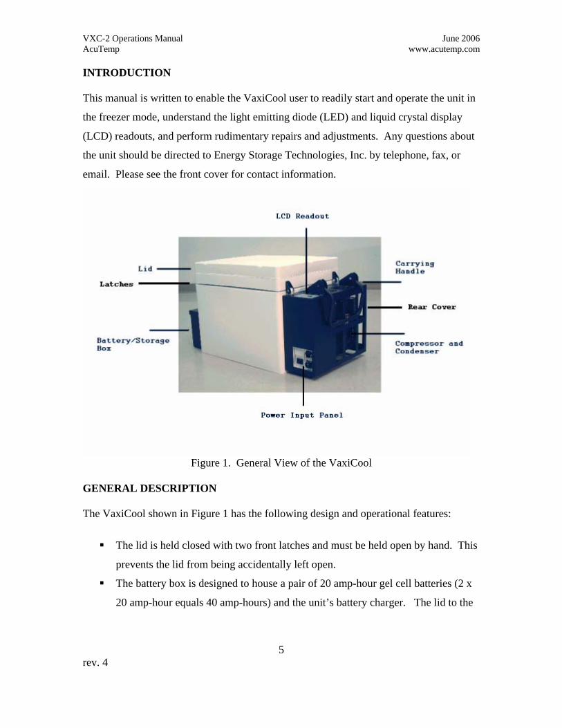
Figure 1. General View of the VaxiCool
GENERAL DESCRIPTION The VaxiCool shown in Figure 1 has the following design and operational features:
The lid is held closed with two front latches and must be held open by hand. This
prevents the lid from being accidentally left open.
The battery box is designed to house a pair of 20 amp-hour gel cell batteries (2 x
20 amp-hour equals 40 amp-hours) and the unit’s battery charger. The lid to the
VXC-2 Operations Manual June 2006 AcuTemp www.acutemp.com
6 rev. 4
box may be opened after removing the two screws keeping it closed. The battery
charger for the unit is located under the lid of the battery box.
The power input panel has three different connectors (See Figure 4.):
− One for conventional AC power, either 120 VAC or 240 VAC (90 – 260
VAC),
− One for a solar panel or PV/AUX power source, and
− One for an external 12 Volt DC battery.
A key switch located on the power input panel allows the user to change from the
–22°C freezer mode to the +4°C cooler mode.
The cover on the back of the unit protects:
− The compressor and condenser of the refrigeration system.
− The electronic components and their associated electrical leads. These
components include: the power board, the AC to DC power supply, the
compressor oscillator drive board, and the control board with LCD
readout.
Ergonomically designed handles for easy transport of the unit are located on both
the front and back of the unit. These handles can be used by either two or four
people to maintain the unit on the level while moving it in the field.
The payload space/volume is approximately 27 liters. The unit weighs about 90 lbs
without the gel cell batteries. It weighs approximately 125 lbs with the two 20 amp-hour
gel cell batteries.
STARTING THE VAXICOOL
The VaxiCool may be started by connecting the unit to an appropriate power source with
power ranges as defined by this manual. If a solar panel is used, proper sunlight is
required. The unit requires battery backup if the sunlight is not sufficiently intense.

VXC-2 Operations Manual June 2006 AcuTemp www.acutemp.com
7 rev. 4
The temperature within the VaxiCool will reach satisfactory levels for storing payload in
less than twenty-four hours of operation. Peak energy efficiency requires 24 hours of
continuous operation for stabilization (ambient temperatures less than 30°C {86°F}). AC
power is required for the first 24-hour period of operation to ensure the internal batteries
are fully charged and the unit has reached full operating efficiency. Once the unit is
stabilized and has fully charged batteries, it can be disconnected from external power and
operate as a portable unit using its internal batteries. Using internal batteries only the unit
can be operated as a freezer for up to 12 hours at ambient temperatures of 30°C (86°F).
If power is totally lost the holdover time below –20°C is limited to less than three hours.
The VXC-2 unit is not equipped with an on/off switch. This is a safety feature designed
to prevent accidental disruption of operation. The unit is “turned on” either by plugging
it into an AC power source or, if they are sufficiently charged, by connecting its internal
batteries. The batteries are connected to the unit through mating connectors
incorporating fusible links. Fusible links are wires that act as fuses to protect the
batteries in case of a short circuit. In the unlikely event that this fusible link is “blown”
repair of the unit at the factory or by a factory trained technician is required.
To start unit and ensure full battery charge, proceed as follows:
Step 1. Always start the unit using the AC power cord. Wait for 30 seconds and confirm
that the LEDs are illuminated, the LCD is displaying information, and the audible
alarm is on. Once these conditions are verified, disconnect the AC power cord so
that you can connect the batteries as described in Step 2. CAUTION: Using the
batteries to condition the unit will deplete the batteries much more quickly
than in stabilized operation. You must be prepared with a means of
recharging the batteries before they are depleted.
Step 2. Open the battery box cover on the front of the unit by removing the two cover
screws. The battery leads are pre-wired to the battery terminals and are
terminated through fusible links to a connector. To bring the batteries up to

VXC-2 Operations Manual June 2006 AcuTemp www.acutemp.com
8 rev. 4
charge, open the battery box cover and snap the fusible link connectors together
(Figure 2). Be sure they are inserted fully.
Step 3. After the fusible link connector is engaged, operate the VaxiCool for at least 24
hours on AC, or 1 week on solar power to sufficiently charge the batteries. As
indicated above, this operating period also ensures the temperature stabilization of
the payload space and that the unit reaches maximum operating efficiency.
Disconnected Connected
Figure 2. Fusible Link Mating Connectors
Setting Control Temperature
The control temperature is set using the keyswitch on the power input panel. The unit is
shipped with the keyswitch in the –22°C position.
NOTE: The –22°C setpoint is ONLY used for materials which must be stored
frozen. (If the ambient temperature is above 30°C, the VXC-2 may not have the
cooling capacity to hold the payload temperature below -20°C). The temperature
display indicates the temperature setpoint ten seconds after the LCD display turns on (see
Display Functions). Because the unit was designed primarily to operate at ambient
temperatures between 5°C (41°F) and 27°C (80°F), operating at temperatures outside this
range will draw down its batteries much more quickly and it may not regulate at the
selected temperature successfully. (See temperature range and operating limit label in
Figure 3.)
The power input panel with the key switch is shown in Figure 4.

VXC-2 Operations Manual June 2006 AcuTemp www.acutemp.com
9 rev. 4
Figure 3. Temperature Range and Operating Limit Label
Figure 4. Power Input Panel with Key Switch

VXC-2 Operations Manual June 2006 AcuTemp www.acutemp.com
10 rev. 4
The connectors for the various power sources are clearly marked on the Power Input
Panel. The receptacle for the “POWER GRID” (AC input power) has a fuse holder
above the plug. The wire frame hanging from the connector is used to hold the electrical
cord in place making it difficult to accidentally disconnect the unit.
The various power cords and cables for the unit are shown in Figure 5. The external
battery cable has fittings for a typical lead acid battery, and the cigarette lighter cable has
a plug that fits into a common automobile cigarette lighter or accessory power receptacle.
Figure 5. Power Cords for the VaxiCool

VXC-2 Operations Manual June 2006 AcuTemp www.acutemp.com
11 rev. 4
VAXICOOL DISPLAY AND ALARM FUNCTIONS
The LCD display will begin to function when the unit is turned on. The LCD readout and
the two blinking LED alarm lamps (temperature and battery) located above the LCD
display will illuminate. See Figure 6. If either the payload temperature or the battery
voltage is out of acceptable operating range an intermittent audible alarm will sound.
Figure 6. The LCD and LED Panel
The VaxiCool display panel provides the following information:
The two LED alarm lamps indicate the payload temperature and battery operating voltage
condition. The color of these two LEDs changes as the condition changes. The color
indications are as follows:
GREEN – Good
YELLOW – Marginal
RED – The operating parameters are beyond acceptable limits.
Note that an audible alarm sounds when any RED LED alarm condition occurs.
The LCD display consists of two rows of text. The top row, from left to right, shows the
payload temperature from –20.0°C to 50.0°C, the operating voltage, and the temperature

VXC-2 Operations Manual June 2006 AcuTemp www.acutemp.com
12 rev. 4
mode selected by the user. The standard default temperature scale is Celsius (°C), but the
unit can be special ordered to display in the Fahrenheit (°F) scale.
The temperature control mode selected by the keyswitch is indicated by a lower right
corner symbol ( ⎦ ) to indicate the -22°C mode and an upper left corner symbol ( ⎡ ) to
indicate the +4°C mode.
The VXC-2 continuously records the temperature extremes in the payload space and
remembers them for up to seven days. Assuming uninterrupted operation, at the end of
each seven-day period the oldest day’s temperature extremes are dropped and replaced by
the current day’s information.
The bottom row displays the highest temperature stored in the temperature history,
separated by a slash (/) from the number of days since that temperature was last measured
and the lowest temperature stored in the temperature history, separated by a slash (/) from
the number of days since that temperature was last measured. Although not displayed,
the temperature unit of measure (°C or °F) for the temperature history line is the same as
that for the current payload temperature on the first line of the display.
LEDs:
The two VaxiCool alarm LED indicators each have three status indicator colors as noted
above: GREEN for “good”, YELLOW for “marginal”, and RED to indicate when the
parameter is beyond acceptable limits. The left LED shows the status of the payload
temperature and the right LED shows the status of the battery or operating voltage.
This LED on the left will illuminate GREEN when the payload space is within the
temperature limit(s) associated with the operating mode (cooler or freezer) selected by
the user. It turns YELLOW when the payload space temperature approaches the limit(s)
set for the selected operating mode. It turns RED when the temperature exceeds the
limit(s) for the selected operating mode.

VXC-2 Operations Manual June 2006 AcuTemp www.acutemp.com
13 rev. 4
The LED on the right shows the status of the battery or operating voltage. It warns when
the operating voltage from any power source is low or has dropped below the safe
operating limits. When the unit is operated on AC line power, this LED should always
start out GREEN or turn GREEN within a few minutes (after the internal battery achieves
adequate charge). When the unit is operating on a wet or gel cell lead-acid battery, the
LED is GREEN as long as the battery voltage is above 11.8 volts (typically 10% or more
of its charge capacity). The LED turns YELLOW when the battery has less than
approximately 10% capacity remaining. When the LED is RED (11.5 V or below) the
battery must be charged or the unit will soon shut down allowing the payload to exceed
the temperature limits for that load. Draining the battery to 11.5 V or below greatly
shortens battery life. NOTE: Even if the battery status indicator is GREEN do not
begin a battery powered portable mission if the battery voltage shown in the upper
line is below 13.5 volts on AC power, or below 12.9 volts running on batteries.
The tables below show the temperature alarm LED colors for the standard cooling and
freezing set points and for operating voltages.
Temperature LED: Temperatures for +4°C
LED COLOR PAYLOAD SPACE TEMPERATURE RED 8.0°C and Above YELLOW Between 7.0°C and 8.0°C GREEN Between 2.0°C and 7.0°C YELLOW Between 1.0°C and 2.0°C RED 1°C and Below
Temperature LED: Temperatures for –22°C
LED COLOR PAYLOAD SPACE TEMPERATURE RED -20°C and Above YELLOW Between –22°C and –20°C GREEN Below –22°C

VXC-2 Operations Manual June 2006 AcuTemp www.acutemp.com
14 rev. 4
Battery Voltage LED Indicators
LED COLOR BATTERY VOLTAGE GREEN 11.8V and Above YELLOW Between 11.5V and 11.8V RED 11.5V and Below
Audible Alarm:
The VaxiCool audible alarm sounds when either the temperature or battery voltages are
outside their nominal operating range. The sound occurs three times, spaced one second
apart, at eighteen-second intervals. The audible alarm is an indication that the payload is
in danger and immediate attention is required. Typically this will mean using an
available alternative applicable power source to keep the unit running. Either solar or AC
line power is required to also recharge the unit’s internal batteries.
LCD Display:
Typically, the temperature within the VaxiCool will reach satisfactory levels for storing
payload in well under twenty-four hours of operation. Peak energy efficiency, however,
requires twenty-four hours of continuous stabilizing operation to achieve. With AC line
power operation, this 24-hour period is also recommended to ensure the internal batteries
are fully charged. Once stabilized and with its internal batteries fully charged, the unit
may be disconnected from external power and used for portable operation.
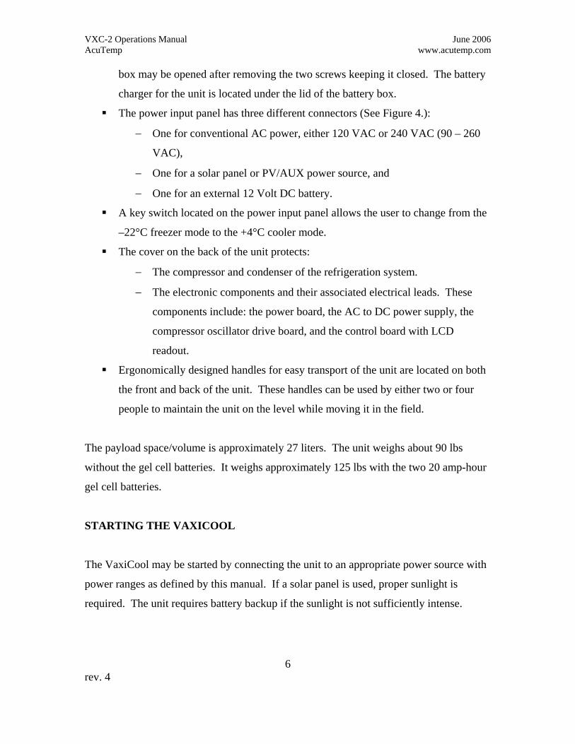
A schematic image of the display is shown in Figure 7. This shows the relative positions
of the information in the display. In the schematic example, the operating voltage is too
low, so the right alarm LED is yellow. This set of display conditions can occur when the
unit is first turned on and the batteries are not adequately charged to handle the initial
cool down task. Also in this schematic, the unit is set to –22°C (the freezer mode), which
is indicated by the last character on the first line. The upper left hand corner symbol will
appear in the +4°C (refrigerator) temperature mode.
VXC-2 Operations Manual June 2006 AcuTemp www.acutemp.com
15 rev. 4
Figure 7. Schematic of the LED indicators and LCD display.
VXC-2 Operations Manual June 2006 AcuTemp www.acutemp.com
16 rev. 4
MAINTENANCE
WARNING: Disconnect all external power before connecting or disconnecting
batteries. Also, disconnect all external power sources before performing
maintenance or before removing the black cover over the electronic section of the
unit. FAILURE TO COMPLY MAY RESULT IN INJURY OR DEATH.
The basic design of the VaxiCool relies on patented insulation technology, tight
temperature control using solid-state electronic computer control, and patented PCM
technology. The VaxiCool will perform with exceptional efficiency at –22°C and at
+4°C:
• At -22°C operation, the unit will operate for more than 8 hours with two properly
charged 14 amp-hour batteries (at 25°C ambient temperature).
• At 4°C operation, the unit will operate for more than 60 hours with two properly
charged 14 amp-hour batteries (at 25°C ambient temperature).
The VaxiCool is portable and self-powered when utilizing internal gel cell batteries. The
system is designed with lightning protection and will accept electrical power from
multiple sources, e.g. 12-volt batteries, solar panels, or a wide range of grid power (90 to
260 VAC with 47 to 63 Hz line frequencies, with no adjustment).
All operating power input to the system is distributed through the power board whose
location is shown in Figure 8. The same figure also shows the locations of the oscillator
board, power input panel, power supply and control board with LCD displays.

VXC-2 Operations Manual June 2006 AcuTemp www.acutemp.com
17 rev. 4
Figure 8. Location of Electronic Components
The internal batteries can only be charged if there is an external electrical input available
to the system (AC power or a solar panel). The battery charger is mounted on the
underside of the battery box lid behind a protective shield.
The VXC-2 operates on 12 VDC. Power from non-12 VDC sources (e.g. 120 VAC grid
power) is converted internally to 12 VDC. Operating on this 12 VDC internal source, the
oscillator board provides the correct power to the compressor. The compressor cools the
interior of the VaxiCool through an evaporator that surrounds the interior sides of the
unit. The temperature inside the unit is monitored via a thermistor, which is connected to
the control board. The control board also monitors the battery voltage, creates the signals

VXC-2 Operations Manual June 2006 AcuTemp www.acutemp.com
18 rev. 4
for the LCD readout, and adjusts system functions to maintain the appropriate internal
temperature.
To maintain good operation:
• The condenser must be kept cleaned of dust and dirt
• The external electrical connectors should be kept clean
• Lid gaskets should be kept clean and free of cuts and rips
• Batteries should be kept charged and terminals kept clean of corrosion
The system is protected from excessive currents by a series of fuses. The first set of fuses
is located within the input receptacle for AC current shown in the upper right corner of
Figure 4. Depending on the model of the input receptacle, one or two fuses are
required. The fuse rating is 3 amps, 250 V (5x20 mm size). The remaining six fuses (10
amp, 250 V 5x20 mm size) are located on the power board as shown in Figure 9. These
fuses are accessible by removing the compressor and electronics cover at the rear of the
unit.
Figure 9. Location of Fuses
VXC-2 Operations Manual June 2006 AcuTemp www.acutemp.com
19 rev. 4
WARRANTY
The VaxiCool is warranted to be free from defects in manufacturing and workmanship
for a period of one (1) year from the date of purchase F.O.B. Dayton, Ohio. This limited,
warranty covers repair or replacement, at the Company’s option, of components only. It
does not cover any costs related to or damage resulting from the use of the VaxiCool. The
owner of the VaxiCool must pay for insurance and shipping (and for overseas customers,
import/export duties) to and from Dayton, Ohio or the factory-designated service center.
The unit must be packaged such that it will not be damaged in transit; the Company will
not be responsible for any such damage. Therefore, the unit must be insured for its full
value.
AcuTemp reserves the right to change product specifications, materials used in
construction, component parts, suppliers and product design elements at any time in order
to provide the best product possible.
AcuTemp makes no representation or warranty, express or implied, with respect to the
suitability of the VaxiCool and its phase change materials for holding or carrying any
particular items or for any other purpose, including, without limitation, any implied
warranty of merchantability or fitness for a particular purpose.

VXC-2 Operations Manual June 2006 AcuTemp www.acutemp.com
20 rev. 4
Appendix A
Solar Panel Application
If you have purchased or wish to purchase the optional solar panel for keeping the
VaxiCool batteries charged via sunlight, selection of the solar panel is based on your
location, solar conditions, and duration of daylight and nighttime hours. Using panels
that are too small for your conditions will not adequately maintain a battery charge. If
you change the geographical location of your VaxiCool system, please check with factory
technical support to verify that your panel size does not need to change. Please contact
[email protected] for assistance.
The solar panel needs to be mounted in an appropriate manner per the instructions
provided with the panel, to ensure maximum use of sunlight. The cable that comes with
the solar panel will be the correct gauge and length, per factory specifications, and you
should not attempt to extend it without consulting the factory or panel manufacturer for
technical support.
The connector on the end of the solar panel cable will only fit into the PV/AUX
connector on the power input panel of the VaxiCool (Figure 4, page 9). It cannot be
mated accidentally to any other connector on the VaxiCool.
A properly selected solar panel will keep the internal batteries charged and the unit
running continuously under conditions typical for your location. The panel will supply
sufficient power to run the compressor during daylight hours and to charge the batteries
to ensure operation through the night or longer. It is important that a unit running on
solar panels not be disconnected from the panels during any daylight hours. Solar panels
receive most of their energy from ultraviolet light, which can partially penetrate cloud
cover. Do not assume that a cloudy day means you do not need to keep the panel
connected. On days when cloud cover is heavy, the battery may not charge completely,

VXC-2 Operations Manual June 2006 AcuTemp www.acutemp.com
21 rev. 4
however, it should gain some charge. Fully charged, the battery stores enough energy to
continue operating through a number of heavily clouded days.