operation and maintenance manual of positive displacement...
TRANSCRIPT

Operation and Maintenance Manual of Positive Displacement Pump
QT S S e r i e sT w i n S c r e w P u m p
www.qpumps.com
QTS-M04
suppor [email protected]

2
Operation and Maintenance Manual QTS Series Twin Screw Positive Displacement Pump
QTS-M04
About this Manual . . . . . . . . . . . . . . . . . . . . . . . . . . . . . . . . . . . . . . . . . . . . . . . . . . .
Safety . . . . . . . . . . . . . . . . . . . . . . . . . . . . . . . . . . . . . . . . . . . . . . . . . . . . . . . . . . .
Pump Operation . . . . . . . . . . . . . . . . . . . . . . . . . . . . . . . . . . . . . . . . . . . . . . . . . . . .
Know Your Pump . . . . . . . . . . . . . . . . . . . . . . . . . . . . . . . . . . . . . . . . . . . . . . . . . .
Maintenance: Pump assembly and disassembly . . . . . . . . . . . . . . . . . . . . . . . . .
CO
NT
ENT
3
5
8
1312
14
Q-Pumps S.A. de C.V. Warranty . . . . . . . . . . . . . . . . . . . . . . . . . . . . . . . . 3 General Information . . . . . . . . . . . . . . . . . . . . . . . . . . . . . . . . . . . . . . . . . . . 4 Damage or Loss During Shipment . . . . . . . . . . . . . . . . . . . . . . . . . . . . . . . 4 Receiving the Pump . . . . . . . . . . . . . . . . . . . . . . . . . . . . . . . . . . . . . . . . . . 4
Electrical Connections . . . . . . . . . . . . . . . . . . . . . . . . . . . . . . . . . . . . . . . . . 6Temperature . . . . . . . . . . . . . . . . . . . . . . . . . . . . . . . . . . . . . . . . . . . . . . . . . 6Moving Parts . . . . . . . . . . . . . . . . . . . . . . . . . . . . . . . . . . . . . . . . . . . . . . . . 6Lifting the Pump . . . . . . . . . . . . . . . . . . . . . . . . . . . . . . . . . . . . . . . . . . . . . . 6
Starting Up Procedure . . . . . . . . . . . . . . . . . . . . . . . . . . . . . . . . . . . . . . . . . 13Shutting Down Procedure . . . . . . . . . . . . . . . . . . . . . . . . . . . . . . . . . . . . . . 13Restarting Procedure . . . . . . . . . . . . . . . . . . . . . . . . . . . . . . . . . . . . . . . . . 13
Data Sheet . . . . . . . . . . . . . . . . . . . . . . . . . . . . . . . . . . . . . . . . . . . . . . . . . . 8Pump General Assembly . . . . . . . . . . . . . . . . . . . . . . . . . . . . . . . . . . . . . . . 10Pump Arrangements Assemblies . . . . . . . . . . . . . . . . . . . . . . . . . . . . . . . . 10QTS Rotors and Clearances . . . . . . . . . . . . . . . . . . . . . . . . . . . . . . . . . . . . 11Using Variable Frequency Drives . . . . . . . . . . . . . . . . . . . . . . . . . . . . . . . . . 11
Tools and Spare Parts . . . . . . . . . . . . . . . . . . . . . . . . . . . . . . . . . . . . . . . . . 14Oil and Oil Change . . . . .. . . . . . . . . . . . . . . . . . . . . . . . . . . . . . . . . . . . . . . 14Bill of Materials . . . . . . . . . . . . . . . . . . . . . . . . . . . . . . . . . . . . . . . . . . . . . . 15Torque Values . . . . . . . . . . . . . . . . . . . . . . . . . . . . . . . . . . . . . . . . . . . . . . . 15Exploded View . . . . . . . . . . . . . . . . . . . . . . . . . . . . . . . . . . . . . . . . . . . . . . 16Pump Disassembly . . . . . . . . . . . . . . . . . . . . . . . . . . . . . . . . . . . . . . . . . . . 17Removing the Rotors . . . . . . . . . . . . . . . . . . . . . . . . . . . . . . . . . . . . . . . . . . 17Mechanical Seals Replacement . . . . . . . . . . . . . . . . . . . . . . . . . . . . . . . . . 19 Uninstalling the Single Mechanical Seals . . . . . . . . . . . . . . . . . . . . . . . 20 Installing the Single Mechanical Seals . . . . . . . . . . . . . . . . . . . . . . . . . . 21 Uninstalling the Double Mechanical Seals . . . . . . . . . . . . . . . . . . . . . . . 23 Installing the Double Mechanical Seals . . . . . . . . . . . . . . . . . . . . . . . . . 25Rotor Assembly . . . . . . . . . . . . . . . . . . . . . . . . . . . . . . . . . . . . . . . . . . . . . . 29Rotor Synchronization . . . . . . . . . . . . . . . . . . . . . . . . . . . . . . . . . . . . . . . . . 31Important Notes . . . . . . . . . . . . . . . . . . . . . . . . . . . . . . . . . . . . . . . . . . . . . 35
Annex A: CIP . . . . . . . . . . . . . . . . . . . . . . . . . . . . . . . . . . . . . . . . . . . . . . . . . . . . . . . 39Annex B: Nut-and-Locknut Technique . . . . . . . . . . . . . . . . . . . . . . . . . . . . . . . . . 42
Base Allignment . . . . . . . . . . . . . . . . . . . . . . . . . . . . . . . . . . . . . . . . . . . . . . . . . . . .
Risks to consider . . . . . . . . . . . . . . . . . . . . . . . . . . . . . . . . . . . . . . . . . . . . . . . . . . . 37Troubleshooting . . . . . . . . . . . . . . . . . . . . . . . . . . . . . . . . . . . . . . . . . . . . . . . . . . . . 38

3
Operation and Maintenance Manual QTS Series Twin Screw Positive Displacement Pump
QTS-M04
ABOUT THIS MANUALTo ensure the best performance of your pump, please read this manual before starting it. You will find useful information and instructions for the assembly and disassembly procedures required for the necessary pump maintenance.
For any questions related to the operation, maintenance or installation, please contact your local distributor or directly to Q-Pumps:
Q-Pumps S.A. de C.V.Acceso “A” #103, Fracc. Industrial Jurica
Querétaro, Qro., México, 76130Call: +52 (442) 218 4570 y +52 (442) 103 3100
Fax: +52 (442) 218 4577E-mail: [email protected]
Web: www.qpumps.com
The information in this manual might change without notice, we recommend to visit our website for any updates.
Q-Pumps S.A. de C.V. WarrantyQ-Pumps guarantees that all manufactured and sold products are free from defects in materials and manufacture for a period of one (1) year from the date of shipment. The warranty does not apply to products which require repair or replacement due to what is considered normal wear. Conditions caused by normal wear include (but are not limited to standard rotors wear) casing, mechanical seals, gears and bearings wear.
Accidents, operating errors or improper maintenance are not covered by the warranty. Q-Pumps assumes no liability for incidental, accidental or consequential damages. The purchaser by acceptance of delivery assumes all liability for the consequences of use or misuse by it, its employees or third parties. Unless they are approved in advance, Q-Pumps does not assume any costs related to parts and / or service.
Q-Pumps disclaims any responsibility for modifications or conversions to the pump and the system. For security reasons and functionality use original parts only. The use of other parts voids the warranty and excludes liability for any consequences.
The pump is designed only for pumping fluids under established characteristics in the selection sheet. Any other use besides the intended one without the prior written consent of the manufacturer’s application, will result in disclaim of any responsibility from Q-Pumps.
If the pump is stored temporarily or indefinitely, avoid weather exposure and protect the connection ports with plastic plugs supplied with your pump. Turn the pump shaft by hand every two months to change the rotating position of the bearings. AB
OU
T T
HIS
MA
NU
AL
4
Operation and Maintenance Manual QTS Series Twin Screw Positive Displacement Pump
QTS-M04
General InformationEvery QTS pump is completely assembled, lubricated, synchronized, factory tested and ready for use. Standard maintenance practices are described in this manual. For more information, please see the Maintenance section. Following these guidelines will grant a long pump service life under a proper use and installed in a properly designed system.
If necessary to return the equipment under warranty, or for some other reason, contact Q-Pumps to receive a Return Material Authorization (RMA).
Damage or loss during shipmentIf you receive the equipment in poor condition or it is lost during transport, file a claim with the carrier immediately. The transport service provider is responsible for collecting the goods, Q-Pumps ensure they received it in perfect conditions.
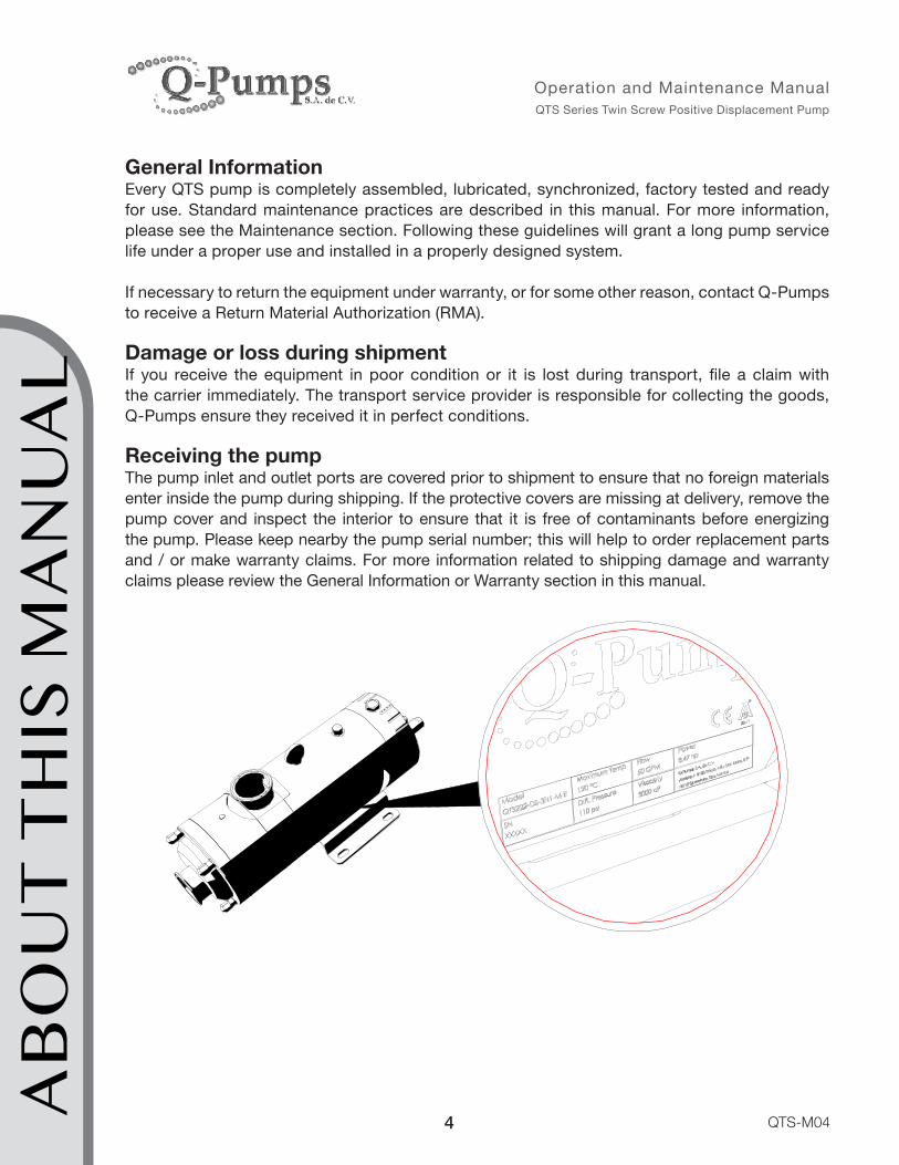
Receiving the pumpThe pump inlet and outlet ports are covered prior to shipment to ensure that no foreign materials enter inside the pump during shipping. If the protective covers are missing at delivery, remove the pump cover and inspect the interior to ensure that it is free of contaminants before energizing the pump. Please keep nearby the pump serial number; this will help to order replacement parts and / or make warranty claims. For more information related to shipping damage and warranty claims please review the General Information or Warranty section in this manual.
AB
OU
T T
HIS
MA
NU
AL
5
Operation and Maintenance Manual QTS Series Twin Screw Positive Displacement Pump
QTS-M04
SAFETYIMPORTANT: Read and understand this manual before installation, operation or maintenance of the pump. Installation, operation and maintenance in combination with inappropriate unsafe practices can cause serious individual risks or death, damage to the environment and the pump itself. Equipment damage caused by user negligence will void the pump warranty.
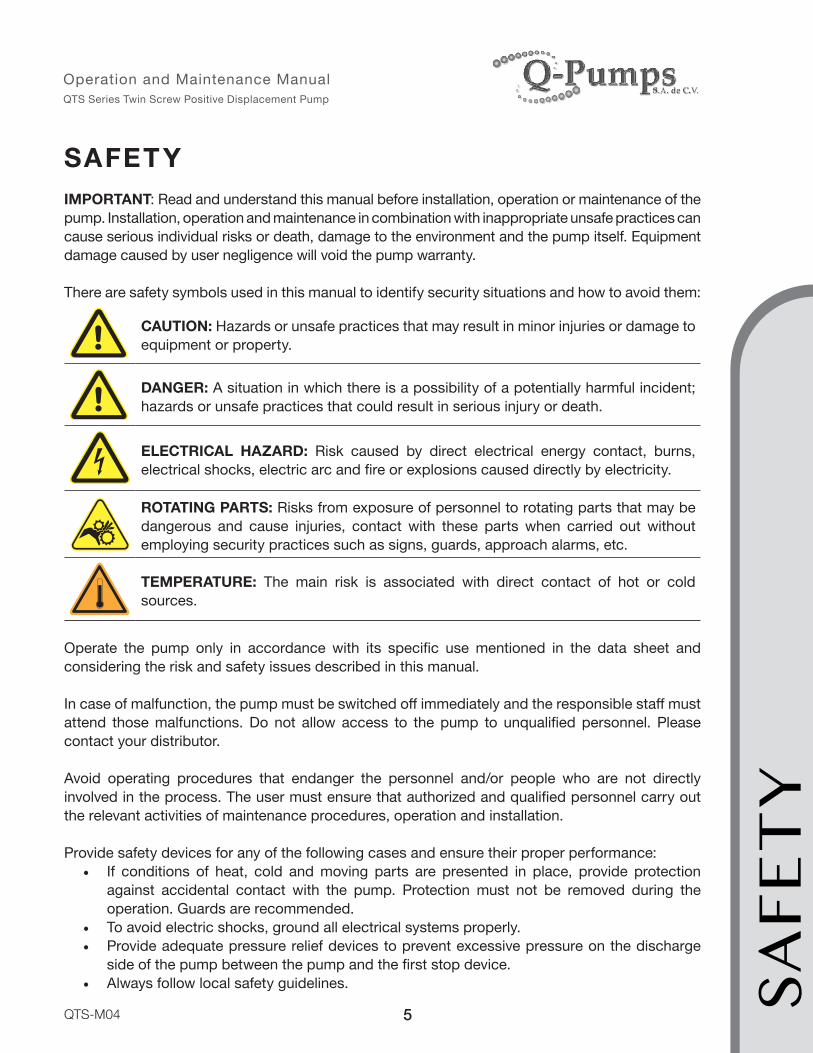
There are safety symbols used in this manual to identify security situations and how to avoid them:
CAUTION: Hazards or unsafe practices that may result in minor injuries or damage to equipment or property.
DANGER: A situation in which there is a possibility of a potentially harmful incident; hazards or unsafe practices that could result in serious injury or death.
ELECTRICAL HAZARD: Risk caused by direct electrical energy contact, burns, electrical shocks, electric arc and fire or explosions caused directly by electricity.
ROTATING PARTS: Risks from exposure of personnel to rotating parts that may be dangerous and cause injuries, contact with these parts when carried out without employing security practices such as signs, guards, approach alarms, etc.
TEMPERATURE: The main risk is associated with direct contact of hot or cold sources.
Operate the pump only in accordance with its specific use mentioned in the data sheet and considering the risk and safety issues described in this manual.
In case of malfunction, the pump must be switched off immediately and the responsible staff must attend those malfunctions. Do not allow access to the pump to unqualified personnel. Please contact your distributor.
Avoid operating procedures that endanger the personnel and/or people who are not directly involved in the process. The user must ensure that authorized and qualified personnel carry out the relevant activities of maintenance procedures, operation and installation.
Provide safety devices for any of the following cases and ensure their proper performance:• If conditions of heat, cold and moving parts are presented in place, provide protection
against accidental contact with the pump. Protection must not be removed during the operation. Guards are recommended.
• To avoid electric shocks, ground all electrical systems properly.• Provide adequate pressure relief devices to prevent excessive pressure on the discharge
side of the pump between the pump and the first stop device.• Always follow local safety guidelines. SA
FET
Y

6
Operation and Maintenance Manual QTS Series Twin Screw Positive Displacement Pump
QTS-M04
Electrical Connections
• A qualified and trained electrician should make the electrical connection to the motor.• Use safety equipment necessary to manipulate electricity.• Use appropriate signs in areas where electrical equipment is exposed.• The pump must be de-energized and secured to prevent startup before starting any work of
electrical equipment.• Use the right wire number according to the motor voltage and amperage.• Follow diagram connections shown on the motor nameplate; check the motor installation
manual for any questions.• Isolate and protect the terminal ports and connections.• Make sure the rotation of the pump is correct.• The motor of your pump has been tested and was selected to meet the requirements of a
specific application. The motor amperage consumption should be within the range indicated on the motor nameplate for a proper operation.
• The user is responsible for the safety and proper operation of equipment when special and others motors are used (not supplied by Q-Pumps).
Temperature
The QTS Series are designed to work in a normal temperature range between -40 °C (-40 °F) and 100 °C (212 ° F). Be careful when touching the body and gear case to avoid burns when the temperature rises. If the application requires a higher temperature range please contact Q-Pumps to be advised about this case.
Moving Parts
The principal operation of the QTS Series is by the turning of a pair of synchronized rotors which can trap any foreign object and get stuck due to an invalid equipment operation. Never operate the pump without the front cover properly in place.
The gearbox contains rotating parts; never operate the pump without the cover of the gear case. Watch precautions with free turning shafts of drive elements when not properly coupled to the pump. Likewise, do not operate the pump without the coupling guard placed in position.
Lifting the Pump
Carefully transport the equipment avoiding contact, drops or damage. To prevent this situation the QTS Series are provided with an eye bolt located on the gear case for lifting.
The same way, gear motors and motors have an eye bolt (or at least one hole for using this part) located in the body.SAFE
TY

7
Operation and Maintenance Manual QTS Series Twin Screw Positive Displacement Pump
QTS-M04
Use proper equipment such as elevators or cranes together with slings or straps with the right capacity to lift the total weight.
Take precautions and follow the manufacturer recommendations to use the slings or straps.
In the case of lifting assemblies motor/gear-motor coupled to the pump, always try to lift them up simultaneously. Be sure to place the pump assembly on a stable surface. Once assembly is positioned in place, check that the screws are properly tightened and that the assembly is aligned; follow directions for coupling alignment section in this manual for this purpose.
Corre
ctIn
corre
ct
SAFE
TY
8
Operation and Maintenance Manual QTS Series Twin Screw Positive Displacement Pump
QTS-M04
KNOW YOUR PUMPCongratulations! You’ve acquired a high technology and quality equipment for your sanitary pumping solutions. QTS Series is the best solution toward other brands in the market due to its special characteristics:
• Ideal to pump low and high viscosity fluids (up to 1,000,000 cP).• All wet parts in contact with the fluid are made of 316L stainless steel.• Ideal for handling abrasive products.• Can speed up to 3,000 rpm depending on the pump model, type of fluid and application.
It is a bidirectional pump, so it can help recovering line product.• Can be used as process pumps as well as a CIP pump reducing cost in additional
equipment and timing.• Suction and discharge enlarged option available.• Totally drainable.• Even when running at high speed, there is no rotor/rotor/body contact.• Meets 3A and EHEDG (European Hygienic Engineering and Design) standards. • Low NPSH requirement thanks to its high suction capacity.• Can pump fluids with up to 60% entrained air.
Data SheetThis document is linked to the serial number of your pump which is printed on the gear case. You can find valuable information such as the pump model, type and material of the mechanical seals as well as operating data (application) and the CIP process data requirements. These data must meet the equipment selection. Take into consideration that operating your pump under different circumstances can void the warranty. Please keep the data sheet for any clarification.
KN
OW
YO
UR
PU
MP

9
Operation and Maintenance Manual QTS Series Twin Screw Positive Displacement Pump
QTS-M04
Data Sheet
Data Sheet
Customer: Example
Model QTS 203 Operating Conditions VFD
Certification 3A / EHEDG Capacity 60 gpm
Screw material AISI 316L Diff. pressure 50 psi
Housing material AISI 316L Pump speed 600 rpm 60 Hz
Shaft material 17-4 PH Temperature 30 °C
Screw hardening Yes Viscosity 500 cPs
Housing hardening Yes Particle size < 0.5 in
Rotation (Front) CW bhp 4.9 hp
Sealing Single mechanical seal Nominal power 7.5 hp
Sealing material SiC/C
Elastomer material EPDM CIP
Suction port location Front cover port Max. pump speed 1800 rpm 90 Hz
Suction port size Tri-Clamp 2" Max. CIP time 30 min
Discharge port size Tri-Clamp 2" Max. diff. pressure 50 psi
Thermal jacket No Piping size 2 in
Drive Electric motor with gear reduction
VFD Yes
KN
OW
YO
UR
PU
MP

10
Operation and Maintenance Manual QTS Series Twin Screw Positive Displacement Pump
QTS-M04
Pump General AssemblyThe pump uses twin screw rotors, when rotating they move the fluid through the casing. The elements inside the gear case are responsible for transmitting the synchronized movement and the force required for pumping the fluid; gears, bearings, spacers, and shafts are inside the gear case.
1. Front cover (with port connection, typically inlet)
9
106
7
5
4
1
4. Pump casing5. Back cover (with port connection,
usually outlet)6. Gear case7. Pump base plate (NEMA/IEC)9. Drive shaft
10. Gear case cover
Pump Arrangements AssembliesThe QTS series pumps can be delivered coupled to a drive element in different ways to solve one specific application. They can be ordered and delivered as follows:
Pump Only. In this case the pump is supplied with a drive shaft for coupling, does not include motor/gear-motor, coupling or base.
Pump Coupled to a Motor Assembled on a Base. This assembly includes a motor with a coupling, coupling guard and base.
KN
OW
YO
UR
PU
MP
11
Operation and Maintenance Manual QTS Series Twin Screw Positive Displacement Pump
QTS-M04
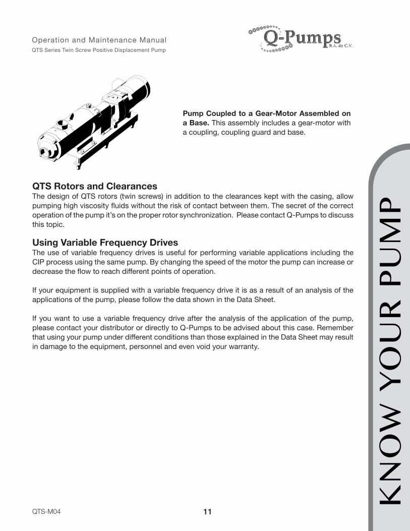
Pump Coupled to a Gear-Motor Assembled on a Base. This assembly includes a gear-motor with a coupling, coupling guard and base.
QTS Rotors and ClearancesThe design of QTS rotors (twin screws) in addition to the clearances kept with the casing, allow pumping high viscosity fluids without the risk of contact between them. The secret of the correct operation of the pump it’s on the proper rotor synchronization. Please contact Q-Pumps to discuss this topic.
Using Variable Frequency DrivesThe use of variable frequency drives is useful for performing variable applications including the CIP process using the same pump. By changing the speed of the motor the pump can increase or decrease the flow to reach different points of operation.
If your equipment is supplied with a variable frequency drive it is as a result of an analysis of the applications of the pump, please follow the data shown in the Data Sheet.
If you want to use a variable frequency drive after the analysis of the application of the pump, please contact your distributor or directly to Q-Pumps to be advised about this case. Remember that using your pump under different conditions than those explained in the Data Sheet may result in damage to the equipment, personnel and even void your warranty.
KN
OW
YO
UR
PU
MP

12
Operation and Maintenance Manual QTS Series Twin Screw Positive Displacement Pump
QTS-M04
BA
SE A
LIG
NM
ENT
BASE ALIGNMENTPump / base assemblies are aligned in Q-Pumps factory prior to shipment. However assembles must be checked prior operation to avoid any misalignment. Misalignment may cause unneces-sary wear and shorten the life of the pump. You can notice misalignment with excess noise and vibrations. To check and align the pump to its drive first remove the coupling guard.
COUPLING GUARD
Proceed to verify the angular alignment by measuring the space between the couplings in both vertical and horizontal direction. The measured space has to be equal at both sides of the coupling use shims in the pump base or motor base if needed. Proceed to align the pump and drive para-llel to the axis of rotation. Use a straight edge in both top and side of the couplings to guarantee parallelism.
ANG
ULAR
ALIG
NMEN
TPA
RALE
LL A
LIGNM
ENT
TOP VIEW SIDE VIEW

13
Operation and Maintenance Manual QTS Series Twin Screw Positive Displacement Pump
QTS-M04
PUMP OPERATIONFollow these steps for the proper operation of your pump before, during and after starting it up. Remember that the correct operation of the pump ensures proper performance and long service life. Failure to follow these recommendations could result in damage to the pump voiding the warranty.
Starting Up ProcedureBefore starting the equipment, ensure the following:
• Oil is on its level; otherwise fill the gear case until the oil fills the sight glass.• Mechanical seals are not leaking. Double mechanical seals must be lubricated without
exception. The pump is able to run dry for a short period of time (not recommended). Prevent dry starts to avoid damaging the mechanical seals.
• Jackets are properly connected and have adequate supply of heating or cooling medium.
• The pump is cleaned and sterilized. • The pump is primed with the fluid to be pumped.• In order to prevent cavitation, check the valves in the suction side are fully open.• The valves on the discharge side are fully open to prevent overpressure inside the
pump.• Security measures are taken at the discharge side of the pump to protect against
overpressure (open valves, corresponding jacketed piping, by-pass, and recirculation or pressure relief valves).
• The manometers at the discharge are operational.
When starting the motor, check and adjust the operating speed according to the data sheet, after the motor reaches the operation speed search for leaks.
Shutting Down ProcedureAfter shutting down the motor check the following:
• The pump slows softly. If a variable frequency drive is used both acceleration and deceleration ramps can be programed.
• If the pump has double mechanical seal even when the pump is stopped keep the supply of the buffer fluid until it is depressurized.
• If a jacket is used please adjust it until the pump temperature goes below a 100 °C/212 °F.
Restarting ProcedureBefore restarting the pump check the smooth rotation of the shafts without restrictions and repeat the starting up procedure.
PUM
P O
PER
ATIO
N

14
Operation and Maintenance Manual QTS Series Twin Screw Positive Displacement Pump
QTS-M04
MAINTENANCE: Pump Assembly and DisassemblyTo assemble and disassemble the pump, follow the recommendations described ahead. Always use original spare parts and follow the instructions in this manual. Not following these recommendations could result in damage to the equipment and void the warranty. Remember to read the safety recommendations.
Tools and Spare PartsSome spare parts such as mechanical seals, O-rings and gaskets kits may be required for solving any contingency.
The following tools are provided within the pump:1. Special wrench to tighten lock nut (gear case).2. Hook for O–rings removal.
You may require these tools:1. Set of ball end hexagonal L-keys in standard sizes: 3/16”, 1/4”, 5/16” and 3/8”.2. Steel thicknesses gages in sizes of 0.001”, 0.002” and 0.005”.3. Socket wrench and set of six points hexagonal sockets.4. Wrenches 7/8”, 1” and 1 ½”.5. It is very important to have a torque wrench (capacity from 4 to 50 lb·ft).
Also you may need FDA grade silicone base grease for incidental contact.
Oil and Oil ChangeThe pump comes with Food Grade Mineral Oil from fabric. All pump sizes use ISO VG-68 oil.
Oil change is needed if one of the following conditions is present:
First oil change 240 hoursNon-continuous operation* 2000 hoursContinuous operation** 2500 hours or 4 months (whichever comes first)
* Twelve or more pump startups per day** Less than twelve pump startups per day
MA
INT
ENA
NC
E

15
Operation and Maintenance Manual QTS Series Twin Screw Positive Displacement Pump
QTS-M04
MA
INT
ENA
NC
E
lb·ftlb-ftlb-ftlb-ftlb-ftlb-in
Bill of Materials Please use this table and diagram to identify every component to be assembled.
Bill of Materials:1 Front cover 19 Synchronization ring 37 Front bearing
2 Left rotor 20 Tapered driven ring 38 Rear bearing
3 Right rotor 21 Cover nut 39 Lock washer
4 Pump casing 22 Flat washer 40 Socket head cap screw
5 Back cover 23 Spring washer 41 Drive gear
6 Gear case 24 Set screw 42 Driven gear
7 Pump base plate 25 Dowel pin 43 Bearing lock washer
8 Driven shaft 26 O-ring 44 Bearing lock nut
9 Drive shaft 27 Gasket 45 Lock washer
10 Gear case cover 28 Socket head cap screw 46 Socket head cap screw
11 Rotor nut 29 Front seal 47 O-ring
12 Mechanical seal 30 Flat washer 48 Pressure release valve
13 Button head set screw 31 Hexagon bolt 49 Rear seal
14 Stud 32 Eye bolt 50 Oil sight glass
15 Bearing spacer 33 Hexagonal bolt 51 Hex Plug
16 Gear spacer 34 Gear key 52 Plug
17 Retaining flange 35 Coupling key 53 Plug
18 Tapered drive ring 36 Lock ring 54 Nipple flushNote: Depending on the model, some components may not be included.
Torque ValuesUse the following torque table to tighten each item when indicated on the manual:
# Part Piece QTS 100 QTS 200 QTS 30021 Front cover nuts 15 20 3011 Rotor nut 35 40 5040 Socket head cap screw (bearings) 10 15 2044 Bearing lock nut 25 30 4046 Socket head cap screw (sync ring) 2.1 4.2 6.25
25 50 75Coupling set screws 10 lb·ft for all models. Hexagonal bolts/hexagonal nuts motor/base, pump/base, 40 lb·ft. Any other screw 10 lb·ft.
Minimum Thickness GageModel Value
100 0.007 in200 0.007 in300 0.010 in
Note: Value at both flanks of rotor

16
Operation and Maintenance Manual QTS Series Twin Screw Positive Displacement Pump
QTS-M04
1
4
2
12A-J
2X
3
6
8
9
152X
172X
10
41
42
18
466X
7
112X
5
144X
432X
214X
224X
262X
232X
242X
254X
272X
282X
292X
314X30
4X
32
524X
334X
35
364X
372X
386X
3912X
4012X
19
456X 20
47
49
502X
512X
442X
16
34
138X
12K-T
2X
48
Expl
oded
Vie
w
MA
INT
ENA
NC
E

17
Operation and Maintenance Manual QTS Series Twin Screw Positive Displacement Pump
QTS-M04
MA
INT
ENA
NC
E
Be sure to read and understand the Safety section of this manual before servicing your pump.
De-energize the unit and lock out the mechanism.
Handle all wet parts with caution; prevent harsh contact or scratches and always place them on a clean surface to avoid damage.
The preventive maintenance procedures and inspection comprises the change of the mechanical seals, O-rings and gaskets replacement, checking the oil level, checking the alignment of the coupling as well as noise and vibration issues.
Removing the Rotors1. Remove first the cover nuts (21) and flat washers (22), use a wrench or a six points female socket. Remove the front cover (1).
2. Take off carefully the front cover gasket (27), you may use the O-rings hook.
3. Remove the pump housing (4) carefully. It is fixed and centered over the back cover (5) using dowel pins (25). Just pull out to slide the housing through the housing studs (14). The pins may be pulled out along the housing or stay on the back cover. You can remove also the studs to increase the working area. The plug (53) is just for sealing a drill on the housing which has not a specific use.
Note: To remove the studs you may use the nut-and-locknut technique (see annex B).
27
1
22
21
5
14
25
4
53
4. Block the rotors with the aid of a wrench using the drive shaft (9) end. Using a six points female socket loosen the rotor nuts (11). First loosen the left side rotor (2) nut torque, then change to the

18
Operation and Maintenance Manual QTS Series Twin Screw Positive Displacement Pump
QTS-M04
right side rotor (3) and just loosen the torque of the second nut. Slowly loosen simultaneously the two rotor nuts until both are out. 5. The objective to loosen both nuts slowly will allow taking the rotors out uniformly along the shafts with no contact between each other.
311
9
2
6. Remove the O-rings (26), spring washers (23) and the rotor nut socket set screws (24). Sometimes the socket set screws may remain installed on the shafts, to remove them use a hexagonal key.
7. Take off the gasket (27) placed on the back cover. Sometimes this gasket may get stuck to the casing, pull out carefully to avoid damaging it whit the studs or rotors. Pull straight out both rotors along the shafts.
27
24 23
26
8. You have finished the removal of the rotors procedure. Every time you replace the rotors be sure to perform the synchronization procedure to guaranty the right assembly. Now continue with the replacement of the mechanical seals.
MA
INT
ENA
NC
E

19
Operation and Maintenance Manual QTS Series Twin Screw Positive Displacement Pump
QTS-M04
Mechanical Seals Replacement 1. Here is a description of the procedures for inspection and replacement of the mechanical seals. Every pump has two mechanical seals.
12J
12H12G
12F
12E
12D
12C12B
12A
12J
12H12G
12F
12E
12D
12C12B
12A
2. Single mechanical seal kit: it contains components 12A to 12J.
3. Double mechanical seal kit: It contains all components of the single mechanical seal plus components 12K to 12T; in this case the stainless steel seal housing (12J) is replaced by the seal housing (12L) which is already included on the double mechanical seal kit.
4. The mechanical seal should be installed using your hands only. No special tools are required unless it is indicated. You may use a hook to take out the O-rings from their grooves. Be careful not to scratch the seal faces.
12F
12N
12A
12R
12T12S
12Q
12P
12M
12L12K
12H12G
12E
12D12C
12B
12F
12N
12A
12R
12T12S
12Q
12P
12M
12L12K
12H12G
12E
12D12C
12B
5. Look for defects on the sealing surfaces such as scratches or wear. If a replacement is necessary, it is recommended to change all components to ensure proper operation. If an O-rings is deformed or damaged it is recommended also to replace the entire set of O-rings. M
AIN
TEN
AN
CE
20
Operation and Maintenance Manual QTS Series Twin Screw Positive Displacement Pump
QTS-M04
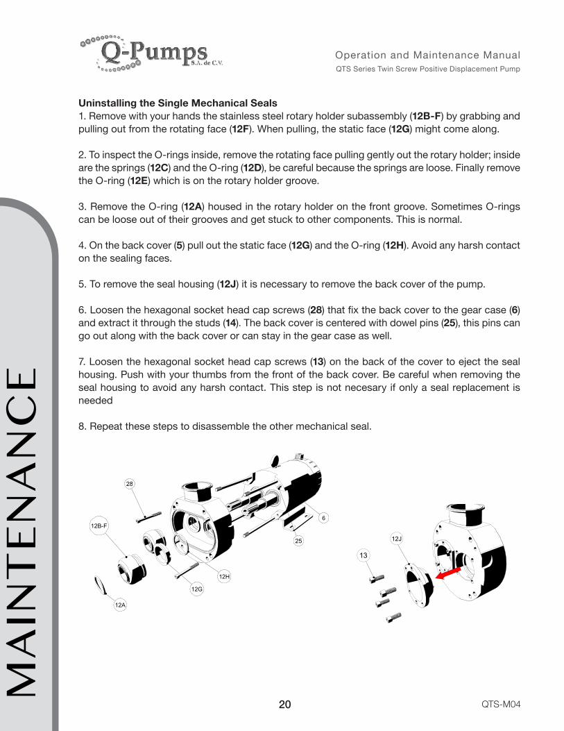
Uninstalling the Single Mechanical Seals1. Remove with your hands the stainless steel rotary holder subassembly (12B-F) by grabbing and pulling out from the rotating face (12F). When pulling, the static face (12G) might come along.
2. To inspect the O-rings inside, remove the rotating face pulling gently out the rotary holder; inside are the springs (12C) and the O-ring (12D), be careful because the springs are loose. Finally remove the O-ring (12E) which is on the rotary holder groove.
3. Remove the O-ring (12A) housed in the rotary holder on the front groove. Sometimes O-rings can be loose out of their grooves and get stuck to other components. This is normal.
4. On the back cover (5) pull out the static face (12G) and the O-ring (12H). Avoid any harsh contact on the sealing faces.
5. To remove the seal housing (12J) it is necessary to remove the back cover of the pump.
6. Loosen the hexagonal socket head cap screws (28) that fix the back cover to the gear case (6) and extract it through the studs (14). The back cover is centered with dowel pins (25), this pins can go out along with the back cover or can stay in the gear case as well.
7. Loosen the hexagonal socket head cap screws (13) on the back of the cover to eject the seal housing. Push with your thumbs from the front of the back cover. Be careful when removing the seal housing to avoid any harsh contact. This step is not necesary if only a seal replacement is needed
8. Repeat these steps to disassemble the other mechanical seal.
28
12A
6
25
12H
12G
12B-F
28
12A
6
25
12H
12G
12B-F
12J
13
MA
INT
ENA
NC
E

21
Operation and Maintenance Manual QTS Series Twin Screw Positive Displacement Pump
QTS-M04
MA
INT
ENA
NC
E
Installing the Single Mechanical Seals1. You do not require special tools to install the mechanical seals, use your hands to assemble the components.
2. Place the dowel pins (25) on the gear case, slide them smoothly, if you find difficulties stop and check the surface finish of the pins and the drills on the gear case; replace the pins if necessary and clean the inside drills (may use scrub a sponge).
3. Place the seal housing (12J) into the back cover. It has a drag pin in the front for the static face (12G)
4. Tighten the button head screws (13) to secure the seal housing in the back cover.
13
12J
13
12J
5. Place the O-ring (12H) on the static face (12G)
6. Proceed to place the static face (12G) in the back cover. Make sure the notch is aligned with the drag pin. There is no physical contact between the static face and the seal housing, the O-ring limits the position of the static face. This step is crucial for the right assembly of the mechanical seal; failing to do so properly can cause damage to the mechanical seals, the rotors and can even alter the integrity of the pump.
13
12J
12H12G
13
12J
12H
NOTCH
DRAG PIN
12G

22
Operation and Maintenance Manual QTS Series Twin Screw Positive Displacement Pump
QTS-M04
12LDRAG PIN
12H
NOTCH
12G
7. Repeat this procedure with the next housing.
8. Take the back cover (with the seal housing inside) and carefully slide along the studs and shafts pushing it to the back until making contact with the gear case; use the dowel pins to center it with the gear case.
WARNING! All four dowel pins must always be placed before running the pump. Not doing so will cause severe damage to the pump.
9. Fix the back cover to the gear case with the hexagonal socket head cap screws (28) and tighten them firmly.
252528
10. Place the O-ring (12D) on the inside groove of the stainless steel collar (12B). Insert the springs (12C) on the inside drills on the collar. 11. Lubricate the inside diameter of the O-ring (12E) and place it on the inside groove of the holder and make sure it is fixed.
12. Take the rotating face (12F) and insert it into the O-ring; the holder pins must fit the notches on the rotating face. Push with your hand against the holder until the springs are
compressed and the rotating component stays inside the holder.
13. It is important that the notches of the rotating face fit the holder pins; the physical contact is lead by the O-ring and the springs with no contact between metal and the rotating face. This step is crucial for the right assembly of the mechanical seal; failing to do so properly can cause damage to the mechanical seals, the rotors and can even alter the integrity of the pump. Place the O-ring (12A) into the holder front groove. This completes the subassembly of the rotating part of the seal.
MA
INT
ENA
NC
E
12E12F
12D
12B
12A
12C

23
Operation and Maintenance Manual QTS Series Twin Screw Positive Displacement Pump
QTS-M04
14. With the subassembly ready, insert the rotary holder on the shaft and push smoothly until it reaches the static face placed previously on the back cover. Repeat this procedure to install the other single mechanical seal on the next shaft.
15. At this point you have already assembled the single mechanical seals, continue with the assembly of the rotor
Uninstalling the Double Mechanical Seals1. Remove with the hand the stainless steel rotary holder subassembly (12B-F) by grabbing and pulling out from the rotating face (12F). When pulling, the static face (12G) might come together.
2. To inspect the O-rings inside, remove the rotating face pulling gently out the rotary holder; inside are the springs (12C) and the O-ring (12D), be careful because the springs are free. Finally remove the O-ring (12E) which is on the rotary holder groove.
3. Remove the O-ring (12A) housed in the rotary holder on the front groove. Sometimes O-rings can be loose out of their grooves and get stuck to other components.
4. On the back cover (5) side pull out the static face (12G) and the O-ring (12H). Avoid any harsh contact on the sealing faces.
5. To remove the seal housing (12L), O-rings (12K and 12N), springs (12M) and the static face of secondary seal (12P) it is necessary to remove the back cover of the pump. M
AIN
TEN
AN
CE
12P
28
12A
6
12Q-T
25
12H
12G
12B-F
12P
28
12A
6
12Q-T
25
12H
12G
12B-F

24
Operation and Maintenance Manual QTS Series Twin Screw Positive Displacement Pump
QTS-M04
6. Loosen the hexagonal socket head cap screws (28) that fix the back cover to the gear case (6) and extract it through the studs. The back cover is centered by dowel pins (25), this pins can come out with the back cover or stay in the gear case.
7. When extracting the back cover it is possible that the rotating face (12Q) comes attached to the secondary static face (12P); handle it with care to prevent any harsh contact to the seal faces with the shafts.
8. Loosen the hexagonal socket head cap screws (13) on the back of the cover to eject the seal housing. Push with your thumbs from the front of the back cover. Take caution when removing the housing to avoid any harsh contact.
9. Take away the O-ring (12K) on the housing using the O-ring hook.
10. To remove the static face of the secondary mechanical seal (12P) hold the housing with the static face looking up and pull with your thumbs.
12M
12L
12M
12N
12L
12P
Note: Always place the seal face looking up to prevent the springs from falling out.
11. Using the O-ring hook, remove the O-ring (12N). Remove the springs (12M) if necessary.
12. To extract the rotating components of the secondary mechanical seal pull out of the shaft the seal face (12Q) and remove the O-ring (12R) located inside this rotating seal face.
13. With a hexagonal key, loosen the set screws (12T) from the drive ring (12S) and pull it out if needed.14. Repeat these steps to uninstall the rest of the components of the other double mechanical seal.
12K-O
13
12K-O
13
MA
INT
ENA
NC
E

25
Operation and Maintenance Manual QTS Series Twin Screw Positive Displacement Pump
QTS-M04
MA
INT
ENA
NC
E
Installing the Double Mechanical Seals1. You do not require special tools to install the mechanical seals, use your hands to place the components into the assembly.
2. Place the dowel pins (25) on the gear case, slide them smoothly, if you find difficulties stop and check the surface finish of the pins and the drills on the gear case; replace the pins if necessary and clean the inside drills (may use scrub sponge).
3. Place the set screws (12T) in the drive ring (12S) using a hexagonal key. The screws must not pass through the inner diameter of the drive ring. Slide the ring on the shafts until the end and tight the set screws.
4. Insert the O-ring (12R) into the groove on the rotating face of the secondary mechanical seal (12Q) and slide them together on the shafts until reaching the drive ring. Make sure the set screws fit the notches on the rotating face.
5. Repeat these two last steps with the other rotating components of the double mechanical seal.
12T
DRAG PIN
NOTCH
12S
12R12Q
7. The seal housing (12L) has a drag pin in the front for the static face of the primary mechanical seal (12G) and two drag pins on the inside for the static face of the secondary mechanical seal (12P).
8. Place O-ring (12K) in the outside groove of the seal housing (12L).
9. Continue placing the springs (12M) inside the seal housing.

26
Operation and Maintenance Manual QTS Series Twin Screw Positive Displacement Pump
QTS-M04
12M
12L
12N12P
MA
INT
ENA
NC
E
12L
12H
NOTCH
DRAG PIN
12G13
12L
12H
NOTCH
DRAG PIN
12G
12K-O
13
12K-O
13
10. Place the O-ring (12N) on the static face of the secondary seal (12P) and insert it on the seal housing (12L); match the notches with the pins on it. Press evenly with both hands until the element gets completely inside the housing. If the pins are not aligned with the notches the element can be damaged; the final position is determinate by the spring and the O-ring so there should be no contact between metal and the static face of the secondary mechanical seal.
14. The static face of the primary mechanical seal (12G) has a notch to prevent rotation. Place O-ring (12H) on this element and insert both on the pump housing. Be sure the notch matches the drag pin on the seal housing (12L) and push gently until the element gets completely inside; the final position is determined by the O-ring so there should be no contact between metal and the static face of the primary mechanical seal.
11. Continue placing the seal housings (with seal faces and O-rings) inside the back cover (5).
12. Tighten the hexagonal socket head cap screws (13) to secure the seal housing in the back cover.
13. Repeat this procedure with the next seal housing.
12H
12G
12LDRAG PIN
NOTCH

27
Operation and Maintenance Manual QTS Series Twin Screw Positive Displacement Pump
QTS-M04
15. This step is crucial for the right assembly of the double mechanical seal, failure to do so properly can cause damage to the pump.
16. Take the back cover (with the seal housing inside) and carefully slide thru the studs and shafts pushing it to the back until making contact with the secondary rotating face (12Q) ; use the dowel pins to center the part with the gear case.
WARNING! All four dowel pins must always be placed before running the pump. Not doing so will cause severe damage to the pump.
17. Fix the back cover to the gear case with the hexagonal socket head cap screws (28) and tighten them firmly.
18. Place the O-ring (12D) on the inside groove of the stainless steel rotary holder (12B). Insert the coil springs (12C) on the inside drills of the holder.
19. Lubricate the inside diameter of the O-ring (12E) and place it on the inside groove of the holder and make sure it is fixed.
MA
INT
ENA
NC
E12E
12F
12D
12B
12A
12C
252528
28
Operation and Maintenance Manual QTS Series Twin Screw Positive Displacement Pump
QTS-M04
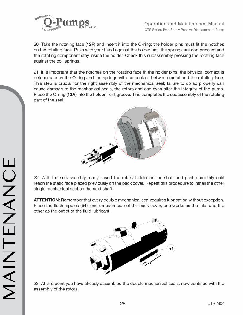
20. Take the rotating face (12F) and insert it into the O-ring; the holder pins must fit the notches on the rotating face. Push with your hand against the holder until the springs are compressed and the rotating component stay inside the holder. Check this subassembly pressing the rotating face against the coil springs.
21. It is important that the notches on the rotating face fit the holder pins; the physical contact is determinate by the O-ring and the springs with no contact between metal and the rotating face. This step is crucial for the right assembly of the mechanical seal; failure to do so properly can cause damage to the mechanical seals, the rotors and can even alter the integrity of the pump. Place the O-ring (12A) into the holder front groove. This completes the subassembly of the rotating part of the seal.
22. With the subassembly ready, insert the rotary holder on the shaft and push smoothly until reach the static face placed previously on the back cover. Repeat this procedure to install the other single mechanical seal on the next shaft.
ATTENTION: Remember that every double mechanical seal requires lubrication without exception. Place the flush nipples (54), one on each side of the back cover, one works as the inlet and the other as the outlet of the fluid lubricant.
5454
23. At this point you have already assembled the double mechanical seals, now continue with the assembly of the rotors.MA
INT
ENA
NC
E

29
Operation and Maintenance Manual QTS Series Twin Screw Positive Displacement Pump
QTS-M04
MA
INT
ENA
NC
E
Rotor Assembly1. Make sure the mechanical seals are properly installed before assembling the rotors. If the studs (14) were removed place them back. Insert firmly the gasket (27) on the back cover groove.
Note: To place the studs you may use the nut-and-locknut technique (see annex B).
2. Shafts and rotors are marked on the front face with dots to indicate the position of the rotor relative to the spline on the shaft; the rotors are also marked to identify which is the right rotor (3) and the left rotor (2), it is important to match each rotor with its respective shaft for the right operation of the pump.
3. Take both rotors together with your hands and mesh them so the front faces match are leveled. Turn the drive shaft (9) and the rotors so the dots correspond.
4. Slide the rotors together onto the shafts. Some alignment might be needed. By effect of the mechanical seals the rotors have not yet reached their final position; it is necessary to tighten the nuts.
5. Place the set screws (24), the spring washers (23) and the O-rings (26) on the
rotor nuts (11). Assembly the rotor nuts and tighten the rotor nuts as follows:
27
24 23
26
6. Block the drive shaft (9) with the aid of a wrench to prevent rotation of the rotors.
7. Tighten by hand the rotor nuts (11) simultaneously as far as you can; then use a six points female socket to tighten the nuts. Gradually tighten both nuts simultaneously to avoid contact between them.
8. When the rotors reach their end position with the mechanical seals and shafts, tighten the nuts with the torque values according to the pump model. The front faces of the rotors should be aligned.

30
Operation and Maintenance Manual QTS Series Twin Screw Positive Displacement Pump
QTS-M04
9. Using thickness gages, check the clearances between the rotors turning them slowly and introducing one gage at every point where the rotors are meshed. A practical way is to put the gage between the rotors in the front side and slowly rotate them so the gage moves along the rotors by its rotation. If the clearances do not comply (according to the pump model) is probable that the synchronization is not correct.
10. Once you have tightened and checked the rotor clearances continue closing the pump. Place the dowel pins (25) inside the holes on the back cover.
WARNING! Dowel pins must always be placed before running the pump. Not doing so will cause severe damage to the pump.
11. Insert the casing (4) carefully, it should be mounted and centered on the back cover (5) with the dowel pins. Push back to slide through the studs (14). The plug (53)
on the casing does not have a specific function.
12. Insert gasket (27) into the groove on the front cover (1) and close the pump; use the pocket in the front cover as a guide for assembling it with the casing.
13. Secure the front cover with the washers (22) and nuts (21); tighten using a wrench or a six points female socket. Remember to use the corresponding torque values according to the pump model. This concludes the rotor assembly.
5
14
25
4
5327
1
22
21MA
INT
ENA
NC
E

31
Operation and Maintenance Manual QTS Series Twin Screw Positive Displacement Pump
QTS-M04
1. Once the pump is disassembled, proceed to drain the oil in the gearbox. Use the cap nut (51) on the bottom of the gear case cover (10). If the oil is in good condition, keep it in a closed reservoir in order to avoid contamination. If the oil is dirty change it with new one. View oil section.
2. Remove the coupling key (35) from the drive shaft (9).6
10
35
51
6
10
35
Rotor Synchronization
9
1047
33
9
1047
33
3. Loosen the hexagonal bolts (33) and pull back the gear case cover. Inside are the gears that drive the pump. The drive gear (41) is driven with a key, while the driven gear (42) is locked by tapered rings.
Note: The tapered rings while loosen will make the idle gear rotate without transmitting any motion to the shaft. If the tapered rings are tighten, the idle gear will rotate with the shaft.
4. Undo the socket head cap screws (46) and remove them all. All screws have a lock washer (45).
42
46
41
42
46
4145
46
45
46
MA
INT
ENA
NC
E

32
Operation and Maintenance Manual QTS Series Twin Screw Positive Displacement Pump
QTS-M04
5. To loosen the tapered driven ring (20) it is necessary to use three of the socket head cap screw (46) to push it out as illustrated. The first tapered driven ring has three threads for this purpose.
6. Pull out the tapered driven ring (20). On the inside there will be the tapered drive ring (18). By doing this the driven gear (42) will loosen and move freely over the synchronization ring (19)
20
46
20
1918
7. On the pump side place both rotary holder subassemblies (12A-F) on the shafts. In this step it is not necessary to assemble the complete seals, it is just a preliminary assembly to keep position. It is recommended to remove the O-rings (12A and 12D) in the subassembly.
8. Take the new rotors with each hand respectively [left hand-left rotor (2) / right hand-right rotor (3)] and mesh them together. The faces of both rotors must be at the same level.
3
2
12A-F
9. With the rotors meshed, place them in the shafts. Turn the shafts until the splines coincide.
10. Push the rotors on the shaft until they reach each rotary holder subassembly. Place the rotor nuts (11) and thigh them simultaneously. Avoid contact between rotors. View torque table.MA
INT
ENA
NC
E

33
Operation and Maintenance Manual QTS Series Twin Screw Positive Displacement Pump
QTS-M04
MA
INT
ENA
NC
E
11
11. At this point the shafts can move independently. Insert a thickness gage at both flanks between rotors to synchronize them. View the thickness gage table.
12. On the back of the pump, align the tapered rings together. Put the tapered drive ring (18) on its original position if moved and insert the tapered driven ring (20) back on the shaft. This step is only for alignment, tightening is not required. Use a flat screwdriver if needed to open the ring.
13. On the front of the pump, equally distribute the space between flanks using the thickness gages in both sides. Avoid excess of gage compression while synchronizing the rotors.
14. Proceed to tighten the tapered driven ring (20). Tighten the socket head cap screws (46) uniformly, by alternating between them until the maximum torque is reached. View torque table.
41
42
3
2
41
42
3
2
341
422
GAGEGAGE
45
GAGE
4645
GAGE
46

34
Operation and Maintenance Manual QTS Series Twin Screw Positive Displacement Pump
QTS-M04
15. At this point gears are locked, rotors are synchronized and you can remove the thickness gages.
16. Undo the rotor nuts (11) and mark the rotors with their corresponding marks on the shaft using indelible ink or by making a notch. View original rotors spline as example.
17. Remove the rotors and rotary holder subassemblies.
18. Assemble the gear case cover (10) and fill it with ISO VG-68 oil.
MARK THE ROTOR
9
1047
33
9
1047
33
6
50
10
48
6
50
10
48
OIL
19. Continue to assemble the pump, described in the Seal Assembly and Rotor Assembly section. MA
INT
ENA
NC
E

35
Operation and Maintenance Manual QTS Series Twin Screw Positive Displacement Pump
QTS-M04
MA
INT
ENA
NC
E
Important Notes1. Use a six points female socket preferably to loosen and tighten the front cover nuts to prevent marking them.
2. The wet parts comprises the front cover (1), rotor nut (11), rotors (2,3), pump casing (4), mechanical seals (12) and the back cover (5). Check that these components are free from damage such as hit marks, abrasion from fluids, or any deformation caused by foreign objects. If considerable damage exists and the pump efficiency is reduced, contact your distributor for spare parts. Be aware that any damage in the casing or rotors can cause pump malfunctioning due to its small clearances.
3. If any of the gaskets or O-rings are damaged (marks, wear or deformation) replace them all together; use a replacement kit for gaskets and O-rings of the same material according to the pump application (either EPDM or Viton).
4. All gasket grooves must remain intact; otherwise the presence of hits or marks may result in leakage.
5. Always use a six points female socket to loosen and tighten the rotor nuts to avoid indentations.
6. The dowel pins surface finish is rectified. If they are damaged, replace them to prevent assembly problems.
7. Synchronization or rotor assembly is incorrect if rubbing marks are shown between the rotors. So if its necessary to replace rotors also it is necessary to repeat the gear synchronization procedure. Please contact Q-Pumps for instructions.
8. Single mechanical seal housing (12J) has only one external groove while the double mechanical seal housing (12U) has two external grooves.
9. You may use water or a FDA food grade silicon base lubricant to lubricate O-rings and gaskets.
10. When an O-ring is damaged, it is highly recommended to replace the entire set of O-rings (including both shafts) at the same time to ensure the service life.
11. The seal faces are very fragile, handle and place them with care to avoid breaking or loosing.
12. If any seal face is scratched, hit or damaged, it is highly recommended to replace the entire seal kit to ensure the service life.
13. Ensure that the drag pins match the notches on the seal elements for the right position and assembly.
14. Every double mechanical seals without exception should be properly lubricated. Even the shortest time operating without lubrication may damage the mechanical seals. The flush system must be installed before starting the pump.

36
Operation and Maintenance Manual QTS Series Twin Screw Positive Displacement Pump
QTS-M04
16. Cavitation of the pump can cause noise and vibration which can damage the mechanical seals. If cavitation is detected, gather all system information available and verify the application. Remember that your equipment was selected for a particular application and any other use without prior consent may result in damages that can avoid the pump warranty.
17. When assembling the rotors they should be contact free.
18. Rotors are inside the casing and their front faces must be aligned.
19. Use the torque values (according to the pump model) on the components that are indicated.
20. If you need any advice to assembly and/or disassembly, please contact Q-Pumps.
MA
INT
ENA
NC
E

37
Operation and Maintenance Manual QTS Series Twin Screw Positive Displacement Pump
QTS-M04
Risk Description Considerations
Crushing, cutting, entaglement
Possible only if guards are not installed, or if pump is running with piping disconnected.
Ensure that guards are installed. Do not open the pump while running or energized
High-pressure fluid ejection
Possibility for connection malfunction or hose rupture, depending on installation. Pump casing components designed to hold pressure up to full rated level.
Ejection of transmission parts
Improperly tightened coupling set screws may be ejected, but would be contained by properly installed guard. Seal may shatter and eject pieces in unusual circumstances.
When handlieng the pump use protective gear.
Electrical and electrostatic
Incorrect wiring of motor by end user may result in improper grounding or shorts - must refer to supplied motor manual. In some circumstances, fluid running through pump can generate static electricity - use of a grounding strap mitigates this risk.
High Temperature
Pump alone will not tend to run at potentially injury-causing temperatures; however, pumping of hot fluids will cause the exterior of the pump and piping to become hot as well. System integrator or plant operator must take responsibility for proper safeguards in such specific applications.
When handlieng the pump use protective gear.
Incorrect assembly
Improper assembly may lead to part ejection or fluid leak hazards as described above.
Read Maunal before giving maintenace to the pump.
Material
Pumps supplied to food or pharma applications are designed in accordance with 3A, EHEDG, or other applicable indistry standards.
Verify material compatibility with the fluid pumped
Noise
Pump noise can exceed 80dB under certain operating conditions. Personnel exposed to elevated noise levels for prolonged periods must use suitable hearing protection.
When handlieng the pump use protective gear.
RISKS TO CONSIDER
RIS
KS
TO C
ON
SID
ER

38
Operation and Maintenance Manual QTS Series Twin Screw Positive Displacement Pump
QTS-M04
TR
OU
BLE
SHO
OT
ING
Symptom Cause SolutionDrive motor is not running Check connection or VFD configuration.Rotors are in contact Check synchronization. Resynchronize if
necessary.Inspect and replace if necessary.If keys are sheared, inspect the entire pump for rotor/rotor contact or rotorbody contact.
Rotors are turning in wrong direction Check connection or VFD configuration.Discharge port is closed or blocked Open dicharge valvesInlet port is closed or blocked Open inlet valvesPump speed is to low Increase pump speedSpeed is to low or too high Check pump curve and adjust speedAir leaks in inlet line Check for bad seals, bad gaskets and piping
connections.Net inlet pressure is too low Check pump requirments and change system or
pump if necessary.Product viscosity is greater than expected Change system parameters, reduce inlet length
and/or increase inlet piping diameter. Product viscosity is lower than expected Increase pump speed
Increase pump speed Change rotors
Mechanical seals broken Inspect seal faces and replace if necessary.Mechanical seals not installed properly Check mechanical seal assembly.Missing o-rings or gaskets Check mechanical seal and pump body
assembly.Decrease pump speedChange system parameters, reduce inlet length and/or increase inlet piping diameter. Reduce pump speedModify outlet line size
Viscosity is higher than expected Heat product or change system parametersMechanical componets in contact Check pump assembly. Verify that all dowell pins
are in place. Noise due to cavitation Net inlet pressure is lower than required Check system setup and change speeds and
temperature accordingly. Rotors not synchronized properly Check synchronization. Resynchronize if
necessary.Rotors are in contact with body Check pump assembly. Verify that all dowell pins
are in place. Check system and change.Reduce pump speed
Gears are worn Inspect and replace if necessary.Bearings are worn Inspect and replace if necessary.Coupling misalignment Check coupling alignmentImproper piping support Support inlet and oulet piping correctly. Don’t let
the pump carry the load.If rotors are standard, change to hardened rotors.Change to a larger pump with lower speeds
Pump speed is higher than application rated Check system and modify to reduce pump speed.
System pressure is higher than application rated Check system and modify to reduce pump speed.
Improper bearing and gear lubrication Inspect and replace if necessary. Keep correct oil change intervals.
Water build up in bearing and gear case Check that all plugs are in placeCoupling misalignment Check coupling alignment
Pump is not running
Keys are sheared or missing
Rotors worn out due to pumping of abrasive fluids
Viscosity losses higher than expected
Pressures higher than expected
Pressure is higher than pump rating
Product is abrasive
No flow delivered
Inadequate flow
Leaks
Excessice power is required
Noise due to mechanical contact
Short pump life
TROUBLESHOOTING

39
Operation and Maintenance Manual QTS Series Twin Screw Positive Displacement Pump
QTS-M04
ANNEX A
Cleaning guidelines for CIP (Clean In Place) systems with QTS SeriesAt the end of each production run, it is important to ensure the maximum recovery of pumped product residues. The QTS design allows 100% draining in vertical as horizontal position.
The QTS pumps have the ability to pump low viscosity fluids at high speed for creating turbulent flow and working as CIP supplier equipment.
Cleaning procedure for QTS pumpsThe type of fluid being pumped and its characteristics affect the cleaning strategy, for example cleaning methods suitable for dairy products may not be suitable for juice products, blood or chocolate.
The cycle times, temperatures, cleaning mediums and concentrations of the detergents used will all influence the effectiveness of the cleaning cycle, that’s why care must be taken when defining these to ensure that they are suitable for use with the particular product being pumped.
The best way to improve CIP efficiency is to implement structured guidelines and procedures. Cleaning according to schedules and defined guidelines increase the control over cleaning parameters to ensure fluid safety and quality. Be careful to determinate the right guidelines for each type of fluid. Chemical compatibility between the cleaning detergents and the pump wet elements (construction of SS 316L) should be verified. Ensure for positive displacement pumps the correct temperature clearance rotors are fitted for the CIP cycle.
It is recommended that a differential pressure of 2 to 3 bar is created across the pump to promote efficient cleaning; use valve(s) during the CIP cycle to promote pressure and flow variations that may enhance the cleaning process.
In the case the same pump is used as CIP pump, there must be enough cleaning substance flow. If another CIP pump supply is used, ensure that this pump is flooded in the suction at the rate of their own displacement or in the other hand is pressurized due to the pump itself being as a restriction to the flow.
Internationally accepted protocol for CIP suggest that during all phases of the CIP cycle, a pipeline velocity between 1.5 m/sec and 3.0 m/sec is required. Velocities within this range have proven to provide effective cleaning, although as a general rule the higher the velocity the greater the cleaning effect.
The following table shows the recommended flow in GPM (LPM ) for CIP :Pipe diameter 1.5 2.0 2.5 3.0 4.0 6.0
Speed1.5 m/s 24 (91) 42 (159) 68 (257) 99 (375) 177 (670) 410 (1552)3.0 m/s 48 (121) 84 (318) 136 (295) 198 (749) 354 (1340) 820 (3104)
AN
NE
X A
40
Operation and Maintenance Manual QTS Series Twin Screw Positive Displacement Pump
QTS-M04
Here is shown a general but effective cleaning process guideline, a typical cleaning cycle incorporating five stages that are as follows:
1. An initial rinse of clean, cold water.Rinse with clean water at ambient temperature to remove any remaining residue, 10 to 15 minutes are usually sufficient for this part of the cycle but this will depend on the condition and volume of the residue to be removed.
2. Rinsing with an alkaline detergent.Rinse with an alkaline detergent, typically a 2.5% solution of Caustic Soda (NaOH) at 70 ºC to 95 °C (158 ºF to 203 °F) for a period of 10 to 30 minutes could be used. It is also common to add a wetting agent (surfactant) to lower the surface tension of the detergent and hence aid its cleansing ability. This phase of the cleaning cycle should dissolve and remove organic matter such as fats and proteins.
Another mild detergent solution may be used consisting of 2.0% (w/w) EO/PO Blockcopolumer 10% EO, Genapol PF10, or similar product, 44.0% (w/w) sodium carbonate 96/98%, 20.0% (w/w) sodium metasilicate (anhydrous), 20.0% (w/w) sodium tripolyphosphate (anhydrous) and 14.0% (w/w) sodium sulphate (anhydrous).
The detergent solution may vary depending on the properties of the fluid being pumped.
3. Intermediate rinse with cold water.Intermediate rinse with clean water at ambient temperature for a period of 5 to 10 minutes. This phase should remove any residual detergents.
4. Rinsing with an acidic disinfectant.Rinse with an acidic disinfectant, typically a 2.5% solution of Nitric Acid (HNO3) at ambient temperature for a period of 10 to 15 minutes would be used. This phase of the cleaning cycle should remove proteins, mineral salts, calcium oxides and other deposits.
5. Final rinse with clean cold water.Final rinse with clean water at ambient temperature for a period of 10 to 15 minutes or until all traces of the cleaning fluid has been removed.
During the CIP cycles it is important that the required concentration of cleaning detergents is maintained constant. A significant increase in concentration could cause damage to the pumps and other components in the system. A significant decrease in concentration could affect the detergents cleaning efficiency. A facility for monitoring and adjusting the detergent concentration should be considered.
Consideration should also be given to the disposal or recycling of used cleaning liquids and the potential requirement for handling concentrated detergents. Specialists should make the final selection of cleaning detergents/disinfectants.
AN
NE
X A
41
Operation and Maintenance Manual QTS Series Twin Screw Positive Displacement Pump
QTS-M04
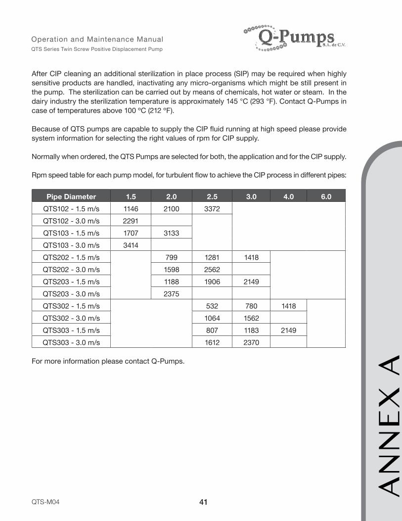
After CIP cleaning an additional sterilization in place process (SIP) may be required when highly sensitive products are handled, inactivating any micro-organisms which might be still present in the pump. The sterilization can be carried out by means of chemicals, hot water or steam. In the dairy industry the sterilization temperature is approximately 145 °C (293 °F). Contact Q-Pumps in case of temperatures above 100 ºC (212 ºF). Because of QTS pumps are capable to supply the CIP fluid running at high speed please provide system information for selecting the right values of rpm for CIP supply.
Normally when ordered, the QTS Pumps are selected for both, the application and for the CIP supply.
Rpm speed table for each pump model, for turbulent flow to achieve the CIP process in different pipes:
Pipe Diameter 1.5 2.0 2.5 3.0 4.0 6.0QTS102 - 1.5 m/s 1146 2100 3372QTS102 - 3.0 m/s 2291QTS103 - 1.5 m/s 1707 3133QTS103 - 3.0 m/s 3414QTS202 - 1.5 m/s 799 1281 1418QTS202 - 3.0 m/s 1598 2562QTS203 - 1.5 m/s 1188 1906 2149QTS203 - 3.0 m/s 2375QTS302 - 1.5 m/s 532 780 1418QTS302 - 3.0 m/s 1064 1562QTS303 - 1.5 m/s 807 1183 2149QTS303 - 3.0 m/s 1612 2370
For more information please contact Q-Pumps.
AN
NE
X A
42
Operation and Maintenance Manual QTS Series Twin Screw Positive Displacement Pump
QTS-M04
AN
NE
X B
ANNEX B
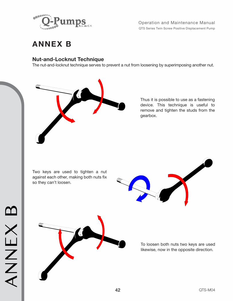
Nut-and-Locknut TechniqueThe nut-and-locknut technique serves to prevent a nut from loosening by superimposing another nut.
Thus it is possible to use as a fastening device. This technique is useful to remove and tighten the studs from the gearbox.
To loosen both nuts two keys are used likewise, now in the opposite direction.
Two keys are used to tighten a nut against each other, making both nuts fix so they can’t loosen.

43
Operation and Maintenance Manual QTS Series Twin Screw Positive Displacement Pump
QTS-M04

Acceso “A” #103, Fraccionamiento Industrial Jurica, Querétaro, Qro., México. C.P. 76130
Call: +52 (442) 218 4570 / 218 7400 Fax: +52 (442) 218 4577
www.qpumps.com
Operation and Maintenance Manual Positive Displacement Pump
QTS Series Twin Screw Pump