operation developments testing distributorless ignition systems
TRANSCRIPT

• Operation
• Developments
• Testing
Distributorless Ignition Systems

Distributorless Ignition Systems
The principles of operation are basically no different than those fordistributor equipped electronic ignition systems that began appearing on American automobiles in 1972.
There are 2 obvious differences:
• A DI system does not have a mechanical distributor.
• Most DI systems use one coil for every two spark plugs (however some systems have one coil per cylinder i.e. BMW).

Distributorless Ignition Systems
In operation the only major difference is that DI systems fireall of the engines spark plugs in ONE crankshaft revolution,whereas the old mechanical distributor type fires all plugs everyTWO crankshaft revolutions.
On all four stroke engines, equipped with or with out distributorsrequire TWO crankshaft revolutions (720° travel) for thecombustion to occur on each cylinder.
On engines with an even number of cylinders, combustion occursin half of the cylinders in the first revolution (360°) and in theother half in the second half of the revolution. Each cylinder thathas combustion in the first revolution has a companion cylinderthat fires 360° apart from it during the second revolution.

Layout
NGKNGK NGK NGK
ECU
Secondary
ECU+
Secondary
Primary
Primary

Distributorless Ignition Systems
In conventional systems the ignition coil is always connectedso that the secondary winding side will always be negative.This is done because the electrons readily tend to leave a hotsurface much more easily than a cold surface (the outerelectrode is much colder because it sinks heat into the cylinderhead).
Therefore 30% more energy is needed to fire a plug backwards(from the centre electrode).
As DIS produces high voltages (40 KV), this eliminates anydifficulty in firing the plugs.

+-
BATTERY
POINTS CONDENSER
15 4
1
IGNITIONCOIL
DISTRIBUTORCAP
IGNITIONSWITCH
STARTERMOTOR
NGK
+
_
Terminal 15 +
Terminal 1 -
Conventional System
_
NGKNGK NGK NGK
ECU
Secondary
ECU+
Secondary
Primary
Primary
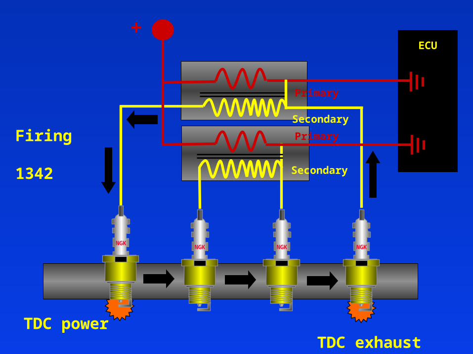
TDC power TDC exhaust
Firing
1342

NGKNGK
ECU
ECU+
Secondary
Primary
NGK NGK
Secondary
PrimaryFiring
1342

Distributorless Ignition Systems
As can been seen from the previous screens, the DI systemhas 2 secondary terminals that are connected to the sparkplugs of companion cylinders.
The coil fires both spark plugs at the same time every crankshaftrevolution. One of the spark plugs is called TRUE firing, becauseit occurs during the compression stroke and ignites the mixture.The other plug is called WASTED firing because it occurs on theexhaust stroke.

Distributorless Ignition Systems
Electron Flow - negative to positive
NGK NGK
Secondary
Primary
+_

NGK NGK
Secondary
PrimaryNGK NGK
+_
ELECTRON FLOW + TO -

Distributorless Ignition Systems
The arrows on the previous page show the direction of electron flow in the circuit when a spark occurs. It can be seenthat the electron path is from the left end (-) of the secondarywinding through the centre electrode and then through the headto the outer electrode of the right hand plug. After then jumpingover the gap to the centre electrode they flow to the right handend of the secondary (+) winding.
The series connection of the spark plugs causes one of the plugsto always fire in the reverse direction. The wasted firing needsvery little energy to bridge the gap due to the lack of pressure inthe cylinder, leaving more power for the cylinder under pressure.
Distributorless Ignition Systems
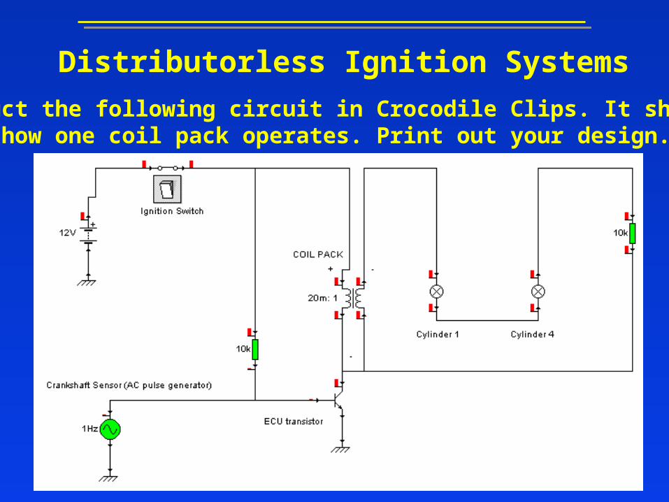
Construct the following circuit in Crocodile Clips. It shows verysimply how one coil pack operates. Print out your design.

Distributorless Ignition Systems
On DIS systems the ECU obtains crankshaft position by the means of an inductive sensor (many systems have a camshaftsensor as a failsafe). PERMANENT
MAGNET
SOFT IRON COREWINDING
Crankshaft Sensor
Camshaft Sensor

Distributorless Ignition Systems
The ECU utilises the KNOCKsensor to maximise performanceand economy.
Knock always occurs soon afterTDC and lasts between 3 to 15ms. Therefore the sensor is onlyexpected to send true knocksignals during a small window.
Within the window all the signalsare processed outside the window they are ignored.
Knock Sensor
Distributorless Ignition Systems
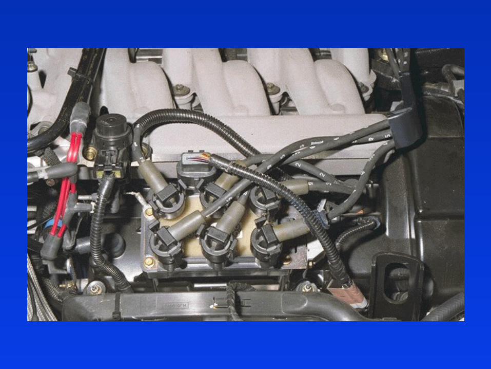
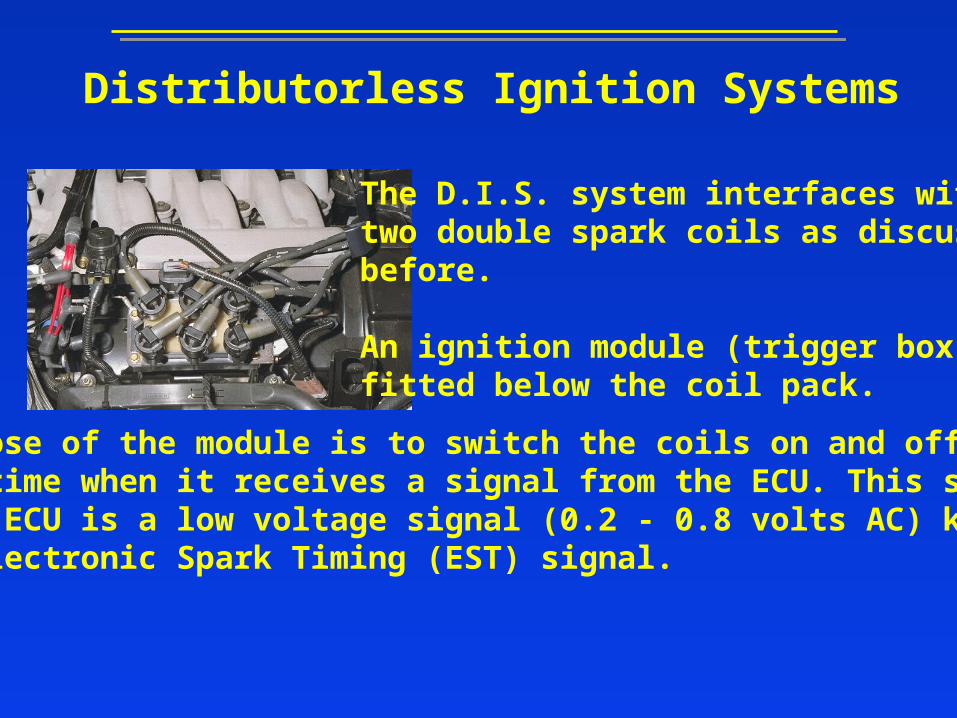
The D.I.S. system interfaces withtwo double spark coils as discussedbefore.
An ignition module (trigger box) isfitted below the coil pack.
The purpose of the module is to switch the coils on and off at the correct time when it receives a signal from the ECU. This signalfrom the ECU is a low voltage signal (0.2 - 0.8 volts AC) knownas the Electronic Spark Timing (EST) signal.

Distributorless Ignition Systems
There are 4 connections to the D.I.S module:
1. Ignition live
2. Earth
3. EST A (cyls. 1 + 4)
4. EST B (cyls. 2 + 3)
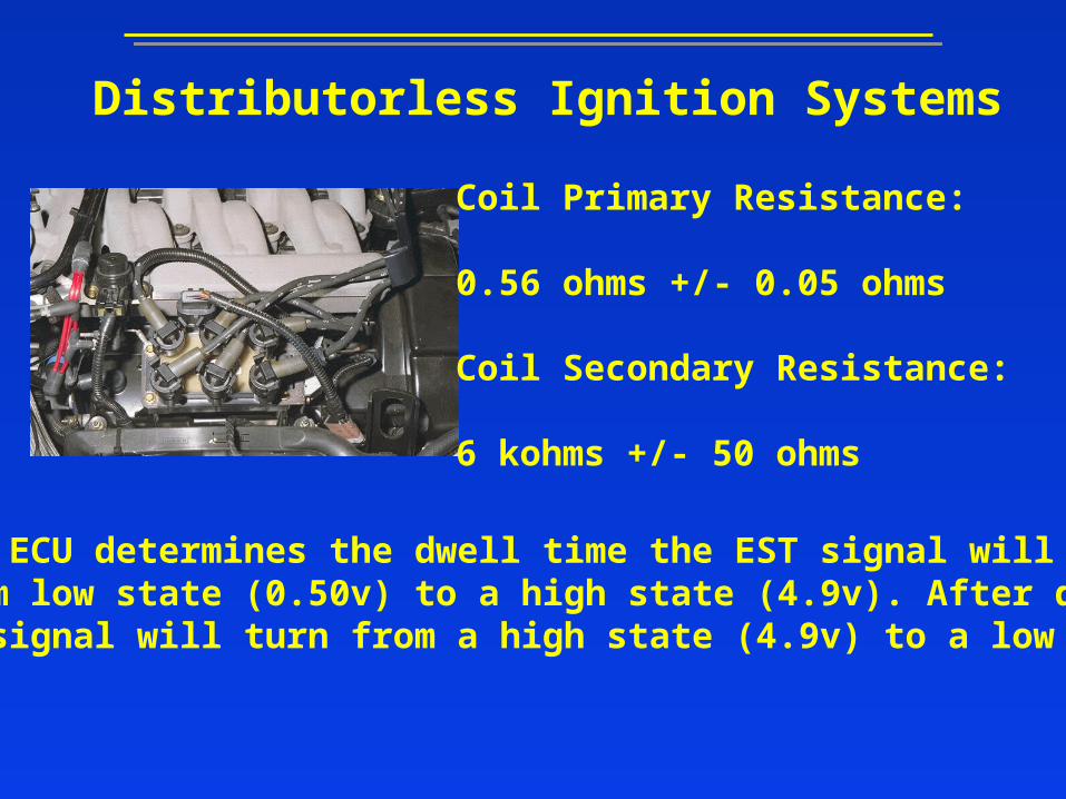
Distributorless Ignition Systems
Coil Primary Resistance:
0.56 ohms +/- 0.05 ohms
Coil Secondary Resistance:
6 kohms +/- 50 ohms
When the ECU determines the dwell time the EST signal willturn from low state (0.50v) to a high state (4.9v). After dwell timethe EST signal will turn from a high state (4.9v) to a low state(0.5v).

Distributorless Ignition Systems
The dwell algorithm of the ECUconsists of 2 different modes. Incrank mode the dwell time is basedupon a fixed number of engine anglesas well as battery voltage.
In the run mode the dwell time is based upon engine speed and batteryvoltage.
The transition from crank to run mode takes place at 400 rpm.

Systems now use1 coil per cylinderas in the BMW’s.
Distributorless Ignition Systems

Distributorless Ignition Systems
Tasks
1. When did electronic ignition systems first start appearing o vehicles?2. State the advantages of D.I. Systems.3. State the major differences of D.I. Systems?4. Draw and label a simple D.I. System.5. What charge is the secondary winding and why?6. How much energy is needed to fire the spark backwards?7. How much voltage does a D.I. System produce?8. What is meant by the terms Wasted and True firing?9. Describe the electron flow in a D.I. Circuit?10. Discuss and produce test procedures on a D.I. System.