how outboard motor ignition systems work, part 3 ignition
TRANSCRIPT
How Outboard Motor Ignition Systems Work, Part 3 Ignition with No Battery: the Magic of the Magneto
OutboardIgnitionPart3 W. Mohat Rev. 3.0 May 25, 2018
The ignition systems in antique outboards are usually magneto systems, as opposed to
battery, points, and coil systems. (If you don’t remember how battery, points, and coil
ignition systems work, please go back and read Parts 1 and 2 of this article series.)
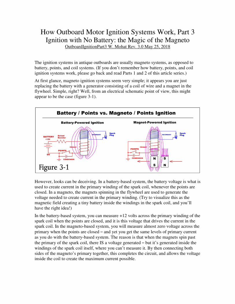
At first glance, magneto ignition systems seem very simple; it appears you are just
replacing the battery with a generator consisting of a coil of wire and a magnet in the
flywheel. Simple, right? Well, from an electrical schematic point of view, this might
appear to be the case (figure 3-1).
However, looks can be deceiving. In a battery-based system, the battery voltage is what is
used to create current in the primary winding of the spark coil, whenever the points are
closed. In a magneto, the magnets spinning in the flywheel are used to generate the
voltage needed to create current in the primary winding. (Try to visualize this as the
magnetic field creating a tiny battery inside the windings in the spark coil, and you’ll
have the right idea!)
In the battery-based system, you can measure +12 volts across the primary winding of the
spark coil when the points are closed, and it is this voltage that drives the current in the
spark coil. In the magneto-based system, you will measure almost zero voltage across the
primary when the points are closed – and yet you get the same levels of primary current
as you do with the battery-based system. The reason is that when the magnets spin past
the primary of the spark coil, there IS a voltage generated – but it’s generated inside the
windings of the spark coil itself, where you can’t measure it. By then connecting both
sides of the magneto’s primary together, this completes the circuit, and allows the voltage
inside the coil to create the maximum current possible.
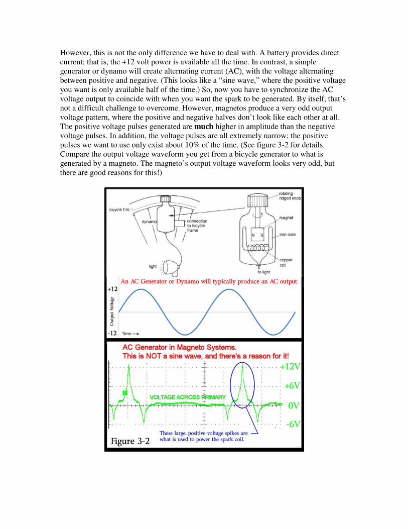
However, this is not the only difference we have to deal with. A battery provides direct
current; that is, the +12 volt power is available all the time. In contrast, a simple
generator or dynamo will create alternating current (AC), with the voltage alternating
between positive and negative. (This looks like a “sine wave,” where the positive voltage
you want is only available half of the time.) So, now you have to synchronize the AC
voltage output to coincide with when you want the spark to be generated. By itself, that’s
not a difficult challenge to overcome. However, magnetos produce a very odd output
voltage pattern, where the positive and negative halves don’t look like each other at all.
The positive voltage pulses generated are much higher in amplitude than the negative
voltage pulses. In addition, the voltage pulses are all extremely narrow; the positive
pulses we want to use only exist about 10% of the time. (See figure 3-2 for details.
Compare the output voltage waveform you get from a bicycle generator to what is
generated by a magneto. The magneto’s output voltage waveform looks very odd, but
there are good reasons for this!)
So, why do magnetos produce such an odd output voltage waveform? Well, here are the
reasons:
1) Magnetos were designed before solid-state diodes were invented. Back in the
1920s and 1930s, only AC voltages could be easily generated. (Well, you
COULD use a commutator and brushes system to give you only positive voltage
pulses, creating a DC generator, but commutators and brushes are expensive to
produce and a serious maintenance problem. Magnetos, especially in cheap
devices like lawn mowers and chain saws, have to be inexpensive and very
reliable. So, they have to deal with the AC voltage somehow.)
2) The magneto only uses the positive voltage pulses to create spark. The negative
output pulses are not used (or worse, they can interfere with the positive voltage
that we do want to use, so negative voltage output must be minimized if possible).
Refer back to figure 3-2 to see which portion of the magneto’s output voltage is
actually used to create the spark. (Key point: this picture of the AC voltage
created by the magneto is with the magneto’s generator not connected to any load.
You can see this if you disconnect the points and measure the AC voltage with no
load. When the points are functioning, you will not be able to see this voltage
across the magneto’s primary winding).
3) We want the positive voltage generated to be at the maximum level possible, at
exactly the time when the spark needs to be generated. When spark is not being
generated, the voltage is of no use to us so magnetos are designed in such a way
that they concentrate the positive voltage generated into a narrow, tall “spike” of
voltage, to maximize the energy possible right at the exact instant when the coil
needs to produce a spark. At the same time, negative voltage spikes are
minimized as much as possible, so they won’t interfere with the positive voltages
that we want to use.
And now for the two really big questions: First, how is this odd waveform created, and
second, how is it used to drive the spark coil? The “overview” answer to the first question
is that the armature core in the spark coil and the pole pieces on the magnet(s) in the
flywheel are specifically designed to produce this odd waveform. (“Poles” on magnets
and armatures are pieces of metal from which the lines of magnetic force are directed.)
If you look closely at the magneto in an outboard motor, you will find that there are more
magnets in the flywheel and poles in the armature cores than would seem to be necessary.
Johnson and Evinrude magnetos have two magnets in the flywheel, and three poles in the
armatures. (Refer to figure 3-4 for details.) Other systems may have three magnets in the
flywheel and two poles in the armatures. It is this difference between the number of poles
in the magnets and in the armature cores that is responsible for the creation of this odd
waveform, with two small negative voltage pulses around every large, positive voltage
pulse that is generated.
The “overview” answer to the second question is that when the output voltage is positive
and the points are closed, the circuit is completed and current is driven through the
primary winding in the magneto’s primary coil. This appears identical to the battery,
points, and coil based systems except that the “battery” here is voltage generated inside
the coil (where you can’t measure it) instead of being provided by an external battery,
where it’s easy to measure the voltage across the coil.
Now, to understand exactly how magnetos produce this output power waveform, it’s
necessary to first understand the basics of magnets, inductors, and transformers along
with how a battery, points, and coil ignition system works (if you have not already done
it, go back and review Parts 1 and 2).
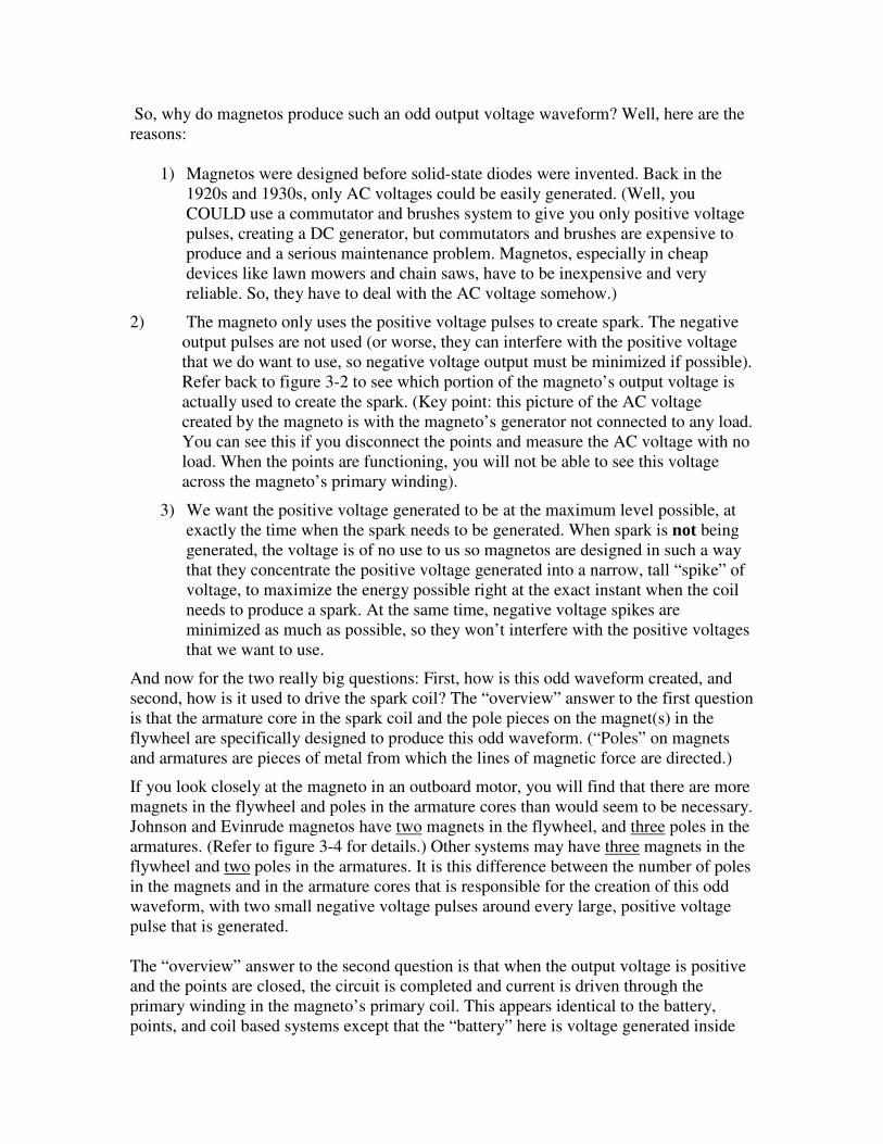
Faraday’s Law states that if you apply a voltage to a coil of wire, current will start to
flow. As this current increases, it will create a magnetic field around the coil (forming an
electromagnet). As the field increases in strength, it increases in size, causing the field to
appear to move. However, the opposite is also true: if you take a magnet (with the
magnetic field that surrounds it), and you move it past a coil of wire, then a voltage will
be created in that coil of wire. If that voltage is connected to a load of some sort, current
will flow (figure 3-3). It is the MOVEMENT of magnetic fields that creates voltage!
Also according to Faraday’s Law, the faster the rate of change in the magnetic field, the
larger the output voltage you will get; if the field changes VERY quickly, you can create
very high voltages in the coil windings. (Remember the bicycle generator? The faster you
pedal, the faster the generator spins and the brighter your bicycle’s headlight will shine
because of the increased output voltage.)
Always remember that in a magneto, the magnetic field applied to the coil’s primary
winding must be changing in size (or appearing to move) in order for any output voltage
(and, hence, current) to be generated. If the magnetic field is not changing (specifically, if
there is no magnetic field present, or if the magnetic field is at some maximum value but
is NOT increasing or decreasing in strength,) then no output voltage will be generated.
This is an important concept, and is absolutely key to understanding how a magneto
generates that odd output waveform.
So, now that we have reviewed the basic principles, let’s see how magnetos use them to
create their rather odd AC voltage output. We’ll start by looking at the Johnson/Evinrude
3-pole armature system, since it’s a little easier to explain. NOTE: In the figures that
follow, the points will be held open, so the voltage generated will not be affected by the
spark coil’s normal operation. For now, we just want to visualize how a magneto
functions as an AC generator. Note also in these figures that the cam, which normally
operates the points, is not shown because that’s not important right now. And finally, the
piston in the engine is at top dead center (TDC) when the magnets are just past the 12
o’clock (0 degrees) position in these figures.
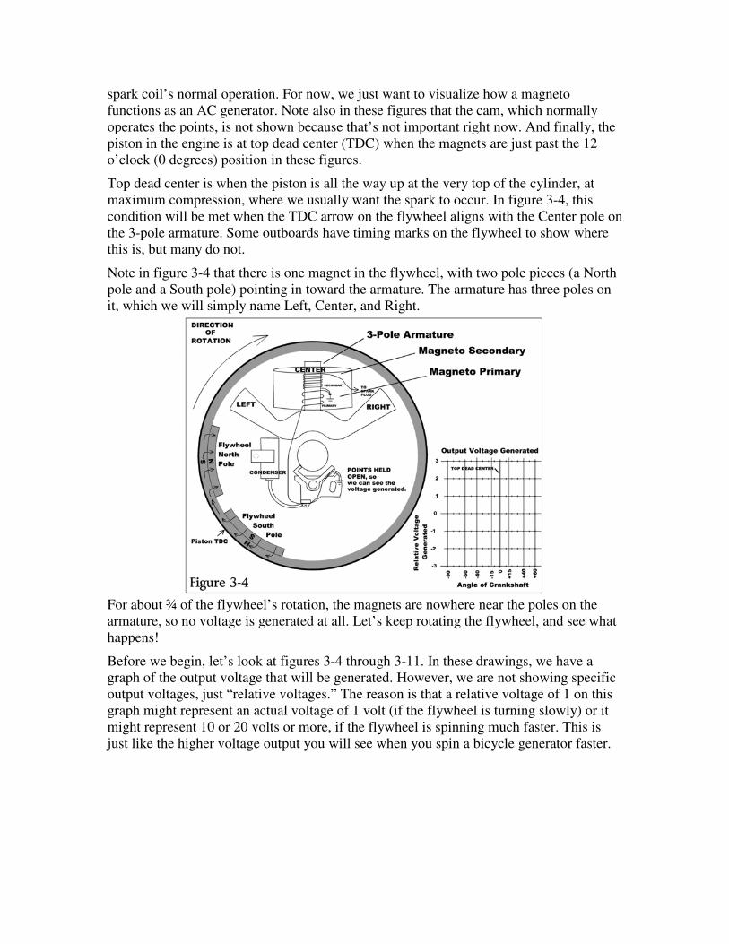
Top dead center is when the piston is all the way up at the very top of the cylinder, at
maximum compression, where we usually want the spark to occur. In figure 3-4, this
condition will be met when the TDC arrow on the flywheel aligns with the Center pole on
the 3-pole armature. Some outboards have timing marks on the flywheel to show where
this is, but many do not.
Note in figure 3-4 that there is one magnet in the flywheel, with two pole pieces (a North
pole and a South pole) pointing in toward the armature. The armature has three poles on
it, which we will simply name Left, Center, and Right.
For about ¾ of the flywheel’s rotation, the magnets are nowhere near the poles on the
armature, so no voltage is generated at all. Let’s keep rotating the flywheel, and see what
happens!
Before we begin, let’s look at figures 3-4 through 3-11. In these drawings, we have a
graph of the output voltage that will be generated. However, we are not showing specific
output voltages, just “relative voltages.” The reason is that a relative voltage of 1 on this
graph might represent an actual voltage of 1 volt (if the flywheel is turning slowly) or it
might represent 10 or 20 volts or more, if the flywheel is spinning much faster. This is
just like the higher voltage output you will see when you spin a bicycle generator faster.
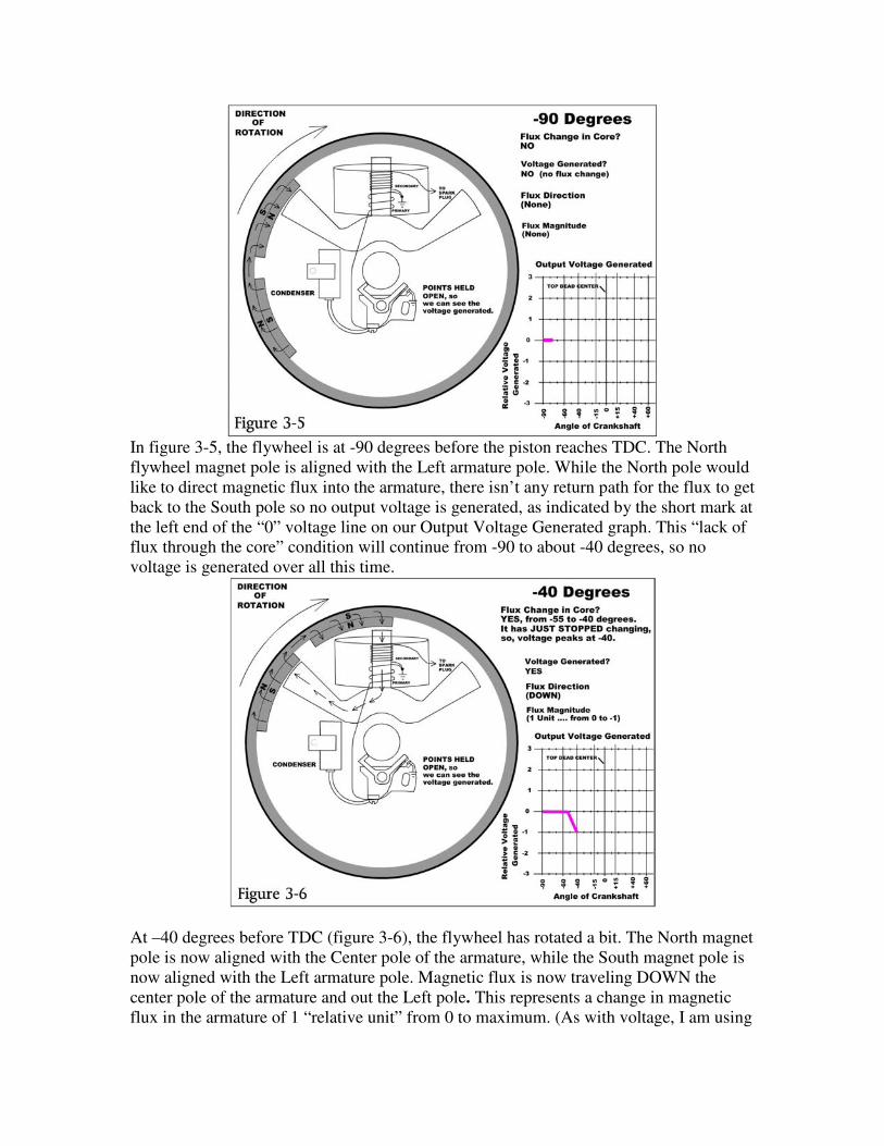
In figure 3-5, the flywheel is at -90 degrees before the piston reaches TDC. The North
flywheel magnet pole is aligned with the Left armature pole. While the North pole would
like to direct magnetic flux into the armature, there isn’t any return path for the flux to get
back to the South pole so no output voltage is generated, as indicated by the short mark at
the left end of the “0” voltage line on our Output Voltage Generated graph. This “lack of
flux through the core” condition will continue from -90 to about -40 degrees, so no
voltage is generated over all this time.
At –40 degrees before TDC (figure 3-6), the flywheel has rotated a bit. The North magnet
pole is now aligned with the Center pole of the armature, while the South magnet pole is
now aligned with the Left armature pole. Magnetic flux is now traveling DOWN the
center pole of the armature and out the Left pole. This represents a change in magnetic
flux in the armature of 1 “relative unit” from 0 to maximum. (As with voltage, I am using
“relative units” because we don’t know the strength of the magnets, so I can’t indicate a
specific magnetic field strength in terms of gauss per square inch. The actual field
strength doesn’t matter for this discussion of basic principles.)
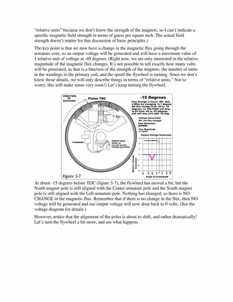
The key point is that we now have a change in the magnetic flux going through the
armature core, so an output voltage will be generated and will have a maximum value of
1 relative unit of voltage at -40 degrees. (Right now, we are only interested in the relative
magnitude of the magnetic flux changes. It’s not possible to tell exactly how many volts
will be generated, as that is a function of the strength of the magnets, the number of turns
in the windings in the primary coil, and the speed the flywheel is turning. Since we don’t
know those details, we will only describe things in terms of “relative units.” Not to
worry, this will make sense very soon!) Let’s keep turning the flywheel.
At about -15 degrees before TDC (figure 3-7), the flywheel has moved a bit, but the
North magnet pole is still aligned with the Center armature pole and the South magnet
pole is still aligned with the Left armature pole. Nothing has changed, so there is NO
CHANGE in the magnetic flux. Remember that if there is no change in the flux, then NO
voltage will be generated and our output voltage will now drop back to 0 volts. (See the
voltage diagram for details.)
However, notice that the alignment of the poles is about to shift, and rather dramatically!
Let’s turn the flywheel a bit more, and see what happens.
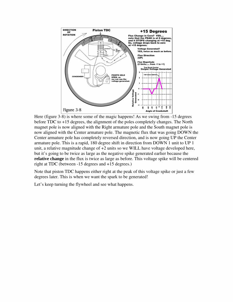
Here (figure 3-8) is where some of the magic happens! As we swing from -15 degrees
before TDC to +15 degrees, the alignment of the poles completely changes. The North
magnet pole is now aligned with the Right armature pole and the South magnet pole is
now aligned with the Center armature pole. The magnetic flux that was going DOWN the
Center armature pole has completely reversed direction, and is now going UP the Center
armature pole. This is a rapid, 180 degree shift in direction from DOWN 1 unit to UP 1
unit, a relative magnitude change of +2 units so we WILL have voltage developed here,
but it’s going to be twice as large as the negative spike generated earlier because the
relative change in the flux is twice as large as before. This voltage spike will be centered
right at TDC (between -15 degrees and +15 degrees.)
Note that piston TDC happens either right at the peak of this voltage spike or just a few
degrees later. This is when we want the spark to be generated!
Let’s keep turning the flywheel and see what happens.
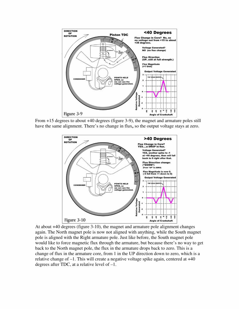
From +15 degrees to about +40 degrees (figure 3-9), the magnet and armature poles still
have the same alignment. There’s no change in flux, so the output voltage stays at zero.
At about +40 degrees (figure 3-10), the magnet and armature pole alignment changes
again. The North magnet pole is now not aligned with anything, while the South magnet
pole is aligned with the Right armature pole. Just like before, the South magnet pole
would like to force magnetic flux through the armature, but because there’s no way to get
back to the North magnet pole, the flux in the armature drops back to zero. This is a
change of flux in the armature core, from 1 in the UP direction down to zero, which is a
relative change of –1. This will create a negative voltage spike again, centered at +40
degrees after TDC, at a relative level of –1.
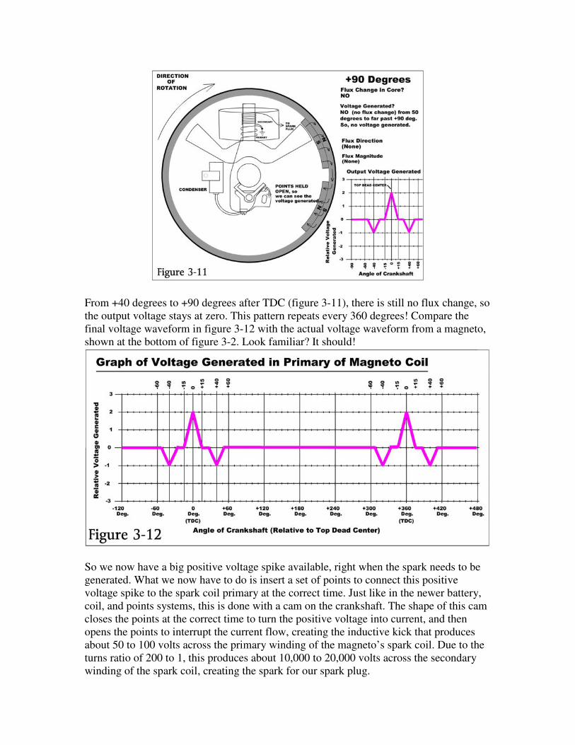
From +40 degrees to +90 degrees after TDC (figure 3-11), there is still no flux change, so
the output voltage stays at zero. This pattern repeats every 360 degrees! Compare the
final voltage waveform in figure 3-12 with the actual voltage waveform from a magneto,
shown at the bottom of figure 3-2. Look familiar? It should!
So we now have a big positive voltage spike available, right when the spark needs to be
generated. What we now have to do is insert a set of points to connect this positive
voltage spike to the spark coil primary at the correct time. Just like in the newer battery,
coil, and points systems, this is done with a cam on the crankshaft. The shape of this cam
closes the points at the correct time to turn the positive voltage into current, and then
opens the points to interrupt the current flow, creating the inductive kick that produces
about 50 to 100 volts across the primary winding of the magneto’s spark coil. Due to the
turns ratio of 200 to 1, this produces about 10,000 to 20,000 volts across the secondary
winding of the spark coil, creating the spark for our spark plug.
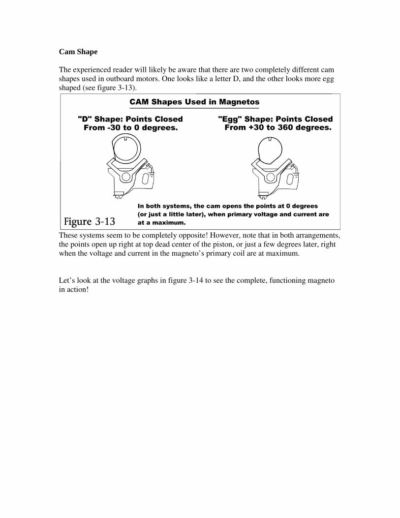
Cam Shape
The experienced reader will likely be aware that there are two completely different cam
shapes used in outboard motors. One looks like a letter D, and the other looks more egg
shaped (see figure 3-13).
These systems seem to be completely opposite! However, note that in both arrangements,
the points open up right at top dead center of the piston, or just a few degrees later, right
when the voltage and current in the magneto’s primary coil are at maximum.
Let’s look at the voltage graphs in figure 3-14 to see the complete, functioning magneto
in action!
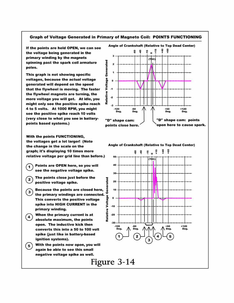
A note about figure 3-14: Please remember that these graphs are showing relative
voltage, not actual voltage. This is because all of these voltages will depend on how fast
your motor (and flywheel) are turning. At idle, you might only see a few volts across the
primary winding. At 1,000 RPM, you might see 10 volts (just like with a battery-points
based ignition system). At 5,000 RPM, you’ll see much higher voltages. (Remember, the
faster an engine runs, the stronger the spark generated by a magneto. This is why many
racing engines today still use magnetos.)
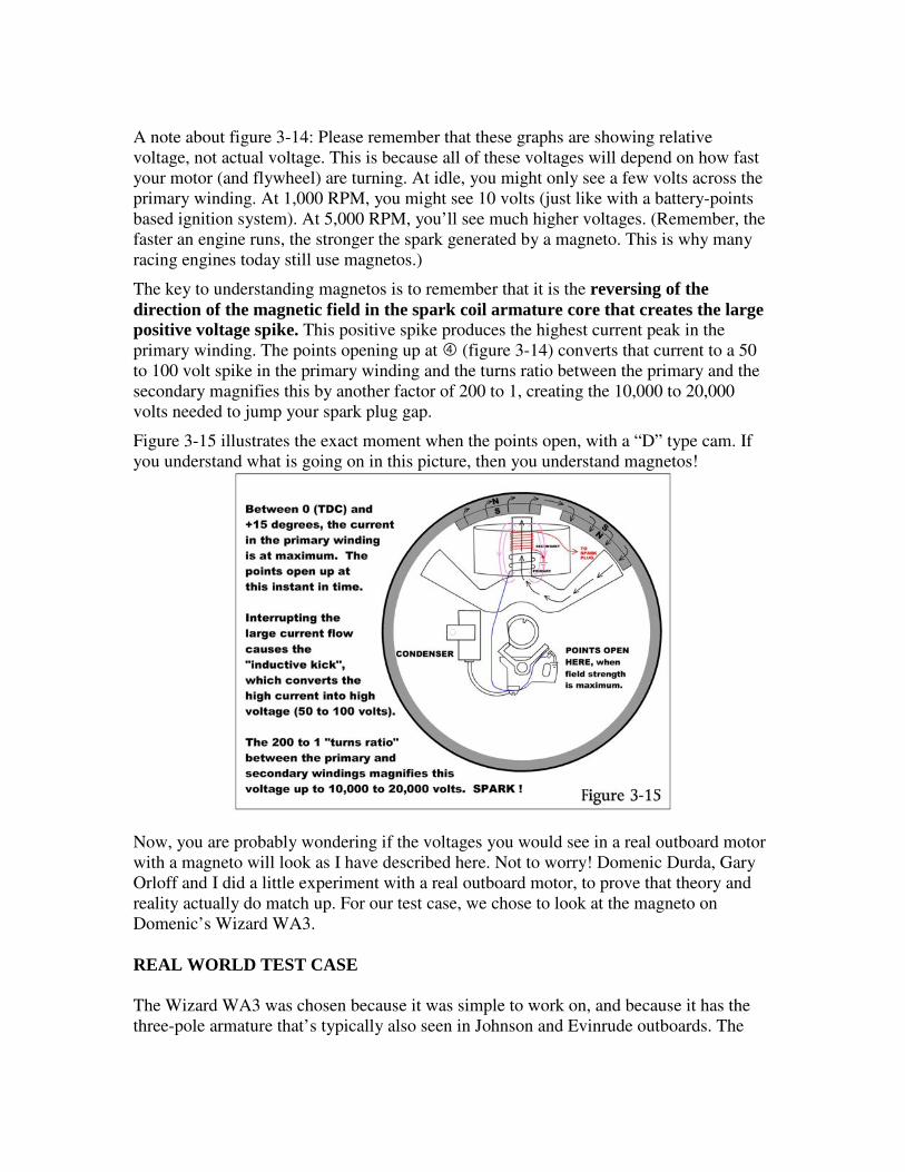
The key to understanding magnetos is to remember that it is the reversing of the
direction of the magnetic field in the spark coil armature core that creates the large
positive voltage spike. This positive spike produces the highest current peak in the
primary winding. The points opening up at (figure 3-14) converts that current to a 50
to 100 volt spike in the primary winding and the turns ratio between the primary and the
secondary magnifies this by another factor of 200 to 1, creating the 10,000 to 20,000
volts needed to jump your spark plug gap.
Figure 3-15 illustrates the exact moment when the points open, with a “D” type cam. If
you understand what is going on in this picture, then you understand magnetos!
Now, you are probably wondering if the voltages you would see in a real outboard motor
with a magneto will look as I have described here. Not to worry! Domenic Durda, Gary
Orloff and I did a little experiment with a real outboard motor, to prove that theory and
reality actually do match up. For our test case, we chose to look at the magneto on
Domenic’s Wizard WA3.
REAL WORLD TEST CASE
The Wizard WA3 was chosen because it was simple to work on, and because it has the
three-pole armature that’s typically also seen in Johnson and Evinrude outboards. The
three-pole system is a bit easier to understand than the two-pole armature system, so
we’ll look at that system first.
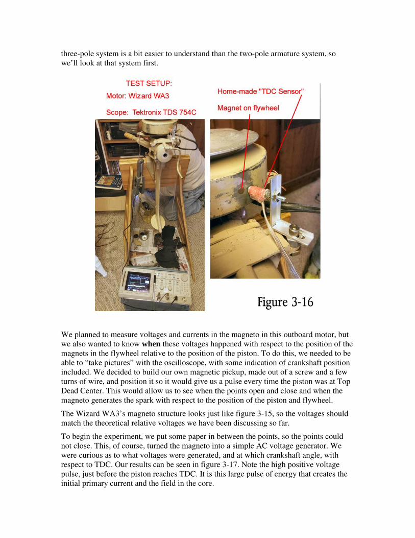
We planned to measure voltages and currents in the magneto in this outboard motor, but
we also wanted to know when these voltages happened with respect to the position of the
magnets in the flywheel relative to the position of the piston. To do this, we needed to be
able to “take pictures” with the oscilloscope, with some indication of crankshaft position
included. We decided to build our own magnetic pickup, made out of a screw and a few
turns of wire, and position it so it would give us a pulse every time the piston was at Top
Dead Center. This would allow us to see when the points open and close and when the
magneto generates the spark with respect to the position of the piston and flywheel.
The Wizard WA3’s magneto structure looks just like figure 3-15, so the voltages should
match the theoretical relative voltages we have been discussing so far.
To begin the experiment, we put some paper in between the points, so the points could
not close. This, of course, turned the magneto into a simple AC voltage generator. We
were curious as to what voltages were generated, and at which crankshaft angle, with
respect to TDC. Our results can be seen in figure 3-17. Note the high positive voltage
pulse, just before the piston reaches TDC. It is this large pulse of energy that creates the
initial primary current and the field in the core.
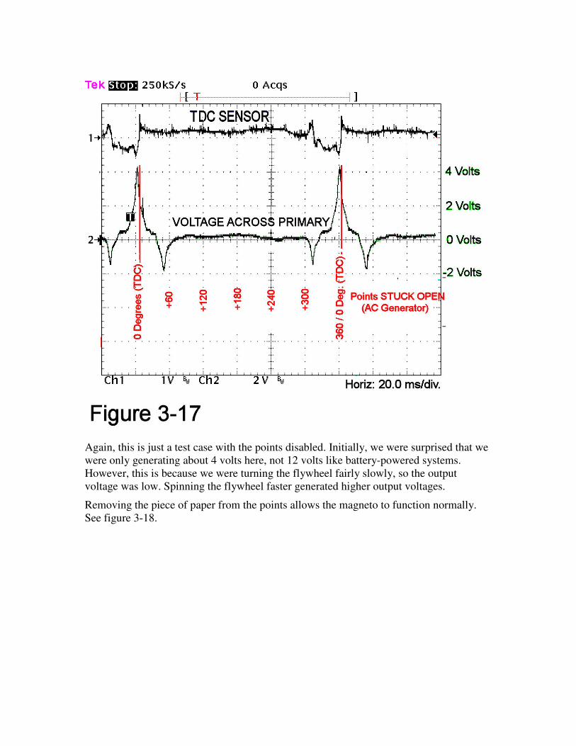
Again, this is just a test case with the points disabled. Initially, we were surprised that we
were only generating about 4 volts here, not 12 volts like battery-powered systems.
However, this is because we were turning the flywheel fairly slowly, so the output
voltage was low. Spinning the flywheel faster generated higher output voltages.
Removing the piece of paper from the points allows the magneto to function normally.
See figure 3-18.
(Note that on this Wizard motor, at mid-throttle the spark fires exactly when the piston is
at TDC.)
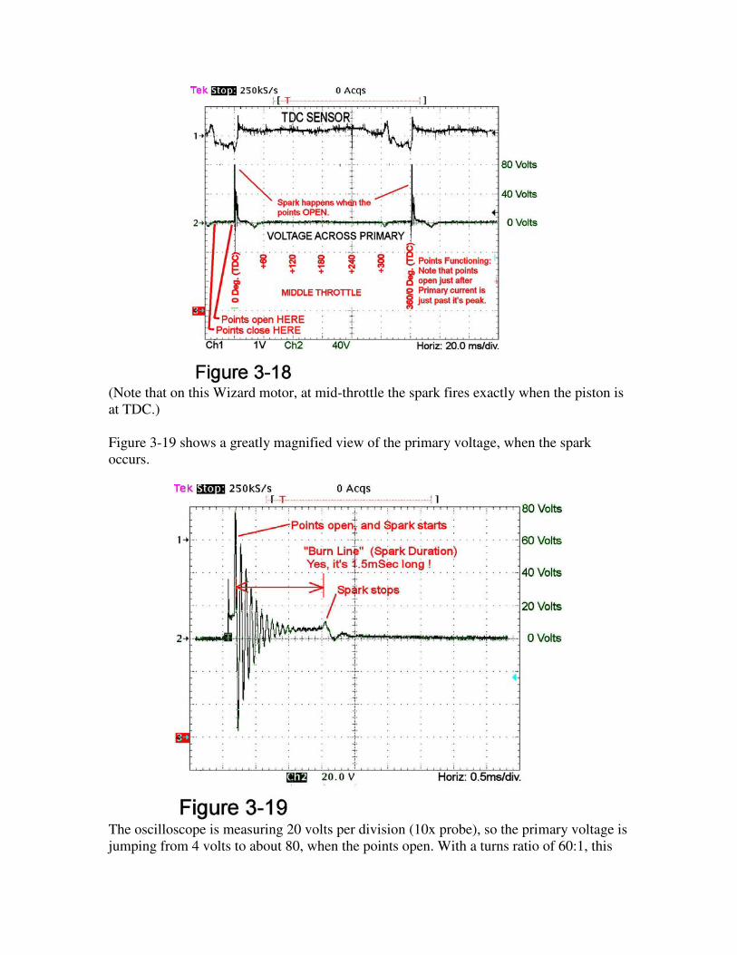
Figure 3-19 shows a greatly magnified view of the primary voltage, when the spark
occurs.
The oscilloscope is measuring 20 volts per division (10x probe), so the primary voltage is
jumping from 4 volts to about 80, when the points open. With a turns ratio of 60:1, this
means the Wizard’s spark plug is firing at about 4,800 volts. The spark voltage instantly
drops to about 600 volts (still jumping across the ionized gas in the spark plug gap) and
this continues for 1.5 milliseconds. While these voltages seem low, it’s because we had
the spark plug firing in open air. (The engine is a lot easier to spin when the spark plugs
are not in the cylinders!) When the spark plugs are installed in the engine, the denser
air/fuel mixture is harder to penetrate, requiring higher voltages to jump the gap. In all
ignition systems, the inductive kick will cause the spark coil voltage to rise as high as
necessary, until the voltage jumps across the spark gap.
Note in figure 3-19 that the arc continues for a duration of 1.5 milliseconds. That is what
makes this a really hot spark!
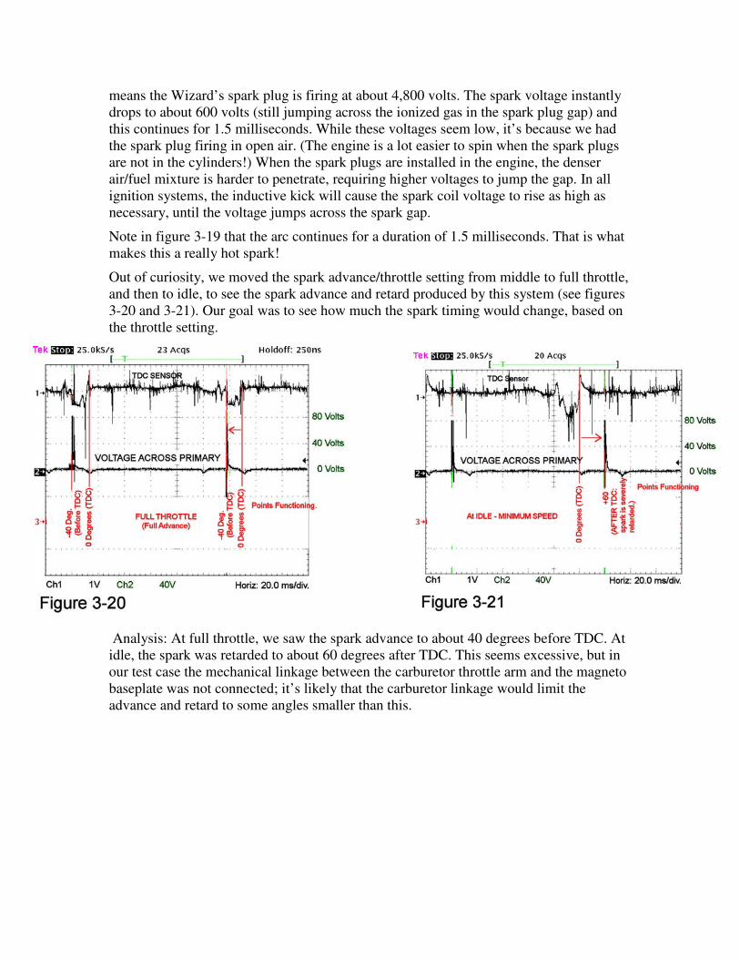
Out of curiosity, we moved the spark advance/throttle setting from middle to full throttle,
and then to idle, to see the spark advance and retard produced by this system (see figures
3-20 and 3-21). Our goal was to see how much the spark timing would change, based on
the throttle setting.
Analysis: At full throttle, we saw the spark advance to about 40 degrees before TDC. At
idle, the spark was retarded to about 60 degrees after TDC. This seems excessive, but in
our test case the mechanical linkage between the carburetor throttle arm and the magneto
baseplate was not connected; it’s likely that the carburetor linkage would limit the
advance and retard to some angles smaller than this.
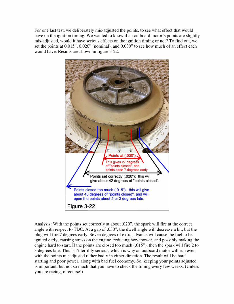
For one last test, we deliberately mis-adjusted the points, to see what effect that would
have on the ignition timing. We wanted to know if an outboard motor’s points are slightly
mis-adjusted, would it have serious effects on the ignition timing or not? To find out, we
set the points at 0.015”, 0.020” (nominal), and 0.030” to see how much of an effect each
would have. Results are shown in figure 3-22.
Analysis: With the points set correctly at about .020”, the spark will fire at the correct
angle with respect to TDC. At a gap of .030”, the dwell angle will decrease a bit, but the
plug will fire 7 degrees early. Seven degrees of extra advance will cause the fuel to be
ignited early, causing stress on the engine, reducing horsepower, and possibly making the
engine hard to start. If the points are closed too much (.015”), then the spark will fire 2 to
3 degrees late. This isn’t terribly serious, which is why an outboard motor will run even
with the points misadjusted rather badly in either direction. The result will be hard
starting and poor power, along with bad fuel economy. So, keeping your points adjusted
is important, but not so much that you have to check the timing every few weeks. (Unless
you are racing, of course!)
Two related topics of interest:
1) MAGNETS. Modern magnets (Alnico, Samarium Cobalt and Neodymium) hold their
magnetic strength for many years. Typically, they lose less than 10% of their strength
over 100 years – but this is not true of the magnets used in antique outboards. Back in
the 1930s and 1940s, most outboards were built with steel magnets. These magnets
lose about 1% of their strength every year. After 50 years or more, their strength can
be very low, often not enough for the magneto to work properly. Your coils and
points may be fine, but you won’t get any spark if the magnets in your flywheel are
too weak.
There are magnetizers available that can re-magnetize the weak magnets in an old
flywheel and get them back up to full strength. Some old repair shops and some
members of the Antique Outboard Motor Club still own some of these old
magnetizers.
2) THE DIFFERENT TYPES OF CAMS. This article discussed D-shaped cams in detail.
They are only closed for about 30 out of 360 degrees of the flywheel rotation. The
points are open when the negative voltage pulses occur, so these pulses can be seen
with an oscilloscope if you look for them. (Think of this as a “mechanical rectifier,” if
you wish, because that’s exactly what it is doing!)
In contrast, egg-shaped cams are closed for 330 out of the 360 degrees. Notice that they
are closed during the negative voltage spikes, so they send these negative voltage
pulses to the spark coil primary along with the desired positive pulses. When the
points controlled by an egg-shaped cam are closed during the negative voltage pulses,
they get current going in the wrong direction in the spark coil’s primary windings.
The higher positive voltage pulse then has to stop, then reverse the direction of the
current flow in the primary winding before the spark can be generated. This wastes a
bit of energy, which isn’t the most efficient way to create spark with a magneto.
From an electrical point of view, D shaped cams allow the magneto to create a hotter
spark with weaker magnets, while running the coil cooler. Egg-shaped cams are less
efficient, electrically speaking, but they experience less wear at the point of contact
between the points and the cam. There are strengths and weaknesses with each of the
different cam systems, but both of these cams open the points at the exact same time,
when the positive voltage is at its peak value, or just a few degrees later.
And a final note:
This article only discussed the three-pole armature system in detail. The three-pole
magnet, two-pole armature style of magneto also produces the same odd “W” shaped
voltage waveform, but its principle of operation would take another 10 pages to explain.
All you need to know is when the direction of the flux in the armature core changes
direction, the spark should be generated at that point or just a few degrees later.