operation manual - labnics before use thank you for choosing labnics equipment products. please read...
TRANSCRIPT

SHAKING INCUBATOR
Operation Manual
Model : LBSI - 100 A
Labnics Equipment

S. No. Content Pg. No.
1.1 Before Use 1
1.2 Safety Precaution 1
1.2.1 Power Connection 1
1.2.2 Installation 1
1.2.3 Operation 2
1.2.4 Maintenance 2
1.3 Product Feature 3
1.4 Specification 4
1.5 Parts and Functions 5
1.5.1 Main Controller 5
1.5.2 Main controller parts and description 5-8
1.6 Operation 9-11
1.7 Frequently Asked Question 12
1.8 Trouble Shooting 12
1.9 Setting Factory Parameters 13-15
1.10 Inspection Log For Shaking Incubator 16
1.11 Maintenance and Service Check List 17
1.12 Limited Warranty 18
1.13 Service Report 19
Table of Content

1.1 Before Use
Thank you for choosing Labnics Equipment Products.
Please read this operation manual carefully before use for your safety and optimum operating
performance.
If you have any question, please contact sales representative or service department.
1.2 Safety Precaution
This manual contains important operating and safety information. You must carefully read and
understand the contents of this manual prior to the use of this equipment.
Warning
To alert against any possible personal injuries.
Caution
To alert against any possible damage to the equipment.
1.2.1. Power Connection
Caution
1. Your Shaking Incubator is designed for 110VAC 60Hz 1P or 220VAC 50Hz
2. Check electrical requirement on the name plate before use.
3. Connect to receptacle with ground connection.
4. Be sure to connect on sufficient electrical current receptacle.
1.2.2. Installation
Caution
1. Do not use in high humid environment
! May cause Electrical leakage
! Corrosion may occur
2. Do not use in high temperature environment or beside instruments that generate heat.
3. Place on flat, rigid and leveled surface.
- 1 -

1.2.3. Operation
Warning
1. Hot surface or parts may cause serious injury.
2. Moving parts in the chamber may cause serious injury.
3. Do not put volatile, flammable and explosive material inside of chamber
4. Do not put volatile, flammable and explosive material nearby the instrument
5. Moving parts may cause serious injury during operation. Be sure to put or withdraw samples or
containers in the rack after shaking motion is completely stop.
Caution
1. Be careful not to spill liquid on the control panel
2. When you place samples or containers on the flask holders or spring rack, be sure to balance
the weight .
Imbalance may cause damage on motor or shaking mechanism and noise or
vibration may occur.
1.2.4. Maintenance
Caution
1. Do not pour water or any liquid when you clean up chamber.
2. Do not use concentrated organic solvents for cleaning chamber surface.
3. Do not modify or alter electrical circuit or hardware.
- 2 -
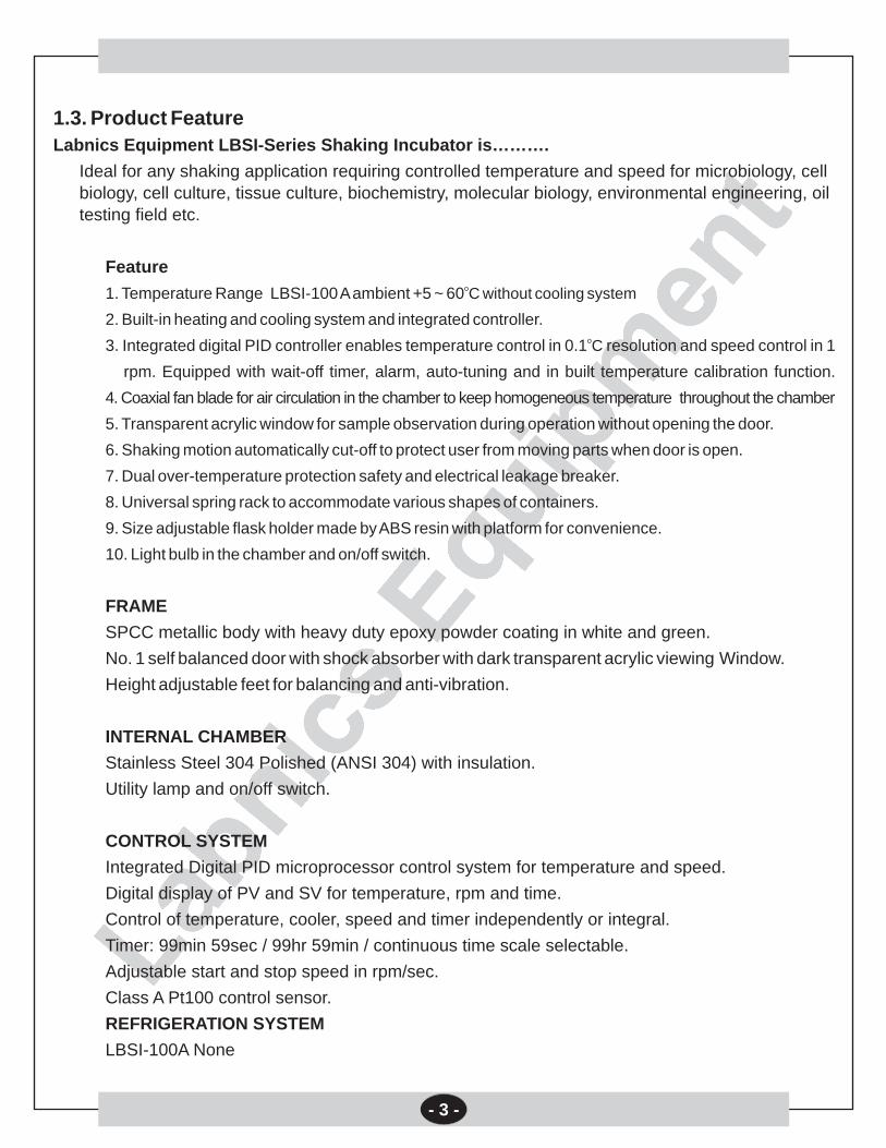
1.3. Product Feature
Labnics Equipment LBSI-Series Shaking Incubator is……….
Ideal for any shaking application requiring controlled temperature and speed for microbiology, cell biology, cell culture, tissue culture, biochemistry, molecular biology, environmental engineering, oil testing field etc.
Feature
1. Temperature Range LBSI-100 A ambient +5 ~ 60
2. Built-in heating and cooling system and integrated controller.o3. Integrated digital PID controller enables temperature control in 0.1 C resolution and speed control in 1
rpm. Equipped with wait-off timer, alarm, auto-tuning and in built temperature calibration function.
4. Coaxial fan blade for air circulation in the chamber to keep homogeneous temperature throughout the chamber
5. Transparent acrylic window for sample observation during operation without opening the door.
6. Shaking motion automatically cut-off to protect user from moving parts when door is open.
7. Dual over-temperature protection safety and electrical leakage breaker.
8. Universal spring rack to accommodate various shapes of containers.
9. Size adjustable flask holder made by ABS resin with platform for convenience.
10. Light bulb in the chamber and on/off switch.
FRAME
SPCC metallic body with heavy duty epoxy powder coating in white and green.
No. 1 self balanced door with shock absorber with dark transparent acrylic viewing Window.
Height adjustable feet for balancing and anti-vibration.
INTERNAL CHAMBER
Stainless Steel 304 Polished (ANSI 304) with insulation.
Utility lamp and on/off switch.
CONTROL SYSTEM
Integrated Digital PID microprocessor control system for temperature and speed.
Digital display of PV and SV for temperature, rpm and time.
Control of temperature, cooler, speed and timer independently or integral.
Timer: 99min 59sec / 99hr 59min / continuous time scale selectable.
Adjustable start and stop speed in rpm/sec.
Class A Pt100 control sensor.
REFRIGERATION SYSTEM
LBSI-100A None
oC without cooling system
- 3 -

SAFETY
Shaking motion stops when door is open.
Adjustable over-temp. cut-off safety thermostat
Over current cut-off: Electrical leakage breaker.
ALARM SYSTEM
Audible and visual alarm system for;
* Over temperature
* Shaking motion failure
* Disconnection of sensor
Model LBSI-100A
Chamber Volume 115L
Temperature Heating Type Forced Convectiono oRange Ambient +5 C- 60 C without cooling system
o oAccuracy 0.1 C at 25 Co oUniformity 1.0 C at 25 C
Shaking Speed/ Stroke 60-300rpm/20mm orbital motion
Heater 400 watt
Control Main Controller Digital PID controller with timer and auto-tuning
Wait off Timer mm:ss/hh:mm/continuous selectable
Sensor Pt-100
Safety Device Temperature Hydraulic over temperature protection safety device
Electrical Electrical leakage breaker
Dimension (W x D x H)mm Chamber 550 x 585 x 360
Overall 765 x 640 x 770
Platform 500W x 510D
Refrigerator None
Material Internal Stainless steel 0.8T polished (SUS 304)
External Steel 1T with epoxy powder coating
Door Weight balanced door with transparent Acrylic Window 340 x 300nm
Utility Lamp 25 Watt crypton Lamp in chamber
Electrical Requirement 120VAC 60Hz 1P or 220VAC 50Hz 1P or 220VAC 60Hz 1P
Net Weight 80Kg
Shipping Weight 95Kg
Shipping Dimensions 950 x 750 x 1000 mm
Catalog No. 18150101
?
Descriptions Catalog No.
Universal Spring Rack 500 x 495 x 140 mm 18150111
Flask holder size adjustable from 50 ~ 100ml x 30 EA Maximum 18150112
Flask holder size adjustable from 200 ~ 300ml x 20 EA 18150113
Flask holder size adjustable from 500ml x 12 EA or 1000ml x 5 EA 18150114
1.4. Specifications
Optional Accessories
- 4 -

1.5. Parts and Functions
1.5.1. Main Controller
1.5.2. Main Controller Parts and descriptions
< DISPLAYS >
PV Digital LED Display
PRESENT TEMPERATURE
Displays present temperature in the chamber
SV Digital LED Display
Displays set value of temperature, rpm and time alternatively by
pressing INC button
Display mode indication lamp lit when SV displays temp. Rpm or
time accordingly.
- 5 -

RPM Button
Start and stop shaking. (Press to ON and press again to OFF)
COOL Button
LBSI-100A Shaking Incubator has no cooling system.
Button has no function.
MODE Button
Press to set temp. rpm and time.
Press to set factory parameters. (See how to set factory parameters on SETTING PARAMETER section)
< PILOT LAMPS> Display Mode Indication Lamp
SV pilot lamp lit when SV LED displays set temperature
RPM pilot lamp lit when SV LED displays set rpm
TIME pilot lamp lit when SV LED displays time
Operating Status Indication Lamp
Heater On: Turned on when controller give output to heater. ON
and OFF during PID control.
Heat: Turned on when heating starts by pressing HEAT button.
RPM: Turned on when shaking starts by pressing RPM button.
TIMER: Turned on when user set wait-off timer and timer
starts count down by press HEAT or RPM button.
COOL: Blinks when cooler stops.
Lit on when cooler is running.
< OPERATION BUTTONS >
HEAT BUTTON
Start and stop heating. (Press to ON and press again to OFF)
- 6 -
MODE

LEFT SHIFT Button
Press to shift cursor to left digit when setting temp. rpm or time.
AUTO-TUNING Function
Press and hold for 5 seconds to start auto-tuning
Your Shaking Incubator was auto-tuned and calibrated before shipment.
About Auto-Tuning
The temperature of your Shaking Incubator is controlled by precise PID Microprocessor controller.
Controller automatically calculate optimum operating parameters such as P, I, A and D value.
Auto-Tuning command enables to optimize temperature control.
When Auto-Tuning needed
Your Shaking Incubator is auto-tuned before shipment. You do not need to auto-tune again before use.
Auto-tune is necessary in case of
- Replacing heater (after replacing heater and check temperature stability. If temperature stability is ok, auto-tuning is not necessary)
- Replacing main controller (when you replace main controller, you have to auto-tune again)
How to start Auto-Tuning
- Input factory parameter as per instruction.o- Set temperature at 37 C for LBSI-100A.
- Set rpm at 60 rpm.
- Press HEAT and RPM button to start temperature and rpm control.
- Press and hold LEFT SHIFT BUTTON for 5 seconds.
- LED displays blink indicating auto-tuning is stars with beep sound.
- Wait for 30 minutes to finish auto-tuning.
- LED displays stop blinking with beep sound indicating auto-tuning is finished.
Shaking Incubator is auto-tuned again and ready to use.
- 7 -

RIGHT SHIFT Button
Press to shift cursor to right digit when setting temp. rpm or time.
INC Button
Increase values by 1 increment.
DSP Function
In normal display mode, press INC button to change display on SV LED display to shoe set temp. rpm or time alternatively.
SAFETY LAMP/AUTO-THERMAL CUT-OFF SAFETY
THERMOSTAT
Safety lamp turned on indicating current chamber temperature is higher than over temp. Cut-off setting.
Turn auto thermal cut-off safety thermostat to 20% higher than normal ooperating temperature. (Ex. Your operating temperature is 40 C, set
osafety thermostat at 60 C, if chamber temperature increase higher othan 60 C by any reason, thermostat automatically cut-off heater and
lamp is turned on.)
POWER SWITCH
Main Power Switch.
- 8 -

1.6. Operation
Before Operation
1) Check electrical requirement on the name plate before connecting.
2) Place your Shaking Incubator on the flat and level surface.
3) Remove packing material in the chamber.
4) Be sure to place shaking wire rack on the right position and well balanced.
5) Connect power plug in rear panel to wall mount receptacle.
Getting Started
1) Load sample containers on the Spring Wire Rack or Flask Holders.
2) Be careful sample containers are weight balanced symmetrically.
3) Turn the circuit breaker on located on the back. Turn the POWER switch on. The PV LED
READOUT displays current temperature of the chamber.
Setting Temperature, RPM and Time
You can change operating temperature, rpm and time by using
MODE button.
Setting mode changes as left figure.
Setting Temperature
1) Press MODE button to set temperature in normal display mode.
2) PV Digital LED displays " TEMP " and SV Digital LED displays
current SV temperature and prompt user input.
3) Press SHIFT button to move left or right digit.
4) Press INC button to increase or decrease value.
5) Press MODE button again to go RPM setting.
6) Press MODE button twice to go normal display mode.
o o(Illus. shown how to change operating temperature from 37.0 C to 40.0 C)
- 9 -
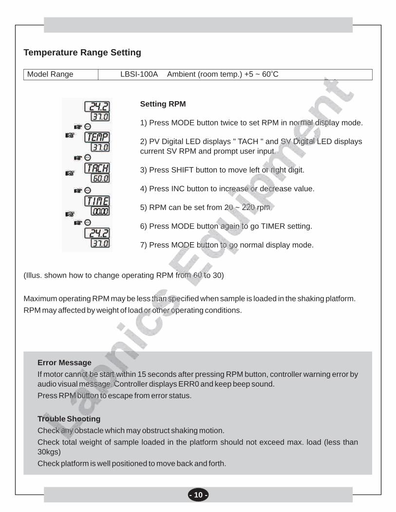
Temperature Range Setting
Setting RPM
1) Press MODE button twice to set RPM in normal display mode.
2) PV Digital LED displays " TACH " and SV Digital LED displays
current SV RPM and prompt user input.
3) Press SHIFT button to move left or right digit.
4) Press INC button to increase or decrease value.
5) RPM can be set from 20 ~ 220 rpm.
6) Press MODE button again to go TIMER setting.
7) Press MODE button to go normal display mode.
(Illus. shown how to change operating RPM from 60 to 30)
Maximum operating RPM may be less than specified when sample is loaded in the shaking platform.
RPM may affected by weight of load or other operating conditions.
Error Message
If motor cannot be start within 15 seconds after pressing RPM button, controller warning error by audio visual message. Controller displays ERR0 and keep beep sound.
Press RPM button to escape from error status.
Trouble Shooting
Check any obstacle which may obstruct shaking motion.
Check total weight of sample loaded in the platform should not exceed max. load (less than
30kgs)
Check platform is well positioned to move back and forth.
oModel Range LBSI-100A Ambient (room temp.) +5 ~ 60 C
- 10 -

- 11 -
Setting Timer
1) Press MODE button three times to set timer in normal display
mode.
2) PV Digital LED displays " TIME " and SV Digital LED displays
current time and prompt user input.
3) Press SHIFT button to move left or right digit.
4) Press INC button to increase or decrease value.
5) For continuous operation set time at 00.00.
6) Timer can be set from 1 Min to 99 Hr 59 Min.
7) Press MODE button to go normal display mode.
(Illus. shown how to change operating time from continuous to 1 Hr)
* Time scale can be changed in min:sec.
Refer factory parameter setting to change time scale.
Over Temperature Protection
Safety lamp turned on indicating current chamber temperature is
higher than over temp. cut-off setting.
Turn over temp, cut-off safety thermostat to 20% higher than normal
operating temperature.o(Ex. Your operating temperature is 40 C, set safety thermostat at
o o60 C, if chamber temperature increase higher than 60 C by any reason, thermostat automatically cut-off heater and lamp is turned on.)
Start temperature control only
1) Press HEAT button to start temperature control.
2) Press HEAT button again to stop temperature control.
Start shaking control only
1) Press RPM button to start temperature control.
2) Press HEAT button again to stop temperature control.
Start temperature & shaking control
1) Press HEAT (COOL) and RPM button.
2) Press HEAT button again to stop temperature control.

1.7. Frequently Asked Questions
1.7.1. Temperature fluctuations over operating temperature
Cause: SAFETY setting is lower than operating temperature.
Solution: Turn SAFETY setting clockwise higher than operating temperature.
Cause: Alternation of optimum factory parameters.
Solution: Auto-tune again.
1.7.2. Temperature Overshoot
Cause: High room temperature
Solution: If your Shaking Incubator is LBSI-100A which has no cooling system and if room temperature is o ohigher than 30 C, your Shaking Incubator cannot maintain less than 35.0 C.
1.7.3. LED displays uuuu and beepoCause: Over heat higher than 61 C. Call service.
oSolution: Your Shaking Incubator cannot be used over 60 C. oIf temperature increase over 61 C, controller warning high temperature and cut-off heater.
Error Symbol Cause Solutiono
uuuu Over heat higher than 61 C Call for Service
nnnn Sensor disconnection Call for Service
ErrO Motor failure or shaking disable Remove obstacle, Lessen weight load, Check motor
1.8. Trouble Shooting
1.9. Setting Factory Parameters
To set factory parameter A, press and hold MODE Button for 5 seconds.
Press SHIFT and INC Button to change values.
Press MODE Button to go next parameter.
To escape from Parameter mode to normal display mode, press and hold MODE Button for 6 seconds.
To set factory parameter B,
Get back to normal display mode
Press and hold SET Button for 30 seconds.
- 12 -

Parameter
Symbol Descriptions
BEEP BEEP ON TIME 0 ~ 99 SEC 30
Beep on time in seconds after timer is over.
If the value is set at 0, continuously beep until press RPM button
Adj Temperature Adjustment - 99.9 ~ 299.9 Calibrated value
Compensate temperature deviation. If the actual temperature measured by standard
thermometer is different from temperature which controller read, user can compensate
temperature difference by Adj function.
(Ex) Actual temp = 100.0 Displayed temp = 99.9 Set Adj at 0.1
Actual temp = 99.5 Displayed temp = 100.0 Set Adj at - 0.5
COOL COOLER ON TEMP. - 99.9 ~ T-Lt value 35
SET Temp. > Cool value -> Cooler off
SET Temp. < Cool value -> Cooler on
Cooler turned on when set temp. is less than 35
ALH ALARM LIMIT HIGH 00.0 ~ 99.9 0.2
If temp. increase higher than set temp. + ALH, heater turned off automatically for safety.
ALL ALARM LIMIT LOW 00.0 ~ 99.9 0.3
If temp. decrease lower than set temp. - ALL, cooler turned off automatically for safety.
USLP Speed increment per second 1 ~ 59 RPM 5 Do not change
Acceleration and deceleration rate when start up and stop shaking
For smooth start-up and stop motion, keep this value high
HYS HYSTERESIS 0.2
Hysteresis range of ALH and ALL
Frpm Fix rpm speed display 0 ~ 99 5
Fix displayed operating RPM within a range. Control rpm drift
Dloc LOCK PASSWORD 0000, 1111 0000
Protect set values and parameters from unauthorized change
N3 N2 N1 N0
Available value to set 0 or 1 0 or 1 0 or 1 0 or 1
Where N3 : KEY LOCK 1 : LOCK 0 : UNLOCK
N2 : RESERVED 1 : 0 :
N1 : PARAMETER DATA LOCK 1 : LOCK 0 : UNLOCK
N0 : SET VALUE DATA LOCK 1 : LOCK 0 : UNLOCK
N3 (KEY LOCK) : Protect pressing button.
N1 (PARAMETER DATA LOCK) : Protect parameter values stored in the controller
N0 (SET VALUE DATA LOCK) : Protect user set values such as temperature and time
Name of Parameter Setting Range and Factory Default User Set Value
Factory Parameter A
- 13 -

Parameter
Symbol Descriptions
PASS Password to enter Factory 7777 7777 Do not Change
Parameter B Setting Mode
oT-Lt Maximum temperature limit to set -99.9 ~ 299.9 C 61 Do not Change
oMaximum temperature available to set. If T-Lt value set at 61 C, user cannot input operating
otemperature higher than 61 C
If operating temperature exceeding this value, controller stop heating and warning by alarm
uuuu message and beep sound for safety
r-Lt Maximum speed limit to set 0 ~ 1500 RPM 310 Do not Change
Maximum RPM available to set. If R-LT value set at 350 RPM, user cannot input operating
RPM higher than 350
If operating RPM exceeding this value, controller stop shaking and warning by alarm uuuu
message and beep sound
Gear Gear Rate 1.0 ~ 60.0 4.5 Do not Change
Geared motor ratio.
User can calibrate shaking speed by changing this value.
Setting range should be within 3.0 ~ 3.5
RPM can be calibrated by changing Gear Rate
Prd Period (Output Interval) 1 ~ 99 sec. 5 Do not Change
Controller sensing temperature within the PRD interval (ex. 5 sec.) & decide heat-up or not.
User can change this value for fine control.
For air as a heating media, 5 seconds is optimum interval to control.
P Proportion 0 ~ 6999 Auto-tuned value Do not Change
A Anti-Integral 0 ~ 6999 Auto-tuned value Do not Change
I Integral 0 ~ 6999 Auto-tuned value Do not Change
D Differential 0 ~ 6999 Auto-tuned value Do not Change
Name of Parameter Setting Range and Factory Default User Set Value
LED displays "PASS" and waiting for user input.
Press SHIFT and INC Button to change values.
Press MODE Button to go next parameter.
To escape from Parameter mode to normal display mode, press and hold MODE Button for 6 seconds.
Factory Parameter BParameter
- 14 -

Parameter
Symbol Descriptions
Mode1 OPERATING MODE CONTROL 0000~1111 1111
N3 N2 N1 N0
Available value to set 0 or 1 0 or 1 0 or 1 or 2 0 or 1
Where N3: TEMP. & TIMER 1: KEEP OPERATING TEMP. AFTER TIMER
0: STOP TEMP. CONTROL
N2: MOTOR STOP 1: STOP SLOWLY 0: STOP IMMEDIATELY
N1 : TIME SCALE 1 : HH :MM (00.00 ~ 99 hours 59 min)
0 : MM:SS (00.00 ~ 99 min 59 sec)
N0 : POWER ON RESTORE 1 : ON 0 : OFF
(During operation, if the electrical supply is turn out and get back again, restore the last operating
condition and resume operating when POWER ON RESTORE function is ON)
Mode2 OPERATING MODE CONTROL 0000~1111 1000
N3 N2 N1 N0
Available value to set 0 or 1 0 or 1 0 or 1 0 or 1
Where N3 : DECIMAL PLACE DISPLAY 1 : YES (0.1oC) 0 : NO (1oC)
N2 : ALARM HIGH DATA TYPE 1 : ABSOLUTE 0 : RELATIVE
N1 : ALARM LOW DATA TYPE 1 : ABSOLUTE 0 : RELATIVE
N0 : HEATER OUTPUT CONTROL WHEN DOOR OPEN
1 : HEATER ON 0 : HEATER OFF
Mode3 OPERATING MODE CONTROL 0000 0000
N3 N2 N1 N0
Available value to set 0 or 1 0 or 1 0 or 1 0 or 1
Where N3 : RESERVED
N2 : RESERVED
N1 : ALH 1 : START RELAY OFF 0 : START RELAY ON
N0 : RESERVED
Cton Defrost cycle time in minutes 400 No function for
LBSI-100A
CtoF Defrost duration time in minutes 15 No function for
LBSI-100A
Cdly Delay time of compressor start 1 No function for
LBSI-100A
DrAn Fix drift of temperature display 0.5
within the set value
Temperature drifts during operation owing to several reasons.
To eliminate temperature drift, set DrAn value to fix temperature within the value
dton Fix drift of temperature display 20 No function for
within the set value during defrost LBSI-100A
Name of Parameter Setting Range and Factory Default User Set Value
Labnics Laboratory Instruments Div.
- 15 -

1.10 Inspection Log for Shaking Incubator
Model : LBSI 100 A Serial No. : Client :
Date & Amb. Temp. : Electricity : VAC
Time: Hz
Refrigerant
LBSI 100 A Pretest check list (Initial after each Checkpoint)
If Non-Applicable enter N/A
Termination of each electrical connections Equipped with proper accessories
Surge protection termination Esthetics ok
Control panel key switch tight
LBSI 100 A TEST AREA, TEST LOG (NOTE) If units fails any portion of the test enter "NG" in the blank
space Adjacent to that check point
Technician Set point security verified
Volts at plug / terminal strip / Hz Labeling on components correct
Cut in voltage Molded plug not overheated
Surge
Verify over temp. protectiono o
Temperature Stability : 37.0 C ± 0.1 Co o
Temperature Stability : 50.0 C ± 0.1 C
Auto-tuning
Minimum RPM : 20 rpm
Maximum RPM : 300 RPM
RPM stability :60 RPM 1 RPM
No contact on moving parts
No noise during operation
Labnics Equipment
- 16 -

Model LBSI - 100 A
Descriptions Shaking Incubator
Serial No.
Date Check Technician Remarks Sign
Shipment
1.11 Maintenance and Service Check List
Article Every 6 Month Every Year Every 2 Year
Controller ¡
PT Sensor ¡
Heater ¡ ¤
TRIAC ¡ ¤
OPT ¡ ¤
MAIN S/W ¡
Motor Assy's ¡
Shaking Mechanism Assy's ¨ ¡
Power Belt ¡
Condenser Clean Up ¨
Cooling System ¡
Compressor ¡
¡ Check ¤ Clean-Up ̈ Replace
- 17 -

Descriptions Shaking Incubator
Model LBSI - 100 A
Serial No.
Warranty Period 12 Months after purchase
Date of Purchase
Purchase From
1.12 Limited Warranty
Labnics Equipment warranty is obligatory for the products with following terms and conditions :
Labnics Equipment warrants the product against defects in materials and workmanship for a period of one (1) year from the date of original purchase ("Warranty Period"), providing that the unit is operated according to the instruction in the operating manual.
The guarantee comprises removal of all damages that arises during the guarantee period and that are proven to be due to faulty material or poor workmanship.
If a defect arises and a valid claim is received by Labnics Equipment within the Warranty Period, at its option, Labnics Equipment will :
(1) Repair the product at no charge, using new or refurbished replacement parts.
(2) Exchange the product with a product that is new or which has been manufactured from new or serviceable used parts and is at least functionally equivalent to the original product.
If a defect arises and a valid claim is received by Labnics Equipment after the first one hundred and eighty (180) days of the Warranty Period, a shipping and handling charge will apply to any repair or exchange of the product undertaken by Labnics Equipment.
Labnics Equipment warrants replacement products or parts provided under this warranty against defects in materials and workmanship from the date of the replacement or repair for ninety (90) days or for the remaining portion of the original product's warranty, whichever provides longer coverage for you. When a product or part is exchanged, any replacement item becomes your property and the replaced item becomes Labnics Equipment property. When a refund is given, your product becomes Labnics Equipment property.
EXCLUSIONS AND LIMITATIONS
This Limited Warranty applies only to the product manufactured by or for Labnics Equipment that can be identified by Name Plate.
Labnics Equipment is not liable for any damage to or loss of any products or material stored or tested in the instruments or programs, data, or other information stored on any media contained within the product, or any non-Labnics product or part not covered by this warranty. Recovery or reinstallation of programs, data or other information is not covered under this.
Limited Warranty.
This warranty does not apply:
(a) To damage caused by accident, abuse, misuse, misapplication, or non-Labnics products;
(b) To damage caused by service performed by anyone other than Labnics Equipment;
(c) To a product or a part that has been modified without the written permission of Labnics Equipment; or
(d) If any Labnics serial number has been removed or defaced; or
(e) If the unit is not used according to its purpose; or
(f) No original spare parts are used.
To the maximum extent permitted by law, Labnics Equipment is not responsible for direct, special, incidental or consequential damages resulting from any breach of warranty or condition, or under any other legal theory, including any costs of recovering or reproducing any product or material stored or tested in the instruments, program or data stored in or used with the Labnics Equipment product, and any failure to maintain the confidentiality of data stored on the product. Labnics Equipment specifically does not represent that it will be able to repair any product under this warranty or make a product exchange without risk to or loss of material, programs or data.
For consumers who have the benefit of consumer protection laws or regulations in their country of purchase or, if different, their country of residence, the benefits conferred by this warranty are in addition to all rights and remedies conveyed by such consumer protection laws and regulations. To the extent that liability under such consumer protection laws and regulations may be limited, Labnics Equipment liability is limited, at its sole option to replacement or repair of the product or supply of the repair service again.
note: before you deliver your product for warranty service it is your responsibility to remove all products or materials stored in the instrument.
Before returning a defective unit, please contact local representative or our support center at [email protected] Labnics Equipment; if we agree to the unit being returned, arrange for careful packing and send the unit to Labnics Equipment.
Please remember to describe the kind of fault you found and state your complete address.
WARRANTY COVERAGE
- 18 -
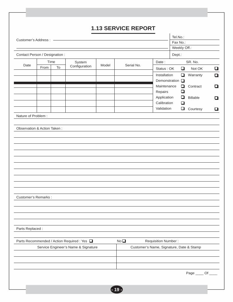
Customer’s Address :
1.13 SERVICE REPORT
Contact Person / Designation :
Tel.No.:
Fax No.:
Weekly Off.:
Dept.:
Date
Nature of Problem :
Observation & Action Taken :
Customer’s Remarks :
Parts Replaced :
Parts Recommended / Action Required : Yes
Service Engineer’s Name & Signature
Requisition Number :
Customer’s Name, Signature, Date & Stamp
Page ____ Of ____
No
Model Serial No.Date :
Status : OK
Installation
Demonstration
Maintenance
Repairs
Application
Calibration
Validation
Not OK
Warranty
Contract
Billable
Courtesy
SR. No.SystemConfiguration
Time
From To
- 19 -