operation manual gsm modem irz tg21 1. introduction 1.1. about this document the operation manual is...
TRANSCRIPT

Operation Manual
GSM modem iRZ TG21
2
Table of Contents
1. Introduction ............................................................................................................................. 4
1.1. About this Document ............................................................................................................................ 4
1.2. Service Information ............................................................................................................................... 4
1.3. Safety Precautions ............................................................................................................................... 4
2. Overview .................................................................................................................................. 5
2.1. Purpose ................................................................................................................................................ 5
2.2. Package Contents ................................................................................................................................ 5
2.3. Specifications........................................................................................................................................ 5
2.4. Device View .......................................................................................................................................... 7
2.5. Interfaces .............................................................................................................................................. 9
2.5.1. Terminal Strip Connector .............................................................................................................. 9
2.5.2. Power connector (12 V output) ................................................................................................... 11
2.6. The Modem Status Indication ............................................................................................................. 12
3. Connection and Configuration ............................................................................................. 13
3.1. Connection.......................................................................................................................................... 13
3.2. Control, Reset and Power Off ............................................................................................................. 13
3.3. Menu mode ......................................................................................................................................... 14
3.4. Programming mode ............................................................................................................................ 17
4. Emergencies .......................................................................................................................... 20
4.1. Emergency 1 (incorrect input power supply) ...................................................................................... 20
4.2. Alarm 2 (incorrect module power supply) ........................................................................................... 20
4.3. Emergency 3 (GSM module failed to run) .......................................................................................... 20
5. Support .................................................................................................................................. 21

3
List of Tables
Table 2.1 Terminal strip connector pin assignments ........................................................................................... 10
Table 2.2 Power connector pin assignments ....................................................................................................... 11
Table 2.3 Connection status indication (green LED) ........................................................................................... 12
Table 2.4 Fault condition indication (red LED) ..................................................................................................... 12
List of Figures
Fig. 2.1 Front panel ................................................................................................................................................ 7
Fig. 2.2 Back panel ................................................................................................................................................ 8
Fig. 2.3 Strip connector (a) ..................................................................................................................................... 9
Fig. 2.4 Power Connector .................................................................................................................................... 11
Fig. 3.1 Overview of the program ......................................................................................................................... 17
Fig. 3.2 Port opening ............................................................................................................................................ 18
Fig. 3.3 Loading update file. ................................................................................................................................. 18
Fig. 3.4 File uploaded message ........................................................................................................................... 18
Fig. 3.5 Writing into Flash-memory. ..................................................................................................................... 19
Fig. 3.6 Exiting program mode ............................................................................................................................. 19

4
1. Introduction
1.1. About this Document
The operation manual is intended for skilled PC users and provides the description and operating
procedure of the iRZ TG41 GSM modem.
1.2. Service Information
Document version Issue Date
1.4 01/02/2016
Written by: V. N. Golovin, P. V. Malikova Approved by: P. A. Kosolapov
1.3. Safety Precautions
Restrictions on the router use near other electronic devices:
Power off the modem in medical centres and keep it away from medical equipment (cardiac
pacemakers, hearing aids). Medical equipment may be susceptible to any form of radio interference. In
such areas the modem can transmit signals that could interfere with this equipment.
Power off the modem in an aircraft. Take measures against accidental activation;
Power off the modem near gas stations, enterprises of chemical industry, in areas where blasting
operations are in progress. The modem can interfere with operation of technical devices.
At close range the modem can interfere with television and radioreceiver operation.
To ensure safe operation, follow the recommendations:
Do not expose the modem to aggressive influences (high temperatures, corrosive chemicals, dust,
water, etc.).
Protect the modem from impacts, falls and excessive vibration.
Do not attempt to disassemble or modify the modem. Such actions will void the warranty.
Note: Use the device in compliance with the operating instructions. Damages caused by improper use and
storage of the device are not covered by the warranty.
Note! All wiring and electrical connection must be performed by a qualified electrician!

5
2. Overview
2.1. Purpose
The iRZ TG21 modem is a stand-alone GSM modem designed for transmission of data, text and fax
messages. It is well-designed for mobile Internet access, as well as for industrial applications: telemetry,
wireless data collection from sensors, remote surveillance and signalling.
The modem is fitted with watchdog timer that enables tracking its deadlock as well as restarting it. Also it is
possible to restart modem at set periods of time. The modem is controlled via standard AT commands as well
as some control commands of its own. It is fitted with LED lights to indicate connection status and possible
faults.
The modem's main intended use is remote polling via CSD channel. Thus, the respective settings are
integrated into the modem. For more details, see chapter 2.5.1.
2.2. Package Contents
The iRZ TG 21 GSM modem package includes:
iRZ TG21 modem;
Original package.
2.3. Specifications
General characteristics:
Frequency bands: GSM 900/1800 MHz
Output power:
2W (Class 4 for EGSM 900),
1W (Class 1 for GSM1800),
GPRS Class 8
TCP/IP stack, available via AT commands;
MS Class B;
CSD up to 14.4 kbps;
USSD;
SMS;
Fax group 3: Class 1;

6
Power Supply
Power supply voltage – 100 to 240 V
Input voltage frequency – 50/60 Hz
Current consumption – max 300 mA
The 6P6C modular plug and terminal connector output voltage – 12 V to 14,5 V
Maximal total current at 6P6C and connector does not exceed 100 mA
Physical Specifications
Dimensions – max 90х54х59 mm
Weight: max 115 grams;
Operating temperature: -20°C to +65°C
Storage temperature: -50°C to +85°C
Interfaces:
Power connector TJ6-6P6C for RJ12 – power output for external devices.
Terminal connector – connection of data communication cable (RS485), 220V power supply
SMA-F antenna connector – GSM antenna connection
TG21 GSM modem is fitted with BGS2-E8 module which can operate with SIM cards of any operator in the
following countries:
China
Hong Kong
Taiwan
Macao
Mongolia
Russia
Ukraine
Armenia
Azerbaijan
Belarus
Georgia
Kazakhstan
Kyrgyzstan
Moldavia
Tajikistan
Turkmenistan
Uzbekistan
Latvia
Lithuania
Estonia

7
1
2
3
4
5
Module configuration for specific country is carried out at the factory and connot be changed via AT
commands.
BGS2-W is an improved variation of the GSM module which can operate in every country of the world (see
notes for BGS2-W GSM module).
2.4. Device View
The TG21 modem is a compact-size device encased in a plastic housing. The device general view is given
in Fig. 2.1 and Fig. 2.2
Fig. 2.1 Front panel
The numbers in the figure illustrate:
1. LED indicators – failure (red on the right) and network (green on the left);
2. SMA-F antenna connector – GSM antenna connection;
3. SIM card tray;
4. Eject button for SIM card tray;
5. TJ6-6P6C power supply connector.

8
6
Fig. 2.2 Back panel
The numbers in the figure illustrate:
6. Strip connector, RS485 communication cable connection and power.

9
- + _
Sh + - + Sh B A NC N NC L1
1 2
3 4 5
9 8
2.5. Interfaces
2.5.1. Terminal Strip Connector
Terminal strip connector is used for connection to a control device, RS485 serial communications and
power connection. The modem is controlled via AT commands (see the command description on the module).
Factory settings: speed 9600 bit/s, data bit – 8, parity – no, stop bit – 1.
The view of the terminal strip connector is shown in Fig. 2.3 and Fig, 2.4:
Fig. 2.3 Strip connector (a)
7 6

10
4 3
7 9
6
- + Sh B A NC N NC L1
Fig. 2.4 Strip Connector (b)
Table 2.1 Terminal strip connector pin assignments
Strips Signal Function
1 - pin 12V (max 100 mA) strip “–”
2 + pin 12V (max 100 mA) strip “+”
3 Sh “Display” RS485
4 “B” “d-“ RS485;
inverted differential input
Interface's lines are protected by polyfuse and burst interference cancel circuit as well as surge voltage protector.
5 “A” “d+“ RS485;
noninverted differential input
6 NC Not used
7 N Power ~220V, 50Hz
8 NC Not used
9 L1 Power ~220V, 50Hz
*For example, it can be used for powering RS485 interface, heat calculators, electric meters etc.
Note: When receiving/transmitting data via interface note that the RS485 interface is half-duplex. When
echo is enabled, data sent to the modem is transmitted back, that might produce collision. It is required to disable echo (ate0 AT command) to eliminate this problem.
2 1
5
8

11
2.5.2. Power connector (12 V output)
TJ6-6P6C connector and the connector's pins №1 and №2 are used for powering external devices.
Fig. 2.4 Power Connector
Table 2.2 Power connector pin assignments
Pin Signal Function
1 + 12V pin 12V (max 100 mA) strip “+”
2 NC not used
3 NC not used
4 NC not used
5 NC not used
6 GND System Housing
Note! Total current at TJ6-6P6C and connector's pins №1 and №2 must not exceed 100mA.

12
2.6. The Modem Status Indication
The modem is provided with LED indication for displaying the connection state. This function is controlled
via AT command AT^SSYNC (AT^SSYNC=1 — on; AT^SSYNC=0 — off). By default, the value is
AT^SSYNC=1 (on)
Table 2.3 Connection status indication (green LED)
Status display mode Schematic LED signals representation
Operating mode
Off ○ The modem is switched off or at fault condition; power-saving mode; "ALARM" mode
600 ms on / 600 ms off ●●●●●●○○○○○○ The modem is not registered to the network
75 ms on / 3 s off ●○○○○○○○○○...○ The modem is registered on the network
75 ms on / 75 ms off
75 ms on / 3 s off
●○●○○○○○○○...○ GPRS connection is established
500 ms on / 50 ms off ●●●●●○ Transmitting data (GRPS)
250 ms on / 10 s off ●●●○○○○○○○...○ Modem is in hibernation mode
250 ms on / 250 ms off ●●●○○○ Programming mode, menu mode
Continuously unlit. ● Voice call, CSD
Table 2.4 Fault condition indication (red LED)
Status display mode Schematic LED signals representation
Fault description
Continuously lit ● Wrong input voltage
0.5 s on / 0.5 s off ●●○○ Wrong module power
0,25 s on / 0,25 s off / 0,25 s on / 1 s off
●○●○○○○ GSM module failed to start

13
3. Connection and Configuration
3.1. Connection
All installation operations are to be carried out by a qualified specialist familiar with the installation guide.
Before supplying power, install the SIM card into the modem. SIM card installation and removing is to be
carried out only when the device is powered off. To install SIM card, follow the steps:
remove a SIM card tray pressing the eject button (see Fig. 2.1.);
insert a SIM card into the SIM card tray;
insert the SIM card tray into the modem.
Do not apply much force when inserting a SIM card.
Connect a GSM antenna and a switching cable (RS485). Turn the modem's power supply on via power
connector or disruptive connector (see Fig. 2.2). After the modem has been powered, it will start. It will be
indicated with frequent flashing of green LED (see Table 2.3). If PIN code is switched off, registration within
network will occur automatically. As soon as the registration is complete the modem switches to an operation
mode, the indicator blinks less frequently.
The modem's main intended use is remote polling via CSD channel. Thus, the following settings are
integrated into the modem:
ats0=1 (automatic response);
at&c1 (determining DCD mode);
at&d0 (ignoring DTR);
at+cbst=71,0,1 (type of data transferring service);
ate0 (disabling echo).
Note: A GSM antenna, switching cables and a power supply unit are not included.
3.2. Control, Reset and Power Off
The modem is controlled using standard AT commands as well as a set of original commands (see GSM
module AT commands description). Additional information can be found on the websites www.radiofid.ru and
www.irz.net.
You can reboot the modem in the following ways:
Reboot after a set period of time (WD interval, switched off by default). Configured in the Menu mode;
by AT command “AT+CFUN=1,1”;
by temporary powering off.
You can turn off the modem in the following ways:
by powering off;
by AT command “AT^SMSO”.
14
If modem was turned off with AT command, alarm function can be used to switch it back on (ALARM
mode).
Switching to power saving mode is done with AT command “AT+CFUN”. ALARM mode control is carried
out with AT command “AT+CALA”. For more detailed information, see description of AT commands for GSM
module.
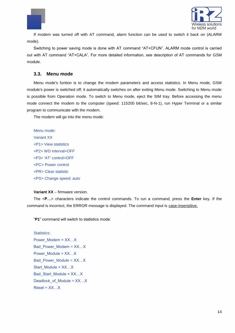
3.3. Menu mode
Menu mode's funtion is to change the modem parameters and access statistics. In Menu mode, GSM
module's power is switched off; it automatically switches on after exiting Menu mode. Switching to Menu mode
is possible from Operation mode. To switch to Menu mode, eject the SIM tray. Before accessing the menu
mode connect the modem to the computer (speed: 115200 bit/sec, 8-N-1), run Hyper Terminal or a similar
program to communicate with the modem.
The modem will go into the menu mode:
Menu mode:
Variant XX
<P1> View statistics
<P2> WD interval=OFF
<P3> 'AT' control=OFF
<PC> Power control
<PR> Clear statistic
<PS> Change speed: auto
Variant XX – firmware version.
The <P…> characters indicate the control commands. To run a command, press the Enter key. If the
command is incorrect, the ERROR message is displayed. The command input is case-insensitive.
“P1” command will switch to statistics mode:
Statistics:
Power_Modem = XX…X
Bad_Power_Modem = XX…X
Power_Module = XX…X
Bad_Power_Module = XX…X
Start_Module = XX…X
Bad_Start_Module = XX…X
Deadlock_of_Module = XX…X
Reset = XX…X

15
When using the modem, the following events are automatically saved.
Power_Modem – the number of the modem actuations;
Bad_Power_Modem – the number of power deviations of the modem;
Power_Module – the number of power supplies applied to the GSM module;
Bad_Power_Modem – the number of power deviations of the GSM module;
Start_Module – the number of successful starts of the GSM module;
Bad_Start_Module — the number of failed starts of the GSM module;
Deadlock_of_Module — the number of GSM module deadlocks;
Reset – the number of reboots.
After displaying statistics, the modem will switch to Main Menu
“P2” command will switch to WD mode:
WD interval, hour (0 - WD off, max - 255)
<Q> Quit
WD interval=
This sets the time interval for module restart. For changing this interval, enter number from 0 to 255 and
press "Enter" key. Interval is set in hours. To disable this function enter 0. Please note, that the modem will be
forced to restart after interval expiration. If entry is incorrect, "ERROR" message will be displayed and you will
be redirected to WD menu again. If entry is correct or after entering “Q” command, you will be redirected to
Main menu.
Command “P3” switches to AT submenu.
'AT' control, minutes (0 - off, max - 255)
<Q> Quit
control=
This submenu sets interval of checking module deadlock by managing microcontroller. For changing this
interval, enter number from 0 to 255 and press "Enter". Interval is set in minutes. To disable this function enter
0. If entry is incorrect, "ERROR" message will be displayed and you will be redirected to AT submenu again. If
entry is correct or after entering <Q> command, you will be redirected to Main menu.
Entering the “PC” command allows to review the input voltage and the voltage of the module (measurement
precision 5%):
P0WER Uin=12.0 Umd=3.9
After displaying data, the modem will switch to Main Menu
“PR” command will switch to statistics reset menu:
Clear statistic?
<YES> YES

16
<Q> Quit
Reset the accumulated statistics by <YES> command. If entry is incorrect, "ERROR" message will be
displayed and you will be redirected to WD menu again. If entry is correct or after entering <Q> command, you
will be redirected to Main menu.
“PS” command will enter menu of determining data transmission speed. Modem is always set to receive
data. A switch to transition occurs when data to be transmitted appears. Setting a fixed speed of data
transmission eliminates errors in calculating the interval of transmission switch. This allows minimizing pauses
between transmission and reception of data. More importantly, it eliminates the possibility of losing the data at
the beginning of the transmission. By default, the modem is set to automatically detect speed of data
transmission.
Menu speed:
<0> auto
<1> 115200
<2> 57600
<3> 38400
<4> 28800
<5> 19200
<6> 14400
<7> 9600
<8> 4800
<9> 2400
<10> 1200
<11> 600
<12> 300
<Q> Quit
For changing the speed, enter number from 1 to 12 and press "Enter" key. To disable this function enter 0.
If entry is incorrect, "ERROR" message will be displayed and you will be redirected to WD menu again. If entry
is correct or after entering <Q> command, you will be redirected to Main menu.
Entering “M” command switches to back Main menu.
The exit from Menu mode occurs after inserting SIM tray

17
3.4. Programming mode
Program “mprog” is used to change or update software of the managing microcontroller of the modem via
RS485 interface. Fig. 3.1 shows interface and main features of the program.
1 – language change, 2 – working with ports, 3 – working with flash memory, 4 – working with EEPROM
memory,
5 – START button, 6 – view window.
Fig. 3.1 Overview of the program
To update firmware, it is required to take following steps. If within 10 seconds the update has not started,
the modem will switch to Menu mode.
1. Start the program;
Close all programs, which may use the port you will use to connect to the modem.
2. Click the button in the PORT frame;
3. Choose the number of port you will use to connect to the modem;
4. Connect the modem (without the SIM tray) to the PC and then switch modem's power on.
The modem will switch to programming mode. The green indicator will be flashing. 250 ms on / 250 ms off

18
5. Click the button in the PORT frame;
The device's model name will be displayed. For example, in Fig. 3.2 it is MC52i-485 (or BGS2-485).
Fig. 3.2 Port opening
Then select the new firmware file to be downloaded.
6. Click the button in the FLASH frame and select firmware file (.hex extension) in
"Open file" dialog.
For example, in Fig. 3.3 it is “rs485_bgs2_v4.0.hex”.
Fig. 3.3 Loading update file.
If the file has uploaded successfully, the program window will show message “Uploaded file”: For example,
as shown in the figure below.
Fig. 3.4 File uploaded message
7. Click the button in the FLASH frame;
After this, data will be written in Flash-memory. The following message will be displayed:

19
Fig. 3.5 Writing into Flash-memory.
8. Next, click the button at the bottom of the window;
Next, modem will exit the Programming mode and the port will be closed.
Fig. 3.6 Exiting program mode
9. Close the program
10. Insert SIM tray into the modem.
Firmware update is completed. The modem will now enter Operation mode.

20
4. Emergencies
To facilitate the use of the modem, tracking and display of emergencies are provided.
4.1. Emergency 1 (incorrect input power supply)
Emergency 1 occurs when the input power supply deviates from the permissible value. The modem stops
operating and switches off GSM module power supply. Red LED signal is continuously lit to indicate
emergency. The recovery is possible only when the input power supply is re-established.
4.2. Alarm 2 (incorrect module power supply)
Emergency 2 occurs when GSM module's' power supply deviates from the permissible value. The modem
stops operating and switches off GSM module power supply. A red LED signals that the emergency has
occurred (0.5s on / 0.5s off). The recovery is possible only if the module power supply is re-established within
10 seconds after the emergency occurred. If within 10 seconds the module power supply remains incorrect
(with a correct input power supply), the modem goes into the waiting mode meaning that the modem’s power
supply is turned off, the emergency indication is preserved. The waiting mode can be terminated only after the
power is completely disconnected.
In case of repeated emergency, the modem should be serviced.
4.3. Emergency 3 (GSM module failed to run)
Emergency 3 occurs if the GSM module does not turn on or is absent. A red LED signal (0.25s on / 0.25s
off / 0.25s on / 1s off) turns on after the modem precisely detects the emergency situation (~15 sec). The
recovery is possible only after a successful launch of the GSM module. After 10 unsuccessful attempts to
launch the module, the modem goes into the waiting mode. The modem’s power supply is turned off, the
emergency indication is preserved. The waiting mode can be terminated only after the power is completely
disconnected.
In case of repeated emergency, the modem should be serviced.

21
5. Support
To get updated documents and software updates, please use the following contacts:
St. Petersburg
The company’s website: www.radiofid.ru
Phone number in St. Petersburg: +7 (812) 318 18 19
E-mail: [email protected]
Moscow
The company’s website: www.digitalangel.ru
Phone number in Moscow: +7 (495) 974 74 22
E-mail: [email protected]
Our specialists are always ready to answer your questions, assist in installation or configuration, and solve
problems regarding the equipment operation.