operation manual - kent industrial usa
TRANSCRIPT

- 1 -
LARGE HEAVY DUTY LATHE
Model:MD-47, 55, 63, 70
Operation Manual
Prop
erty o
f Ken
t Indu
strial
USA
Please
Do N
ot Rep
roduc
e

- 2 -
INDEX CHAPTER 1 SPECIFICATIONS .............................................................................................................. 4 CHAPTER 2 INSTALLATION ................................................................................................................ 11
2.1 UNPACKING .................................................................................................................................... 11 2.2 MOVING & LIFTING ...................................................................................................................... 11 2.3 FOUNDATION WORK .................................................................................................................... 11 2.4 CLEAN UP ........................................................................................................................................ 11 2.5FOUNDATION .................................................................................................................................. 12 2.6 LEVEL OF LATHE .......................................................................................................................... 13
CHAPTER 3 POWER SECURITY CONTROL .................................................................................... 14 3.1 ELECTRICAL BOX ......................................................................................................................... 14 3.2 ELECTRICAL SAFETY FEATURES .............................................................................................. 14 3.3 CAUTION ......................................................................................................................................... 14
CHAPTER 4 PREPARATION FOR OPERATION .............................................................................. 22 4.1 SPINDLE ROTATION, STOP AND RESTART ............................................................................. 22 4.2 OPERATION OF JOGGING SWITCH PUSH BUTTON ............................................................... 23 4.3 CHANGE GEAR SYSTEM .............................................................................................................. 23
4.3.1 RAPID TRAVEL: .................................................................................................................. 26 4.4 MANUAL, FEED .............................................................................................................................. 28 4.5 AUTOMATIC FEED ........................................................................................................................ 28 4.6 SWIVEL SLIDE ................................................................................................................................ 28 4.7 TAILSTOCK ..................................................................................................................................... 28
CHAPTER 5 THREADING ...................................................................................................................... 29 5.1 LEADSCREW OPERATION ........................................................................................................... 29 5.2 THREAD SYSTEM .......................................................................................................................... 29 5.3 THREADING INDICATOR (table3 P.22) ....................................................................................... 29 5.4 Operation steps of Auto Rapid Threading Device (Opt.) .................................................................. 30
CHAPTER 6 MAINTENANCE ................................................................................................................ 34 6.1 LUBRICATIONS .............................................................................................................................. 34
6.1.1 Lubrication in headstock & norton feed gear box & apron box. ............................................ 34 6.1.2 Lubrication in change gears .................................................................................................... 34 6.1.3 Lubrication in carriage and apron ........................................................................................... 34 6.1.4 Lubrication in compound rest, lead screw and lead screw bracket ........................................ 34 6.1.5 Coolant for cutting .................................................................................................................. 34 6.1.6 Lubricant Table ....................................................................................................................... 34
6.2 Lubrication System ............................................................................................................................ 35 Part List .......................................................................................................................................................... 38
BED ......................................................................................................................................................... 39 HEADSTOCK ......................................................................................................................................... 41 GEAR BOX ............................................................................................................................................. 46
Propert
y of K
ent In
dustr
ial U
SA
Please
Do N
ot Rep
roduc
e

- 3 -
APRON-LEFT HANDWHEEL .............................................................................................................. 51 APRON-RIGHT HANDWHEEL ............................................................................................................ 53
THERADING INDICATOR OF HANDWHELL APRON ............................................................ 55 TAILSTOCK ........................................................................................................................................... 57 COMPOUND SLIDE .............................................................................................................................. 63 COMPOUND SLIDE WITH TAPER ATTACHMENT (option) ........................................................... 66 TAPER ATTACHMENT (option) .......................................................................................................... 70 HYDRAULIC COPY DEVICE (Option) ................................................................................................ 72 6-WAY RAPID TRAVERSE (Option) ................................................................................................... 74 FOLLOW REST (Option) ....................................................................................................................... 76 HYDRAULIC REAR SUPPORTING STAND (Option) ....................................................................... 78
Propert
y of K
ent In
dustr
ial U
SA
Please
Do N
ot Rep
roduc
e

- 4 -
CHAPTER 1 SPECIFICATIONS
MODEL
ITEM
47
SERIES
55
SERIES
63
SERIES
70
SERIES Center high 600 mm 700 mm 800 mm 900 mm Swing over bed 1200 mm(47”) 1400 mm(55”) 1600 mm(63”) 1800 mm(70”) Swing over cross slide 830 mm 1030 mm 1230 mm 1430 mm Swing over gap 1750 mm 1950 mm 2150 mm 2350 mm Width of gap 600 mm Width of bed 800 mm
Distance between centers 2000(80”),3000(120”),4000(160”),5000(200”), 6000(240”),7000(280”),8000(320”),9000(360”)
Spindle bore Ø230mm Ø260mm Ø310mm Ø360mm Ø535mm Spindle nose A2-15 A2-15 A2-20 A2-20 A2-28 Number of Spindle speeds 6-400 6-400 5-300 5-300 3-230 Tailstock spindle Ø200 mm (Ø290mm Rotary Quill Optional) Taper of center MT#7 Quill travel 300mm Cross feeds 0.065-0.96(48Kinds) Cross travel 780mm Compound rest travel 350mm Tool size 50 x 50 Longitudinal feeds 0.13-1.92 (48Kinds) Lead screw diameter Ø50mm x 2TPI Threading range, metric 2-30mm/Pitch (48Kinds) Threading range, inch 1-15 TPI (48Kinds) Module pitch threads 1-15M (32Kinds) DP. Pitch threads 2-30P (48Kinds) Main spindle motor 30HP (40HP,50HP Optional) Rapid motor 1/2 HP Coolant pump 1/4 HP Oil pump 12W
* This book consists of all possible options. Your machine might not have some of them.
Propert
y of K
ent In
dustr
ial U
SA
Please
Do N
ot Rep
roduc
e

- 5 -
A
C
B
.
Propert
y of K
ent In
dustr
ial U
SA
Please
Do N
ot Rep
roduc
e

- 6 -
A
C
B
Propert
y of K
ent In
dustr
ial U
SA
Please
Do N
ot Rep
roduc
e

- 7 -
A
C
B
Propert
y of K
ent In
dustr
ial U
SA
Please
Do N
ot Rep
roduc
e

- 8 -
B
C
A
Propert
y of K
ent In
dustr
ial U
SA
Please
Do N
ot Rep
roduc
e

- 9 -
Propert
y of K
ent In
dustr
ial U
SA
Please
Do N
ot Rep
roduc
e
- 10 -
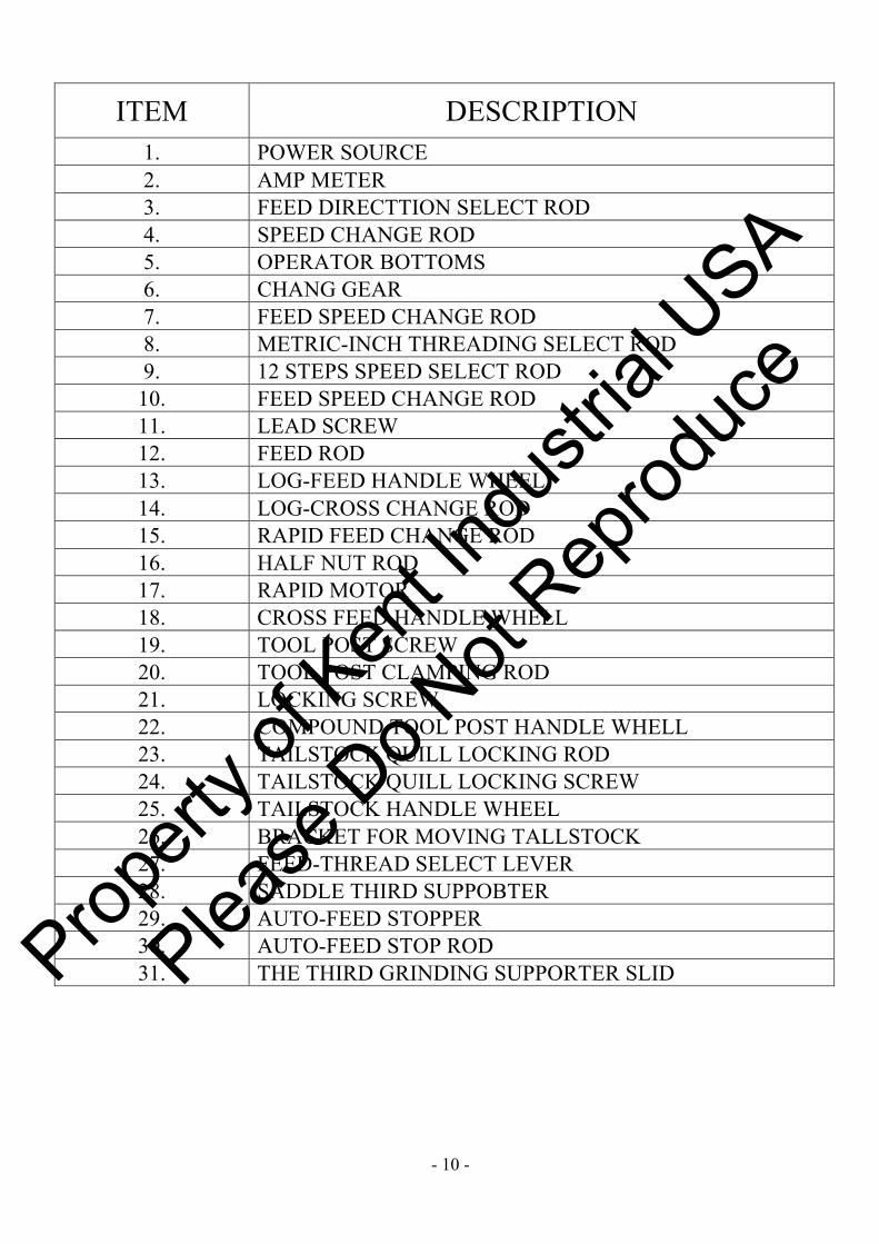
ITEM DESCRIPTION 1. POWER SOURCE 2. AMP METER 3. FEED DIRECTTION SELECT ROD 4. SPEED CHANGE ROD 5. OPERATOR BOTTOMS 6. CHANG GEAR 7. FEED SPEED CHANGE ROD 8. METRIC-INCH THREADING SELECT ROD 9. 12 STEPS SPEED SELECT ROD
10. FEED SPEED CHANGE ROD 11. LEAD SCREW 12. FEED ROD 13. LOG-FEED HANDLE WHEEL 14. LOG-CROSS CHANGE ROD 15. RAPID FEED CHANGE ROD 16. HALF NUT ROD 17. RAPID MOTOR 18. CROSS FEED HANDLE WHELL 19. TOOL POST SCREW 20. TOOL POST CLAMPING ROD 21. LOCKING SCREW 22. COMPOUND TOOL POST HANDLE WHELL 23. TAILSTOCK QUILL LOCKING ROD 24. TAILSTOCK QUILL LOCKING SCREW 25. TAILSTOCK HANDLE WHEEL 26. BRACKET FOR MOVING TALLSTOCK 27. FEED-THREAD SELECT LEVER 28. SADDLE THIRD SUPPOBTER 29. AUTO-FEED STOPPER 30. AUTO-FEED STOP ROD 31. THE THIRD GRINDING SUPPORTER SLID
Propert
y of K
ent In
dustr
ial U
SA
Please
Do N
ot Rep
roduc
e

- 11 -
CHAPTER 2 INSTALLATION
2.1 UNPACKING Inspect the machine. If there is any shortage or damage, contact your local dealer immediately.
2.2 MOVING & LIFTING Move &lift the machine by using a 1 1/2” diameter and 32” long iron bar. Go through the hole of left leg. And lift unpacking machine with a wire rope, which have enough capacity against gross weight of chine, as the method shown in the figure, raising and lowering the machine should be careful. Do not to hump the machine against the floor. Before moving please check the following items: (1) Clamp Tailstock (2) Lock saddle lock (3) Engage half nut with lead screw
2.3 FOUNDATION WORK At present, the super-hard alloy tools are used for high speed lathe. The cutting speed and the spindle speed are much higher then before. An incomplete foundation is apt to produce vibration. Since super-hard tool is Easily influenced by the vibration, the foundation work should be done as the figure shown. Enough space and boundary are necessary. The machine should be installed at least 2 ft. from the wall and other machines.
2.4 CLEAN UP Anticorrosive is applied on the machine. For cleaning up the bed, slides, and lead screw, etc, use dissoluble solvent to take off the anticorrosive. Do not use lacquer thinner or gasoline. Apply machine oil to all the necessary positions. Check all the handles and levers to see if it is functioning properly. Then set on neutral position
.
Propert
y of K
ent In
dustr
ial U
SA
Please
Do N
ot Rep
roduc
e

- 12 -
2.5FOUNDATION
Propert
y of K
ent In
dustr
ial U
SA
Please
Do N
ot Rep
roduc
e

- 13 -
2.6 LEVEL OF LATHE Anchor bolts and installation blocks must be fixed steadily to the cement. For alignment of the machine, place spirit level which has sensitivity better than 0.02mm/1000mm, on guide ways of bed, adjust the level of the bed-way from left to right, then adjust the level of saddle, both front and rear, make sure the sensitivity is within 0.04mm/1000mm. After the adjustment of level, fast the nuts if flatness is deviated by fastening Nuts, adjust it again until no deviation is found.
Propert
y of K
ent In
dustr
ial U
SA
Please
Do N
ot Rep
roduc
e

- 14 -
CHAPTER 3 POWER SECURITY CONTROL 3.1 ELECTRICAL BOX
3.2 ELECTRICAL SAFETY FEATURES
(1)The control panel of this machine is equipped with magnetic contactor and overload thermal realy. (2)Forward/reverse lever and limited microswitch are connected. (3)Pedal brake device is connected to limited microswitch. (4)There is jogging switch push botton in top of headstock.
3.3 CAUTION After wiring, check the spindle rotating direction. Turn on the power source switch and push the jogging switch button. If it rotates counterclockwise, it is the correct wiring. If not, replace two of the three wires (R.S.T). then check the rotation again. The overload thermal relay is connected to the magnetic contactor to protect from motor overload. If the spindle speed drops to zero during normal operation, but the pilot light is still on, it indicates that the overload thermal relay and restart the machine.
Propert
y of K
ent In
dustr
ial U
SA
Please
Do N
ot Rep
roduc
e

- 15 -
POWER SOURCE
L abe l :
Cabl e Si z e:1. 25mm* 4c
Wi r i ng:
( 1) Mal e pl ugs i n c ont r ol box
( 2) Cabl e wi t h 1. 25- 3Y pl ugs i n e l ec t r i c c abi ne t
( 3) Cabl e wi t h f emal e pl ugs i n c ont r ol box
( 4) L engt h 3. 3M
1, 2, 70, 71
Propert
y of K
ent In
dustr
ial U
SA
Please
Do N
ot Rep
roduc
e

- 16 -
T BF - 251Y
T BM- 251R
T BF - 251G
PB4A
PB4
PBR1
PUMP
T BF - 251G
T SS- 251B
PBF1
CS2
FWD
REV
FWD J OG
PB2
EMERGENCY STOP
REV J OG
POWER STOP
PB10
L abe l :
Cabl e Si z e:0. 75mm* 16c
Wi r i ng:( 1) Mal e pl ugs i n c ont r ol box
( 2) Cabl e wi t h 1. 25- 3Y pl ugs i n e l ec t r i c c abi ne t
( 3) Cabl e wi t h f emal e pl ugs i n c ont r ol box
( 4) L engt h 3. 7M
Propert
y of K
ent In
dustr
ial U
SA
Please
Do N
ot Rep
roduc
e

- 17 -
RL PB5 PB3 PB6
PBF2 PBR2 PB7
T PNR- 251 R T BF - 251 Y T BM- 251R T BF - 251Y
T BF - 251YT BF - 251GT BF - 251G
PB11
T BF - 251 R
Propert
y of K
ent In
dustr
ial U
SA
Please
Do N
ot Rep
roduc
e

- 18 -
RL PB5 PB3 PB6
PBF2 PBR2 PB7
T PNR- 251 R T BF - 251 Y T BM- 251R T BF - 251Y
T BF - 251YT BF - 251GT BF - 251G
Propert
y of K
ent In
dustr
ial U
SA
Please
Do N
ot Rep
roduc
e

- 19 -
RL PB5 PB3 PB6
PBF2 PBR2 PB7
T PNR- 251 R T BF - 251 Y T BM- 251R T BF - 251Y
T BF - 251YT BF - 251GT BF - 251G
Propert
y of K
ent In
dustr
ial U
SA
Please
Do N
ot Rep
roduc
e

- 20 -
Propert
y of K
ent In
dustr
ial U
SA
Please
Do N
ot Rep
roduc
e

- 21 -
Propert
y of K
ent In
dustr
ial U
SA
Please
Do N
ot Rep
roduc
e

- 22 -
CHAPTER 4 PREPARATION FOR OPERATION
4.1 SPINDLE ROTATION, STOP AND RESTART
(1) Turn on power source switch ○1
(2) Set lever ○3 at neutral position (middle Position).
(3) Set the spindle speed lever ○4 to the needed speed. Then set ○5○6 High/Low speed control lever to either
high or low position speed chart shown in Table-1.
(4) Push Forward/Reverse control switch○32 to get to forward or reverse revolution.
(5) To stop the spindle rotation by pushing brake: button○37
(6) To restart the spindle rotation, use the same Forward/Reverse control switch as before you stop. CAUTIONS!! (1) Stop spindle rotation before changing spindle speed. Otherwise, the headstock gear will be damaged.
(2) If it is hard to set the lever on position when change the speed, push the jogging switch ○36 then set the
change gear lever again.
○1 ○4 ○5 ○6 ○32
○36
○3
○37
Propert
y of K
ent In
dustr
ial U
SA
Please
Do N
ot Rep
roduc
e

- 23 -
Table-1
4.2 OPERATION OF JOGGING SWITCH PUSH BUTTON
There is a push button ○36 in top of headstock (see Fig. 7). Push it slightly. The spindle will run positively
and stop automatically. This is for changing speed easier and adjusting the center for raw material when a 4-jaw chuck is used.
4.3 CHANGE GEAR SYSTEM The change gear system is located at the left side of the headstock. Please refer to thread cutting chart, table 2, be sure that the gears are aligned after you have changed them. Caution: Don’t attempt to change gears While spindle is rotating.
○36
Propert
y of K
ent In
dustr
ial U
SA
Please
Do N
ot Rep
roduc
e

- 24 -
LE
VE
RS
EDD CC
F
W I
NC
H T
HR
EA
DW
DP
TH
RE
AD
EC D
FLE
VE
RS C D
M M
ET
RIC
TH
RE
AD
LE
VE
RS
EF
DCDC
M M
OD
UL
E T
HR
EA
D
EC D
FLE
VE
RS C D
TA
BL
E-2
TA
BL
E-2
,TH
RE
AD
CU
TT
ING
CH
AR
T
Propert
y of K
ent In
dustr
ial U
SA
Please
Do N
ot Rep
roduc
e

- 25 -
(INCH)LEVERS
E
F
DC
DC
TABLE-2-1
FEED SPEED
ED
F
C
DC
LEVERSFEED SPEED
FEED SPEED
(METRIC)
Propert
y of K
ent In
dustr
ial U
SA
Please
Do N
ot Rep
roduc
e

- 26 -
4.3.1 RAPID TRAVEL: Please must confirm below two points before operating rapid travel. POINTS:
1. SELECT X OR Z AXIS RAPID TRAVEL: Pull up the lever ○14 to get longitudinal (Z) rapid travel,
pull down lever to get cross (X) rapid travel.
2. SELECT DIRECTION: Select switch ○34 or ○35.
3. If you don’t continuous to push ○34 or ○35 then, the rapid travel will be stopped.
○14 ○34 ○35
○33
○32
○16
○15
Propert
y of K
ent In
dustr
ial U
SA
Please
Do N
ot Rep
roduc
e

- 27 -
Threading Indicator: The threading indicator is installed on the side of apron. A. When the lathe with inch lead screw, the threading indicator is set 8 teeth gear, then it can suit various
proper points to threading cutting. As chart –5–1 B. When the lathe with metric lead screw, the threading indicator is set 12 teeth gear, but it need more
kinds of worm gear to suit various proper points to threading cutting As table–3
Threading indication table:
chart –5–1
chart –3 table–3
Change Steps: 1. According Table 6-1 to select out the indicate gear. 2. Turn the hand wheel○K until sensor○J catch the dog○I , the air cylinder○D will close the half nut
automatically. 3. Take apart the locking nut to change the indicate gear. Change Steps of Cutting Metric / Inch Threading: A. When the lead screw is metric: 1. Cut metric thread, must change indicate gear (The lever○L of half nut can open) cycle threading. 2. Cut inch thread, The lever○L of half nut must close, use positive and negative turning of main spindle
to back and forth threading. B. When the lead screw is inch: 1. Cut inch thread, must change indicate gear, (The lever○L of half nut can open) cycle threading. 2. Cut metric thread, The lever○L of half nut must close, use positive and negative turning of main spindle to back and forth threading.
PH T POINT PH T POINT 2.5
10 2
3.25
13 1 5 6.5
10 13 20 26
2.75
11 1
3.5
14 2 5.5 7 11 14 22 28 2.0
12 4
2.25
12 4 3.0 4.5 4.0 9.0 6.0 18 8.0
12.0
12 2 16.0 32.0
1 POINT 2 POINT 4 POINT 8 POINT
Sensor
Dog
Threading Indicator
Indicate Gear
Lock NutLead Screw
Propert
y of K
ent In
dustr
ial U
SA
Please
Do N
ot Rep
roduc
e

- 28 -
4.4 MANUAL, FEED
Carriage moves longitudinally by turning Hand wheel ○13 (Be sure to let lever ○15 ○18 at up position and pull levers ○16 up) Cross feed operated by handle wheel ○18 ○32 ○14 ○33
4.5 AUTOMATIC FEED ○16 ○13 Automatic feed is operated as billows ○15 (1) Choose feed direction by lever ○3 (2) Set change gears and shift levers ○8 & ○9 & ○10 to desired feed value. (3) Pull lever ○16 up. (4) Feed selector ○14 to select either longitudinal feed or cross feed. (5) Push switch ○32 to select direction of spindle rotation. (6) Automatic feed starts when ○15 lever is operated and stop when it is pulled up to neutral position.
4.6 SWIVEL SLIDE Loosen four cap screws before swiveling it.
4.7 TAILSTOCK Tailstock spindle moves out by turning hand wheel ○25 either the arbor of drill Chuck or tailstock spindle center comes out by excess returning of tailstock spindle. Tailstock spindle. Tailstock spindle is clamped by pushing lever ○23 counter direction. The tailstock clamped by 4 screws ○24.
Propert
y of K
ent In
dustr
ial U
SA
Please
Do N
ot Rep
roduc
e

- 29 -
CHAPTER 5 THREADING
5.1 LEADSCREW OPERATION Shift the lever ○3 to the right or left, the leadscrew run forward or reverse rotation respectively.
5.2 THREAD SYSTEM The thread cutting is operated as follow : (1) The change gears are aligned according to PAGE 10. (2) Lever Position: Please refer thread Cutting chart table 2. (3) Shift lever ○32 to select direction of spindle rotation. (4) Push lever ○16 down (half nut engaged) to start threading.
5.3 THREADING INDICATOR (table3 P.22) The threading indicator installed on the apron side has eight graduations. For cutting inch thread, the thread cutting indicator is prepared for correct position of half nut engaging conveniently and quickly. As to metric thread cutting, half nut should be engaged with lead screw completely (When lead screw is inch).Let tool post back up to starting position by reversing spindle rotation, then feed again. ○3 ○32 ○32 ○16
Propert
y of K
ent In
dustr
ial U
SA
Please
Do N
ot Rep
roduc
e

- 30 -
5.4 Operation steps of Auto Rapid Threading Device (Opt.)
Pic.1
Item Name 1 Spindle forward 2 Spindle jog 3 Spindle reverse 4 Spindle brake 5 4-way rapid traverse 6 ID/OD select 7 Auto threading stop 8 Auto threading start 9 Thread system select
○1
○9
○3
○5
○7
○2 ○4
○6 ○8
Primary / Secondary
Propert
y of K
ent In
dustr
ial U
SA
Please
Do N
ot Rep
roduc
e

- 31 -
Steps of auto threading
Pic.2
Pic.3
Pic.4
Pic.5
○A
○B
○C
○D
○E
○F ○G
○E
○F
○H
○H
○I
○ J ○ L
○ K
Propert
y of K
ent In
dustr
ial U
SA
Please
Do N
ot Rep
roduc
e

- 32 -
Sensor
Dog
Threading Indicator
Indicate Gear
Lock NutLead Screw Diag.1
* Primary threading system: (If the customer chooses inch / metric lead screw, the primary thread will be inch / metric thread; the other should be secondary thread.) 1. Move the carriage close to the beginning of the threading cycle. Lock the nuts of the hydraulic cylinder
bracket ○A (Move the carriage backward by Z-axis hand wheel to minimize the stroke of the piston rod of the hydraulic cylinder ○H ). Lock the taper attachment draw bar base ○B (if the taper attachment is installed). Adjust the taper on the taper attachment for turning. Please be aware of the travel limitation.
2. Before starting auto threading, please turn lever ○C to neutral position (shown in Pic.3); otherwise, the carriage behaves in feeding mode but not threading mode.
3. Fixed plate ○ J (shown in Pic.5) is used to fix the base of the toolpost ○K on the slide-way of the carriage ○L . It would be used to get better accuracy if the lathe is operated in feeding mode. Otherwise, in auto threading mode, please take off the screw to separate ○K from ○L .
4. Turn the switch ○9 left to select the primary threading system. 5. Make sure carefully that the spindle has stopped. Then, select ID or OD threading by Switch ○6 , and
then press Button ○8 to locate toolpost in a feeding position. Set the tooling depth by X-axis hand-wheel. After setting the x-axis, press Button ○7 , and hydraulic device ○D will pull the toolpost back to leave the threading position. (Be careful. If the spindle is rotating, the carriage will move on Z-axis when you press Button ○8 .)
6. Decide the end of the thread; you can locate the eccentric ring ○E (shown in Pic.4) on the stop rod to set the end of the travel on Z-axis. (If the micro switch ○F touches the eccentric ring, the threading travel ends.)
7. Make sure the carriage is in the beginning of the thread travel. Then, select the speed of the spindle and confirm the type of the thread by turning the levers on the headstock.
8. If you have already checked Item 1 to Item 7, press button ○1 to let the spindle rotate forward (so does the lead screw), and press button ○8 to start the auto threading cycle.
9. Cycle-threading: A. The hydraulic device ○D moves the toolpost to threading position, the pneumatic cylinder ○G pulls
the lever and it makes the half nuts closed; cycle starts. B. When the micro switch ○F touches the eccentric ring ○E , the threading travel ends. The hydraulic
device ○D lets the toolpost leave the threading position, the pneumatic cylinder ○G turns back the lever, and then half nuts open. After that, the hydraulic cylinder ○H will pull the whole carriage back to the beginning of the travel.
C. The Thread cutting indicator ○I indicates the thread pitch. The dog rotates along with the lead screw, and when the dog meets the sensor (shown in Diag.1), threading cycle (Step A to C) will go again. Before the next cycle starts, the operator could adjust the tooling depth by the X-axis hand wheel. (It means the pitch of the lead screw and the thread on the workpiece matches that the dog meets the sensor.)
Propert
y of K
ent In
dustr
ial U
SA
Please
Do N
ot Rep
roduc
e

- 33 -
10. Repeat the cycle several times to machine the thread. When the sufficient cycles have been done, press button ○7 to stop the auto threading function.
* Secondary threading system: 1. Move the carriage close to the beginning of the threading cycle. Unlock the nuts of the hydraulic cylinder
bracket ○A (shown in Pic.2) but lock the taper attachment draw bar base ○B (if the taper attachment is installed). Adjust the taper on the taper attachment for turning. Be aware of the travel limitation.
2. Before starting auto threading, please turn lever ○C to neutral position (shown in Pic.3); otherwise, the carriage behaves in feeding mode but not threading mode.
3. Fixed plate ○ J (shown in Pic.5) is used to fix the base of the toolpost ○K on the slide-way of the carriage ○L . It would be used to get better accuracy if the lathe is operated in feeding mode. Otherwise, in auto threading mode, please take off the screw to separate ○K from ○L .
4. Turn the switch ○9 right to select the secondary threading system. 5. Make sure carefully that the spindle has stopped. Then, select ID or OD threading by Switch ○6 , and
press Button ○8 to locate toolpost in a feeding position. Then set the tooling depth by X-axis hand wheel. After setting up the X-axis, press Button ○7 , and hydraulic device ○D will pull the toolpost back to leave the threading position. (Be careful. If the spindle is rotating, the carriage will move on Z-axis when you press Button ○8 .)
6. Decide the end of the thread; you can locate the eccentric ring ○E (shown in Pic.4) on the stop rod to set the end of the travel on Z-axis. (If the micro switch ○F touches the eccentric ring, the threading travel ends.)
7. Make sure the carriage is in the beginning of the thread travel. Then, select the speed of the spindle and confirm the type of the thread by turning the levers on the headstock.
8. Cycle-threading (please check Item 1 to Item 7): A. Press button ○8 to start the secondary threading system. Half nuts will be closed at the beginning. B. Press button ○1 to let the spindle rotate forward (so does the lead screw), and the carriage moves
forward. C. The hydraulic device ○D moves the toolpost to threading position. D. When the micro switch ○F touches the eccentric ring ○E , the threading travel ends. The spindle
stops, and the lead screw does, too. Then the hydraulic device ○D lets the toolpost leave the threading position. (Please notice that half nuts are still closed, and the hydraulic cylinder ○H won’t work at this system.)
E. Press button ○3 to rotate the spindle and lead screw reversely. When the carriage go back to the beginning, press button ○4 to stop spindle rotating and stop the carriage moving. Before the next cycle starts, the operator could adjust the tooling depth by the X-axis hand wheel.
9. Repeat the step A to E several times to get the thread. * DOG Adjustment of Threading Indicator: When we test running in our company, we set spindle speed from 45rpm to 65 rpm, and range of thread pitch about 5 TPI. When spindle drives fast, half nut engagement doesn’t speed up as lead screw’s speed. .Half nut will fail to match on lead screw teeth, making false on thread pitch or violent dash condition of air cylinder. Then, spindle should stop moving. Pushing on switch ○Q, rotating big hand wheel of Apron to make DOG and SENSOR match; air cylinder makes open-close nut match. Then loose the indicator, and draw DOG anti-clock about half range. Following these, when the range of speed is over larger, it needs to adjust the DOG, and the auto-threading will drive smoothly.
Propert
y of K
ent In
dustr
ial U
SA
Please
Do N
ot Rep
roduc
e
- 34 -
CHAPTER 6 MAINTENANCE
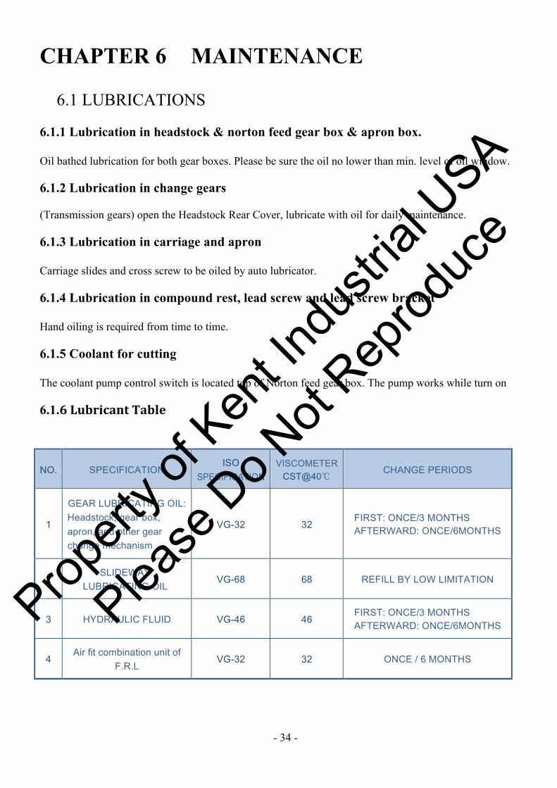
6.1 LUBRICATIONS 6.1.1 Lubrication in headstock & norton feed gear box & apron box. Oil bathed lubrication for both gear boxes. Please be sure the oil no lower than min. level of oil window. 6.1.2 Lubrication in change gears (Transmission gears) open the Headstock Rear Cover, lubricate with oil for daily maintenance. 6.1.3 Lubrication in carriage and apron Carriage slides and cross screw to be oiled by auto lubricator. 6.1.4 Lubrication in compound rest, lead screw and lead screw bracket Hand oiling is required from time to time. 6.1.5 Coolant for cutting The coolant pump control switch is located top of Norton feed gear box. The pump works while turn on 6.1.6 Lubricant Table
NO. SPECIFICATION ISO
SPECIFICATION VISCOMETER
CST@40℃ CHANGE PERIODS
1
GEAR LUBRICATING OIL: Headstock, gear box, apron, and other gear change mechanism
VG-32 32 FIRST: ONCE/3 MONTHS AFTERWARD: ONCE/6MONTHS
2 SLIDEWAY
LUBRICATING OIL VG-68 68 REFILL BY LOW LIMITATION
3 HYDRAULIC FLUID VG-46 46 FIRST: ONCE/3 MONTHS AFTERWARD: ONCE/6MONTHS
4 Air fit combination unit of
F.R.L VG-32 32 ONCE / 6 MONTHS
Propert
y of K
ent In
dustr
ial U
SA
Please
Do N
ot Rep
roduc
e

- 35 -
6.2 Lubrication System
OIL
WIN
DO
W
OIL
CIR
CU
LA
TIO
N I
ND
ICA
TO
R
OIL
PL
UG
GR
EA
SE
LU
BR
ICA
TIO
N
OIL
WIN
DO
W
OIL
OU
TL
ET
OIL
IN
LE
TO
IL I
NL
ET
OIL
OU
TL
ET
OIL
WIN
DO
WLU
BR
ICA
TIO
N S
YS
TE
M
Propert
y of K
ent In
dustr
ial U
SA
Please
Do N
ot Rep
roduc
e

- 36 -
Distributor
Electrical
oil pump
Head stock
Propert
y of K
ent In
dustr
ial U
SA
Please
Do N
ot Rep
roduc
e

- 37 -
Propert
y of K
ent In
dustr
ial U
SA
Please
Do N
ot Rep
roduc
e

- 38 -
Part List
Part List
Propert
y of K
ent In
dustr
ial U
SA
Please
Do N
ot Rep
roduc
e

- 39 -
BED
Propert
y of K
ent In
dustr
ial U
SA
Please
Do N
ot Rep
roduc
e

- 40 -
BED ITEM PART NO DESCRIPTION Q TY
1 46B-001 BED 1 10 46B-010 GRIP BLOCK 1 20 46B-020 LEAD SCREW 1 21 46B-021 FEED LEVER 1 35 46B-025 STOP LEVER 1
301 26B-011 SLEEVE 1 302 26B-012 ECCENIRIC 1 303 26B-072 SET RING 1 304 38B-003 BRASS SLEEVE 1 305 38B-004 BRASS SLEEVE 1 306 38B-005 BRACKET 1 307 38B-006-01 BRACKET CUP 1 308 38B-007 LEAD SCREW LEVER
BRACKET 1
309 38B-008 FEED LEVER BRACKET 1 310 38B-009 FIX PLATE 1
311 38B-026 LEVER BRACKET 1 312 38B-051 FEED SLEEVE BLOCK 1 313 38B-052 LEAD SCREW BLOCK 1 314 38B-054 SCREW 1 315 38B-061 LEADSCREW SHIFT
BRACKET 1
316 38B-062-1 BRACKET 1 317 38B-062-2 BRACKET 1 318 38B-063 LEVER BOSS 1 319 38B-064 LEVER 1 320 38B-082 LEVER PAD 1
501 BEARING 51106 1 502 BEARING 51103 1
Propert
y of K
ent In
dustr
ial U
SA
Please
Do N
ot Rep
roduc
e

- 41 -
HEADSTOCK
Propert
y of K
ent In
dustr
ial U
SA
Please
Do N
ot Rep
roduc
e

- 42 -
Propert
y of K
ent In
dustr
ial U
SA
Please
Do N
ot Rep
roduc
e

- 43 -
HEADSTOCK ITEM PART NO DESCRIPTION Q TY 1 46H-001-9 HEADSTOCK 1 3 46H-003-9 MAIN SPINDLE 1 5 46H-005 GEAR 1 5A 46H-005-1 RING 1 6 46H-006 OUTPUT SHAFT 1 8 46H-008 SPUR GEAR 1 9 46H-009 SPUR GEAR 1 10 46H-010 SIX-FLUTED GEAR 1 11 46H-011 SIX-FLUTED SHAFT 1 12 46H-012 INPUT SHAFT CUP 1 13 46H-013 SHIFT GEAR 1 15 46H-015 SHIFT GEAR 1 16 46H-016 SHIFT GEAR 1 17 46H-017 SHIFT GEAR 1 20 46H-020 SIX-FLUTED SHAFT 1 21 46H-021 GEAR 1 22 46H-022 GEAR 1
23 46H-023 SHAFT SLEEVE 1 24 46H-024 SHIFT GEAR 1 25 46H-025 GEAR 1 26 46H-026 SHAFT CUP 1 26A 46H-026-1 SHAFT CUP 1 28 46H-028 SHIFT GEAR 1 29 46H-029 GEAR 1 31 46H-031 SIX-FLUTED SHAFT 1 41 46H-041-9 FRONT SHAFT CUP 1 42 46H-042-9 GEAR 1 43 46H-043-9 NUT 1 44 46H-044-9 LAZY PINION 1 45 46H-045-9 NUT 1 48 46H-048 PULLEY 1 63 46H-063 GEAR 1 68A 46H-068-1 RING 1 68B 46H-068-2 RING 1 68C 46H-068-3 RING 1 68D 46H-068-4 RING 1 73 46H-073 TRANSMISSION SHAFT 1 78 46H-078 SPEED CHANGE LEVER 1 82 46H-082 SET POSITION SHAFT 1 83 46H-083-9 SPEED CHANGE FORK 1 95 46H-95 SHIFT ROCKARM SPEED CHANGE 1
Propert
y of K
ent In
dustr
ial U
SA
Please
Do N
ot Rep
roduc
e

- 44 -
301 38H-019-1 OUTPUT SHAFT CUP 1 302 38H-026 SHAFT CUP 1 303 38H-034 GEAR 1 304 38H-035 CENTER SHAFT 1 305 38H-036 OUTPUT GEAR 1 306 38H037 OUTPUT SHAFT 1 307 38H-039 OUTPUR SHAFT CUP 1 308 38H-044-A SHAFT GEAR 1 309 38H-044-B GEAR 1 310 38H-044-C GEAR 1 311 38H-044-D GEAR SLEEVE 1 312 38H-044-E GEAR 1 313 38H-044-F GEAR 1 314 38H-046-9 REAR SHAFT CUP 1 315 38H-061 SHAFT CUP 1 316 38H-062 SHAFT 1 317 38H-066-9 SHAFT PLUG 1 318 38H-069 SHAFT SLEEVE 1 319 38H-070 SPACER 1 320 38H-074 F-SHAFT 1 321 26H-052-1 SHAFT SLEEVE 1 322 26H-072 SPACER 1 323 26H-087 SET SPEED DIAL 1 324 26H-088 SPEED CHANGE SHAFT 1 325 26H-091 BOSS 1 326 38A-039 GEAR LEVER 1 327 38A-058 CHANGE LEVER 1 328 38H-075 FORK 1 329 38H-076 FORK 1 330 38H-079-B SHIFT ROCKARM 1 331 38H-081 SHIFT ROCKARM 1 332 38H-084 SHIFT ROCKARM 1 333 38H-089-14 SET POSITION SHAFT 1 334 38H-091 BOSS 1 335 38H-096 CHANGE SPEED BRACKET
SLEEVE 1
501 BEARING 32056 1 502 BEARING 32060 1 503 BEARING 6052 1 504 BEARING 6005 1 505 BEARING 6007 1 506
BEARING 6008 1 507 BEARING 6009 1 508 BEARING 6016 1 509 BEARING 6208 1
Propert
y of K
ent In
dustr
ial U
SA
Please
Do N
ot Rep
roduc
e

- 45 -
510 BEARING 6209 1
511 BEARING 6210 1 512 BEARING 6211 1 513 BEARING 6212 1 514 BEARING 6306 1 515 BEARING 6307 1 516 BEARING 6308 1 517 BEARING 6310 1 518 BEARING NUP211 1
519 BEARING NK 40/30 1 520 BEARING 51108 1
Propert
y of K
ent In
dustr
ial U
SA
Please
Do N
ot Rep
roduc
e

- 46 -
GEAR BOX
Propert
y of K
ent In
dustr
ial U
SA
Please
Do N
ot Rep
roduc
e

- 47 -
GEAR BOX
Propert
y of K
ent In
dustr
ial U
SA
Please
Do N
ot Rep
roduc
e

- 48 -
GEAR BOX ITEM PART NO DESCRIPTION Q TY
1 38G-001 GEAR BOX 1 2 6206# BEARING 3 3 6007# BEARING 3 4 38G-004 SHAFT COVER 1 5 38G-005 GEAR 1 6 38G-006 GEAR 1 7 38G-007 BUSH 1 8 38G-008 INPUT SHAFT 1 9 38G-009 INPUT SHAFT COVER 1
10 38G-010 GEAR 1 11 38G-011 CLUTCH GEAR 1 12 26H-036 CLUTCH GEAR 1 13 38G-013 GEAR 1 14 38G-014 GEAR 1 15 38G-015 B SHAFT 1 16 38G-016 CLUTCH GEAR 1 17 38G-017 CLUTCH GEAR 1 18 38G-018 GEAR CHANGE 1 19 38G-019 GEAR 1 20 38G-020 GEAR 1 21 38G-021 GEAR 1 22 38G-022 GEAR 1 23 38G-023 GEAR 1 24 38G-024 GEAR 1 25 38G-025 GEAR 1 26 38G-026 GEAR 1 27 38G-027 GEAR 1 28 38G-028 GEAR 1 29 38G-029 GEAR 1 30 38G-030 GEAR 1 31 38G-031 GEAR 1 32 38G-032 GEAR 1 33 38G-033 GEAR 1 34 38G-034 GEAR 1 35 38G-035 GEAR 1 36 38G-036 GEAR 1 37 6008# BEARING 2 38 38G-038 GEAR SHAFT 1 39 38G-039 SPEED CHANGE SHAFT 1 40 38G-040 GEAR 1
Propert
y of K
ent In
dustr
ial U
SA
Please
Do N
ot Rep
roduc
e

- 49 -
41 38G-041 GEAR 1 42 38G-042 GEAR 1 43 38G-043 GEAR 1 44 38G-044 FEED SHAFT 1 45 38G-045 LEAD SHAFT 1 46 38G-046 GEAR 1 47 38G-047 GEAR 1 48 6004# BEARING 1 49 38G-049 CAM 1 50 38G-050 SPIRAL GEAR 1 51 38G-051 GEAR 1 52 38G-052 SHAFT COVER 1 53 38G-053 GEAR 1 54 38G-054 MORING FORK 5 55 38G-055 SPEED CHANGE FORK 6 56 38G-060E E SHAFT 1 57 38G-057 GEAR 1 58 38G-058 GEAR 1 59 38G-060B B SHAFT 1 60 38G-060D D SHAFT 1 61 38G-061 FORK 3 62 38G-062 SET SCREW 2 63 38G-063 SET NET 1 64 38G-064 MOVING TURNING POST 6 65 51107# BEARING 2 66 6205# BEARING 6 67 38G-067 LEVER BOSS 1 68 38G-068 SHAFT 1 69 38G-069 CLUTCH GEAR 1 70 38G-070 GEAR 1 71 38G-071 GEAR 1 72 38G-072 GEAR 1 73 38G-073 GEAR 1 74 38G-074 GEAR 1 75 6305# BEARING 2 76 6204# BEARING 1 77 38G-077 LEVER BOSS 1 78 6009# BEARING 1 79 32006# BEARING 2 80 658513 OIL SEAL 1 81 283809 OIL SEAL 1 82 38G-082 SPEED CHANGE SHAFT 2 83 38G-083 SPEED CHANGE SHAFT 2 84 38G-084 CAM SHAFT 1
Propert
y of K
ent In
dustr
ial U
SA
Please
Do N
ot Rep
roduc
e

- 50 -
85 486208 OIL SEAL TC486208 1 86 38A-039 GEAR LEVER 1 87 38G-087 GEAR 1 88 26H-084 SPEED LIST 1 89 26H-083 SPEED DIAL 1 90 38T-027 ROCKING ARM 1
Propert
y of K
ent In
dustr
ial U
SA
Please
Do N
ot Rep
roduc
e

- 51 -
APRON-LEFT HANDWHEEL
Propert
y of K
ent In
dustr
ial U
SA
Please
Do N
ot Rep
roduc
e

- 52 -
APRON-LEFT HANDWHEEL ITEM PART NO DESCRIPTION Q TY
1 38A-001L APRON BODY-L 1 2 38A-003 DRIVE SHAFT GEAR 1 3 38A-004 CHANGE DIAL 1 4 38A-005 CHANGE ROCKING ARM 1 5 38A-005-1 SET BLOCK 1 6 38A-006 BOSS 1 7 38A-007 BRASS SLEERE 1 8 38A-008 WORM 1 9 38A-009 GEAR 1
10 38A-010 GEAR 1 11 38A-011L SHAFT-L 1 12 38A-012 CLUTCH GEAR 1 13 38A-013 CLUTCH GEAR 1 14 38A-014 SPLINE SHAFT 1 15 38A-015R CHANGE FRAME-R 1 16 38A-016 SET FRAME 1 17 38A-017 BRACKET 1 18 38A-017-1 CHANGE LEVER 1 19 38A-018 CHANGE GEAR SHAFT 1 20 38A-019 WORM GEAR 1 21 38A-020 RACK SHAFT 1 22 38A-021 GEAR 1 23 38A-027 SPAR GEAR 1 24 38A-030 CHANGE LEVER 1 25 38A-031 SHAFT CAP 1 26 38A-032L GEAR SHAFT-L 1 27 38A-033 SPUR GEAR 1 28 38A-034M DIAL 1 29 38A-035L CLUTCH-LEFT-L 1 30 38A-036 CLUTCH 1 31 38A-037L OPEN-CLOSE LEVER-L 1 32 38A-038 OPEN-CLOSE BOSS 1 33 38A-039 OPEN-CLOSE LEVER 1 34 38A-040 OPEN-CLOSE NUT 1 35 38A-041L HALF NUT FRAME-L 1 36 38A-043 SET GIB 1 37 38A-048L MOTOR COVER FRAME-L 1 38 38A-051L CAP-L 1 39 39
38A-053 SLEEVE 1 40
40
38A-058 CHANGE LEVER 1 41 38A-059 HANDWHEEL 1 42 38A-062 SET BLOCK 1 43 38A-066L HANDWHEEL SHAFT CAP-L 1
Propert
y of K
ent In
dustr
ial U
SA
Please
Do N
ot Rep
roduc
e

- 53 -
APRON-RIGHT HANDWHEEL
Prop
erty o
f Ken
t Indu
strial
USA
Please
Do N
ot Rep
roduc
e

- 54 -
APRON- RIGHT HANDWHEEL ITEM PART NO DESCRIPTION Q TY
1 38A-001R APRON BODY-R 1 2 38A-003 DRIVE SHAFT GEAR 1 3 38A-004 CHANGE DIAL 1 4 38A-005 CHANGE ROCKING ARM 1 5 38A-005-1 SET BLOCK 1 6 38A-006 BOSS 1 7 38A-007 BRASS SLEERE 1 8 38A-008 WORM 1 9 38A-009 GEAR 1
10 38A-010 GEAR 1 11 38A-011R SHAFT-R 1 12 38A-012 CLUTCH GEAR 1 13 38A-013 CLUTCH GEAR 1 14 38A-014 SPLINE SHAFT 15 38A-015R CHANGE FRAME-R 1 16 38A-016 SET FRAME 1 17 38A-017 BRACKET 1 18 38A-017-1 CHANGE LEVER 1 19 38A-018 CHANGE GEAR SHAFT 1 20 38A-019 WORM GEAR 1 21 38A-020 RACK SHAFT 1 22 38A-021 GEAR 1 23 38A-027 SPAR GEAR 1 24 38A-030 CHANGE LEVER 1 25 38A-031 SHAFT CAP 1 26 38A-032R GEAR SHAFT-R 1 27 38A-033 SPUR GEAR 1 28 38A-034M DIAL 1 29 38A-035R CLUTCH-RIGHT-R 1 30 38A-036 CLUTCH 1 31 38A-037R OPEN-CLOSE LEVER-R 1 32 38A-038 OPEN-CLOSE BOSS 1 33 38A-039 OPEN-CLOSE LEVER 1 34 38A-040 OPEN-CLOSE NUT 1 35 38A-041R HALF NUT FRAME-R 1 36 38A-043 SET GIB 1 37 38A-051R CAP-R 1 38 38A-053 SLEEVE 1 39 39
38A-058 CHANGE LEVER 1 40 40
38A-059 HANDWHEEL 1 41
38A-062 SET BLOCK 1
42 38A-066R HANDWHEEL SHAFT CAP-R 1
Propert
y of K
ent In
dustr
ial U
SA
Please
Do N
ot Rep
roduc
e

- 55 -
THERADING INDICATOR OF HANDWHELL APRON
Propert
y of K
ent In
dustr
ial U
SA
Please
Do N
ot Rep
roduc
e

- 56 -
THERADING INDICATOR OF HANDWHELL APRON
ITEM PART NO DESCRIPTION Q TY 1 38A-071 GUARO 1 2 38A-072 PAIL 1 3 38A-073 PIN 1 4 38A-074 GEAR 1 5 38A-075 WASHER 1 6 38A-076 SCREW 1 7 38A-077 LOCKIN PIN 1 8 38A-078 SCREW 1 Propert
y of K
ent In
dustr
ial U
SA
Please
Do N
ot Rep
roduc
e

- 57 -
TAILSTOCK
Propert
y of K
ent In
dustr
ial U
SA
Please
Do N
ot Rep
roduc
e

- 58 -
TAILSTOCK ITEM PART NO DESCRIPTION Q TY 1 46T-001 TAILSTOCK BODY 1 2 46T-002-200 BOTTOM 1 7 46T-007 MAIN SHAFT 1 8 46T-008 TAILSTOCK NUT 1 9 46T-009 HANDWHEEL 1 10 46T-010 TAILSTCOK LEADSCREW 1 16 46T-016 CLUTCH 1 17 46T-017 BRASS SLEEVE 2 18 46T-018 TRANSMISSION GEAR 1 18A 46T-018-1 TRANSMISSION SHAFT 1 20 46T-020 GEAR 1 22 46T-022 HAND WHEEL SHAFT 1 28 46T-028 SPIRAL BEVEL GEAR 1 38 46T-038 FIX PLATE 2 42 46T-042 BRACKET 1 43 46T-043 SAHFT PLUG 1 44 46T-044 SHAFT CUP 1 45 46T-045 TURNING SHAFT 1 301 38A-038 GEAR LEVER BOSS 1 302 38A-039-1 GEAR LEVER 1 501 BEARING 6206# 2 502 BEARING 51106# 1 503 BEARING 51107# 2 701 LIVE CENTER MT#7 1
Propert
y of K
ent In
dustr
ial U
SA
Please
Do N
ot Rep
roduc
e

- 59 -
TAILSTOCK (ROTARY QUILL) (Option)
Propert
y of K
ent In
dustr
ial U
SA
Please
Do N
ot Rep
roduc
e

- 60 -
TAILSTOCK (ROTARY QUILL) (Option) ITEM PART NO DESCRIPTION Q TY
1 46T-001 TAILSTOCK BODY 1 2 46T-002-200 BOTTOM 1
3A 46T-003-1 QUILL 1 3B 46T-003-2 ROTARY SPINDLE 1 3C 46T-003-3 BRACKET 1 8 46T-008 TAILSTOCK NUT 1 9 46T-009 HANDWHEEL 1
10A 46T-010-1 TAILSTCOK LEADSCREW 1 16 46T-016 CLUTCH 1 17 46T-017 BRASS SLEEVE 2 18 46T-018 TRANSMISSION GEAR 1
18A 46T-018-1 TRANSMISSION SHAFT 1 20 46T-020 GEAR 1 22 46T-022 HAND WHEEL SHAFT 1 28 46T-028 SPIRAL BEVEL GEAR 1 38 46T-038 FIX PLATE
2
42 46T-042 BRACKET 1 43 46T-043 SAHFT PLUG 1 44 46T-044 SHAFT CUP 1 45 46T-045 TURNING SHAFT 1
301 38A-038 GEAR LEVER BOSS 1 302 38A-039-1 GEAR LEVER 1 501 BEARING 51107# 2 502 BEARING 6206# 2 503 BEARING 51106# 1
504 BEARING 32024# 1 505 BEARING 32026# 1 506 BEARING NU1026# 1
Propert
y of K
ent In
dustr
ial U
SA
Please
Do N
ot Rep
roduc
e

- 61 -
STEADY REST (option)
Propert
y of K
ent In
dustr
ial U
SA
Please
Do N
ot Rep
roduc
e

- 62 -
STEADY REST (option) ITEM PART NO DESCRIPTION Q TY
1 38C-001 BODY 1 2 38C-002 LEAD SCREW 1 3 38C-003 HAND WHEEL 3 4 38C-004 BRACKET 3 5 38C-005 SHAFT POST 3 6 38C-006 SHAFT 3 7 38C-007 SHAFT 3 8 38C-008 WASHER 1 9 38C-009 UP COVER 1
10 38C-010 PIN 2 11 38C-011 SCREW 1 12 38C-012 WASHER 1 13 38C-013 NUT 2 14 38C-014 HOLDING DOWN 1 15 38C-015 SCREW 2 16 38C-016 SCREW 1 17 38C-017 SCREW 2 18 38C-018 WASHER 2
Propert
y of K
ent In
dustr
ial U
SA
Please
Do N
ot Rep
roduc
e

- 63 -
COMPOUND SLIDE
Propert
y of K
ent In
dustr
ial U
SA
Please
Do N
ot Rep
roduc
e

- 64 -
COMPOUND SLIDE ITEM PART NO DESCRIPTION Q TY
1 46S-001 CARRIAGE 1 2 46S-002 SLIDE 1 3 46S-003 SLIDER (RIGHT) 1
3A 46S-003-1 SLIDER (LEFT) 1 4 46S-004 REAR LOCK PLATE 1 5 46S-005 SET HANDLE 1
7A 46S-007-1 LEADSCREW 1 16 46S-016 NUT SET SHIFT 1 17 46S-017 REAR COVER 1
21A 46S-021-1 ROLL PLATE 1 24 46S-024 TURRET BOTTOM 1 25 46S-025 TURRET COVER 1 26 46S-026 TURRET LOCK LEVER 1 32 46S-032 4-WAY TOOL POST 1 41 46S-041 X
43A 46S-043-01A WIPER 1 43B 46S-043-018 WIPER COVER 1 45A 46S-045-01AL WIPER 1 45B 46S-045-01B WIPER COVER 1
46A 46S-046-01AR WIPER 1 46B 46S-046-01B WIPER COVER 1 89 46S-089 ROUND BAR 1
301 26-NCS041 WIPER 1 302 38S-006 TAPER GIB 1 303 38S-008 NUT 1 304 38S-009 BRACKET 1 305 38S-010 DIAL SLEEVE 1 306 38S-011 DIAL 1 307 38S-012-01A HANDLE 1 308 38S-012-02A HANDWHEEL 1 309 38S-012-028 TOOTH FLANK 1 310 38S-013-1 SLIDE GEAR 1 311 38S-014-1 SLIDE HABD WHEEL SHAFT 1 312 38S-015 NUT BRACKET 1 313 38S-018 TAPER GIB 1 314 38S-019 GEAR 1 315 38S-020 GEAR SHAFT 1 316 38S-022 SLIDE NUT 1 317 38S-023 SET SHAFT 1
318 38S-027 TAPER GIB 1
Propert
y of K
ent In
dustr
ial U
SA
Please
Do N
ot Rep
roduc
e

- 65 -
320 38S-028 GEAR SHAFT 1 321 38S-030 SHAFT SLEEVE 1 322 38S-031 SET POSITION SHAFT 1 323 38S-033 SPACER 1 324 38S-034 BOSS 1 325 38S-035 HANDLE 1 326 38S-036 BRASS SLEEVE 1 327 38S-037 SCREW 1 328 38S-038 BRACKET 1 329 38S-039 DIAL 1 330 38S-040 SHAFT SLEEVE 1 501 BEARING 51104 1 502 BEARING 51105 1 503 BEARING 51106 1
504 BEARING 30210 1 505 BEARING 6304 1
Propert
y of K
ent In
dustr
ial U
SA
Please
Do N
ot Rep
roduc
e

- 66 -
COMPOUND SLIDE WITH TAPER ATTACHMENT (option)
Propert
y of K
ent In
dustr
ial U
SA
Please
Do N
ot Rep
roduc
e

- 67 -
Propert
y of K
ent In
dustr
ial U
SA
Please
Do N
ot Rep
roduc
e

- 68 -
COMPOUND SLIDE WITH TAPER ATTACHMENT (option) ITEM PART NO DESCRIPTION Q TY
1 46S-001 CARRIAGE 1 2A 46S-002-1 SLIDE 1 3 46S-003 SLIDER (RIGHT) 1
3A 46S-003-1 SLIDER (LEFT) 1 4 46S-004 REAR LOCK PLATE 1 5 46S-005 SET HANDLE 1 7 46S-007 LEADSCREW 1
16 46S-016 NUT SET SHIFT 1 21E 46S-021-5 ROLL PLATE 1 24 46S-024 TURRET BOTTOM 1 25 46S-025 TURRET COVER 1 26 46S-026 TURRET LOCE LEVER 1 32 46S-032 4-WAY TOOL POST 1 41 46S-041 X
43A 46S-043-01A WIPER 1 43B 46S-043-018 WIPER COVER 1 45A 46S-045-01AL WIPER 1 45B 46S-045-01B WIPER COVER 1
46A 46S-046-01AR WIPER 1 46B 46S-046-01B WIPER COVER 1 89 46S-089 ROUND BAR 1
301 26-NCS041 WIPER 1 302 38S-006 TAPER GIB 1 303 38S-008 NUT 1 304 38S-009 BRACKET 1 305 38S-010 DIAL SLEEVE 1 306 38S-011 DIAL 1 307 38S-012-01A HANDLE 1 308 38S-012-02A HANDWHEEL 1 309 38S-012-028 TOOTH FLANK 1 310 38S-013 SLIDE GEAR 1 311 38S-014 SLIDE HABD WHEEL SHAFT 1 312 38S-015 NUT BRACKET 1 313 38S-018 TAPER GIB 1 314 38S-019 GEAR 1 315 38S-020 GEAR SHAFT 1 316 38S-022 SLIDE NUT 1 317 38S-023 SET SHAFT 1
318 38S-027 TAPER GIB 1 320 38S-028 GEAR SHAFT 1
Propert
y of K
ent In
dustr
ial U
SA
Please
Do N
ot Rep
roduc
e

- 69 -
321 38S-030 SLEEVE 1 322 38S-031 SET SHAFT 1 323 38S-033 SPACER 1 324 38S-034 BOSS 1 325 38S-035 HANDLE 1 326 38S-036 BRASS SLEEVE 1 327 38S-037 SCREW 1 328 38S-038 BRACKET 1 329 38S-039 DIAL 1 330 38S-040 SHAFT SLEEVE 1 501 BEARING 51104 1 502 BEARING 51105 1 503 BEARING 51106 1
504 BEARING 30210 1 505 BEARING 6304 1
Propert
y of K
ent In
dustr
ial U
SA
Please
Do N
ot Rep
roduc
e

- 70 -
TAPER ATTACHMENT (option)
Propert
y of K
ent In
dustr
ial U
SA
Please
Do N
ot Rep
roduc
e
- 71 -
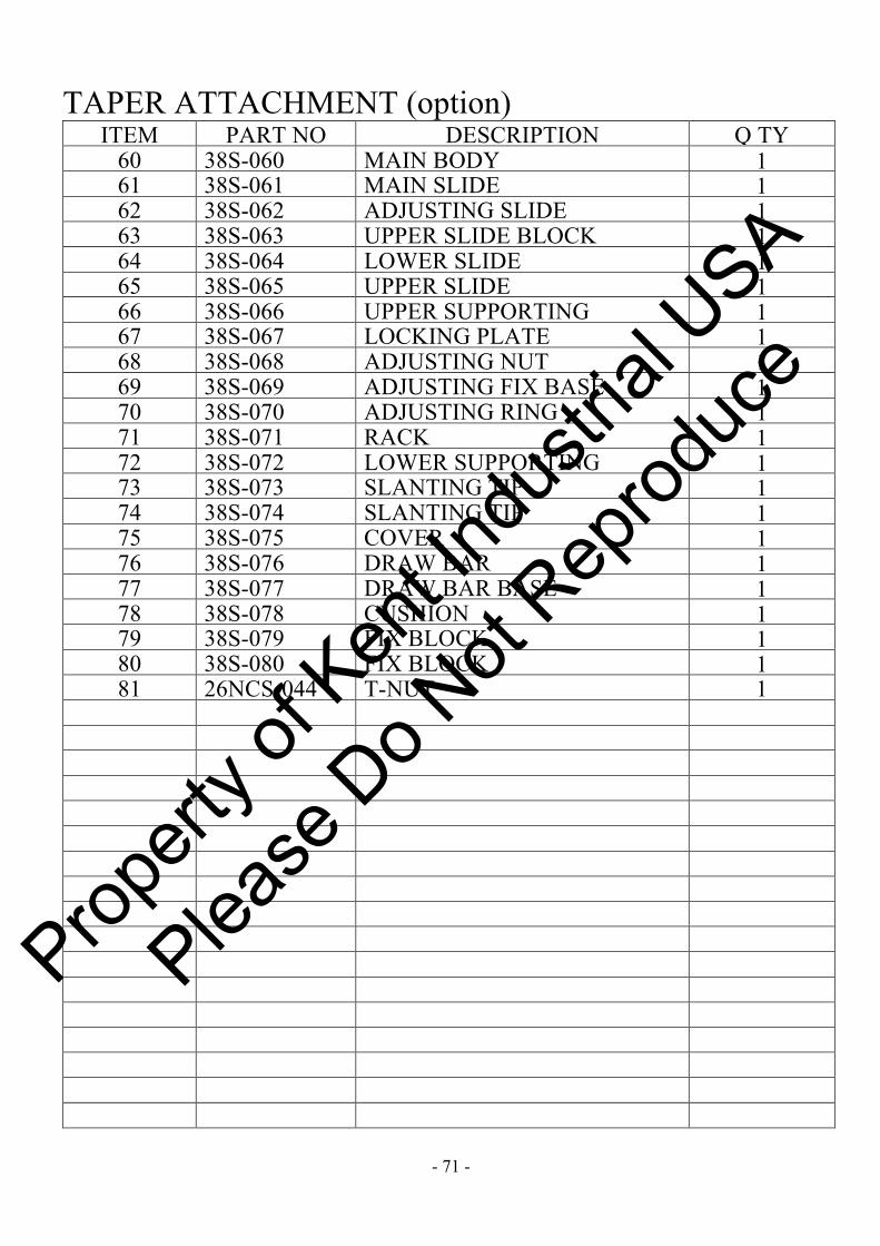
TAPER ATTACHMENT (option) ITEM PART NO DESCRIPTION Q TY
60 38S-060 MAIN BODY 1 61 38S-061 MAIN SLIDE 1 62 38S-062 ADJUSTING SLIDE 1 63 38S-063 UPPER SLIDE BLOCK 1 64 38S-064 LOWER SLIDE 1 65 38S-065 UPPER SLIDE 1 66 38S-066 UPPER SUPPORTING 1 67 38S-067 LOCKING PLATE 1 68 38S-068 ADJUSTING NUT 1 69 38S-069 ADJUSTING FIX BASE 1 70 38S-070 ADJUSTING RING 1 71 38S-071 RACK 1 72 38S-072 LOWER SUPPORTING
SHAFT 1
73 38S-073 SLANTING TIP 1 74 38S-074 SLANTING TIP 1 75 38S-075 COVER 1 76 38S-076 DRAW BAR 1 77 38S-077 DRAW BAR BASE 1 78 38S-078 CUSHION 1 79 38S-079 FIX BLOCK 1 80 38S-080 FIX BLOCK 1 81 26NCS-044 T-NUT 1
Propert
y of K
ent In
dustr
ial U
SA
Please
Do N
ot Rep
roduc
e

- 72 -
HYDRAULIC COPY DEVICE (Option)
Propert
y of K
ent In
dustr
ial U
SA
Please
Do N
ot Rep
roduc
e

- 73 -
HYDRAULIC COPY DEVICE (Option) ITEM PART NO DESCRIPTION Q TY
2 ADS-002-003 Cross slide 1 22 ADS-022-002 Compound base 1 51 ADS-051-005 Roll plate 1 74 ADS-074-001 Fixed base 1
121 ADS-121-001 Copy adjust slide 1 123 ADS-123-001 Flexible plate 1 124 ADS-124-001 Flexible pallet 1 132 ADS-132-001 Copy fixed plate 1 305 ACS-081-001 Lead screw 1 310 ACS-096-001 Cylinder bracket 1 315 ACS-122-001 Fixed base 1 316
ACS-125-001 Extension arm 1
317 ACS-126-001 Adapter boss 1 318 ACS-127-001 Cylinder bracket 1 319 ACS-128-001 Bracket 1 320 ACS-129-001 Screw 1 321 ACS-130-001 Brass nut
1
322 ACS-131-001 Spacer 1 323 ACS-133-001 Dial sleeve 1 324 ACS-135-001 Touch bar 1 327 AAS-016-N01 Dial 1 502 Bearing 51105
1
Propert
y of K
ent In
dustr
ial U
SA
Please
Do N
ot Rep
roduc
e

- 74 -
6-WAY RAPID TRAVERSE (Option)
Propert
y of K
ent In
dustr
ial U
SA
Please
Do N
ot Rep
roduc
e

- 75 -
6-WAY RAPID TRAVERSE (Option) ITEM PART NO DESCRIPTION Q TY
31 ACS-031-N02 Lead screw 1 33 ACS-033-002 Bracket 1 34 ACS-034-N02 Dial 1 35 ACS-035-002 Sleeve 1 83 ACS-083-002 Clutch 1 93 ACS-093-001 Ring 1 94 ACS-094-001 Clutch 1 95 ACS-095-001 Pulley 1
100 ACS-100-001 Fixed plate 1 101 ACS-101-001 Motor Bracket 1 102 ACS-102-001 Timing pulley 1 103 ACS-103-001 Tapered lock bush 1 301 ACE-070-001 Motor cover 1 302 ACE-071-001
Cable bracket 1
501 Bearing 51104 1 502 Bearing (TAF243216 LRT202416) 1
Propert
y of K
ent In
dustr
ial U
SA
Please
Do N
ot Rep
roduc
e

- 76 -
FOLLOW REST (Option) Prop
erty o
f Ken
t Indu
strial
USA
Please
Do N
ot Rep
roduc
e

- 77 -
FOLLOW REST (Option) ITEM PART NO DESCRIPTION Q TY
1 38S-081 HANDLE 2 2 38S-082 PIN 2 3 38S-083 SET SCREW 2 4 38S-084 WASHER 2 5 38S-085 CSATION 1 6 38S-086 LEAD SCREW 2 7 38S-087 SHAFT 2 8 38S-088 BUSH 2 9 38S-089 SET SCREW 2
10 38S-090 SCREW 2 11 38S-091 WASHER 2 12 38S-092 WASHER 2
Propert
y of K
ent In
dustr
ial U
SA
Please
Do N
ot Rep
roduc
e

- 78 -
HYDRAULIC REAR SUPPORTING STAND (Option)
Propert
y of K
ent In
dustr
ial U
SA
Please
Do N
ot Rep
roduc
e

- 79 -
HYDRAULIC REAR SUPPORTING STAND (Option) ITEM PART NO DESCRIPTION Q TY
1 38CF-001 Lathe bed 2 2 38CF-002 Fixed place 8 3 38CF-003 Fixed place 4 4 38CF-004 Slide 4 5 38CF-005 Nut place 2 6 38CF-006 Suppport place 2 7 38CF-007 Rolling cam 3 8 38CF-008 Spindle 3 9 38CF-009 Suppport place 1
10 38CF-010 Fixed place 2 11 38CF-011 Slide 2 12 38CF-012 Suppport place 1 13 38CF-013 Nut place 1 14 38CF-014 Foundation 2 15 38CF-015 Hydraulic cylinder 1 16 38CF-016 Lead screw 3 17 38CF-017 Umbrella geae 1 18 38CF-018 Umbrella geae 1 19 38CF-019 Hand wheel 1
Propert
y of K
ent In
dustr
ial U
SA
Please
Do N
ot Rep
roduc
e