operation manual - labxphotos.labwrench.com/equipmentmanuals/19834-6826.pdf · operation manual...
TRANSCRIPT

OPERATION MANUAL OM2438 Revision 6
Centra-MP4 Centrifuge Cat. No. 2437 -- For 100/120/220/240 VAC, 50/60 Hz
Centra-MP4R Refrigerated Centrifuge Cat. No. 2438 -- For 100/120/220/240 VAC, 50/60 Hz
International Equipment Company 300 Second Ave. Needham Heights, MA USA Tel. +(781) 449-8060 Fax +(781) 444-6743
1Centra MP4/MP4R Operation Manual
Table Of Contents
1 INTRODUCTION ........................................................................................................................................ 22 INSTALLATION ......................................................................................................................................... 3
2.1Receiving the Unit ............................................................................................................................... 32.2 Site Preparation .................................................................................................................... 3
Clearance Envelope ....................................................................................................... 32.3 Power Configuration .............................................................................................................. 3
Voltage .......................................................................................................................... 4Line Frequency .............................................................................................................. 4Power Cord .................................................................................................................... 4
2.4 Moving the Unit ..................................................................................................................... 52.5 The Front Panel .................................................................................................................... 5
3 OPERATION ..................................................................................................................................... 83.1 Rotor and Accessories .......................................................................................................... 8
Rotor Balance ................................................................................................................ 9Vibration ........................................................................................................................ 9Rotor Installation .......................................................................................................... 10Rotor Removal ............................................................................................................. 11Adding Rotors .............................................................................................................. 11Deleting Rotors ............................................................................................................ 11
3.2 Starting and Stopping a Run ................................................................................................ 11Manual Operation......................................................................................................... 12Momentary Mode ......................................................................................................... 12Hold Mode ................................................................................................................... 12Timing Mode ................................................................................................................ 13
3.3 Stored Programs ................................................................................................................. 13Locking Programs ........................................................................................................ 13Recall Program ............................................................................................................ 13Add/Change Program ................................................................................................... 13
3.4 Centra MP4R Refrigeration .................................................................................................. 14Rapid Condition ........................................................................................................... 14
3.5 Warning Messages and Error Codes ................................................................................... 154 APPLICATIONS ................................................................................................................................... 17
Corrosive Solvents ....................................................................................................... 174.1 Speed and Force Tables ..................................................................................................... 184.2 Derating Tables ................................................................................................................... 25
Dense Samples ........................................................................................................... 25244 Rotor ..................................................................................................................... 25
4.3 Chemical Resistance Table ................................................................................................. 274.4 Decontamination Table ........................................................................................................ 284.5 RCF Nomograph ................................................................................................................. 29
5 MAINTENANCE ................................................................................................................................... 305.1 Cleaning ............................................................................................................................. 30
Corrosion ..................................................................................................................... 31Storage ....................................................................................................................... 31Decontamination .......................................................................................................... 31
5.2 Cover Interlock Bypass ....................................................................................................... 325.3 Calibration .......................................................................................................................... 325.4 Brush Replacement ............................................................................................................ 335.5 Table of Spare Parts ........................................................................................................... 345.6 Warranty ............................................................................................................................ 345.7 Condition of Returned Equipment ......................................................................................... 355.8 Fuses Not Replaceable By The Operator ............................................................................. 35
6 SPECIFICATIONS................................................................................................................................... 36
Centra MP4/MP4R Operation Manual2
1 INTRODUCTION
The Centra MP4 and Centra MP4R are high-speed, multi-purposecentrifuges used in medical, industrial, and scientific laboratories. Thesebench-top units can achieve centrifugal forces of up to 16,750xg (using the852 rotor), and speeds up to 14,000 rpm (using the 817 rotor). The CentraMP4R provides refrigerated temperature control.
Both units accommodate a wide variety of rotors, including angle, swingingbucket, and fixed horizontal designs. They can process tubes, bottles,microplates, microcapillary tubes, cytological slide carriers, and microsampletubes. The units can centrifuge up to 1 liter of fluid in a single operation.
An easy-to-use front panel provides many versatile modes of operation:manual and pre-programmed operation, momentary spin, indefinite spin(hold mode), and a Rapid Condition (MP4R Only) function for pre-cooling orpre-warming the rotor and sample chamber. You can select gentleacceleration and deceleration rates to maintain samples with densitygradients. In addition, rotor number entry allows direct G-force controlthrough automatic calculation of RCF. With the MP4R, you can select anychamber temperature down to -5°C. Repeat runs with precisely the sametemperature, speed, and time settings may be achieved at the touch of abutton.
The internal microprocessor simplifies operation, ensures repeatable resultsfor continued success, and alerts operators when periodic maintenance isdue.
A fail-safe cover interlock ensures that the cover is closed before a run canbegin, and prevents the cover from opening until the rotor has slowed to asafe speed, even if the power fails. The rugged steel cabinet and rigidconstruction provide quiet operation and long-term reliability. A runautomatically aborts at a safe, low speed if the rotor is unbalanced.
Both units are easily configured to many different AC power sources, haveCSA certification, and are designed to meet requirements for UL listing, IEC1010, British Standard 4402 and other international standards.
3Centra MP4/MP4R Operation Manual
2 INSTALLATION
2.1 Receiving the Unit
IEC ships the centrifuge in a carton that protects it from shipping hazards.Follow the unpacking instructions on the carton. Be sure to complete thepostage-paid warranty card and return it to IEC.
2.2 Site Preparation
The Specifications in Section 6 of this manual give the dimensions of theunit. Provide clearance of 8 cm (3 inches) on each side of the unit forventilation. Place the unit on a clean and dry surface to ensure that thesuction feet grip the surface firmly. Clear the area beneath the unit of debrisand loose materials such as paper.
Clearance Envelope International Electrotechnical Commission standard 1010 part 2-20limits the permitted movement of a laboratory centrifuge to 300mm in theevent of a disruption. The user should therefore mark the clearanceenvelope boundary around the centrifuge, or laboratory managementprocedures should require that no person or any hazardous materials arewithin such a boundary while the centrifuge is operating.
The surface must be level to ensure quiet, vibration-free operation. A rigid,stable location is important since an improperly-loaded unit can vibrate oreven move.
2.3 Power Configuration
The Centra-MP4R and Centra-MP4 use AC power at 100, 120, 220, or 240Volts (nominal), at 50 or 60 Hz. The unit is shipped without fuses installedand must be configured for power at your site. Do not plug in thecentrifuge until you have configured it correctly. For best results, thecentrifuges should be used on a dedicated line. Variations in line voltage orfrequency will affect the unit’s speed and other characteristics. Less thannominal line voltage may prevent the centrifuge from reaching maximumpublished specifications of speed and/or temperature. Also, power linevoltage at some locations may sag when the refrigeration system turns on.

Caution: configuring the centrifuge incorrectly will void your warranty.
Voltage Locate the power entry module on the lower left side of the unit (Figure 2-1). On the right side of this module is the fuse drawer (Figure 2-2). A small latch on the left holds the drawer in place. Press the latch and slide the drawer out. When removing the fuse drawer, be careful that the fuses do not fall out.
Fuse Drawer
Remove and Rotate for Proper Voltage
Fuse
240
120100
220240
Power Entry Module
Latch
Fuse Drawer
Voltage Selection Window
If the number visible in the window differs from the voltage at your site, remove the square insert, rotate it, and insert it so that the correct voltage is displayed through the window. (100, 120, 220, or 240 Volts. See Section 6 Specifications for operable voltage ranges.) Install appropriate fuses for the voltage at your site as follows: For 100/120 V, install the two 16 A fuses. (IEC Part No. 50058) For 220/240 V, install the two 6.3 A fuses. (IEC Part No. 9946) Ensuring that the fuses are securely in place, reinstall the fuse drawer in the side of the centrifuge.
Line Frequency (Centra-MP4R Only). Locate the 50Hz/60Hz switch to the right of the power receptacle. Adjust this switch with a tool(screwdriver) to match the frequency at the site.
Power Cord The unit requires a grounded power supply (3-prong power outlet).If
your facility does not have properly-grounded power outlets, arrange for proper grounding.
4 Centra MP4/MP4R Operation Manual

5Centra MP4/MP4R Operation Manual
IEC provides two power cords with each Centra-MP4R and Centra-MP4.One is suitable for North America and Japan. The second has bare wires atone end for attachment of other types of plugs.
Caution: Do not remove the grounding pin from the centrifuge powercord. Do not use the bare wired power cord to attach a power plug thatdoes not have a grounding pin.
When using the power cord with bare wires, install any required plug andattach the cord to the receptacle on the lower left side of the centrifuge. Pluginto the power outlet.
Warning: The power cord(s) provided with the unit is correctly rated forthe highest current demand. This power cord should not beinterchanged with cords from equipment with lower current demand.Exchange of power cords between equipment may create a fire hazard.
2.4 Moving the Unit
Suction cups adhere the unit to the work surface and keep it from moving.This is a safety feature. To move the unit to another location, use an objectsuch as a tongue depressor under each suction cup. Lift up an edge of eachsuction cup and insert the object far enough to break the vacuum seal of thatcup. When all four cups are disengaged, the unit can be easily lifted. Whenthe unit is in its new location, ensure that the suction cups are operatingproperly again. Be sure the new location is appropriate (see Section 2.2).
The voltage and frequency settings may need to be changed at the newlocation. Check carefully that the unit is configured for the correct voltageand frequency. If necessary follow the instructions in Section 2.3.
2.5 The Front Panel
The On/Off key must be On to enable use of the front panel. This keycontrols power to the refrigeration system (MP4R)and the display. The unitdisplays the chamber temperature whenever the unit is plugged in.The On/Off key is inoperative during a run; to shut off the refrigerationsystem, first stop the run by pressing the STOP key.
The front panel contains numeric displays labeled °C (MP4R only), RPM/RCF, ROTOR/RADIUS, and MINUTES. Normally, the numeric displaysindicate actual readings of temperature, rotor speed, and the elapsed time of,or time remaining in, the run. The display instead indicates the desiredsettings for the run:
(1) whenever the up and down arrow keys are used,(2) briefly at the start of a run, and(3) briefly after the unit is switched on.
When the display shows actual readings, the numbers are bright; when thedisplay shows desired settings, the numbers are dim.
Centra MP4/MP4R Operation Manual6
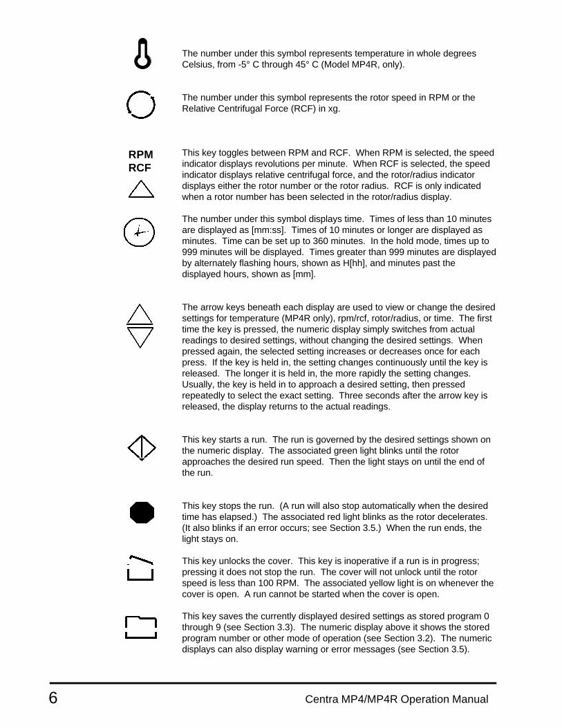
The number under this symbol represents temperature in whole degreesCelsius, from -5° C through 45° C (Model MP4R, only).
The number under this symbol represents the rotor speed in RPM or theRelative Centrifugal Force (RCF) in xg.
This key toggles between RPM and RCF. When RPM is selected, the speedindicator displays revolutions per minute. When RCF is selected, the speedindicator displays relative centrifugal force, and the rotor/radius indicatordisplays either the rotor number or the rotor radius. RCF is only indicatedwhen a rotor number has been selected in the rotor/radius display.
The number under this symbol displays time. Times of less than 10 minutesare displayed as [mm:ss]. Times of 10 minutes or longer are displayed asminutes. Time can be set up to 360 minutes. In the hold mode, times up to999 minutes will be displayed. Times greater than 999 minutes are displayedby alternately flashing hours, shown as H[hh], and minutes past thedisplayed hours, shown as [mm].
The arrow keys beneath each display are used to view or change the desiredsettings for temperature (MP4R only), rpm/rcf, rotor/radius, or time. The firsttime the key is pressed, the numeric display simply switches from actualreadings to desired settings, without changing the desired settings. Whenpressed again, the selected setting increases or decreases once for eachpress. If the key is held in, the setting changes continuously until the key isreleased. The longer it is held in, the more rapidly the setting changes.Usually, the key is held in to approach a desired setting, then pressedrepeatedly to select the exact setting. Three seconds after the arrow key isreleased, the display returns to the actual readings.
This key starts a run. The run is governed by the desired settings shown onthe numeric display. The associated green light blinks until the rotorapproaches the desired run speed. Then the light stays on until the end ofthe run.
This key stops the run. (A run will also stop automatically when the desiredtime has elapsed.) The associated red light blinks as the rotor decelerates.(It also blinks if an error occurs; see Section 3.5.) When the run ends, thelight stays on.
This key unlocks the cover. This key is inoperative if a run is in progress;pressing it does not stop the run. The cover will not unlock until the rotorspeed is less than 100 RPM. The associated yellow light is on whenever thecover is open. A run cannot be started when the cover is open.
This key saves the currently displayed desired settings as stored program 0through 9 (see Section 3.3). The numeric display above it shows the storedprogram number or other mode of operation (see Section 3.2). The numericdisplays can also display warning or error messages (see Section 3.5).
RPMRCF

7Centra MP4/MP4R Operation Manual
The rotor/radius display indicates either the selected rotor number or therotor radius in centimeters. This display illuminates when the rotor isselected. The applicable IEC rotor numbers are supplied in the memory,along with their maximum radius in centimeters. The key under rotor/radiustoggles between the two. To select a rotor number, toggle to ROTOR andpress an arrow key under the rotor display. To change the radius, toggle toRADIUS, and press an arrow key under the rotor display. Note that theradius cannot be changed to a radius larger than the maximum radius for thatrotor. The display changes back to rotor number after three seconds.
Gentle acceleration and braking can be selected when centrifuging delicatesamples. The gentle settings avoid mixing of density gradients or breakup ofpellets.
This key controls rotor acceleration up to 400 RPM. If the yellow light overthe rabbit is lit, then full acceleration is selected. If the yellow light over theturtle is lit, then slow acceleration is selected. Slow acceleration takes from15 to 35 seconds to achieve 400 RPM, depending on the rotor and itscontents.
This key controls rotor braking. If the yellow light over the rabbit is lit, fullbraking is selected. If the yellow light over the turtle is lit, slow braking isselected. (This means the rotor will coast down from 600 RPM.) If bothlights are out, all braking is disabled; the rotor will coast from operating speedto a stop.
Centra MP4/MP4R Operation Manual8
3 OPERATION
3.1 Rotor and Accessories
A balanced load is essential with all centrifuges. An unbalanced loadproduces vibration and can damage the unit. A 2 gram load imbalance, at aspeed of 4600 RPM, imparts force equivalent to 9.1 kg at rest (20 pounds).Therefore, always ensure that the rotor is loaded symmetrically with a fullcomplement of accessories, and a full (or paired) set of tubes. Tubeadapters should also be installed symmetrically.
IEC rotors are dynamically balanced at the factory. IEC matches removableparts (trunnion rings, shields, buckets and carriers) to within 1 gram andstamps the weight on each piece. Check these markings whenever youinterchange parts, to ensure that opposite parts are matched. Ensure thatthe total weight of samples and removable parts loaded in opposing positionsare equal in weight to within 1 gram. The position numbers, present on manyrotors and adapters, identify opposing tube positions.
To obtain good dynamic balance, the opposite loads must not only be equalin mass, but must also have the same center of gravity. Opposing containersmust be alike in shape, thickness, and distribution of glass or plastic. This isespecially important for large containers.
Tubes loaded into swinging bucket rotors must be symmetric around the axisof rotation. Verify this by rotating the entire rotor 180° by hand: the loadsshould be in the same apparent positions (not in the mirror image). Inaddition, the loads within each bucket must also be symmetric around thebucket’s pivot axis. Verify this by ensuring that each bucket is loaded so thatit does not tilt from the vertical when the rotor is at rest. Maintaining balancewithin each bucket ensures that the bucket and the tubes swing out tohorizontal when the rotor reaches operating speed, applying centrifugal forcetoward the bottom of the tubes. Failure to achieve full swing-out causesvibration and premature wear of both the rotor and the motor.
Samples of like (similar) specific gravities may be processed in the same runprovided the samples of the same type are balanced around the rotor asthough they were the only pairs in the rotor.
Caution: DO NOT exceed maximum rated speed for each rotor/accessory combination. Maximum rated speeds can befound in Section 4.1 Speed And Force Tables.
9Centra MP4/MP4R Operation Manual
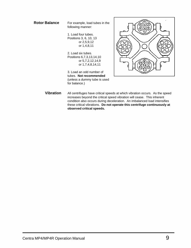
Rotor Balance For example, load tubes in thefollowing manner:
1. Load four tubes.Positions 3, 6, 10, 13
or 2,5,9,12or 1,4,8,11
2. Load six tubes.Positions 6,7,3,13,14,10
or 5,7,2,12,14,9or 1,7,4,8,14,11
3. Load an odd number oftubes. Not recommended(unless a dummy tube is usedfor balance.)
Vibration All centrifuges have critical speeds at which vibration occurs. As the speedincreases beyond the critical speed vibration will cease. This inherentcondition also occurs during deceleration. An imbalanced load intensifiesthese critical vibrations. Do not operate this centrifuge continuously atobserved critical speeds.
Rotor Installation To install a rotor, line up the keyway (slot) in the rotor with the key in the shaft. Lower the rotor straight onto the shaft. A correctly aligned rotor will slide down far enough that the shaft protrudes through the top of the rotor. Secure the locking nut onto the shaft using the wrench provided. Caution: Failure to securely tighten the rotor retaining nut against the rotor WITH THE WRENCH PROVIDED will result in the rotor coming off the shaft. The 851, 852 and 853 rotors require an IEC Part No. 50036 hub adapter. Use the wide rotor locking nut to secure the rotor to the tapered hub adapter. For easiest use, leave the rotor and hub adapter secured together when installing and removing. Use the locking nut to secure the hub adapter to the shaft, and tighten with a coin or tool. Caution: Never remove the key from the shaft in order to use a non-standard rotor; equipment failure can result.
10 Centra MP4/MP4R Operation Manual

11Centra MP4/MP4R Operation Manual
Rotor Removal To remove a rotor, first remove any sample tubes, shields, buckets andother accessories from the rotor. Unscrew and remove the locking nut. If therotor is difficult to remove, place the locking nut back on the shaft and fingertighten it. Unscrew it one turn. Grasp the rotor with one hand and pull upwardon it while tapping the locking nut with the locking wrench. The opposingforce should free the rotor to be lifted from the shaft.
Adding Rotors As new rotors are released by IEC, the rotor number and radius can beadded to the rotor menu. To do so, press the hidden key located behind the“C” in IEC. Prog x.x will appear. Press RPM arrows until "rotor Add"appears. Press the file key and "Rotor" will appear next to the Rotor/Radiusdisplay. Press an arrow key under the rotor display to select the new rotornumber. Press the file key. "Radius" appears. Use arrow keys to selectmaximum radius. Press file key again. "RPM" will be illuminated. Use theRPM arrow key to select the maximum RPM for the rotor. Push file again.Unit beeps three times to acknowledge addition of rotor. Press "C" in IEC toreturn to normal operation. Note: Up to five rotors may be added to memory.When the rotor memory is full, the unit displays "FUL" under the rotorsymbol.
Deleting Rotors Push "C" in IEC. Use RPM arrows to scroll to "rotor Add." Use thetime arrows to select "dEL" instead of "Add." Press file key. "Rotor"appears. Use rotor arrows to select rotor to be deleted. Press file key todelete. Unit beeps three times to acknowledge deletion of rotor.
3.2 Starting and Stopping a Run
Read Section 2.5 for a general description of the front panel. The desiredsettings displayed on the front panel always govern the operation of the unit.The number or symbol displayed above the word PROGRAM describes theoperating mode of the unit. It is important that the unit be in the correct modefor the desired operation.
The digits and symbols, which appear above the word PROGRAM when thearrow keys are pressed, can be one of the following:
blank The unit is in manual operation.
0-9 The unit is under control of the stored program with the numbershown.
H The unit is set to hold mode, in which it runs until you stop it.
- The unit is set for a momentary spin.
C The unit is set to Rapid Condition, a special program discussed inSection 3.4.
The display indicates the parameters last selected for each PROGRAMmode of operation.
Centra MP4/MP4R Operation Manual12
Manual Operation For manual operation, set the mode so that the display above the wordPROGRAM is blank. Select a desired temperature (MP4R only), speed/g-force, run time, acceleration mode, and deceleration mode. To start the spin,press the Start key. The spin stops automatically at the end of the desiredinterval. A run can also be stopped manually by pressing the STOP key.
During a manual operation, the MINUTES display counts down and displaysthe time remaining in the current spin.
The run time specified begins either when the START key is pressed, orwhen the rotor reaches 95% of set speed (see TIMING MODE). When theelapsed time reaches this desired setting, deceleration begins. That is, therun time does not include deceleration time.
The settings can be changed during a manual run. These changes affectthe run in progress. If the time setting is changed during a run, the unitadjusts the displayed count-down timer so that your revised setting will bethe total time of the run. If the new time selected is less than the elapsedtime, the run will end.
The unit’s mode (PROGRAM) cannot be changed during a spin.
Momentary Mode Momentary spin is useful for easily separated samples, for simultaneousmixing of samples, and to deposit condensate droplets at the bottom of thetube.
For momentary spin, set the mode so that a dash “-” appears above the wordPROGRAM. The dash also appears above MINUTES because there is noprogrammed time in a momentary spin. Select temperature (MP4R only),speed/g-force, acceleration mode, and deceleration mode, as for manualoperation.
Press and hold the START key. The run starts when you press the key andends when you release the key. In this mode you can perform very quickseparations or protocols.
During a momentary spin, the unit displays actual values, not desiredsettings. The MINUTES display counts upward and displays the elapsedtime since you pressed the START key.
Hold Mode For hold mode (operation without time limit), set the mode so that H appearsabove the word PROGRAM. The H also appears above MINUTES becausehold mode does not have a programmed time.
Select temperature (MP4R only), speed/g-force, acceleration mode, anddeceleration mode, as for manual operation. Press and release the STARTkey. The run starts when you press the key and stops only when you pressthe STOP key. Hold mode is like manual operation, except that the timesetting is not used. During a run in hold mode, the MINUTES display countsupward and displays the elapsed time of the spin. See Section 2.5 for moreinformation on the MINUTES display operation.

13Centra MP4/MP4R Operation Manual
Timing Mode Two timing modes are available on these units:
ACC, for the set time to start counting down at the beginning of acceleration;that is, when the start key is pressed. The unit is originally set to this mode.SPd, for the set time to start counting down when the rotor has reached 95%of set speed. Display will alternately display set time and SPd until countingbegins.
To select a timing mode, press the TIME down arrow key , and scroll belowzero. ACC or SPd will appear. Press and release the TIME down arrow keyto choose the desired mode. After three seconds, or after pressing the FILEor START key, the display will return to the last selected run time providedthe up arrow key has not been pressed.
The timing mode is stored along with the other parameters when a programis saved. If a saved program has been recalled, altered, and not re-saved,the timing mode will revert back to the previous mode when recalled.
3.3 Stored Programs
The Centra-MP4 series has an internal memory capable of holding 10 sets ofrun parameters. Each set, or program, is stored and can be recalled byselecting a program number (0 - 9). Programs are retained in memory evenif the power is turned off. When necessary, a program can be modified for aparticular run or changed permanently. You cannot change the unit'sprogram, rotor/radius, or timing modes during a spin.
Locking Programs Programs can be locked from the program lock in the special functionmenu. Press the "C" in IEC. Use RPM arrows to scroll until "Loc P" isdisplayed. Use the program arrow keys to select the program to be locked.Pressing the following keys in the following order will lock or unlock aprogram: Start, Stop, Cover Open, Stop, Start and File (Save). The displaywill alternate between the program number and an "L" indicating that thevalues of the program are locked and cannot be changed.
Recall Program Press a program arrow key to select the appropriate program number.The programmed run parameters will be displayed and will become the setparameters. To begin this run, simply press START.
Add/Change Program Select a program number with the program arrow keys. The currentprogram parameters will appear on the display. Modify the desiredparameters using the parameter arrow keys, or the ACCEL or BRAKEswitches. To make the changes permanent, press the PROGRAM SAVE(file folder) key. The program number will stop flashing, and the new programwill be displayed and will remain in memory until further changes are made.To make changes temporary, press START without pressing the PROGRAMSAVE (file folder) key. The program display goes blank to indicate that thevalues are now stored in the manual program and the instrument is notoperating from the program mode at this time. As long as the PROGRAMSAVE (file folder) key is not pressed, the original program remainsunchanged.
Centra MP4/MP4R Operation Manual14
3.4 Centra MP4R Refrigeration
Whenever the cover is closed and the unit is switched ON, the unit appliesrefrigeration to the rotor chamber as necessary to cool it to the currentlydisplayed temperature setting. However, using the keyboard so that a coldtemperature is momentarily displayed (for example, stepping through thestored programs) does not activate refrigeration.
If a temperature higher than ambient is specified, the unit does not heat therotor chamber except through the normal heating effect of the equipment(i.e. air friction and motor heat).
If the rotor chamber is not at the temperature specified, it does not abort thespin. However, if the rotor chamber differs by 5°C or more from the specifiedtemperature at the start of a run, the unit sounds an audible alarm (seeSection 3.5). The °C display switches between the actual and programmedtemperature until the two temperatures come within 5°C. This shows thereason for the alarm. Press the STOP key if the run should not continue atthe actual temperature.
The unit is not designed for use as a refrigerator. The natural fanning actionof the rotating horizontal and fixed angle rotors serves to maintain a uniformtemperature distribution inside the chamber. Therefore, at zero RPM, thereis no correlation between set and actual chamber temperatures.
Any frost or condensation that forms in the rotor chamber should be removedby allowing it to melt and removing it with a sponge or cloth. When thecentrifuge is not in use, turn it off or leave the cover open (disablingrefrigeration).
Rapid Condition When the chamber temperature is above the set temperature, RAPID (MP4R Only) CONDITION will run a rotor at 500 rpm to increase air circulation in the
chamber to quickly cool the chamber to the set point. When the chambertemperature is below the set temperature, RAPID CONDITION will run therotor at 3400 rpm to warm the chamber to the set temperature. When thetemperature has been reached a three beep signal will sound and the rotorwill brake to rest. (Some smaller rotors may not be able to warm thechamber to the higher temperature settings.) To select this program, pressthe PROGRAM arrow keys until a 'C' appears in the PROGRAM display.Select the desired temperature, install a rotor, and press the START key.
15Centra MP4/MP4R Operation Manual
3.5 Warning Messages and Error Codes
The beeper sounds in these situations:
o Briefly whenever a key is pressed.
o Three times at the start and at the end of a spin.
o On the Centra-MP4R for 2 seconds if the START key is pressed andthe rotor chamber is more than 5° C warmer or cooler than yourdesired temperature setting (see Section 3.4).
o Seven times when a warning occurs (see below).
Warning Messages appear in place of the numeric displays in the followingcases:
bAL This appears during a run if the rotor is unbalanced. Therotor brakes to a stop and the run ends. The cover must beopened to reset this warning. Verify that a balanced load isinstalled. Inspect the rotor and rearrange tubes or addadditional, inactive tubes to balance the rotor.
HEAd This appears if you start a run without loading a rotor into thechamber. The run ends. The cover must be opened to resetthis warning.
LId This appears briefly if you press the Start key but the coveris not closed. Closing the cover resets the warning.
PFAIL This appears at the end of a run that is interrupted by apower failure. Opening the cover resets this warning.
bruSh This appears at the end of every run if it is time to replacethe brushes. To reset the warning and replace the brushes,see Section 5.4.
LInE LO/HI This appears as soon as power is applied to the unit if theline voltage does not match the voltage configuration. It canonly be cleared by unplugging the unit and reconfiguring itproperly (see Section 2.3).
Warning Messages during a spin. The “bAL”, “LId”, and “PFAIL”messages can occur during a spin. In this case, the rotor brakes to a stopand the run ends.
Error Codes require factory-authorized maintenance. A typical error meansthe internal microprocessor has detected impermissible readings or a failureelsewhere in the unit. An error number appears on the front panel. Tell theservice personnel which number appeared when you report the problem.
Centra MP4/MP4R Operation Manual16
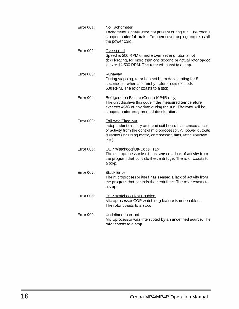
Error 001: No TachometerTachometer signals were not present during run. The rotor isstopped under full brake. To open cover unplug and reinstallthe power cord.
Error 002: OverspeedSpeed is 500 RPM or more over set and rotor is notdecelerating, for more than one second or actual rotor speedis over 14,500 RPM. The rotor will coast to a stop.
Error 003: RunawayDuring stopping, rotor has not been decelerating for 8seconds, or when at standby, rotor speed exceeds600 RPM. The rotor coasts to a stop.
Error 004: Refrigeration Failure (Centra MP4R only)The unit displays this code if the measured temperatureexceeds 45°C at any time during the run. The rotor will bestopped under programmed deceleration.
Error 005: Fail-safe Time-outIndependent circuitry on the circuit board has sensed a lackof activity from the control microprocessor. All power outputsdisabled (including motor, compressor, fans, latch solenoid,etc.).
Error 006: COP Watchdog/Op-Code TrapThe microprocessor itself has sensed a lack of activity fromthe program that controls the centrifuge. The rotor coasts toa stop.
Error 007: Stack ErrorThe microprocessor itself has sensed a lack of activity fromthe program that controls the centrifuge. The rotor coasts toa stop.
Error 008: COP Watchdog Not EnabledMicroprocessor COP watch dog feature is not enabled.The rotor coasts to a stop.
Error 009: Undefined InterruptMicroprocessor was interrupted by an undefined source. Therotor coasts to a stop.

17Centra MP4/MP4R Operation Manual
4 APPLICATIONS
This section describes the use of specific rotors and accessories. Moredetailed information is often shipped with the rotor or accessory itself. Thissection contains five reference tables:
o Speed and Force Tableso Derating Table for Dense Sampleso Chemical Resistance Tableo Decontamination Tableo Nomograph
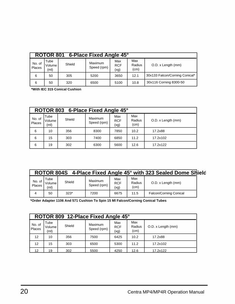
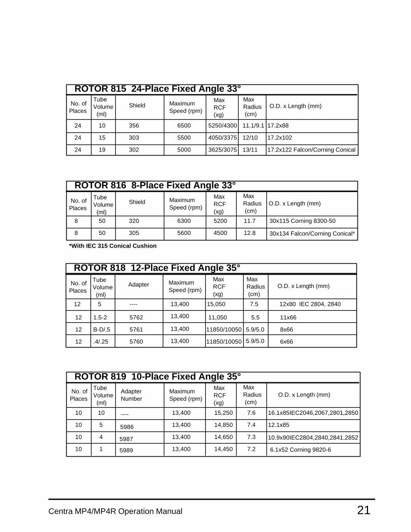
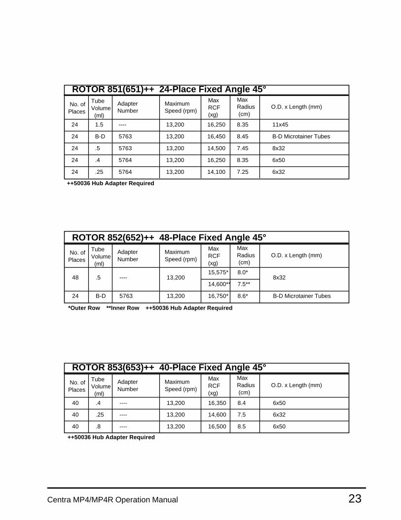
Relative centrifugal force (RCF or G-force) at a given speed varies with therotor, and with the length of the sample tube, because the distance of thetube’s tip from the center of rotation is different. The Speed and ForceTables indicate the maximum speed and RCF the Centra MP4 and theCentra MP4R can achieve with various rotor/accessory combinations. TheDerating Table specifies reductions in maximum RPM when spinningsamples with specific gravity above 1.2.
Misapplication of any tube can cause tube rupture. To avoid this, comparethe G forces specified in the Speed and Force Table with the ratings for thetubes you are using. If the tubes are not rated for the force the centrifuge willapply, reduce the speed to the G-force listed for your tubes.
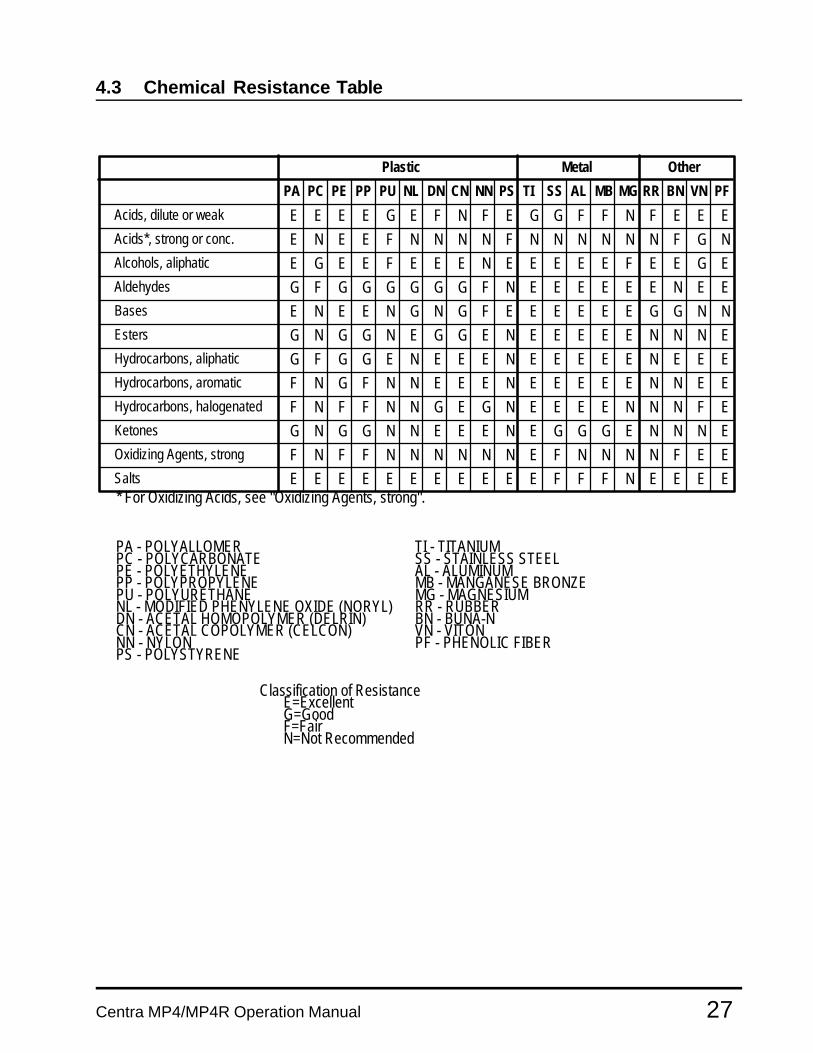
Corrosive Solvents Your IEC centrifuge is made of materials designed to resist attack from mostlaboratory chemicals. The interior of the rotor chamber is stainless steel.Rotors and accessories placed in the chamber are made of a variety ofmaterials, including aluminum and polypropylene. The Chemical ResistanceTable shows the suitability of each material with different classes of reagents.
Section 5.1 describes how to clean and remove corrosion from the chamber,rotors, and accessories. Follow these instructions, and clean spills promptly,to minimize the effect of corrosive chemicals and to avoid expensive repairs.
Centra MP4/MP4R Operation Manual18
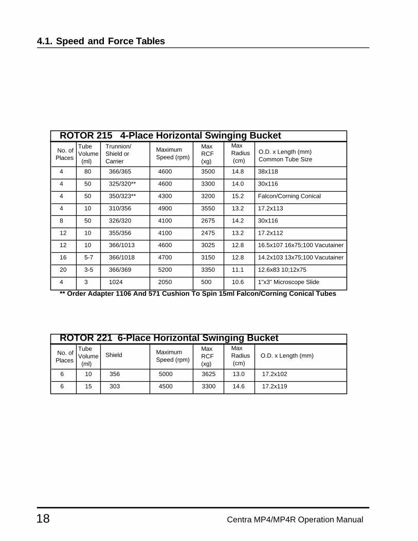
4.1. Speed and Force Tables
ROTOR 221 6-Place Horizontal Swinging Bucket No. of Places
Tube Volume (ml)
Shield Maximum Speed (rpm)
Max RCF (xg)
Max Radius (cm)
O.D. x Length (mm)
6
6
10
15
356
303
5000
4500
3625
3300
13.0
14.6
17.2x10²
17.2x119
No. of Places
Tube Volume (ml)
Trunnion/ Shield or Carrier
Maximum Speed (rpm)
Max RCF (xg)
Max Radius (cm)
O.D. x Length (mm)
ROTOR 215 4-Place Horizontal Swinging Bucket
4
4
4
4
80
50
50
10
50
10
8
12
12
16
20
4
10
5-7
3-5
3 1024
366/369
366/1018
366/1013
355/356
326/320
310/356
350/323**
325/320**
366/365 4600
4600
4600
4300
4900
4100
4100
4700
5200
2050
3500
3300
3200
3550
2675
2475
3025
3150
3350
500
14.8
14.0
15.2
13.2
14.2
13.2
12.8
12.8
11.1
10.6
38x118
30x116
Falcon/Corning Conical
17.2x113
30x116
17.2x112
16.5x10⁷ 16x75;100 Vacutainer
14.2x10³ 13x75;100 Vacutainer
12.6x83 10;12x75
1"x3" Microscope Slide
** Order Adapter 1106 And 571 Cushion To Spin 15ml Falcon/Corning Conical Tubes
Common Tube Size

19Centra MP4/MP4R Operation Manual
ROTOR 794 4-Place Fixed Horizontal No. of Places
Tube Volume (ml)
Tray Insert
Maximum Speed (rpm)
Max RCF (xg)
Max Radius (cm)
O.D. x Length (mm)
40
40
.25-.4
1.5-2
5914
5912
12,800
12,800
11,000
11,000 6.0
4.7-6.0 6.0x46 Microtubes
11.0x39 Microtubes
No. of Places
Tube Volume (ml)
Maximum Speed (rpm)
Max RCF (xg)
Max Radius (cm)
O.D. x Length (mm)
ROTOR 796 6-Place Fixed Horizontal
60
60
.25-.4
1.5-2
5914
5912
Tray Insert
9000
9000
6350
6350
5.7-7.0
7.0
6.0x46 Microtubes
11.0x39 Microtubes
86x128 (96 well) Array Racks
ROTOR 244 2-Place (Tray) Horizontal Microplate No. of Places
Maximum Speed (rpm)
Max RCF (xg)
Max Radius (cm)
O.D. x Length (mm)Tube Volume (ml)
2 ----
Carrier
49852 4,000* 1800 10.0
*Speed Limited
Falcon 2076 w/2090 cushion
ROTOR 224 Horizontal Swinging Bucket with Cat. No. 3224 Cups No. of Places
Tube Volume (ml)
Adapter Number
Maximum Speed (rpm)
Max RCF (xg)
Max Radius (cm)
O.D. x Length (mm)
4 250 ----
4 50 7231
12
16
30 7223
15 7230
4400
4400
4400
4400
440028 15 7224
4400
3310
3180
3180
3180
3180
28 10-15 7225 3180
40
40
48
40 7
3-5
3
1.5 7228
7228
7226
7236 4400
4400
4400
4400 2970
3180
3180
3180
13.7
14.7
14.7
14.7
14.7
14.7
15.1
14.7
14.7
15.3 IEC 2050, 2051
Falcon/Corning Conical
Falcon/Corning Conical
IEC 2047, 2055, 2802
16.2x100
13;16x75;100 Vacutainer/HG
13x100 Vacutainer
12x75; 10x75
10x50
1.5 Microtube
175 ----4 4400 3270 15.1
4 80 7221 4400 3180 14.7 38.1x111
Common Tube Size
*See Derating Table For 244 Rotor
11,000 8,120
11,000 8,120
Centra MP4/MP4R Operation Manual20
ROTOR 809 12-Place Fixed Angle 45° No. of Places
Tube Volume (ml)
Maximum Speed (rpm)
Max RCF (xg)
Max Radius (cm)
O.D. x Length (mm)Shield
12
12
12
7500
6500
5500
6425
5300
4250
10.2
11.2
12.6
17.2x88
17.2x10²
17.2x122
10
15
19
356
303
302
No. of Places
Tube Volume (ml)
Shield Maximum Speed (rpm)
Max RCF (xg)
Max Radius (cm)
O.D. x Length (mm)
ROTOR 803 6-Place Fixed Angle 45°
6
6
6
10
15
19
356
303
302
8300
7400
6300
7850
6850
5600
10.2
11.2
12.6
17.2x88
17.2x10²
17.2x122
No. of Places
Tube Volume (ml)
Maximum Speed (rpm)
Max RCF (xg)
Max Radius (cm)
O.D. x Length (mm)Shield
ROTOR 801 6-Place Fixed Angle 45°
6
6
50
50
305
320
5200
6500
3650
5100
12.1
10.8
30x133 Falcon/Corning Conical*
30x116 Corning 8300-50
*With IEC 315 Conical Cushion
No. of Places
Tube Volume (ml)
Shield Maximum Speed (rpm)
Max RCF (xg)
Max Radius (cm)
O.D. x Length (mm)
ROTOR 804S 4-Place Fixed Angle 45° with 323 Sealed Dome Shields
4 50 323* 7200 6675 11.5 Falcon/Corning Conical
*Order Adapter 1106 And 571 Cushion To Spin 15 Ml Falcon/Corning Conical Tubes
21Centra MP4/MP4R Operation Manual
ROTOR 819 10-Place Fixed Angle 35° No. of Places
Tube Volume (ml)
Adapter Number
Maximum Speed (rpm)
Max RCF (xg)
Max Radius (cm)
O.D. x Length (mm)
----
5986
5987
5989
10
10
10
10
10
1
5
4
13,400
13,400
13,400
13,400
15,250
14,850
14,650
14,450
7.6
7.4
7.3
7.2
16.1x85IEC2046,2067,2801,2850
12.1x85
10.9x90IEC2804,2840,2841,2852
6.1x52 Corning 9820-6
10
15
19
356
303
302
ROTOR 815 24-Place Fixed Angle 33° No. of Places
Tube Volume (ml)
Maximum Speed (rpm)
Max RCF (xg)
Max Radius (cm)
O.D. x Length (mm)Shield
24
24
24
6500
5500
5000
5250/4300 11.1/9.1
4050/3375 12/10
3625/3075 13/11
17.2x88
17.2x10²
17.2x122 Falcon/Corning Conical
No. of Places
Maximum Speed (rpm)
Max Radius (cm)
O.D. x Length (mm)
ROTOR 818 12-Place Fixed Angle 35°Tube Volume (ml)
Max RCF (xg)
12
12
12
12
5
1.5-2
B-D/.5
.4/.25
----
5762
5761
5760
Adapter
13,400
13,400
13,400
13,400
15,050
11,050
11850/10050
11850/10050
7.5
5.5
5.9/5.0
5.9/5.0
12x80 IEC 2804, 2840
11x66
8x66
6x66
No. of Places
Tube Volume (ml)
Maximum Speed (rpm)
Max RCF (xg)
Max Radius (cm)
O.D. x Length (mm)Shield
ROTOR 816 8-Place Fixed Angle 33°
8
8
50
50
320
305
6300
5600
5200
4500
11.7
12.8
30x115 Corning 8300-50
30x134 Falcon/Corning Conical*
*With IEC 315 Conical Cushion

Centra MP4/MP4R Operation Manual22
No. of Places
Tube Volume (ml)
Adapter Number
Maximum Speed (rpm)
Max RCF (xg)
Max Radius (cm)
O.D. x Length (mm)
ROTOR 836 6-Place Fixed Angle 30°
6
6
6
6
30
15
5
3
----
5965
5966
5967
13,400
13,400
13,400
13,400
15,050
14,450
14,050
13,650
7.5
7.2
7.0
6.8
25.8x100 IEC 2047,2055,2802
16.1x10⁹
12.1x112
10.9x95
No. of Places
Adapter Number
Maximum Speed (rpm)
Max RCF (xg)
Max Radius (cm)
O.D. x Length (mm)
ROTOR 841 12-Place Fixed Angle 45°Tube Volume (ml)
12
12
12
12
12
1.5-2
B-D
.5
.4
.25
----
5763
5763
5764
5764
14,000
14,000
14,000
14,000
14,000
12,700
12,700
12,925
10,750
9850
5.8
5.9
4.9
5.8
4.5
11x39
B-D Microtainer Tubes
8x66
6x46
6x46
23Centra MP4/MP4R Operation Manual
ROTOR 851(651)++ 24-Place Fixed Angle 45°
No. of Places
Tube Volume (ml)
Adapter Number
Maximum Speed (rpm)
Max RCF (xg)
Max Radius (cm)
O.D. x Length (mm)
24
24
24
24
24
1.5
.5
.4
.25
----
5763
5763
5764
5764
13,200
13,200
13,200
13,200
13,200
16,250
16,450
14,500
16,250
14,100
8.35
8.45
7.45
8.35
7.25
11x45
B-D Microtainer TubesB-D
8x32
6x50
6x32
ROTOR 852(652)++ 48-Place Fixed Angle 45°
No. of Places
Tube Volume (ml)
Adapter Number
Maximum Speed (rpm)
Max RCF (xg)
Max Radius (cm)
O.D. x Length (mm)
48
24
----
5763
13,200
13,200 B-D Microtainer TubesB-D
.58.0*
7.5**
15,575*
14,600**8x32
16,750* 8.6*
*Outer Row **Inner Row ++50036 Hub Adapter Required
ROTOR 853(653)++ 40-Place Fixed Angle 45°
No. of Places
Tube Volume (ml)
Adapter Number
Maximum Speed (rpm)
Max RCF (xg)
Max Radius (cm)
O.D. x Length (mm)
---- 13,200
13,200
40
40
40
----
----
.4
.25
.8
13,200
16,350
14,600
16,500
8.4
7.5
8.5
6x50
6x32
6x50
++50036 Hub Adapter Required
++50036 Hub Adapter Required

Centra MP4/MP4R Operation Manual24
ROTOR 854 4-Place Fixed Angle 20°
No. of Places
Tube Volume (ml)
Adapter Number
Maximum Speed (rpm)
Max RCF (xg)
Max Radius (cm)
O.D. x Length (mm)
4 ----
4
4
4
30
30
25
7243
50
Corning 8446-AO
Corning 8445-AO
12,900
12,100
12,100
14,000
12,900
12,200
12,200
13,400
7.53
7.2
7.2
7.2
28.4x10⁶ IEC1630,2048,2053,2997
25.4x93 IEC 2047,2055,2802
Corning 8445-30
Corning 8446-25

25Centra MP4/MP4R Operation Manual
4.2 Derating Tables
Dense Samples The Speed and Force Table lists the maximum speed for each rotor/adaptercombination in the Centra-MP4/R. These speeds are guaranteed only withsamples whose specific gravity is not greater than:
1.2 for swinging bucket rotors1.5 for fixed angle rotors
For denser samples, the maximum guaranteed speed is reduced (derated)by a factor from the table below:
Derating Factor for:
Specific Gravity Swinging Bucket Fixed Angle1.2 1. 1.1.3 .960 1.1.4 .925 1.1.5 .894 1.1.6 .866 .9671.7 .839 .9391.8 .816 .9121.9 .794 .8882.0 .774 .8662.1 .755 .8442.2 .738 .8252.3 .721 .8072.4 .707 .7902.5 .692 .7742.6 .678 .7582.7 .666 .7442.8 .654 .7312.9 .642 .7193.0 .632 .707
Example. An angle rotor rated for 10,000 RPM, used with samples with aspecific gravity of 1.6, cannot spin faster than (10,000 x .967 =) 9,670 RPM.
Specific gravities greater than 3.0. This table is based on the formula:√ (s
0/s
a)
...where s0 is the maximum specific gravity allowed before derating (1.2 or 1.5,
depending on the type of rotor), and sa is the actual specific gravity of the
sample in question. You can use the same formula to compute deratingfactors for specific gravities greater than 3.0.
Caution: Do not exceed the rated speed. Higher speeds willimpose unnecessary wear on the centrifuge and cancause ROTOR FAILURE.
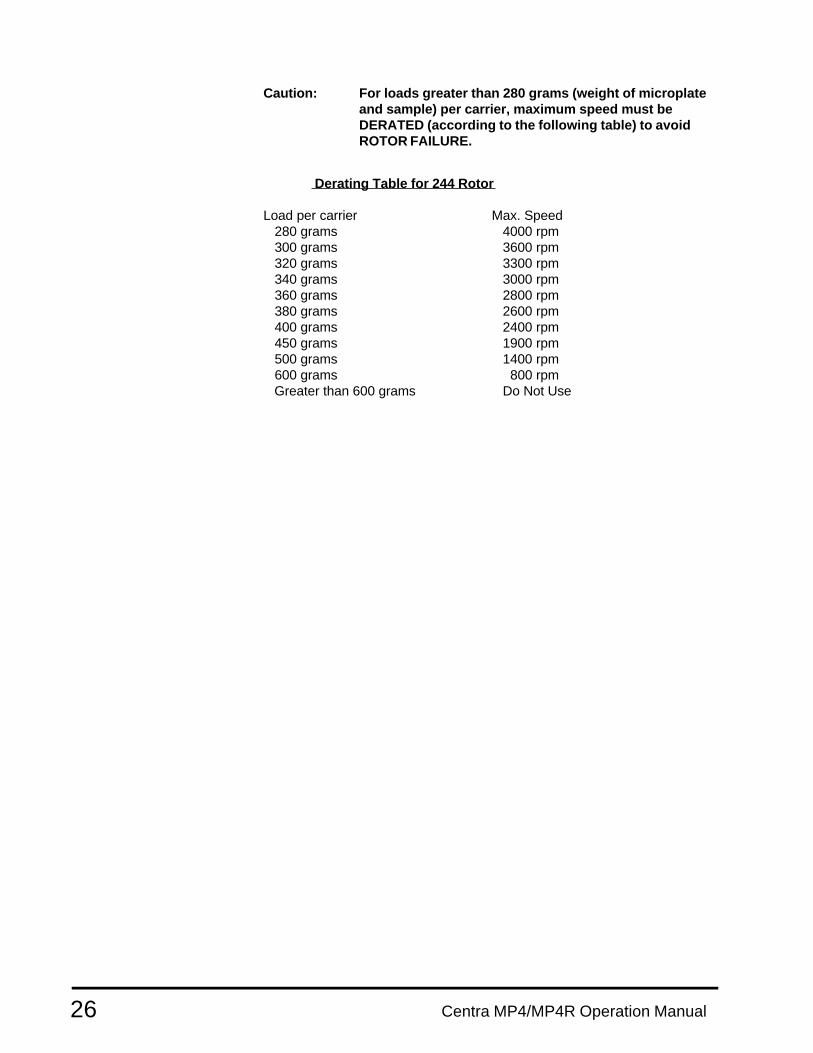
244 Rotor The 244 rotor is designed for centrifugation of multi-well microplates.The weight of the loaded microplates must be equally distributed betweenthe rotor's two carriers. The maximum rated speed for the 244 rotor wheneach of the carriers is loaded with 280 grams (total load of 560 grams) is4000 rpm in the MP4/R.
Centra MP4/MP4R Operation Manual26
Caution: For loads greater than 280 grams (weight of microplateand sample) per carrier, maximum speed must beDERATED (according to the following table) to avoidROTOR FAILURE.
Derating Table for 244 Rotor
Load per carrier Max. Speed 280 grams 4000 rpm 300 grams 3600 rpm 320 grams 3300 rpm 340 grams 3000 rpm 360 grams 2800 rpm 380 grams 2600 rpm 400 grams 2400 rpm 450 grams 1900 rpm 500 grams 1400 rpm 600 grams 800 rpm Greater than 600 grams Do Not Use
27Centra MP4/MP4R Operation Manual
4.3 Chemical Resistance Table
Plastic Metal Other
PA PC PE PP PU NL DN CN NN PS TI SS AL MB MG RR BN VN PF
Acids, dilute or weak
Acids*, strong or conc.
Alcohols, aliphatic
Aldehydes
Bases
Esters
Hydrocarbons, aliphatic
Hydrocarbons, aromatic
Hydrocarbons, halogenated
Ketones
Oxidizing Agents, strong
Salts* For Oxidizing Acids, see "Oxidizing Agents, strong".
E
E
EE E G E F N F E
N E E F N N N N F
E G E E F E E E N E
G
E
G
G
F
F
G
F
E
F F NG G G G G G
N E E N G N G F E
N G G N E G G E N
F
N
N
N
N
E E E E E E E E E
F F N N N N N N
G G E N E E E N
G
F
G
F
F
G
N N
N N
N N
E
G
E
E E N
E G N
E E N
G G F F N F E E E
N N N N N N F G N
E E E E F E E G E
E E E E E E N E E
E
E
E
E
E NE E E
E E E E
E
E
E E E E
E
E
E
E
E
E
E G G G E
E F N N N
E F F F N
G G N N
N N N E
N
NN
E E E
E E
N N F E
N N N E
N F E E
E E E E
PA - POLYALLOMERPC - POLYCARBONATEPE - POLYETHYLENEPP - POLYPROPYLENEPU - POLYURETHANE
DN - ACETAL HOMOPOLYMER (DELRIN)NL - MODIFIED PHENYLENE OXIDE (NORYL)
CN - ACETAL COPOLYMER (CELCON)NN - NYLONPS - POLYSTYRENE
TI - TITANIUMSS - STAINLESS STEELAL - ALUMINUMMB - MANGANESE BRONZEMG - MAGNESIUMRR - RUBBERBN - BUNA-NVN - VITONPF - PHENOLIC FIBER
Classification of ResistanceE=ExcellentG=GoodF=FairN=Not Recommended
Centra MP4/MP4R Operation Manual28
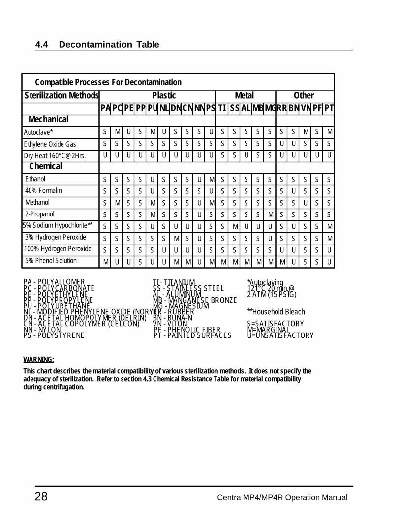
4.4 Decontamination Table
Compatible Processes For Decontamination
Sterilization Methods Plastic Metal OtherPA PC PE PP PU NL CNDN NN PS TI SS AL MGMB RR BN VN PF PT
Mechanical
Chemical
Autoclave*
Ethylene Oxide Gas
Dry Heat 160°C@2Hrs.
Ethanol
40% Formalin
Methanol
2-Propanol
5% Sodium Hypochlorite**
3% Hydrogen Peroxide
100% Hydrogen Peroxide
5% Phenol Solution
S M U S M U S S S U
S S S S S S S S S S
U U U U U U U U U U
S S S S S
S S S S S
S S
S
S SU
S S M S M
U U S S S
U U U U U
S S S S S S S S S SS S S S U S S S U M
S S S S U S S S S U S S S S S S U S S S
S M S S M S S S U M S S S S S S S U S S
S S S S M S S S U S S S S S M S S S S S
S S S S U S U U U S S M U U U S U S S M
S S S S S S M S U S S S S S U S S S S M
S S S S S U U U U S S S S S S U U S S U
M U U U U M M U M M M M M M M U S S U
PA - POLYALLOMERPC - POLYCARBONATEPE - POLYETHYLENEPP - POLYPROPYLENEPU - POLYURETHANENL - MODIFIED PHENYLENE OXIDE (NORYL)DN - ACETAL HOMOPOLYMER (DELRIN)CN - ACETAL COPOLYMER (CELCON)NN - NYLONPS - POLYSTYRENE
TI - TITANIUMSS - STAINLESS STEELAL - ALUMINUMMB - MANGANESE BRONZEMG - MAGNESIUMRR - RUBBERBN - BUNA-NVN - VITON
PT - PAINTED SURFACESPF - PHENOLIC FIBER
*Autoclaving121°C 20 min.@2 ATM (15 PSIG)
**Household Bleach
S=SATISFACTORYM=MARGINALU=UNSATISFACTORY
WARNING:
This chart describes the material compatibility of various sterilization methods. It does not specify the adequacy of sterilization. Refer to section 4.3 Chemical Resistance Table for material compatibility during centrifugation.
Centra-MP4/MP4R Operation Manual 29
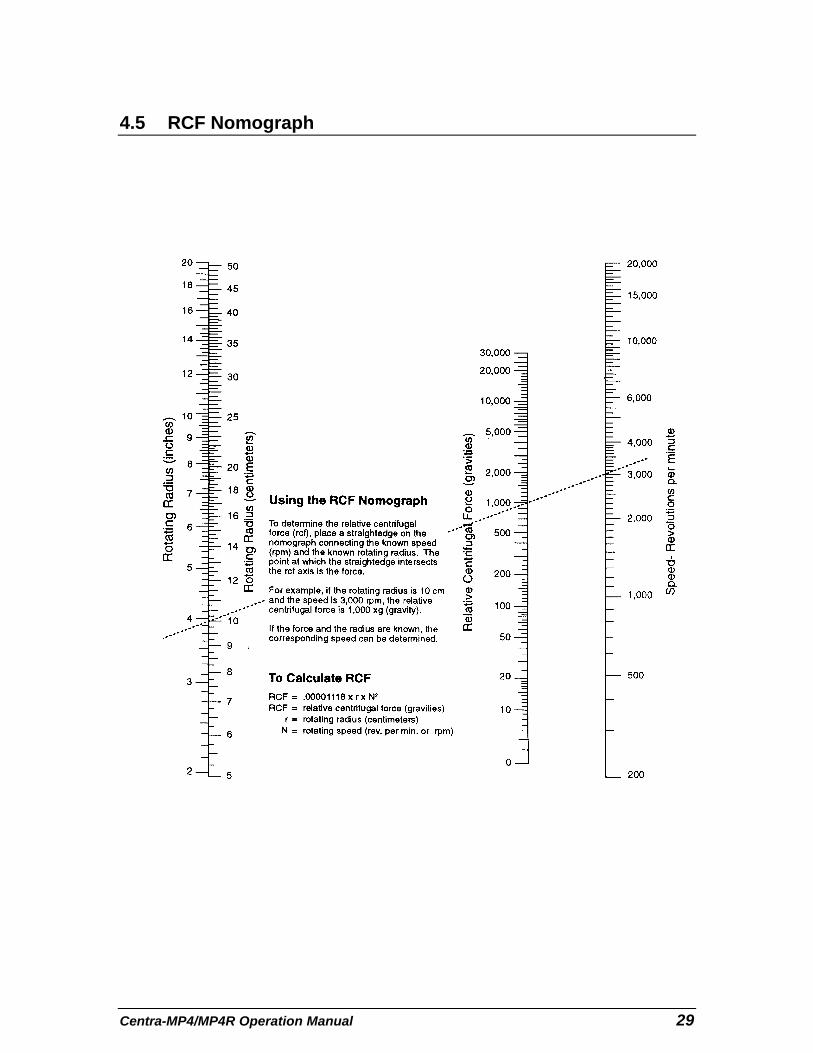
4.5 RCF Nomograph
Centra MP4/MP4R Operation Manual30
5 MAINTENANCE
5.1 Cleaning
Keep your centrifuge clean to ensure good operation and to extend its life.Clean the entire sample chamber, rotor, and lid at the end of each workday,and also right after any spill.
To clean the sample chamber, use a damp sponge, warm water, and a mildliquid detergent suitable for washing dishes by hand, such as Ivory® liquid.Do not use caustic detergents or detergents that contain chlorine ions, sincethese attack metals. Remove stubborn stains with a plastic scrub pad. Donot use steel wool, wire brushes, abrasives, or sandpaper, since they createcorrosion sites. Never pour water directly into the sample chamber. Scrubthe rotor’s tube cavities with a stiff test-tube brush that has end bristles and anon-metallic tip. After cleaning any part, dry it properly, preferably using aclean, absorbent towel.
If glass breakage occurs, remove all broken pieces immediately. Glassparticles, if present in the chamber, will be ground into a fine grey dust duringcentrifugation. If glass breakage recurs it is recommended that all adaptersand cushions be replaced. Particles of broken glass become imbedded inthe plastic or rubber accessories. These particles can come in contact withnew glass tubes, creating a pressure point which may result in recurringglass breakage.
Cleaning swinging bucket rotors is necessary to ensure that the bucketscan pivot freely. Periodically manipulate each bucket; if you feel resistanceor hear squeaking, lubricate all buckets with Bonded Lubricant Coating(BLC), IEC Part No. 7133. Use the following cleaning and lubricationprocedure:
1. Wipe the old lubricant from all rotor pins and buckets with a soft, clean,lint-free cloth saturated with solvent such as trichloroethylene.
2. Clean the rotor and buckets as described above. The cleaning step isimportant because BLC only adheres to a clean surface. If you areunable to remove foreign matter in this way, contact an authorized IECService Representative.
3. Shake the bottle of BLC vigorously until all the gray sediment at thebottom of the bottle is dispersed.
31Centra MP4/MP4R Operation Manual
4. Use the brush applicator cap to apply a light coating of BLC to the bucketslots only. Do not lubricate the pins. Lubricant will move around the pinsduring a spin.
5. Give the BLC 1 to 2 minutes to dry. Buff the bucket slots vigorously witha soft, clean, lint-free cloth. Continue until no more BLC rubs off onto thecloth. The surface will be a shiny, light gray.
Corrosion IEC manufactures and finishes rotors and structural accessories to givemaximum resistance to corrosion. However, maximum equipment liferequires that you continually inspect the rotor cavities for corrosion,especially after using chloride ion solutions, such as sodium chloride (saline),and sodium hypochlorite (household bleach). These solutions attack mostmetals. Clean the rotor, rotor chamber, and accessories (particularly thesample compartments and bucket cups) thoroughly after each such use.Inspect all surfaces under bright light for corrosion; small crevices will growdeeper and cause failure.
Replace the shaft, metal locking screw, rotor or accessories if they becomebadly corroded, cracked deformed or gouged.
If you see any corrosion, remove it immediately as follows:
1. Follow the cleaning procedure at the start of this section. Soak the partin the mild hand-dishwashing detergent. Scrub the part thoroughly with astiff test-tube brush having end bristles and a non-metallic tip.
2. Soak the part again in clear warm water for at least an hour.
3. Rinse the part thoroughly in warm water first, then in distilled water.
4. Dry the part thoroughly with a clean, absorbent cloth.
5. If this procedure does not remove the corrosion, discontinue use of thepart.
Storage Store parts on a soft surface to avoid damaging finished surfaces. Rotorsand other parts should be clean and dry for storage. Store them open to theatmosphere, not in a plastic bag, so that any residual moisture will evaporate.The parts should face downward to avoid retaining moisture in the cavities.
Decontamination Decontamination is called for if tube breakage occurs and infectious,pathogenic, or radioactive material is released into the unit. Some rotorstotally contain the sample tubes. In this case, spillage is usually confined tothe rotor. If so, it may be sufficient to decontaminate the rotor. TheDecontamination Table lists the sensitivity of various materials to commonsterilization procedures. When using a 1-to-10 dilution of household bleach(sodium hypochlorite) to decontaminate metal rotors or accessories, followdecontamination by the corrosion cleaning procedure given earlier, sincechloride ions attack most metals.
Centra MP4/MP4R Operation Manual32
Always decontaminate for the minimum recommended time. If you observecorrosion, remove it as described earlier, discontinue use of the method, anduse an alternate decontamination procedure.
Sterilization of polypropylene rotors can be done by autoclaving. Removeany sample tubes before autoclaving, unless they are completely full ofsample, or remove caps, stoppers, and other tube closures, beforeautoclaving to keep the tubes from collapsing under pressure. Autoclave the
rotor and accessories at 121° C @ 15 psig for 20 minutes. Do not stackpolypropylene rotors during autoclaving. After the rotor is cool to the touch,do a normal cleaning operation as described above.
Repeated autoclaving will seriously degrade the performance ofpolycarbonate materials.
5.2 Cover Interlock Bypass
If power fails, the cover remains locked. If you need to remove samples fromthe unit before power is restored, use the cover interlock bypass after therotor has come to a stop.
Unplug the centrifuge. Locate a hidden plug just below the front panel. Usea screwdriver to remove this plug. Pull the attached cord to release the coverinterlock. Reassemble the plug in the hole.
Do not perform this operation routinely. The centrifuge’s cover interlockprovides operator safety and allows the cover to be opened promptlywhenever rotation has stopped.
5.3 Calibration
The built-in, independent digital tachometer in your centrifuge is calibrated byIEC according to standards that are traceable to the U.S. National Institute ofStandards and Technology (NIST). The built-in tachometer uses crystalstandards that do not drift. Therefore, IEC recommends verifying the RPMindicator once every 24 months. This can be done easily using an opticaltachometer through the clear plastic viewport in the lid. If this measurementindicates instrument tachometer failure, please notify IEC Technical Service.
33Centra MP4/MP4R Operation Manual
5.4 Brush Replacement
Brush replacement is required when brush length is 1/4 inch or less, or whenthe front panel displays “bruSh” at the end of a spin. The "bruSh" warningoccurs every 700 hours of actual spin time. A set of replacement brushes isincluded with the centrifuge.
Open the cover and unplug the centrifuge. Unscrew the locking screw andremove the rotor and all accessories. Locate the rubber motor boot at thebottom of the rotor chamber. It is attached to the motor by a ring with 4screws, and is fitted to the rotor chamber. Gently push the boot toward themotor shaft to seperate it from the guard bowl. Locate and unscrew the twobrush holder caps (protruding from both sides of the motor). Take care notto drop the brush caps into the motor well! Inside each cap is a brushassembly, consisting of a rectangular carbon brush, a spring, and a copperwire inside the spring. Remove and discard from both sides of the motor theentire assembly inside each cap. Replace them with the spares. Thebrush’s rectangular shape keeps it from being inserted improperly. Screw thecaps back in. Reinstall the motor boot assembly. Plug the centrifuge backinto the power outlet.
Order a new set of brushes; IEC Part No. 50433.
The “bruSh” warning indication on the front panel must now be reset. To doso, follow this procedure:
1. Press the SPECIAL FUNCTIONS button located behind the “C” in IEC.The RPM display now shows one of a set of Special Functions. Thismenu is primarily used by service personnel.
2. Press either RPM arrow key until the RPM display shows “bruSh”. TheMINUTES display now shows the hours of brush life. At brushreplacement, this number is 700 or over.
3. Press the File key to set the brush life back to 0, reflecting the installationof new brushes.
4. Press the SPECIAL FUNCTIONS button again to return the unit tonormal operation.

Centra MP4/MP4R Operation Manual34
5.5 Table of Spare Parts
48407 Rotor Locking Screw9946 Fuse 6.3 A, 200/240 V50058 Fuse 16 A, 100/120 V50433 Brushes, One Pair50431 Brush Caps, One Pair7133 BLC (Bonded Lubricant Coating)
5.6 Warranty
IEC wants you to be satisfied with the quality of your Centra-MP4R orCentra-MP4 centrifuge. We warrantee your IEC centrifuge for one year andIEC rotors for seven years. We will repair or replace any of these productsthat fails, within this period from the date of its delivery, due to defects inmaterial and workmanship, and we will ship you the repaired product or itsreplacement at our expense. You must use IEC approved accessories andgenuine IEC spare parts. This warranty does not apply to any instrumentthat has been abused or repaired without authorization.
THE FOREGOING OBLIGATIONS ARE IN LIEU OF ALL OTHEROBLIGATIONS AND LIABILITIES INCLUDING NEGLIGENCE, AND ALLWARRANTIES, OF MERCHANTABILITY OR OTHERWISE, EXPRESSEDOR IMPLIED IN FACT OR BY LAW. THE FOREGOING STATES OURENTIRE AND EXCLUSIVE LIABILITY, AND BUYER’S EXCLUSIVEREMEDY, FOR ANY CLAIM OR DAMAGES IN CONNECTION WITH THESALE OR FURNISHING OF GOODS OR PARTS, THEIR DESIGN,SUITABILITY FOR USE, INSTALLATION, OR OPERATION. IEC WILL INNO EVENT BE LIABLE FOR ANY SPECIAL OR CONSEQUENTIALDAMAGES WHATSOEVER, AND OUR LIABILITY UNDER NOCIRCUMSTANCES WILL EXCEED THE PURCHASE PRICE FOR THEGOODS FOR WHICH LIABILITY IS CLAIMED.
35Centra MP4/MP4R Operation Manual
5.7 Condition of Returned Equipment
Before returning equipment to IEC, you must contact IEC or your dealer andreceive a return goods authorization (RGA). All returned units must bedecontaminated, free of radioactivity, and free of hazardous andinfectious materials. The RGA paperwork includes a Certificate ofDecontamination for you to sign indicating that you have performed thesesteps. IEC will not accept the shipment until this signed certificate isreceived.
You must prepay transportation to the service depot.
5.8 Fuses Not Replaceable By The Operator
Four internal fuses are not replaceable by the operator. Thesefuses should only be replaced by qualified service personnel.
F1 2.5A T 250VF2 6.3A T 250VF3 2.0A T 125VF4 1.0A T 125V
Centra MP4/MP4R Operation Manual36
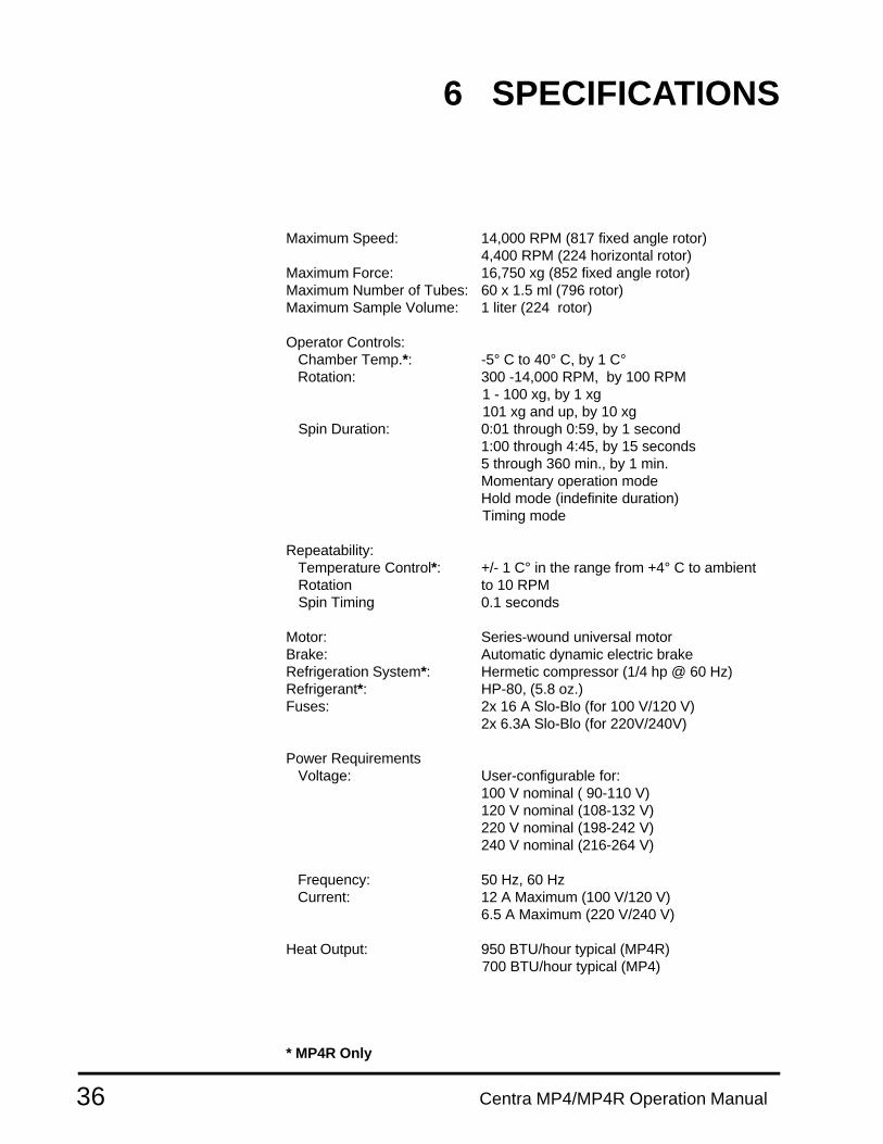
6 SPECIFICATIONS
Maximum Speed: 14,000 RPM (817 fixed angle rotor)4,400 RPM (224 horizontal rotor)
Maximum Force: 16,750 xg (852 fixed angle rotor)Maximum Number of Tubes: 60 x 1.5 ml (796 rotor)Maximum Sample Volume: 1 liter (224 rotor)
Operator Controls: Chamber Temp.*: -5° C to 40° C, by 1 C° Rotation: 300 -14,000 RPM, by 100 RPM
1 - 100 xg, by 1 xg 101 xg and up, by 10 xg
Spin Duration: 0:01 through 0:59, by 1 second1:00 through 4:45, by 15 seconds5 through 360 min., by 1 min.Momentary operation modeHold mode (indefinite duration)
Timing mode
Repeatability: Temperature Control*: +/- 1 C° in the range from +4° C to ambient Rotation to 10 RPM Spin Timing 0.1 seconds
Motor: Series-wound universal motorBrake: Automatic dynamic electric brakeRefrigeration System*: Hermetic compressor (1/4 hp @ 60 Hz)Refrigerant*: HP-80, (5.8 oz.)Fuses: 2x 16 A Slo-Blo (for 100 V/120 V)
2x 6.3A Slo-Blo (for 220V/240V)
Power Requirements Voltage: User-configurable for:
100 V nominal ( 90-110 V)120 V nominal (108-132 V)220 V nominal (198-242 V)240 V nominal (216-264 V)
Frequency: 50 Hz, 60 Hz Current: 12 A Maximum (100 V/120 V)
6.5 A Maximum (220 V/240 V)
Heat Output: 950 BTU/hour typical (MP4R) 700 BTU/hour typical (MP4)
* MP4R Only
37Centra MP4/MP4R Operation Manual
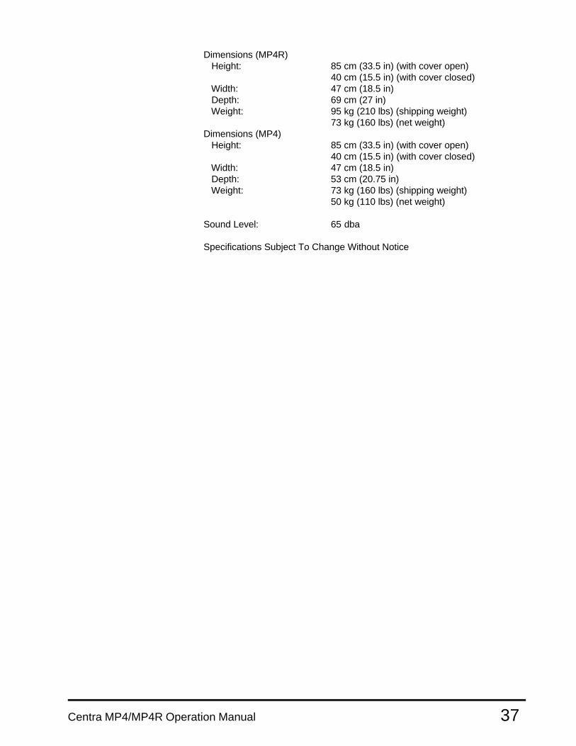
Dimensions (MP4R) Height: 85 cm (33.5 in) (with cover open)
40 cm (15.5 in) (with cover closed) Width: 47 cm (18.5 in) Depth: 69 cm (27 in) Weight: 95 kg (210 lbs) (shipping weight)
73 kg (160 lbs) (net weight)Dimensions (MP4) Height: 85 cm (33.5 in) (with cover open)
40 cm (15.5 in) (with cover closed) Width: 47 cm (18.5 in) Depth: 53 cm (20.75 in) Weight: 73 kg (160 lbs) (shipping weight)
50 kg (110 lbs) (net weight)
Sound Level: 65 dba
Specifications Subject To Change Without Notice