operation of wind energy conversion systems with doubly...
TRANSCRIPT
RUHR-UNIVERSITY BOCHUM
Operation of Wind Energy Conversion Systems withDoubly-Fed Induction Generators During Asymmetrical
Voltage Dips
M.Eng. Pavlos TourouProf. Dr.-Ing. Constantinos Sourkounis
Ruhr-University Bochum, Germany
1111
2nd International Conference onPower Options for the Eastern Mediterranean Region
7-8 October 2013, Nicosia, Cyprus
Contents
2222
! Introduction
! Voltage dips in the case of faults in the electrical grid
! Wind farm connection and voltage dip propagation
! Doubly-Fed Induction Generator (DFIG)
! Analysis of DFIG during asymmetrical voltage dips
! Control system
! Results with proposed control system
! Summary
! Wind energy converters (WECs) = proven & mature technology< In 2011 WECs provided 3.5% of the global electricity demand < expected to rise to 16% by 2030 under a moderate scenario (GWEC 2012)
! WECs and wind farms must:< have advanced operating behaviour much like conventional plants< fulfil stricter grid codes requirements
! Low Voltage Ride Through (LVRT) < WECs must remain in operation in the case of short-term symmetrical and
asymmetrical grid faults< Must support the grid voltage recovery by supplying reactive current to grid
! WECs with doubly-fed induction generators (DFIG), < currently occupying the largest share in the wind energy market, < particularly sensitive to grid disturbances
! Behaviour of the DFIG during assymetrical faults must be studied
! Adequate control systems must be developed
Introduction
3333
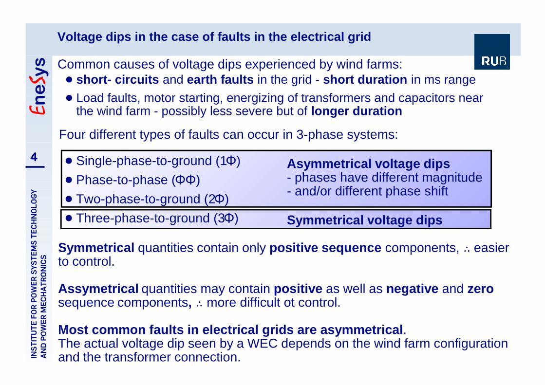
! short- circuits and earth faults in the grid - short duration in ms range
! Load faults, motor starting, energizing of transformers and capacitors nearthe wind farm - possibly less severe but of longer duration
Voltage dips in the case of faults in the electrical grid
4444
Common causes of voltage dips experienced by wind farms:
Four different types of faults can occur in 3-phase systems:
! Single-phase-to-ground (1Φ)
! Phase-to-phase (ΦΦ)
! Two-phase-to-ground (2Φ)
! Three-phase-to-ground (3Φ) Symmetrical voltage dips
Asymmetrical voltage dips- phases have different magnitude- and/or different phase shift
Symmetrical quantities contain only positive sequence components, ˆ̂̂̂ easierto control.
Assymetrical quantities may contain positive as well as negative and zerosequence components, ˆ̂̂̂ more difficult ot control.
Most common faults in electrical grids are asymmetrical.The actual voltage dip seen by a WEC depends on the wind farm configurationand the transformer connection.
V VZ
Z ZPCC g
f
g f
=+
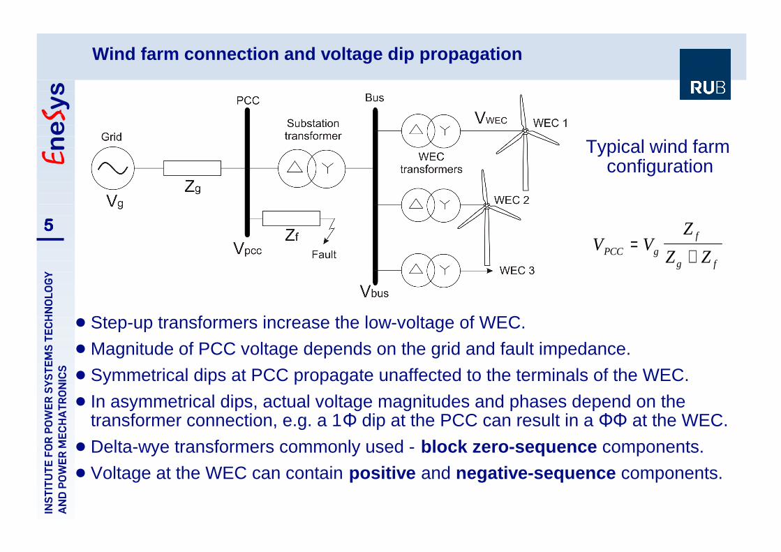
! Step-up transformers increase the low-voltage of WEC.
! Magnitude of PCC voltage depends on the grid and fault impedance.
! Symmetrical dips at PCC propagate unaffected to the terminals of the WEC.
! In asymmetrical dips, actual voltage magnitudes and phases depend on thetransformer connection, e.g. a 1Φ dip at the PCC can result in a ΦΦ at the WEC.
! Delta-wye transformers commonly used - block zero-sequence components.
! Voltage at the WEC can contain positive and negative-sequence components.
Wind farm connection and voltage dip propagation
5555
Typical wind farm configuration

! Most widely used type of generator for wind energy applications - occupiesabout 50% of the market.
! Attractive due to its partially-rated power converters that result in lowercosts and higher efficiency.
! But partially-rated power converters also mean limited control possibilitiesin the case of abnormal conditions such as severe grid faults.
! At extreme voltage dips, rotor overcurrents are redirected to a crowbarresistor in order to protect the sensitive power electronic converters.
Doubly-Fed Induction Generator (DFIG)
6666
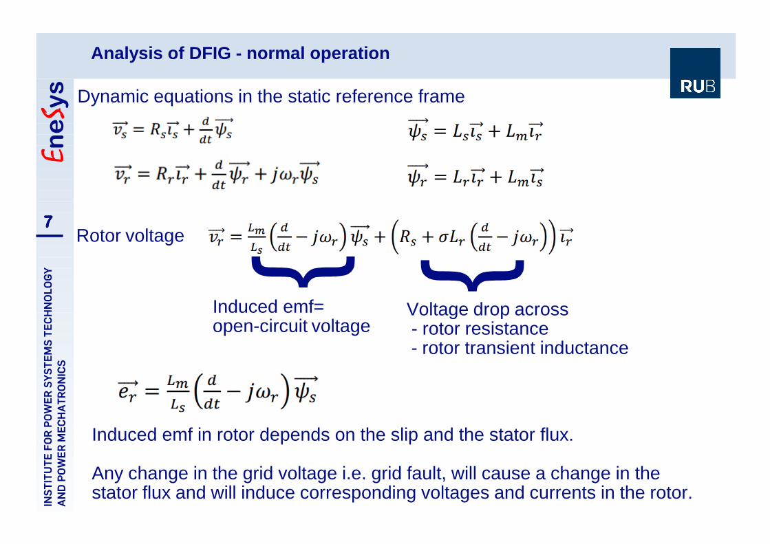
Analysis of DFIG - normal operation
7777Rotor voltage
Dynamic equations in the static reference frame
Induced emf in rotor depends on the slip and the stator flux.
Any change in the grid voltage i.e. grid fault, will cause a change in thestator flux and will induce corresponding voltages and currents in the rotor.
Induced emf=open-circuit voltage
Voltage drop across - rotor resistance - rotor transient inductance

Analysis of DFIG - during asymmetrical voltage dips (1)
8888
3 Stator flux components during asymmetrical voltage dips: positive-sequence flux, negative- sequence flux and a transient flux
Each stator flux component induces a corresponding component in the rotorvoltage
! Negative-sequence rotor voltage is proportional to negative-sequence statorvoltage V2 and to (slip-2) þ can create large negative-sequence currents
! Control system must be able to regulate negative-sequence currents as well

! Asymmetrical stator currents cause uneven heating in the stator windings ifthe fault is maintained for a long period.
! Oscillations in the active and reactive power in the stator and rotor whichare superimposed on the average active and reactive power.
! High torque oscillations at double the grid frequency.
! 100 Hz oscillations in the DC-link voltage.
Analysis of DFIG - during asymmetrical voltage dips (2)
9999
Effects of asymmetrical votage dips on the DFIG:
Active and reactive powers Electromagnetic torque
Interaction of negative and positivesequence voltages and currents in thestator and rotor þ oscillations in theactive and reactive power as well as inthe torque
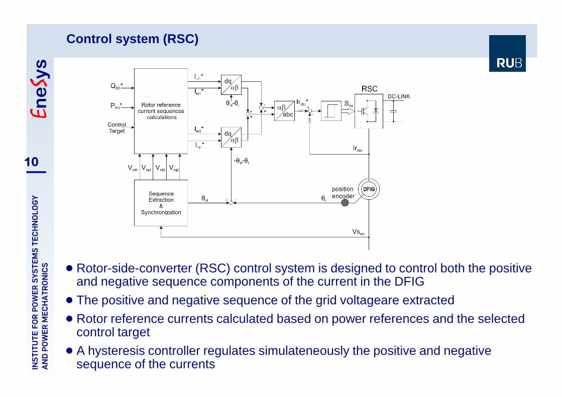
Control system (RSC)
10101010
! Rotor-side-converter (RSC) control system is designed to control both the positiveand negative sequence components of the current in the DFIG
! The positive and negative sequence of the grid voltageare extracted
! Rotor reference currents calculated based on power references and the selectedcontrol target
! A hysteresis controller regulates simulateneously the positive and negativesequence of the currents
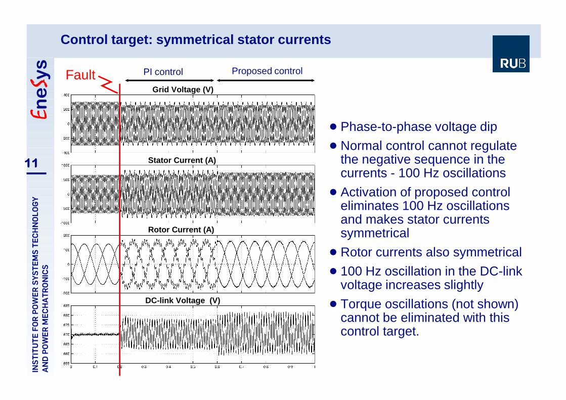
! Phase-to-phase voltage dip
! Normal control cannot regulatethe negative sequence in thecurrents - 100 Hz oscillations
! Activation of proposed controleliminates 100 Hz oscillationsand makes stator currentssymmetrical
! Rotor currents also symmetrical
! 100 Hz oscillation in the DC-linkvoltage increases slightly
! Torque oscillations (not shown)cannot be eliminated with thiscontrol target.
Control target: symmetrical stator currents
11111111
PI control Proposed control
Grid Voltage (V)
Stator Current (A)
Rotor Current (A)
DC-link Voltage (V)
Fault
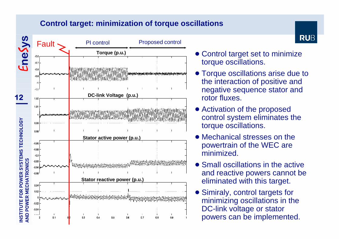
! Control target set to minimizetorque oscillations.
! Torque oscillations arise due tothe interaction of positive andnegative sequence stator androtor fluxes.
! Activation of the proposedcontrol system eliminates thetorque oscillations.
! Mechanical stresses on thepowertrain of the WEC areminimized.
! Small oscillations in the activeand reactive powers cannot beeliminated with this target.
! Simiraly, control targets forminimizing oscillations in theDC-link voltage or statorpowers can be implemented.
Control target: minimization of torque oscillations
12121212
PI control Proposed control
Torque (p.u.)
Stator active power (p.u.)
DC-link Voltage (p.u.)
Fault
Stator reactive power (p.u.)
! Asymmetrical voltage dips due to grid faults are more common thansymmetrical grid faults.
! Asymmetrical voltage dips in the electrical grid can degrade theperformance of the doubly-fed induction generator due to the direct gridconnection of the stator and the partially-rated power electronic converters.
! Negative sequence in the stator voltage causes double frequencyoscillations in the currents, voltages, torques, powers and DC-link of theDFIG.
! By controlling both the positive and negative sequence currents, differentperformance objectives can be achieved.
! Coordinated control of the RSC and GSC can improve the performancesignificantly.
! The control targets can be achieved as long as the induced emf in therotor is not greater than the maximum voltage that can be imposed by theRSC.
Summary
13131313

14141414
Thank you for your attention!