operator's manual...- check engine oil level - check transmission oil level - check coolant...
TRANSCRIPT
English (Australia)Code No. 3Y206-9971-1
M100GX·M110GXM126GX·M135GX
MODELS
OPERATOR'S MANUAL
M100GX·M110GX·M126GX·M135GX
© KUBOTA Corporation 2012PRINTED IN JAPAN
READ AND SAVE THIS MANUAL
KUBOTA Corporation is ···Since its inception in 1890, KUBOTA Corporation has grown to rank as one of the major firms in Japan.
To achieve this status, the company has through the years diversified the range of its products and services to a remarkable extent. Nineteen plants and 16,000 employees produce over 1,000 different items, large and small.
All these products and all the services which accompany them, however, are unified by one central commitment. KUBOTA makes products which, taken on a national scale, are basic necessities. Products which are indispensable. Products which are intended to help individuals and nations fulfill the potential inherent in their environment. KUBOTA is the Basic Necessities Giant.
This potential includes water supply, food from the soil and from the sea, industrial development, architecture and construction, and transportation.
Thousands of people depend on KUBOTA's know-how, technology, experience and customer service. You too can depend on KUBOTA.
M100GX/M110GX/M126GX/M135GXAQ . L . 1 - 1 . 2 . AK
Abbreviations Definitions
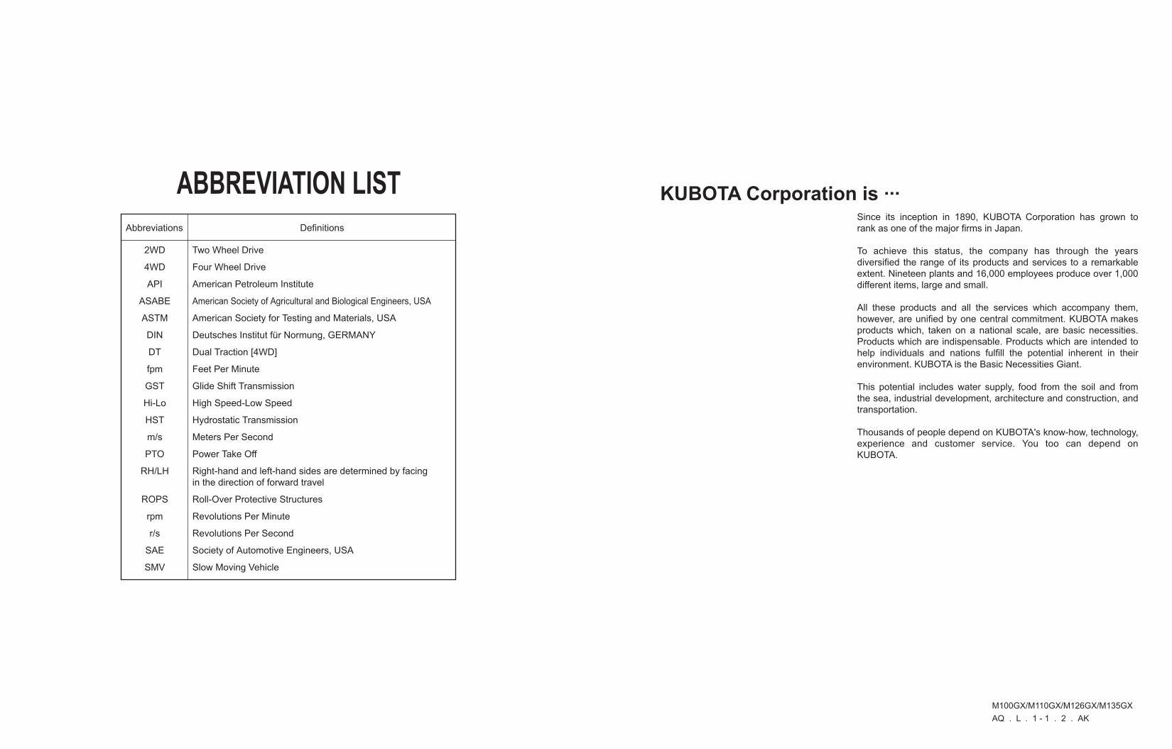
ABBREVIATION LIST
Two Wheel Drive
Four Wheel Drive
American Petroleum Institute
American Society of Agricultural and Biological Engineers, USA
American Society for Testing and Materials, USA
Deutsches Institut für Normung, GERMANY
Dual Traction [4WD]
Feet Per Minute
Glide Shift Transmission
High Speed-Low Speed
Hydrostatic Transmission
Meters Per Second
Power Take Off
Right-hand and left-hand sides are determined by facing in the direction of forward travel
Roll-Over Protective Structures
Revolutions Per Minute
Revolutions Per Second
Society of Automotive Engineers, USA
Slow Moving Vehicle
2WD
4WD
API
ASABE
ASTM
DIN
DT
fpm
GST
Hi-Lo
HST
m/s
PTO
RH/LH
ROPS
rpm
r/s
SAE
SMV

UNIVERSAL SYMBOLSAs a guide to the operation of your tractor, various universal symbols have been utilized on the instruments and controls. The symbols are shown below with an indication of their meaning.
Safety Alert Symbol
Engine Warning
Diesel Fuel
Engine-Rotational Speed
Hourmeter/ElapsedOperating Hours
Engine Coolant-Temperature
Diesel Preheat/GlowPlugs(Low TemperatureStart Aid)
Parking Brake
Engine Oil-Pressure
Turn Signal
Electrical Power-accessories
Engine-Run
Engine-Start
Engine-Stop
Power Take-Off ClutchControl-Off (Disengaged)Position
Power Take-Off ClutchControl-On (Engaged)Position
Bi-Speed turn
Differential Lock, Front
Differential Lock, Rear
Auto-Mode
Position Control-RaisedPosition
Position Control-LoweredPosition
3-Point Lifting / Lowering
Lift Arm Height
Draft Control
Remote Cylinder-Retract
Remote Cylinder-Extend
Remote Cylinder-Float
Hazard Warning Lights
Headlight-Low Beam
Headlight-High Beam
Four-Wheel Drive-On
Fast
Slow
Creep
Windshield Wiper
Windshield WiperIntermittent
Windshield Washer
Audible Warning Device
Lock
Rear Window Defroster
Steering Wheel-Tilt Control
Steering Wheel-Telescope Control
Side Window Defroster
Empty
Full
PTO 540 rpm
PTO 1000 rpm
Engine Intake/CombustionAir-Filter
Battery Charging Condition
Rev-limiter Control
Constant RPM Management
Front Suspension
Regeneration
Auto Regeneration (Switch)
Regeneration (Switch)
Parked Regeneration
Engine RPM Increase
Master System Warning
Beacon Light

FOREWORD
3SAFETY FIRST
IMPORTANT :
NOTE :
3 DANGER :
3 WARNING :
3 CAUTION :
Indicates an imminently hazardous situation which, if not avoided, will result in death or serious injury.
Indicates a potentially hazardous situation which, if not avoided, could result in death or serious injury.
Indicates a potentially hazardous situation which, if not avoided, may result in minor or moderate injury.
Indicates that equipment or property damage could result if instructions are not followed.
Gives helpful information.
You are now the proud owner of a KUBOTA Tractor. This tractor is a product of KUBOTA quality engineering and manufacturing. It is made of fine materials and under a rigid quality control system. It will give you long, satisfactory service. To obtain the best use of your tractor, please read this manual carefully. It will help you become familiar with the operation of the tractor and contains many helpful hints about tractor maintenance. It is KUBOTA's policy to utilize as quickly as possible every advance in our research. The immediate use of new techniques in the manufacture of products may cause some small parts of this manual to be outdated. KUBOTA distributors and dealers will have the most up-to-date information. Please do not hesitate to consult with them.
This symbol, the industry's ''Safety Alert Symbol'', is used throughout this manual and on labels on the machine itself to warn of the possibility of personal injury. Read these instructions carefully. It is essential that you read the instructions and safety regulations before you attempt to assemble or use this unit.
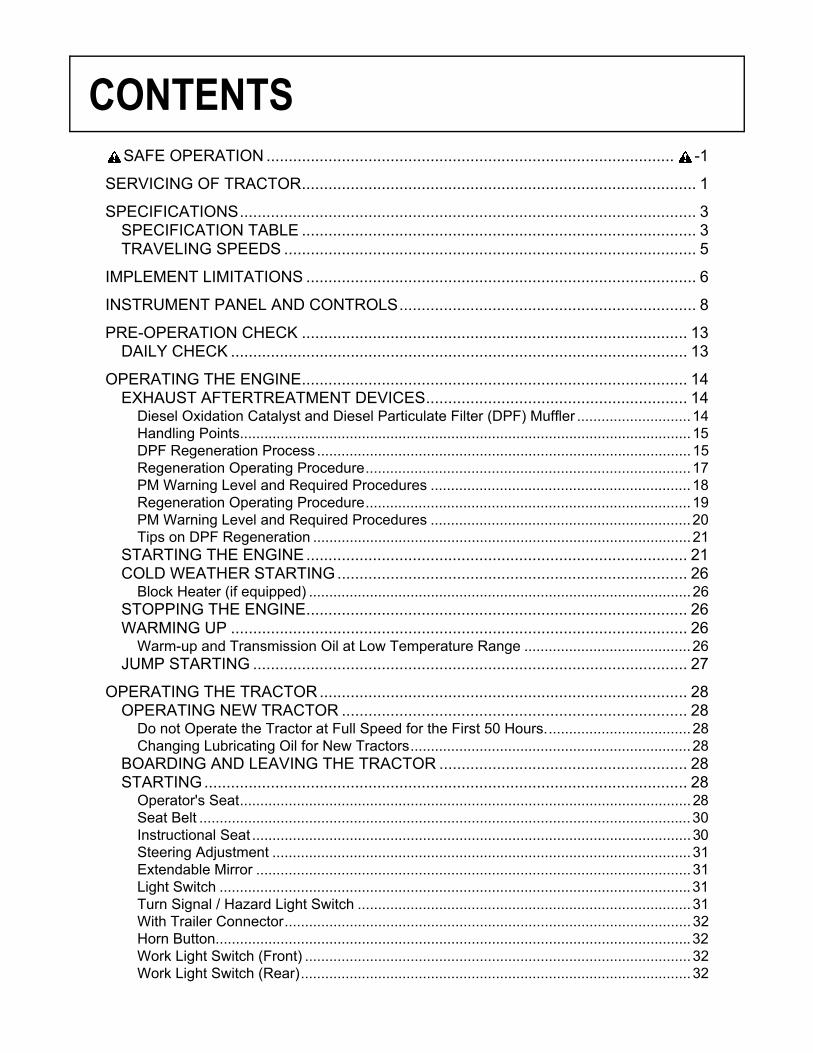
CONTENTS
SAFE OPERATION ............................................................................................ -1SERVICING OF TRACTOR......................................................................................... 1
SPECIFICATIONS....................................................................................................... 3SPECIFICATION TABLE ......................................................................................... 3TRAVELING SPEEDS ............................................................................................. 5
IMPLEMENT LIMITATIONS ........................................................................................ 6
INSTRUMENT PANEL AND CONTROLS................................................................... 8
PRE-OPERATION CHECK ....................................................................................... 13DAILY CHECK ....................................................................................................... 13
OPERATING THE ENGINE....................................................................................... 14EXHAUST AFTERTREATMENT DEVICES........................................................... 14
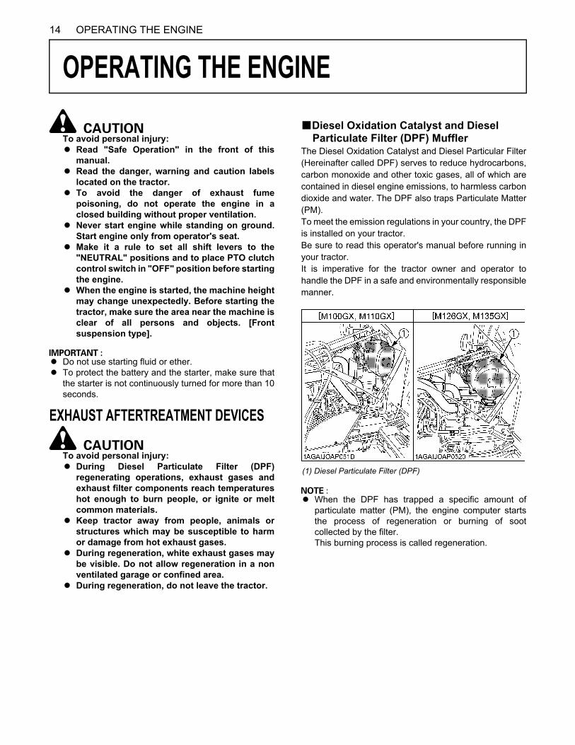
Diesel Oxidation Catalyst and Diesel Particulate Filter (DPF) Muffler ............................14Handling Points...............................................................................................................15DPF Regeneration Process............................................................................................15Regeneration Operating Procedure................................................................................17PM Warning Level and Required Procedures ................................................................18Regeneration Operating Procedure................................................................................19PM Warning Level and Required Procedures ................................................................20Tips on DPF Regeneration .............................................................................................21
STARTING THE ENGINE...................................................................................... 21COLD WEATHER STARTING............................................................................... 26
Block Heater (if equipped) ..............................................................................................26STOPPING THE ENGINE...................................................................................... 26WARMING UP ....................................................................................................... 26
Warm-up and Transmission Oil at Low Temperature Range .........................................26JUMP STARTING .................................................................................................. 27
OPERATING THE TRACTOR................................................................................... 28OPERATING NEW TRACTOR .............................................................................. 28
Do not Operate the Tractor at Full Speed for the First 50 Hours....................................28Changing Lubricating Oil for New Tractors.....................................................................28
BOARDING AND LEAVING THE TRACTOR ........................................................ 28STARTING............................................................................................................. 28
Operator's Seat...............................................................................................................28Seat Belt .........................................................................................................................30Instructional Seat ............................................................................................................30Steering Adjustment .......................................................................................................31Extendable Mirror ...........................................................................................................31Light Switch ....................................................................................................................31Turn Signal / Hazard Light Switch ..................................................................................31With Trailer Connector....................................................................................................32Horn Button.....................................................................................................................32Work Light Switch (Front) ...............................................................................................32Work Light Switch (Rear)................................................................................................32
CONTENTS
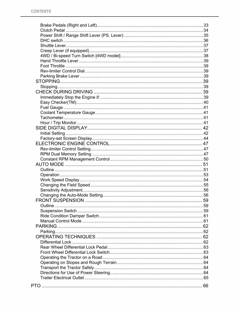
Brake Pedals (Right and Left).........................................................................................33Clutch Pedal ...................................................................................................................34Power Shift / Range Shift Lever (PS. Lever) ..................................................................35DHC switch .....................................................................................................................36Shuttle Lever...................................................................................................................37Creep Lever (if equipped) ...............................................................................................374WD / Bi-speed Turn Switch [4WD model].....................................................................38Hand Throttle Lever ........................................................................................................39Foot Throttle ...................................................................................................................39Rev-limiter Control Dial...................................................................................................39Parking Brake Lever .......................................................................................................39
STOPPING............................................................................................................. 39Stopping..........................................................................................................................39
CHECK DURING DRIVING ................................................................................... 39Immediately Stop the Engine if: ......................................................................................39Easy Checker(TM)..........................................................................................................40Fuel Gauge.....................................................................................................................41Coolant Temperature Gauge..........................................................................................41Tachometer.....................................................................................................................41Hour / Trip Monitor..........................................................................................................41
SIDE DIGITAL DISPLAY........................................................................................ 42Initial Setting ...................................................................................................................42Factory-set Screen Display.............................................................................................44
ELECTRONIC ENGINE CONTROL....................................................................... 47Rev-limiter Control Setting..............................................................................................47RPM Dual Memory Setting .............................................................................................47Constant RPM Management Control..............................................................................50
AUTO MODE ......................................................................................................... 51Outline ............................................................................................................................51Operation........................................................................................................................53Work Speed Display .......................................................................................................54Changing the Field Speed ..............................................................................................55Sensitivity Adjustment.....................................................................................................56Changing the Auto-Mode Setting....................................................................................56
FRONT SUSPENSION .......................................................................................... 59Outline ............................................................................................................................59Suspension Switch .........................................................................................................59Ride Condition Damper Switch.......................................................................................61Manual Control Mode .....................................................................................................61
PARKING............................................................................................................... 62Parking............................................................................................................................62
OPERATING TECHNIQUES ................................................................................. 62Differential Lock ..............................................................................................................62Rear Wheel Differential Lock Pedal................................................................................63Front Wheel Differential Lock Switch..............................................................................63Operating the Tractor on a Road....................................................................................64Operating on Slopes and Rough Terrain ........................................................................64Transport the Tractor Safely ...........................................................................................64Directions for Use of Power Steering..............................................................................64Trailer Electrical Outlet ...................................................................................................65
PTO ........................................................................................................................... 66
CONTENTS
PTO OPERATION.................................................................................................. 66PTO Clutch Control Switch .............................................................................................66PTO Gear Shift Lever .....................................................................................................67PTO Gear Shift Lever .....................................................................................................68PTO Shaft Cover and Shaft Cap ....................................................................................68
THREE-POINT HITCH & DRAWBAR........................................................................ 693-POINT HITCH..................................................................................................... 70
Selecting the holes of Lower Links .................................................................................70Adjusting Lateral Float ....................................................................................................70Selecting the Top Link Mounting Holes ..........................................................................70Drawbar ..........................................................................................................................70Remote Hitch UP / DOWN Switch ..................................................................................71Lifting Rod (Left) .............................................................................................................71Lifting Rod (Right)...........................................................................................................71Top Link..........................................................................................................................72Telescopic Stabilizers .....................................................................................................72Quick Hitch (Hook type)..................................................................................................72
DRAWBAR............................................................................................................. 74Adjusting Drawbar Length ..............................................................................................74Swing Drawbar ...............................................................................................................74
HYDRAULIC UNIT..................................................................................................... 753-POINT HITCH CONTROL SYSTEM................................................................... 75
Terminology ....................................................................................................................75Mode Selector Switch .....................................................................................................76Position Control Mode ....................................................................................................76Mixed Draft Control Mode...............................................................................................77Float Control ...................................................................................................................77Bottom Limit Control Dial ................................................................................................78Lift Arm Top Limit Adjustment Dial .................................................................................783-Point Hitch Lowering Speed Adjustment Dial ..............................................................783-Point Hitch Lowering Lock Lever .................................................................................783-P. Quick Raise / Lower Switch ....................................................................................793-Point Hitch's Position Lock ..........................................................................................80
REMOTE HYDRAULIC CONTROL SYSTEM........................................................ 80Remote Control Valve.....................................................................................................80Remote Control Valve Lever...........................................................................................80Remote Control Valve Coupler Connecting and Disconnecting .....................................81Adjusting the flow rate ....................................................................................................81Remote Couplers Spillage Collector...............................................................................82Hydraulic Control Unit Use Reference Chart ..................................................................83
TIRES, WHEELS AND BALLAST.............................................................................. 84TIRES..................................................................................................................... 84
Inflation Pressure............................................................................................................84Dual Tires .......................................................................................................................84
WHEEL ADJUSTMENT ......................................................................................... 85Front Wheels (with four wheel drive) ..............................................................................85Adjusting Front Wheel Turning Stopper Bolt ..................................................................86Rear Wheels ...................................................................................................................87
BALLAST ............................................................................................................... 88Front Ballast....................................................................................................................88
CONTENTS
Rear Ballast ....................................................................................................................89
CAB OPERATION ..................................................................................................... 90DOOR AND WINDOW........................................................................................... 90
Locking and Unlocking the Door.....................................................................................90Opening the Door ...........................................................................................................90Rear Window ..................................................................................................................90Sun Roof.........................................................................................................................91Emergency Exit...............................................................................................................91
DOME LIGHT......................................................................................................... 91Dome Light .....................................................................................................................91
WIPER ................................................................................................................... 91Front Wiper / Washer Switch ..........................................................................................91Rear Wiper / Washer Switch...........................................................................................92Using the Wipers in Cold Season...................................................................................92
AIR CONDITIONER............................................................................................... 92Airflow.............................................................................................................................92Air Control Vent ..............................................................................................................93Control Panel ..................................................................................................................93Operation........................................................................................................................94
INSTALLING THE IMPLEMENT CONTROL BOX................................................. 96ELECTRICAL OUTLET.......................................................................................... 96
Electrical Outlet...............................................................................................................96BEACON LIGHT .................................................................................................... 97
Beacon Light Switch .......................................................................................................97
MAINTENANCE......................................................................................................... 98SERVICE INTERVALS .......................................................................................... 98LUBRICANTS, FUEL AND COOLANT ................................................................ 102
PERIODIC SERVICE............................................................................................... 104HOW TO OPEN THE HOOD ............................................................................... 104
Hood .............................................................................................................................104Side Cover ....................................................................................................................104
DAILY CHECK ..................................................................................................... 104Walk Around Inspection................................................................................................105Checking and Refueling................................................................................................105Checking Water Separator ...........................................................................................105Checking Engine Oil Level............................................................................................106Checking Transmission Fluid Level ..............................................................................106Checking Coolant Level................................................................................................106Cleaning Evacuator Valve ............................................................................................107Cleaning Grill, Radiator and Screen .............................................................................107Checking DPF Muffler...................................................................................................109Checking Brake Pedal ..................................................................................................109Checking Gauges, Meter and Easy Checker(TM) ........................................................109Checking Head Light, Turn Signal / Hazard Light etc...................................................109Checking Seat Belt .......................................................................................................109Checking Movable Parts...............................................................................................109
EVERY 50 HOURS.............................................................................................. 110Checking Engine Start System.....................................................................................110Checking Wheel Bolt Torque........................................................................................111Checking Tie-rod Dust Cover .......................................................................................111
CONTENTS
EVERY 100 HOURS............................................................................................ 111Lubricating Grease Fittings...........................................................................................111Cleaning Air Cleaner Primary Element .........................................................................113Adjusting Fan Belt Tension...........................................................................................114Checking Fuel Line.......................................................................................................114Adjusting Brake Pedal ..................................................................................................115Adjusting Parking Brake Lever .....................................................................................115Checking Battery Condition ..........................................................................................116
EVERY 200 HOURS............................................................................................ 117Checking Radiator Hose and Clamp ............................................................................117Checking Oil Cooler Line..............................................................................................119Checking Intake Air Line...............................................................................................119Checking Power Steering Line .....................................................................................119Adjusting Toe-in............................................................................................................120Draining Fuel Tank Water.............................................................................................120Cleaning Inner Air Filter ................................................................................................121Cleaning Fresh Air Filter ...............................................................................................121Adjusting Air-Conditioner Belt Tension .........................................................................122
EVERY 300 HOURS............................................................................................ 122Replacing Hydraulic Oil Filter .......................................................................................122
EVERY 400 HOURS............................................................................................ 123Changing Engine Oil.....................................................................................................123Replacing Engine Oil Filter ...........................................................................................124Checking Fan / Air-conditioner Belt Tension ................................................................124Cleaning Pre-Fuel Filter................................................................................................126Replacing Fuel Filter.....................................................................................................126Cleaning Water Separator ............................................................................................126Cleaning Fuel Solenoid Pump Element ........................................................................127
EVERY 600 HOURS............................................................................................ 128Changing Transmission Fluid .......................................................................................128Changing Front Differential Case Oil ............................................................................129Changing Front Axle Gear Case Oil .............................................................................129Adjusting Front Axle Pivot.............................................................................................130Adjusting King-pin Pivot................................................................................................130
EVERY 800 HOURS............................................................................................ 130Replacing Fuel Filter.....................................................................................................130Adjusting Engine Valve Clearance ...............................................................................130
EVERY 1500 HOURS.......................................................................................... 130Cleaning Fuel Injector Nozzle Tip.................................................................................130Checking and Cleaning EGR Cooler ............................................................................130Checking Accumulator..................................................................................................130
EVERY 3000 HOURS.......................................................................................... 130Checking Turbocharger ................................................................................................130Checking Supply Pump ................................................................................................130Checking Intake Air Heater...........................................................................................131Checking and Cleaning EGR System...........................................................................131Cleaning DPF Muffler ...................................................................................................131
EVERY 1 YEAR ................................................................................................... 131Replacing Air Cleaner Primary Element and Secondary Element................................131Checking Air-Conditioner Pipe and Hose .....................................................................131Checking CAB Isolation Cushion..................................................................................131Checking Exhaust Manifold ..........................................................................................131
CONTENTS
Checking DPF Differential Pressure Sensor Pipe ........................................................131Checking EGR Pipe......................................................................................................131
EVERY 2 YEARS................................................................................................. 131Flushing Cooling System and Changing Coolant .........................................................131Anti-Freeze ...................................................................................................................132Replacing Radiator Hose (Water pipes) .......................................................................133Replacing Power Steering Hose...................................................................................133Replacing Fuel Hose ....................................................................................................133Replacing Oil Cooler Line .............................................................................................133Replacing Intake Air Line..............................................................................................133Replacing DPF Differential Pressure Sensor Hose ......................................................133Replacing Boost Sensor Hose......................................................................................133Replacing Parking Brake Cable....................................................................................133Replacing Brake Hose..................................................................................................133Replacing Clutch Hose .................................................................................................133Replacing Differential Lock Hose..................................................................................133Replacing Master Cylinder Kit ......................................................................................134Replacing Equalizer Kit.................................................................................................134Replacing Brake Seal 1 and 2 ......................................................................................134Replacing Lift Cylinder Hose ........................................................................................134Replacing Air Conditioner Hose....................................................................................134Replacing Suspension Hose.........................................................................................134
SERVICE AS REQUIRED.................................................................................... 134Bleeding Fuel System...................................................................................................134Bleeding Brake System ................................................................................................135Draining Clutch Housing Water ....................................................................................135Replacing Fuse.............................................................................................................135Replacing Slow-Blow Fuses .........................................................................................137Replacing Light Bulb.....................................................................................................138Replacing Head Lamp ..................................................................................................138Lubricating Points .........................................................................................................138Adding Washer Liquid...................................................................................................139Checking the Amount of Refrigerant (gas) ...................................................................139
STORAGE ............................................................................................................... 140TRACTOR STORAGE ......................................................................................... 140REMOVING THE TRACTOR FROM STORAGE................................................. 140
TROUBLESHOOTING............................................................................................. 141ENGINE TROUBLESHOOTING .......................................................................... 141POWER SHIFT/RANGE SHIFT TROUBLE SHOOTING..................................... 143
OPTIONS................................................................................................................. 145
APPENDICES.......................................................................................................... 146SIDE DIGITAL DISPLAY...................................................................................... 146
Changing the Information Displayed.............................................................................146Information Displayed and its Handling ........................................................................147Displaying and Using the Work History ........................................................................150Measuring the Distance................................................................................................152Changing the Units and Dates......................................................................................152
INDEX .................................................................................................................. 154

-1SAFE OPERATION
SAFE OPERATION
Careful operation is your best insurance against anaccident.Read and understand this manual carefully beforeoperating the tractor.All operators, no matter how much experience they mayhave, should read this and other related manuals beforeoperating the tractor or any implement attached to it. It isthe owner's obligation to instruct all operators in safeoperation.1. Know your equipment and its limitations. Read thisentire manual before attempting to start and operatethe tractor.
2. Pay special attention to the danger, warning andcaution labels on the tractor.
3. Do not operate tractor or any implement attached to itwhile under the influence of alcohol, medication,controlled substances or while fatigued.
4. Before allowing other people to use your tractor,explain how to operate and have them read thismanual before operation.
5. Never wear loose, torn, or bulky clothing aroundtractor. It may catch on moving parts or controls,leading to the risk of an accident. Use additional safetyitems, e.g. hard hat, safety boots or shoes, eye andhearing protection, gloves, etc., as appropriate orrequired.
6. Do not allow passengers to ride on any part of thetractor at anytime. The operator must remain in thetractor seat during operation.
7. Check brakes, clutch, linkage pins and othermechanical parts for improper adjustment and wear.Replace worn or damaged parts promptly. Check thetightness of all nuts and bolts regularly. (For furtherdetails, see "MAINTENANCE" section.)
8. Keep your tractor clean. Dirt, grease, and trash buildup may contribute to fires and lead to personal injury.
9. Use only implements meeting the specifications listedunder "IMPLEMENT LIMITATIONS" in this manual orimplements approved by KUBOTA.
10.Use proper weights on the front or rear of the tractor toreduce the risk of upsets. When using the front loader,put an implement or ballast on the 3-point hitch toimprove stability. Follow the safe operatingprocedures specified in the implement or attachmentmanual.
11. The narrower the tread, the greater the risk of a tractorupset. For maximum stability, adjust the wheels to thewidest practical tread width for your application. (See"TIRES, WHEELS AND BALLAST" section.)
12.Do not modify the tractor. Unauthorized modificationmay affect the function of the tractor, which may resultin personal injury.
C CAB, ROPS1. KUBOTA recommends the use of a CAB or Roll Over
Protective Structures (ROPS) and seat belt in almostall applications. This combination will reduce the riskof serious injury or death, should the tractor be upset.Check for overhead clearance which may interferewith a CAB or ROPS.
2. If the CAB or ROPS is loosened or removed for anyreason, make sure that all parts are reinstalledcorrectly before operating the tractor.
3. Never modify or repair any structural member of aCAB or ROPS because welding, bending, drilling,grinding, or cutting may weaken the structure.
4. A damaged CAB or ROPS structure must be replaced,not repaired or revised.
5. If any structural member of the CAB or ROPS isdamaged, replace the entire structure at your localKUBOTA Dealer.
6. Always use the seat belt if the tractor has a CAB orROPS. Do not use the seat belt if there is no CAB orROPS. Check the seat belt regularly and replace iffrayed or damaged.
1. BEFORE OPERATING THE TRACTOR
(1) Rear wheels (A) Tread Width
SAFE OPERATION-2
Operator safety is a priority. Safe operation, specificallywith respect to overturning hazards, entails understandingthe equipment and environmental conditions at the time ofuse. Some prohibited uses which can affect overturninghazards include traveling and turning with implementsand loads carried too high etc. This manual sets forthsome of the obvious risks, but the list is not, and cannotbe, exhaustive. It is the operator's responsibility to be alertfor any equipment or environmental condition that couldcompromise safe operation.
C Starting1. Always sit in the operator's seat when starting engine
or operating levers or controls. Adjust seat perinstructions in the operating the tractor section. Neverstart engine while standing on the ground.
2. Before starting the engine, make sure that all levers(including auxiliary control levers) are in their neutralpositions, that the parking brake is engaged, and thatboth the clutch and the Power Take-Off (PTO) aredisengaged or "OFF".Fasten the seat belt if the tractor has a CAB, a fixedROPS or a foldable ROPS in the upright and lockedposition.
3. Do not start engine by shorting across starterterminals or bypassing the safety start switch.Machine may start in gear and move if normal startingcircuitry is bypassed.
4. Do not operate or idle engine in a non-ventilated area.Carbon monoxide gas is colorless, odorless, anddeadly.
5. Check before each use that operator presencecontrols are functioning correctly. Test safety systems.(See "Checking Engine Start System" in "EVERY 50HOURS" in "PERIODIC SERVICE" section.)Do not operate unless they are functioning correctly.
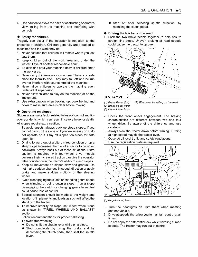
C Working1. Pull only from the drawbar. Never hitch to axle housing
or any other point except drawbar; such arrangementswill increase the risk of serious personal injury or deathdue to a tractor upset.
2. For trailing PTO-driven implements, set the drawbar tothe towing position.
3. Attach pulled or towed loads to the drawbar only.4. Keep all shields and guards in place. Replace any that
are missing or damaged. 5. Avoid sudden starts. To avoid upsets, slow down
when turning, on uneven ground, and before stopping. 6. The tractor cannot turn with the rear wheel or 4-wheel
differential locked and attempting to do so could bedangerous.
7. Do not operate near ditches, holes, embankments, orother ground surface features which may collapseunder the tractor's weight. The risk of tractor upset iseven higher when the ground is loose or wet. Tallgrass can hide obstacles, walk the area first to be sure.
8. Watch where you are going at all times. Watch for andavoid obstacles. Be alert at row ends, near trees, andother obstructions.
9. When working in groups, always let the others knowwhat you are going to do before you do it.
10.Never try to get on or off a moving tractor. 11.Always sit in the operator's seat when operating levers
or controls. 12.Do not use "Bi-speed Turn" at high speed.13. "Bi-Speed Turn" enables short and fast turns,
therefore, become familiar with its performance beforeoperating in close or confined areas.
14.Do not stand between tractor and implement or trailedvehicle unless parking brake is applied.
C Instructional seat (if equipped)1. Instructional seat is provided only for training and
instructing operators or diagnosing machine problems.2. It is not intended to carry children nor any other person
for any other purpose.3. Always wear your seat belt and stabilize your body by
holding the handrail on the CAB frame.
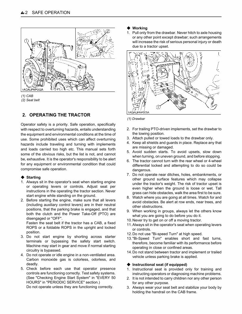
(1) CAB(2) Seat belt
2. OPERATING THE TRACTOR(1) Drawbar
-3SAFE OPERATION
4. Use caution to avoid the risks of obstructing operator'sview, falling from the machine and interfering withcontrols.
C Safety for childrenTragedy can occur if the operator is not alert to thepresence of children. Children generally are attracted tomachines and the work they do.1. Never assume that children will remain where you last
saw them.2. Keep children out of the work area and under the
watchful eye of another responsible adult.3. Be alert and shut your machine down if children enter
the work area.4. Never carry children on your machine. There is no safe
place for them to ride. They may fall off and be runover or interfere with your control of the machine.
5. Never allow children to operate the machine evenunder adult supervision.
6. Never allow children to play on the machine or on theimplement.
7. Use extra caution when backing up. Look behind anddown to make sure area is clear before moving.
C Operating on slopesSlopes are a major factor related to loss-of-control and tip-over accidents, which can result in severe injury or death.All slopes require extra caution. 1. To avoid upsets, always back up steep slopes. If you
cannot back up the slope or if you feel uneasy on it, donot operate on it. Stay off slopes too steep for safeoperation.
2. Driving forward out of a ditch, mired condition or up asteep slope increases the risk of a tractor to be upsetbackward. Always back out of these situations. Extracaution is required with four-wheel drive modelsbecause their increased traction can give the operatorfalse confidence in the tractor's ability to climb slopes.
3. Keep all movement on slopes slow and gradual. Donot make sudden changes in speed, direction or applybrake and make sudden motions of the steeringwheel.
4. Avoid disengaging the clutch or changing gears speedwhen climbing or going down a slope. If on a slopedisengaging the clutch or changing gears to neutralcould cause loss of control.
5. Special attention should be made to the weight andlocation of implements and loads as such will affect thestability of the tractor.
6. To improve stability on slope, set widest wheel treadas shown in "TIRES, WHEELS AND BALLAST"section.Follow recommendations for proper ballasting.
7. To avoid free wheeling:A Do not shift the shuttle lever while on a slope.A Stop completely by using the brake and by
depressing the clutch pedal, then shift the shuttlelever.
A Start off after selecting shuttle direction, byreleasing the clutch pedal.
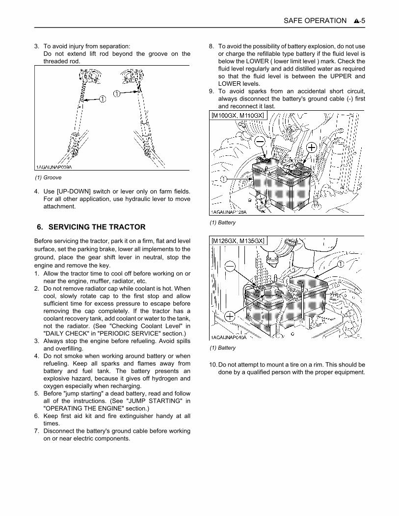
C Driving the tractor on the road 1. Lock the two brake pedals together to help assure
straight-line stops. Uneven braking at road speedscould cause the tractor to tip over.
2. Check the front wheel engagement. The brakingcharacteristics are different between two and fourwheel drive. Be aware of the difference and usecarefully.
3. Always slow the tractor down before turning. Turningat high speed may tip the tractor over.
4. Observe all local traffic and safety regulations.Use the registration plate as required.
5. Turn the headlights on. Dim them when meetinganother vehicle.
6. Drive at speeds that allow you to maintain control at alltimes.
7. Do not apply the differential lock while traveling at roadspeeds. The tractor may run out of control.
(1) Brake Pedal (LH)(2) Brake Pedal (RH)(3) Brake Pedal Lock
(A) Whenever travelling on the road
(1) Registration plate

SAFE OPERATION-4
8. Avoid sudden motions of the steering wheel as theycan lead to a dangerous loss of stability. The risk isespecially great when the tractor is traveling at roadspeeds.
9. Do not operate an implement while the tractor is on theroad. Lock the 3-point hitch in the raised position.
10.Set the implement lowering control in the "LOCK"position to hold the implement in the raised position.
1. Disengage the PTO, lower all implements to theground, place all control levers in their neutralpositions, set the parking brake, stop the engine,remove the key from the ignition and lock the cab door(if equipped). Leaving transmission in gear with theengine stopped will not prevent tractor from rolling.
2. Make sure that the tractor has come to a completestop before dismounting.
3. Avoid parking on steep slopes, if at all possible park ona firm and level surface; if not, park across a slope withchock the wheels.Failure to comply with this warning may allow thetractor to move and could cause injury or death.
1. Wait until all moving components have completelystopped before getting off the tractor, connecting,disconnecting, adjusting, cleaning, or servicing anyPTO driven equipment.
2. Keep the PTO shaft cover in place at all times.Replace the PTO shaft cap when the shaft is not inuse.
3. Before installing or using PTO driven equipment, readthe manufacturer's manual and review the safetylabels attached to the equipment.To prevent PTO driven equipment from improper orunsafe use, select the lower speed (540rpm) unlessthe higher one is specifically recommended as safe bythe equipment manufacture.
4. When operating stationary PTO driven equipment,always apply the tractor parking brake and placechocks behind and in front of the rear wheels. Stayclear of all rotating parts. Never step over rotatingparts.
1. Use the 3-point hitch only with equipment designed for3-point hitch usage.
2. When using a 3-point hitch mounted implement, besure to install the proper counterbalance weight on thefront of the tractor.
(1) 3-point hitch lowering lock lever (A) "LOCK"(B) "UNLOCK"
3. PARKING THE TRACTOR
4. OPERATING THE PTO
(1) PTO Shaft cover(2) PTO Shaft cap
(A) "NORMAL POSITION"(B) "RAISED POSITION"
5. USING 3-POINT HITCH
-5SAFE OPERATION
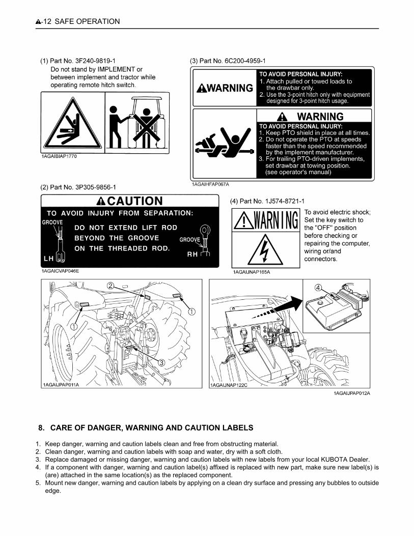
3. To avoid injury from separation:Do not extend lift rod beyond the groove on thethreaded rod.
4. Use [UP-DOWN] switch or lever only on farm fields.For all other application, use hydraulic lever to moveattachment.
Before servicing the tractor, park it on a firm, flat and levelsurface, set the parking brake, lower all implements to theground, place the gear shift lever in neutral, stop theengine and remove the key. 1. Allow the tractor time to cool off before working on or
near the engine, muffler, radiator, etc. 2. Do not remove radiator cap while coolant is hot. When
cool, slowly rotate cap to the first stop and allowsufficient time for excess pressure to escape beforeremoving the cap completely. If the tractor has acoolant recovery tank, add coolant or water to the tank,not the radiator. (See "Checking Coolant Level" in"DAILY CHECK" in "PERIODIC SERVICE" section.)
3. Always stop the engine before refueling. Avoid spillsand overfilling.
4. Do not smoke when working around battery or whenrefueling. Keep all sparks and flames away frombattery and fuel tank. The battery presents anexplosive hazard, because it gives off hydrogen andoxygen especially when recharging.
5. Before "jump starting" a dead battery, read and followall of the instructions. (See "JUMP STARTING" in"OPERATING THE ENGINE" section.)
6. Keep first aid kit and fire extinguisher handy at alltimes.
7. Disconnect the battery's ground cable before workingon or near electric components.
8. To avoid the possibility of battery explosion, do not useor charge the refillable type battery if the fluid level isbelow the LOWER ( lower limit level ) mark. Check thefluid level regularly and add distilled water as requiredso that the fluid level is between the UPPER andLOWER levels.
9. To avoid sparks from an accidental short circuit,always disconnect the battery's ground cable (-) firstand reconnect it last.
10.Do not attempt to mount a tire on a rim. This should bedone by a qualified person with the proper equipment.
(1) Groove
6. SERVICING THE TRACTOR(1) Battery
(1) Battery
SAFE OPERATION-6
11.Always maintain the correct tire pressure. Do notinflate tires above the recommended pressure shownin the operator's manual.
12.Securely support the tractor when either changingwheels or adjusting the wheel tread width.
13.Make sure that wheel bolts have been tightened to thespecified torque.
14.Disconnect the battery's ground cable and stop theengine to avoid the possibility of the machine runawaydue to 4WD braking system during testing, service orrepair with only rear wheels off the ground.
15.Do not work under any hydraulically supporteddevices. They can settle, suddenly leak down, or beaccidentally lowered. If it is necessary to work undertractor or any machine elements for servicing oradjustment, securely support them with stands orsuitable blocking beforehand.
16.Escaping hydraulic fluid under pressure has sufficientforce to penetrate skin, causing serious personalinjury. Before disconnecting hydraulic lines, be sure torelease all residual pressure. Before applyingpressure to the hydraulic system, make sure that allconnections are tight and that all lines, pipes, andhoses are free of damage.
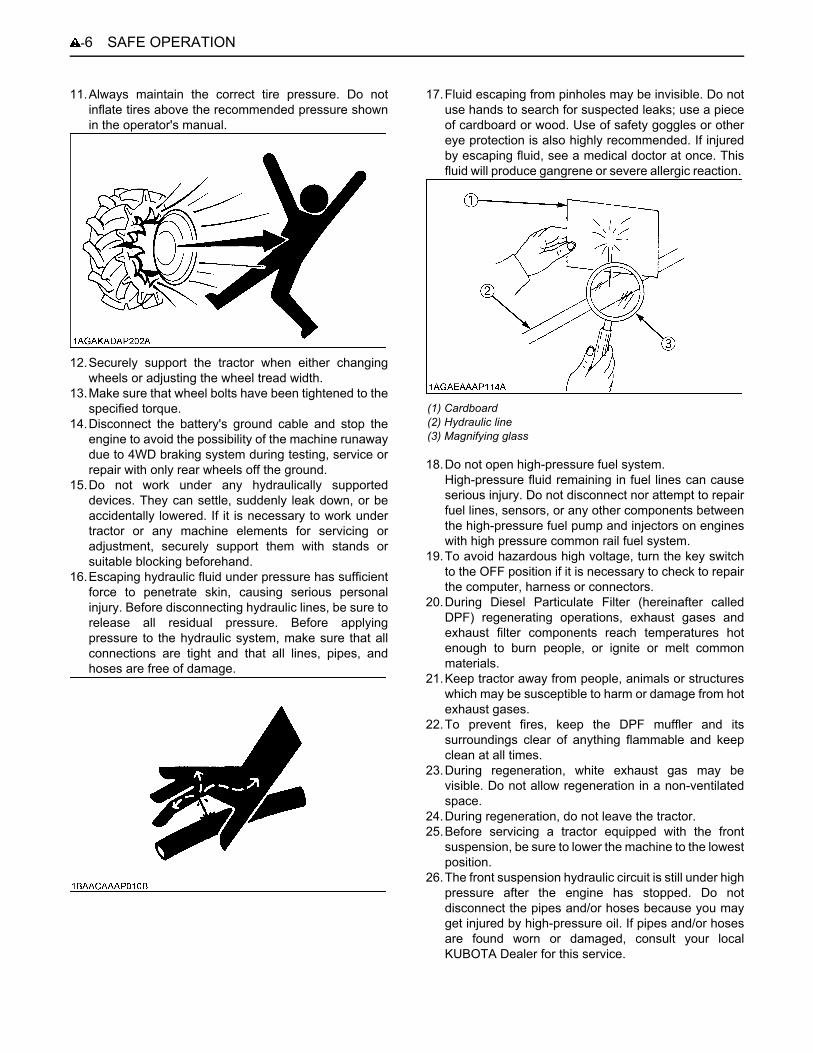
17.Fluid escaping from pinholes may be invisible. Do notuse hands to search for suspected leaks; use a pieceof cardboard or wood. Use of safety goggles or othereye protection is also highly recommended. If injuredby escaping fluid, see a medical doctor at once. Thisfluid will produce gangrene or severe allergic reaction.
18.Do not open high-pressure fuel system.High-pressure fluid remaining in fuel lines can causeserious injury. Do not disconnect nor attempt to repairfuel lines, sensors, or any other components betweenthe high-pressure fuel pump and injectors on engineswith high pressure common rail fuel system.
19.To avoid hazardous high voltage, turn the key switchto the OFF position if it is necessary to check to repairthe computer, harness or connectors.
20.During Diesel Particulate Filter (hereinafter calledDPF) regenerating operations, exhaust gases andexhaust filter components reach temperatures hotenough to burn people, or ignite or melt commonmaterials.
21.Keep tractor away from people, animals or structureswhich may be susceptible to harm or damage from hotexhaust gases.
22.To prevent fires, keep the DPF muffler and itssurroundings clear of anything flammable and keepclean at all times.
23.During regeneration, white exhaust gas may bevisible. Do not allow regeneration in a non-ventilatedspace.
24.During regeneration, do not leave the tractor.25.Before servicing a tractor equipped with the front
suspension, be sure to lower the machine to the lowestposition.
26.The front suspension hydraulic circuit is still under highpressure after the engine has stopped. Do notdisconnect the pipes and/or hoses because you mayget injured by high-pressure oil. If pipes and/or hosesare found worn or damaged, consult your localKUBOTA Dealer for this service.
(1) Cardboard(2) Hydraulic line(3) Magnifying glass
-7SAFE OPERATION
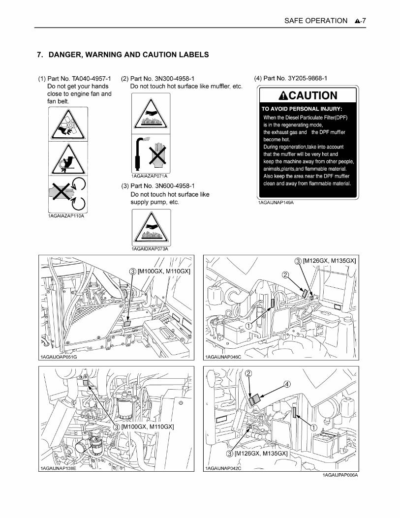
7. DANGER, WARNING AND CAUTION LABELS

SAFE OPERATION-8
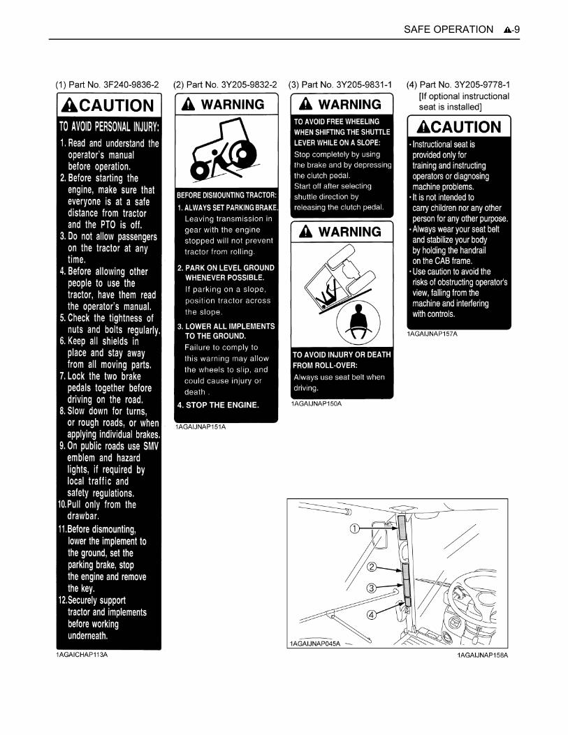
-9SAFE OPERATION
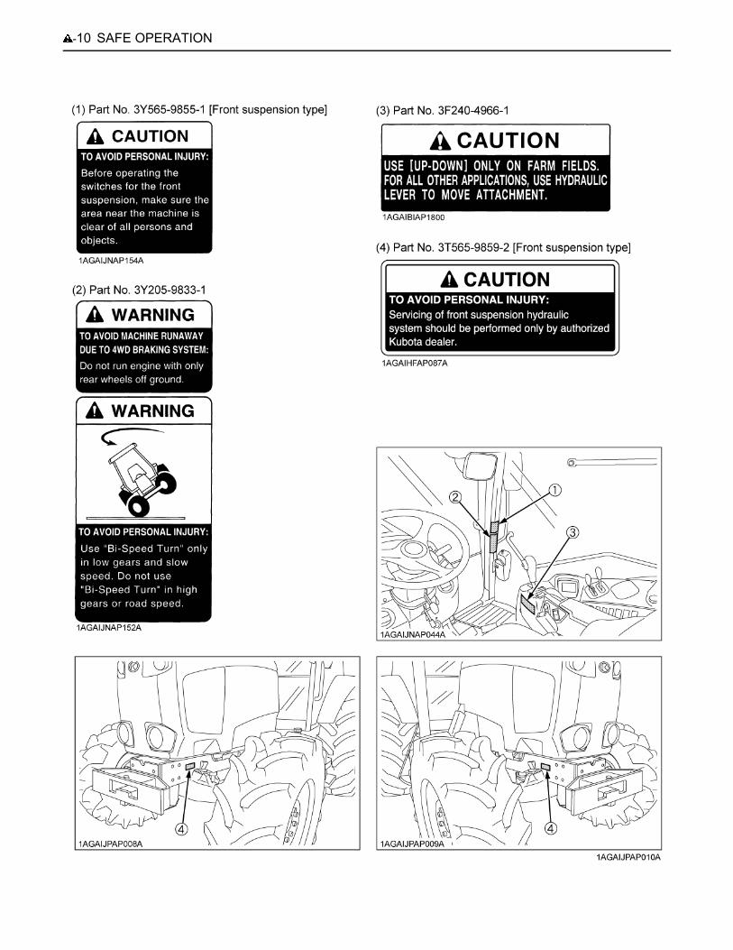
SAFE OPERATION-10
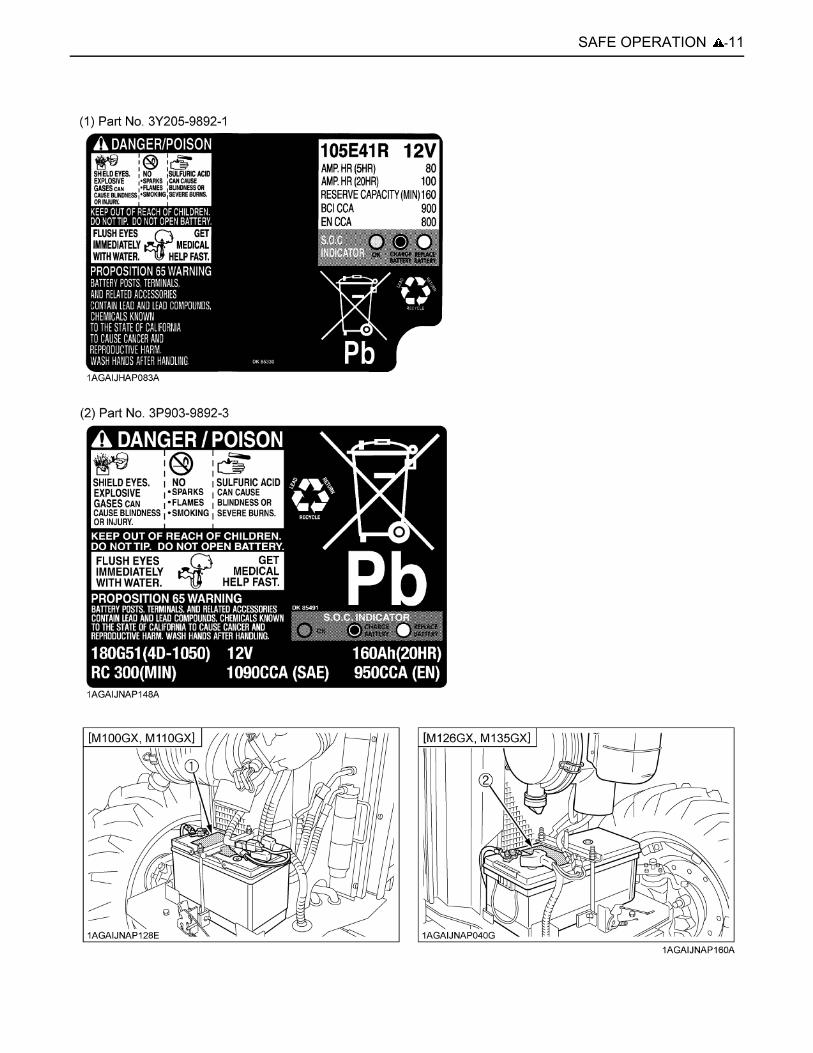
-11SAFE OPERATION
SAFE OPERATION-12
1. Keep danger, warning and caution labels clean and free from obstructing material.2. Clean danger, warning and caution labels with soap and water, dry with a soft cloth.3. Replace damaged or missing danger, warning and caution labels with new labels from your local KUBOTA Dealer.4. If a component with danger, warning and caution label(s) affixed is replaced with new part, make sure new label(s) is
(are) attached in the same location(s) as the replaced component.5. Mount new danger, warning and caution labels by applying on a clean dry surface and pressing any bubbles to outside
edge.
8. CARE OF DANGER, WARNING AND CAUTION LABELS
1SERVICING OF TRACTOR
SERVICING OF TRACTOR
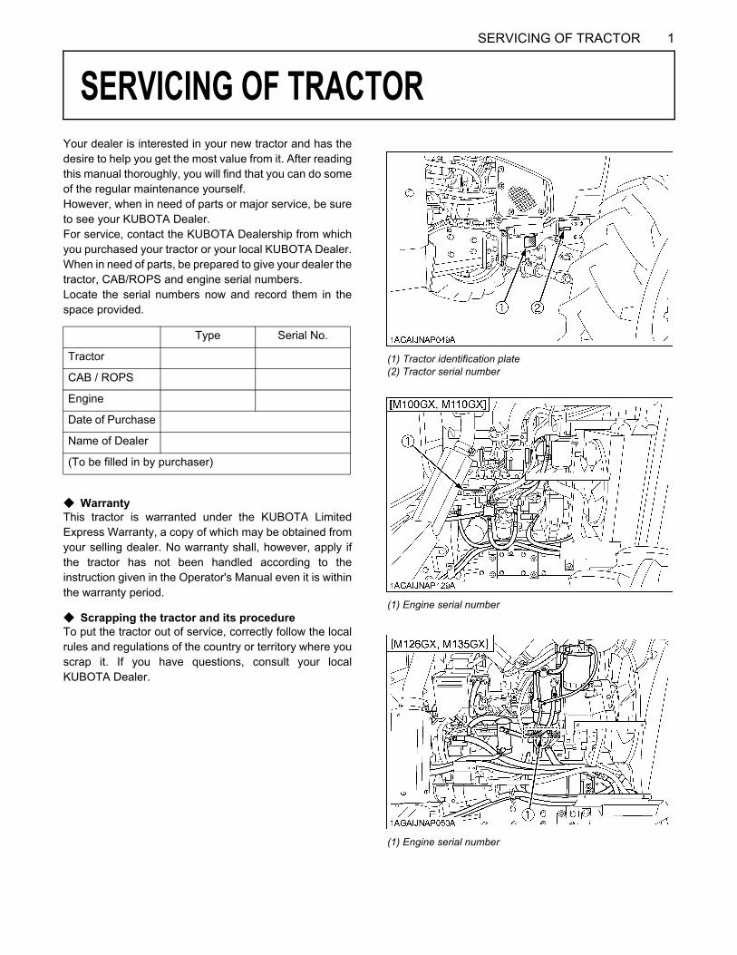
Your dealer is interested in your new tractor and has thedesire to help you get the most value from it. After readingthis manual thoroughly, you will find that you can do someof the regular maintenance yourself.However, when in need of parts or major service, be sureto see your KUBOTA Dealer.For service, contact the KUBOTA Dealership from whichyou purchased your tractor or your local KUBOTA Dealer.When in need of parts, be prepared to give your dealer thetractor, CAB/ROPS and engine serial numbers.Locate the serial numbers now and record them in thespace provided.C WarrantyThis tractor is warranted under the KUBOTA LimitedExpress Warranty, a copy of which may be obtained fromyour selling dealer. No warranty shall, however, apply ifthe tractor has not been handled according to theinstruction given in the Operator's Manual even it is withinthe warranty period.
C Scrapping the tractor and its procedureTo put the tractor out of service, correctly follow the localrules and regulations of the country or territory where youscrap it. If you have questions, consult your localKUBOTA Dealer.
Type Serial No.
Tractor
CAB / ROPS
Engine
Date of Purchase
Name of Dealer
(To be filled in by purchaser)
(1) Tractor identification plate(2) Tractor serial number
(1) Engine serial number
(1) Engine serial number
SERVICING OF TRACTOR2
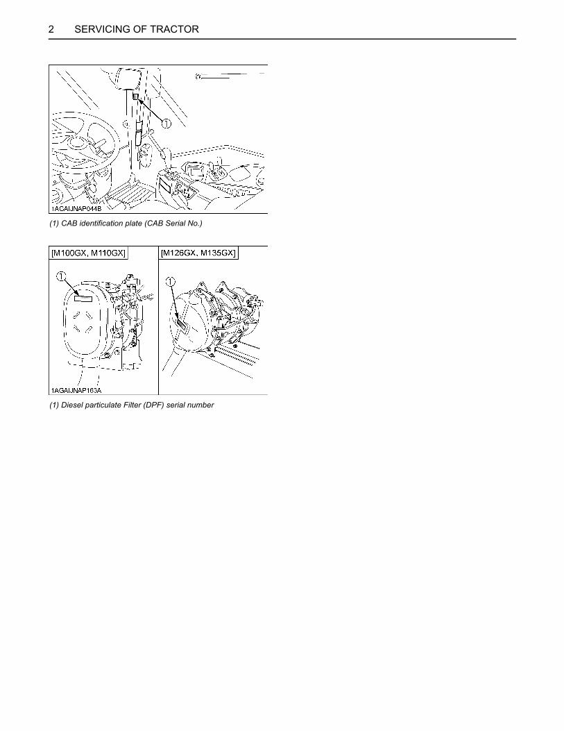
(1) CAB identification plate (CAB Serial No.)
(1) Diesel particulate Filter (DPF) serial number
3SPECIFICATIONS
SPECIFICATIONS
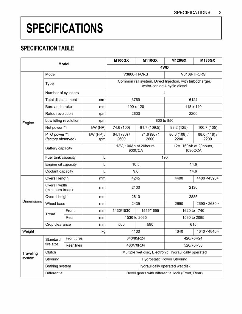
SPECIFICATION TABLEModelM100GX M110GX M126GX M135GX
4WD
Engine
Model V3800-TI-CRS V6108-TI-CRS
Type Common rail system, Direct Injection, with turbocharger,water-cooled 4 cycle diesel
Number of cylinders 4
Total displacement cm 3769 6124
Bore and stroke mm 100 x 120 118 x 140
Rated revolution rpm 2600 2200
Low idling revolution rpm 800 to 850
Net power *1 kW (HP) 74.6 (100) 81.7 (109.5) 93.2 (125) 100.7 (135)
PTO power *1 (factory observed)
kW (HP) /rpm
64.1 (86) / 2600
71.6 (96) / 2600
80.6 (108) / 2200
88.0 (118) / 2200
Battery capacity 12V, 100Ah at 20hours, 900CCA
12V, 160Ah at 20hours, 1090CCA
Fuel tank capacity L 190
Engine oil capacity L 10.5 14.6
Coolant capacity L 9.6 14.6
Dimensions
Overall length mm 4245 4400 4400 <4390>
Overall width(minimum tread) mm 2100 2130
Overall height mm 2810 2885
Wheel base mm 2435 2690 2690 <2680>
TreadFront mm 1430/1530 1555/1655 1620 to 1740
Rear mm 1530 to 2035 1590 to 2085
Crop clearance mm 560 590 615
Weight kg 4100 4640 4640 <4840>
Traveling system
Standardtire size
Front tires 340/85R24 420/70R24
Rear tires 480/70R34 520/70R38
Clutch Multiple wet disc, Electronic Hydraulically operated
Steering Hydrostatic Power Steering
Braking system Hydraulically operated wet disk
Differential Bevel gears with differential lock (Front, Rear)
4 SPECIFICATIONS
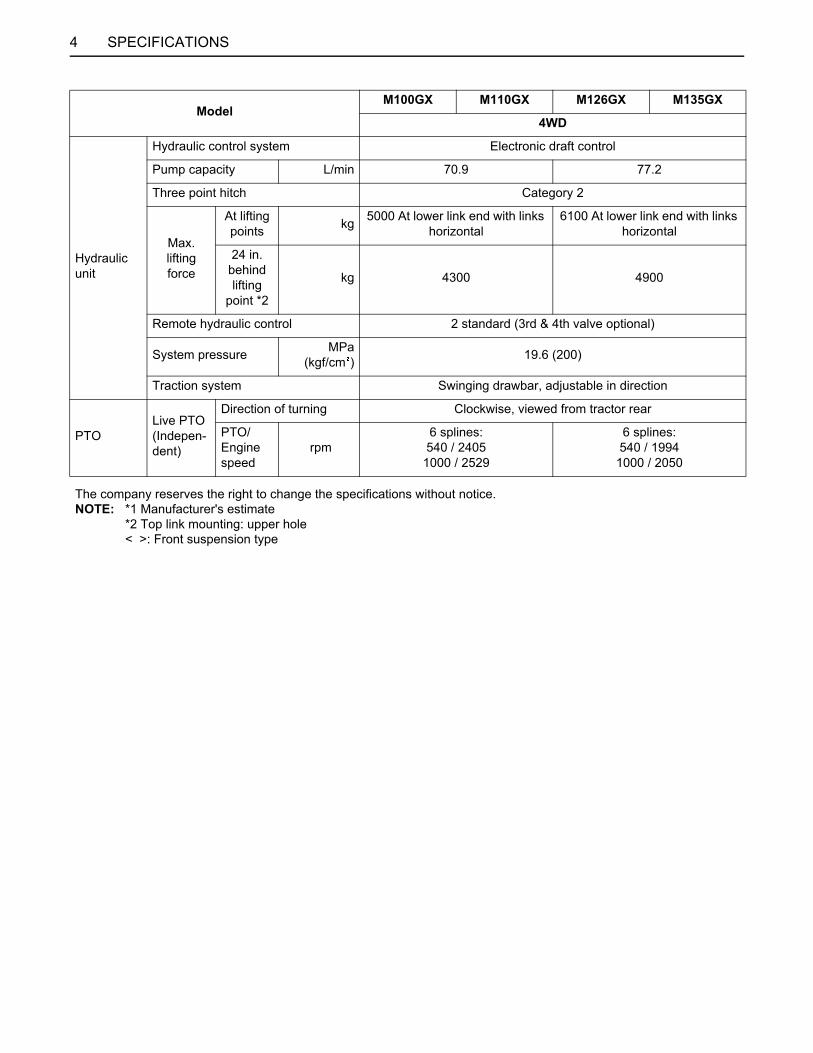
Hydraulic unit
Hydraulic control system Electronic draft control
Pump capacity L/min 70.9 77.2
Three point hitch Category 2
Max.liftingforce
At lifting points kg 5000 At lower link end with links
horizontal6100 At lower link end with links
horizontal
24 in. behind lifting
point *2
kg 4300 4900
Remote hydraulic control 2 standard (3rd & 4th valve optional)
System pressure MPa(kgf/cm ) 19.6 (200)
Traction system Swinging drawbar, adjustable in direction
PTOLive PTO(Indepen-dent)
Direction of turning Clockwise, viewed from tractor rear
PTO/Engine speed
rpm6 splines:540 / 2405
1000 / 2529
6 splines:540 / 1994
1000 / 2050
The company reserves the right to change the specifications without notice.NOTE: *1 Manufacturer's estimate
*2 Top link mounting: upper hole< >: Front suspension type
ModelM100GX M110GX M126GX M135GX
4WD

5SPECIFICATIONS
TRAVELING SPEEDS
The company reserves the right to change the specifications without notice.* At maximum engine rpm.
(At rated engine rpm)Model M100GX, M110GX M126GX, M135GX
Tire size (Rear) 480/70R34 520/70R38Range Speed (km/h) Speed (km/h)
C
1 0.19 0.202 0.23 0.243 0.28 0.294 0.36 0.365 0.40 0.416 0.49 0.507 0.59 0.618 0.74 0.74
L
1 0.80 0.842 0.98 1.023 1.20 1.244 1.50 1.515 1.67 1.746 2.05 2.127 2.49 2.578 3.13 3.13
M
1 3.40 3.552 4.17 4.313 5.08 5.244 6.37 6.385 7.08 7.396 8.67 8.977 10.57 10.898 13.26 13.28
H
1 9.4 9.82 11.5 11.93 14.0 14.54 17.6 17.65 19.6 20.46 23.9 24.87 29.2 30.1
8 * 36.6 36.7

6 IMPLEMENT LIMITATIONS
IMPLEMENT LIMITATIONS
The KUBOTA Tractor has been thoroughly tested for proper performance with implements sold or approved by KUBOTA.Use with implements which are not sold or approved by KUBOTA and which exceed the maximum specifications listedbelow, or which are otherwise unfit for use with the KUBOTA Tractor may result in malfunctions or failures of the tractor,damage to other property and injury to the operator or others. [Any malfunctions or failures of the tractor resulting from usewith improper implements are not covered by the warranty.]A Implement size may vary depending on soil operating conditions.A Strictly follow the instructions outlined in the operator’s manual of the mounted or trailed machinery or trailer, and do
not operate the combination tractor - machine or tractor - trailer unless all instructions have been followedA Forestry Application
Following hazards exist;(a) toppling trees, primarily in case a rear-mounted tree grab-crane is mounted at the rear of the tractor;(b) penetrating objects in the operator’s enclosure, primarily in case a winch is mounted at the rear of the tractor.Optional equipments such as OPS (Operator Protective Structure), FOPS (Falling Object Protective Structure), etc. todeal with these hazards and other related hazards are not available for this tractor. Without such optional equipmentuse is limited to tractor specific applications like transport and stationary work.
Tread (max. width) Operating condition Lower link end max. lifting
capacity W 0Front Rear
M100GX 1530 mm2035 mm IMPORTANT
A Tractor with front spaceroption is not approved foruse with front loader.
5000 kgM110GX 1655 mm
M126GXM135GX 1740 mm 2085 mm 6100 kg
Actual figures
Implement weight W 1and / or size Max. Drawbar Load W 2 Trailer loading weight W 3
Max. capacity
As in the following list(Shown on the next page) 1500 kg (3300 lbs.)
7000 kg (15400 lbs.)
8000 kg (17600 lbs.)
Lower link end max,hydraulic lifting capacity................. W 0Implement weight...........................The implement's weight which can be put on the lower link: W 1Max. drawbar load..........................W 2Trailer loading weight......................The max. loading weight for trailer (without trailer's weight): W 3
7IMPLEMENT LIMITATIONS
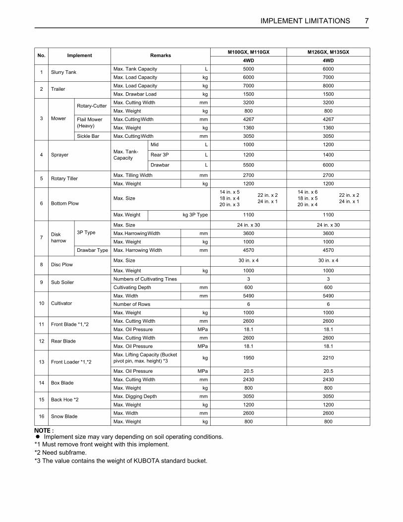
A Implement size may vary depending on soil operating conditions.*1 Must remove front weight with this implement.*2 Need subframe.*3 The value contains the weight of KUBOTA standard bucket.
No. Implement Remarks M100GX, M110GX M126GX, M135GX4WD 4WD
1 Slurry Tank Max. Tank Capacity L 5000 6000
Max. Load Capacity kg 6000 7000
2 Trailer Max. Load Capacity kg 7000 8000
Max. Drawbar Load kg 1500 1500
3 Mower
Rotary-Cutter Max. Cutting Width mm 3200 3200
Max. Weight kg 800 800
Flail Mower(Heavy)
Max. Cutting Width mm 4267 4267
Max. Weight kg 1360 1360
Sickle Bar Max. Cutting Width mm 3050 3050
4 Sprayer Max. Tank-Capacity
Mid L 1000 1200
Rear 3P L 1200 1400
Drawbar L 5500 6000
5 Rotary Tiller Max. Tilling Width mm 2700 2700
Max. Weight kg 1200 1200
6 Bottom PlowMax. Size
14 in. x 518 in. x 420 in. x 3
22 in. x 224 in. x 1
14 in. x 618 in. x 520 in. x 4
22 in. x 224 in. x 1
Max. Weight kg 3P Type 1100 1100
7 Disk harrow
3P TypeMax. Size 24 in. x 30 24 in. x 30
Max. Harrowing Width mm 3600 3600
Max. Weight kg 1000 1000
Drawbar Type Max. Harrowing Width mm 4570 4570
8 Disc PlowMax. Size 30 in. x 4 30 in. x 4
Max. Weight kg 1000 1000
9 Sub Soiler Numbers of Cultivating Tines 3 3
Cultivating Depth mm 600 600
10 CultivatorMax. Width mm 5490 5490
Number of Rows 6 6
Max. Weight kg 1000 1000
11 Front Blade *1,*2 Max. Cutting Width mm 2600 2600
Max. Oil Pressure MPa 18.1 18.1
12 Rear Blade Max. Cutting Width mm 2600 2600
Max. Oil Pressure MPa 18.1 18.1
13 Front Loader *1,*2Max. Lifting Capacity (Bucket pivot pin, max. height) *3 kg 1950 2210
Max. Oil Pressure MPa 20.5 20.5
14 Box Blade Max. Cutting Width mm 2430 2430
Max. Weight kg 800 800
15 Back Hoe *2Max. Digging Depth mm 3050 3050
Max. Weight kg 1200 1200
16 Snow Blade Max. Width mm 2600 2600
Max. Weight kg 800 800
8 INSTRUMENT PANEL AND CONTROLS
INSTRUMENT PANEL AND CONTROLS
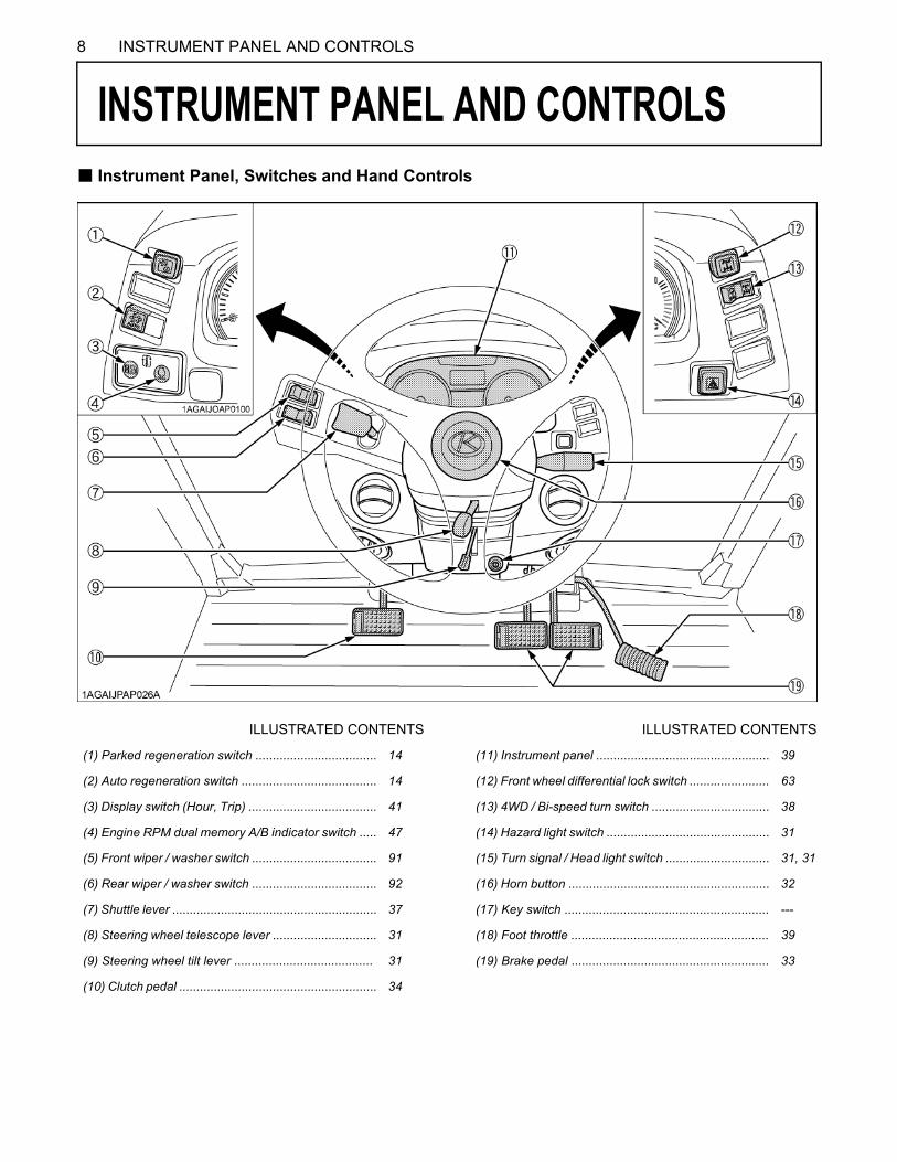
B Instrument Panel, Switches and Hand ControlsILLUSTRATED CONTENTS ILLUSTRATED CONTENTS
(1) Parked regeneration switch ................................... 14 (11) Instrument panel .................................................. 39
(2) Auto regeneration switch ....................................... 14 (12) Front wheel differential lock switch ....................... 63
(3) Display switch (Hour, Trip) ..................................... 41 (13) 4WD / Bi-speed turn switch .................................. 38
(4) Engine RPM dual memory A/B indicator switch ..... 47 (14) Hazard light switch ............................................... 31
(5) Front wiper / washer switch .................................... 91 (15) Turn signal / Head light switch .............................. 31, 31
(6) Rear wiper / washer switch .................................... 92 (16) Horn button .......................................................... 32
(7) Shuttle lever ........................................................... 37 (17) Key switch ........................................................... ---
(8) Steering wheel telescope lever .............................. 31 (18) Foot throttle ......................................................... 39
(9) Steering wheel tilt lever ........................................ 31 (19) Brake pedal ......................................................... 33
(10) Clutch pedal ......................................................... 34
9INSTRUMENT PANEL AND CONTROLS
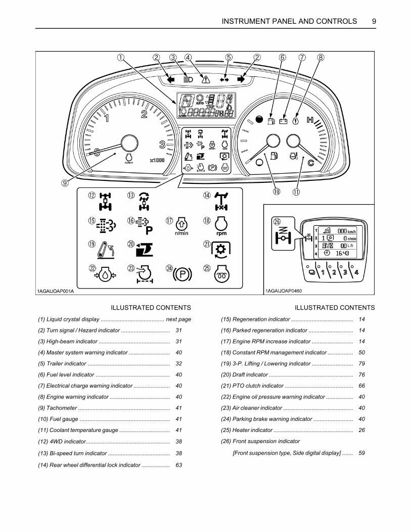
ILLUSTRATED CONTENTS ILLUSTRATED CONTENTS
(1) Liquid crystal display ........................................ next page (15) Regeneration indicator ....................................... 14
(2) Turn signal / Hazard indicator ............................... 31 (16) Parked regeneration indicator ............................ 14
(3) High-beam indicator ............................................. 31 (17) Engine RPM increase indicator .......................... 14
(4) Master system warning indicator .......................... 40 (18) Constant RPM management indicator ................ 50
(5) Trailer indicator .................................................... 32 (19) 3-P. Lifting / Lowering indicator .......................... 79
(6) Fuel level indicator ............................................... 40 (20) Draft indicator ..................................................... 76
(7) Electrical charge warning indicator ....................... 40 (21) PTO clutch indicator ........................................... 66
(8) Engine warning indicator ...................................... 40 (22) Engine oil pressure warning indicator ................. 40
(9) Tachometer .......................................................... 41 (23) Air cleaner indicator ............................................ 40
(10) Fuel gauge ......................................................... 41 (24) Parking brake warning indicator ......................... 40
(11) Coolant temperature gauge ................................ 41 (25) Heater indicator .................................................. 26
(12) 4WD indicator..................................................... 38 (26) Front suspension indicator
(13) Bi-speed turn indicator ....................................... 38 [Front suspension type, Side digital display] ....... 59
(14) Rear wheel differential lock indicator .................. 63

10 INSTRUMENT PANEL AND CONTROLS
C Liquid Crystal Display
No. Message DescriptionRefer-ence page
(1) Displays "F", "R" or "N". "F" is displayed when forward operation is selected with the shuttle lever.
"R" is displayed when reverse operation is selected.("N" is displayed when the lever is in the neutral position.)
37
(2) AUTO MODE (Automatic speed change)
Lights up when Travel mode or Field mode is selected.Turns off when Travel mode and Field mode are not selected.
51
(3) Displays "1" - "8" or "E". Displays the number of the Power shift ratios that was selected with the Up-shift/Down-shift button. "E" appears in case of gear shift error. 35
(4) Displays "L", "M", "H", "C", or "N".
Displays the position of the range gear shift that was selected with the Power shift/Range shift lever. "C" appears when the creep speed is selected (option). 35
(5) (6)
Light up when the Rev-limiter control has been set.(Display flashes when the engine speed is at or below the set speed.) 47
(6) Lights up when the RPM dual memory has been set. 47
(7)
Depending on the settings, the below messages are displayed.1. Elapsed time (hour meter) 4. Maximum engine speed that is set by the2. Trip time Rev- limiter control3. Engine speed that is set in memory 5. Failure information or other information
41
(8) TRIP Lights up when trip time mode is selected. 41
(9) Displays "h", "A", "B", or "L".
"h" is displayed when the hour meter or trip time is selected."A" or "B" is displayed when the RPM dual memory is set."L" is displayed when the Rev-limiter control has been set.
414747
(10) Displays "0" - "99". Digital display of the lift arm height. ---
11INSTRUMENT PANEL AND CONTROLS
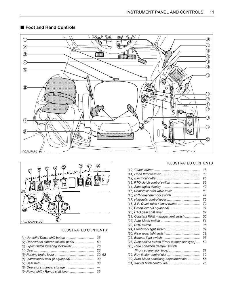
B Foot and Hand Controls
ILLUSTRATED CONTENTS
(10) Clutch button .................................................. 35(11) Hand throttle lever .......................................... 39(12) Electrical outlet ............................................... 96(13) PTO clutch control switch ................................ 66(14) Side digital display .......................................... 42(15) Remote control valve lever .............................. 80(16) RPM dual memory switch ............................... 47(17) Hydraulic control lever .................................... 75(18) 3-P. Quick raise / lower switch ........................ 79(19) Creep lever (if equipped) ................................. 37(20) PTO gear shift lever ........................................ 67(21) Constant RPM management switch ................ 50(22) Auto-Mode switch ........................................... 51(23) DHC switch ..................................................... 36
ILLUSTRATED CONTENTS (24) Front work light switch ..................................... 32(25) Rear work light switch ..................................... 32
(1) Up-shift / Down-shift button ............................... 35 (26) Beacon light switch ......................................... 97(2) Rear wheel differential lock pedal ..................... 63 (27) Suspension switch [Front suspension type] .... 59(3) 3-point hitch lowering lock lever ........................ 78 (28) Ride condition damper switch(4) Seat .................................................................. 28 [Front suspension type] .................................. 61(5) Parking brake lever ........................................... 39, 62 (29) Rev-limiter control dial .................................... 39(6) Instructional seat (if equipped).......................... 30 (30) Auto-Mode sensitivity adjustment dial ............. 56(7) Seat belt ........................................................... 30 (31) 3-point hitch control dial .................................. 75(8) Operator's manual storage ............................... ---(9) Power shift / Range shift lever ........................... 35

12 INSTRUMENT PANEL AND CONTROLS
ILLUSTRATED CONTENTS
(1) Remote hitch Up / Down switch ................ 71
(2) Remote control valve coupler ................... 80
(3) Trailer electrical outlet .............................. 65
13PRE-OPERATION CHECK
PRE-OPERATION CHECK
DAILY CHECKTo prevent trouble from occurring, it is important to knowthe condition of the tractor well. Check it before starting.To avoid personal injury:A Be sure to check and service the tractor on a
level surface with the engine shut off and theparking brake "ON" and implement lowered tothe ground.
Check item- Walk around inspection- Check engine oil level- Check transmission oil level- Check coolant level- Check water separator- Clean grill, radiator and screen- Check DPF muffler- Check air cleaner evacuator valve (When used in a dusty place)- Check brake pedal- Check parking brake lever- Check indicators, gauges and meter- Check lights- Check seat belt- Check movable parts- Refuel
(See "DAILY CHECK" in "PERIODIC SERVICE"section.)
- Care of danger, warning and caution labels (See "DANGER, WARNING AND CAUTION LABELS"in "SAFE OPERATION" section.)
14 OPERATING THE ENGINE
OPERATING THE ENGINE
To avoid personal injury:A Read "Safe Operation" in the front of this
manual.A Read the danger, warning and caution labels
located on the tractor.A To avoid the danger of exhaust fume
poisoning, do not operate the engine in aclosed building without proper ventilation.
A Never start engine while standing on ground.Start engine only from operator's seat.
A Make it a rule to set all shift levers to the"NEUTRAL" positions and to place PTO clutchcontrol switch in "OFF" position before startingthe engine.
A When the engine is started, the machine heightmay change unexpectedly. Before starting thetractor, make sure the area near the machine isclear of all persons and objects. [Frontsuspension type].
A Do not use starting fluid or ether.A To protect the battery and the starter, make sure that
the starter is not continuously turned for more than 10seconds.
EXHAUST AFTERTREATMENT DEVICES
To avoid personal injury:A During Diesel Particulate Filter (DPF)
regenerating operations, exhaust gases andexhaust filter components reach temperatureshot enough to burn people, or ignite or meltcommon materials.
A Keep tractor away from people, animals orstructures which may be susceptible to harmor damage from hot exhaust gases.
A During regeneration, white exhaust gases maybe visible. Do not allow regeneration in a nonventilated garage or confined area.
A During regeneration, do not leave the tractor.
BDiesel Oxidation Catalyst and Diesel Particulate Filter (DPF) Muffler
The Diesel Oxidation Catalyst and Diesel Particular Filter(Hereinafter called DPF) serves to reduce hydrocarbons,carbon monoxide and other toxic gases, all of which arecontained in diesel engine emissions, to harmless carbondioxide and water. The DPF also traps Particulate Matter(PM).To meet the emission regulations in your country, the DPFis installed on your tractor.Be sure to read this operator's manual before running inyour tractor.It is imperative for the tractor owner and operator tohandle the DPF in a safe and environmentally responsiblemanner.
A When the DPF has trapped a specific amount ofparticulate matter (PM), the engine computer startsthe process of regeneration or burning of sootcollected by the filter.This burning process is called regeneration.
(1) Diesel Particulate Filter (DPF)
15OPERATING THE ENGINE
BHandling PointsC FuelBe sure to use Ultra Low Sulfur Fuel (S15).
A Use of diesel fuel other than Ultra Low Sulfur Fuel mayadversely affect the engine and DPF performance.Use of fuels other than Ultra Low Sulfur Fuel (S15)may not meet regulations for your region.
C Engine oilUse DPF-compatible oil (CJ-4) for the engine.
A If any engine oil other than CJ-4 is used, the DPF maybecome clogged earlier than expected and the fueleconomy may drop.
BDPF Regeneration ProcessThis system has "Parked Regeneration" in which the DPFregenerates while the tractor is parked and "AutomaticRegeneration" which the DPF can regenerateautomatically while working.When key switch is turned ON, the tractor will be in the"Inhibit Mode". By pressing the auto regeneration switch,the mode can be switched to the "Auto RegenerationMode".Choose from them according to your job condition, usageenvironment and other factors.
C Parked Regeneration Mode;When an amount of PM more than specified has built upin the DPF, the indicator starts flashing to notify theoperator that Regeneration is required. Therefore, parkthe tractor in a safe place and carry out the regeneration.
C Auto Regeneration Mode;Press the auto regeneration switch, and the Auto Modeis activated.When an amount of PM more than specified has built upin the DPF muffler, the DPF is automatically regeneratedwhether the tractor is in motion or parked.For jobs not affected by hot gases emitted out of the DPFmuffler during regeneration, the Auto Mode is advisable.
C Inhibit Mode;The tractor has been set to Inhibit Mode by default.Even if an amount of PM more than specified has builtup in the DPF muffler, the DPF does not regenerate.When the regeneration is needed, the indicator startsflashing to notify the operator to active either AutoRegeneration Mode or conduct a Parked RegenerationMode, once in a safe area.For jobs that are done in poorly ventilated area or in areathat may affect plants and animals because of hot gasesthat will be emitted, the Inhibit Mode is recommended.

16 OPERATING THE ENGINE
1. Park the tractor in a safe area away from buildings, people, and animals. 2. Apply the parking brake. 3. Set the power shift / range shift lever and the shuttle shift lever to the neutral position. 4. Turn "OFF" the PTO clutch control switch. 5. Return the engine rpm to the idle speed.
During the regeneration cycle, do not touch the above levers, and switches, nor change the engine rpm. Otherwise, theregeneration will be interrupted. Never leave the tractor when parked regeneration process is activated. OnceRegeneration process is complete, the tractor may be moved and returned to work.
A If the parked regeneration cycle is interrupted, the engine rpm is fixed at the idling level for about 30 seconds. For thisperiod, keep the hand throttle lever and foot throttle pedal at the idle position. Do not move them. They will functionagain in 30 seconds.
Operating Procedure for Parked Regeneration
6. Once the parked regeneration switch starts flashing.
7. Press the parked regeneration switch to start the regeneration cycle. (The switch light will remain "ON" constantly during the cycle.)
8. The engine rpm will automatically rise, and the regeneration process will begin.
9. Make sure the indicators stay "ON" while regenerating the DPF. They turn "OFF" when the cycle is complete. The tractor can be moved and continue working.
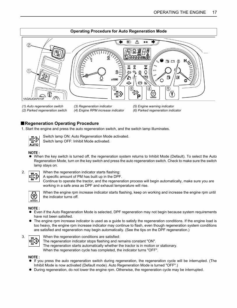
17OPERATING THE ENGINE
BRegeneration Operating Procedure 1. Start the engine and press the auto regeneration switch, and the switch lamp illuminates.
Operating Procedure for Auto Regeneration Mode
(1) Auto regeneration switch(2) Parked regeneration switch
(3) Regeneration indicator(4) Engine RPM increase indicator
(5) Engine warning indicator(6) Parked regeneration indicator
Switch lamp ON: Auto Regeneration Mode activated.Switch lamp OFF: Inhibit Mode activated.
A When the key switch is turned off, the regeneration system returns to Inhibit Mode (Default). To select the AutoRegeneration Mode, turn on the key switch and press the auto regeneration switch. Check to make sure the switchlamp stays on.
2. When the regeneration indicator starts flashing:A specific amount of PM has built up in the DPF.Continue to operate the tractor, and the regeneration process will begin automatically, make sure you are working in a safe area as DPF and exhaust temperature will rise.
When the engine rpm increase indicator starts flashing, keep on working and increase the engine rpm until the indicator turns off.
A Even if the Auto Regeneration Mode is selected, DPF regeneration may not begin because system requirementshave not been satisfied.
A The engine rpm increase indicator is used as a guide to satisfy the regeneration conditions. If the engine load istoo heavy, the engine rpm increase indicator may continue to flash, even though regeneration system conditionsare satisfied and regeneration may begin automatically. (See the tips on the DPF regeneration.)
3. When the regeneration conditions are satisfied:The regeneration indicator stops flashing and remains constant "ON". The regeneration starts automatically whether the tractor is in motion or stationary.When the regeneration cycle has completed, the indicator turns "OFF".
A If you press the auto regeneration switch during regeneration, the regeneration cycle will be interrupted. (TheInhibit Mode is now activated (Default mode). Auto Regeneration Mode is turned "OFF".)
A During regeneration, do not lower the engine rpm. Otherwise, the regeneration cycle may be interrupted.

18 OPERATING THE ENGINE
BPM Warning Level and Required ProceduresDuring Auto Regeneration Mode when the PM level has built up in the DPF, the regeneration cycle will begin automatically.If the regeneration cycle is interrupted or the regeneration conditions are not satisfied, the buzzer starts sounding and theindicator display changes in response to the PM level in order to prompt the operator to perform the required procedurelisted below.
A Once the regeneration level has been reached, immediately perform the required procedure for regeneration.Interrupting the regeneration cycle or continued operation by ignoring the warning signs may cause DPF and enginedamage.
Auto ModeDPF system status Required procedure
PM warning level: 1
Buzzer: Not sounding
The regeneration indicator starts flashing. A specific amount of PM has accumulatedin the DPF muffler.Continue to work the tractor to raise the DPF temperature.
The RPM increase indicator startsflashing.
Continue the work and increase the enginerpm until the indicator turns "OFF".
The regeneration indicator will stopflashing and remain "ON" constantly.
The regeneration cycle begins until cycle iscomplete then the indicator will turn "OFF".
PM warning level: 2-1
Buzzer: Sounding every 5 seconds
If the regeneration cycle was interrupted or conditions are not satisfied for regeneration then DPFsystem in now in Level 2.
The regeneration indicator starts flashing. Start the regeneration, referring to "PM warning level: 1" above.Now the parked regeneration indicator starts flashing, and the parked regeneration can also be started.If the regeneration conditions are not met, perform the parked regeneration.A For the procedure, refer to "Operating
Procedure for Parked Regeneration".
The RPM increase indicator starts flashing.
PM warning level: 2-2
Buzzer: Sounding every 3 seconds The parked regeneration indicator starts
flashing.
PM warning level: 3
Buzzer: Constantly SoundsEngine output: 50%
If the regeneration fails in the warning level 2:The engine warning indicator starts flashing.
Immediately discontinue working the tractor and begin the parked regeneration cycle process.A For the procedure, refer to "Operating
Procedure for Parked Regeneration".At this PM warning level, the Auto Regeneration Mode does not function.If the tractor is operated further, the regeneration cycle will be disabled.
The parked regeneration indicator starts flashing.
The auto regeneration switch lamp turns "OFF".
PM warning level: 4
Buzzer: Constantly SoundsEngine output: 50%
If the parked regeneration is interrupted or the tractor is continuously operated in the warning level 3:
The engine warning indicator remains constantly "ON".
Immediately move the tractor to a safeplace and park it there and turn the engine"OFF".Contact your local KUBOTA Dealer.A At this level, never continue to operate
the tractor otherwise damage will resultto the DPF and engine.

19OPERATING THE ENGINE
BRegeneration Operating Procedure 1. Start the engine and make sure that the auto regeneration switch lamp is "OFF".
Operating Procedure for Inhibit Mode
(1) Auto regeneration switch(2) Parked regeneration switch
(3) Regeneration indicator(4) Engine RPM increase indicator
(5) Engine warning indicator(6) Parked regeneration indicator
Switch lamp OFF: Inhibit Mode selected.Switch lamp ON: Auto Mode selected.
2. When the parked regeneration indicator starts flashing, follow the "Operating Procedure for Parked Regeneration" procedure.

20 OPERATING THE ENGINE
BPM Warning Level and Required ProceduresIn the Inhibit Mode, the buzzer starts sounding and the indicator display changes in response to the PM level in order toprompt the operator to perform the required procedure listed below.
A Once the regeneration level has been reached, immediately perform the required procedure for regeneration.Interrupting the regeneration cycle or continued operation by ignoring the warning signs may cause DPF and enginedamage.
Inhibit Mode
DPF system status Required procedure
PM warning level: 1
Buzzer: Not sounding
The indicator starts flashing. A specific level of PM has built up in theDPF muffler.
Regeneration with the Auto Mode is possible. If the regeneration conditions are met, select the Auto Mode. Refer to "Operating Procedure for Auto Regeneration Mode".
PM warning level: 2-1
Buzzer: Sounding every 5 seconds
Parked regeneration indicator starts flashing.
Move the tractor to a safe area, then follow the "Operating Procedure for Parked Regeneration".
PM warning level: 2-2
Buzzer: Sounding every 3 seconds
PM warning level: 3
Buzzer: Constantly soundsEngine output: 50%
If the parked regeneration cycle is interrupted or the tractor is continuously operated in the PM warning level 2:
The engine warning indicator starts flashing.
Immediately stop working the tractor, move the tractor to a safe area, then follow the "Operating Procedure for Parked Regeneration".If the tractor is operated further and the operator ignores the warning signs, then regeneration will be disabled.
The parked regeneration indicator starts flashing
PM warning level: 4
Buzzer: Constantly soundsEngine output: 50%
If the regeneration cycle is interrupted or the tractor is continuously operated ignoring the warning signs, in the PM warning level 3:
The engine warning indicator remains constantly "ON".
Immediately move the tractor to a safe place and place in park, turn "OFF" engine.Contact your local KUBOTA Dealer.A At this level never continue to operate
the tractor, otherwise damage mayresult to the DPF and engine.

21OPERATING THE ENGINE
BTips on DPF RegenerationA Operation
The higher in speed or load the engine operates, thehigher the exhaust temperature rises. As a result,particulate matter (PM) inside the DPF is consumed,therefore the regeneration process occurs lessfrequently over time.The lower in speed or load the engine operates, thelower the exhaust temperature. Accordingly, lessparticulate matter (PM) inside the DPF is consumed,therefore more accumulation of PM will occur, whichrequires frequent regeneration, therefore avoidprolonged idling if possible.
A Auto Regeneration Mode specified conditionsIn order for the Auto Regeneration to begin, all of thelisted conditions must be satisfied. If any one of thelisted conditions are not satisfied, the process can notbegin.(1) The engine coolant temperature.(2) The DPF temperature.(3) The engine speed is around 1200 rpm or higher.
A Usually it takes 15-20 minutes to complete theregeneration cycle.It may depend on ambient temperature, exhausttemperature and engine speed.
A It is recommended to do the regenerating while theengine is warm.
A Do not unnecessarily start and interrupt theregeneration process. Otherwise, a small amount offuel becomes mixed with the engine oil, whichdegrades the oil quality.
A While the DPF is being regenerated, the engine airflow rate is automatically limited to keep up theexhaust temperature. Because of this the engine maysound differently, this is normal for this engine.
A Just after the regeneration has ended, the DPF mufflerremains hot. It is advisable to keep the engine runningfor about 5 minutes to allow cooling of the exhaustcomponents.
STARTING THE ENGINE
Pull the parking brake lever up to park.The parking brake indicator light on the EasyChecker(TM) will come on while the parking brake is set.
A If the tractor is operated with the parking brake set, theparking brake will be damaged.
1. Make sure the parking brake is set.
(1) Parking brake lever(2) Release button
(A) "PULL"
(1) Parking brake warning indicator
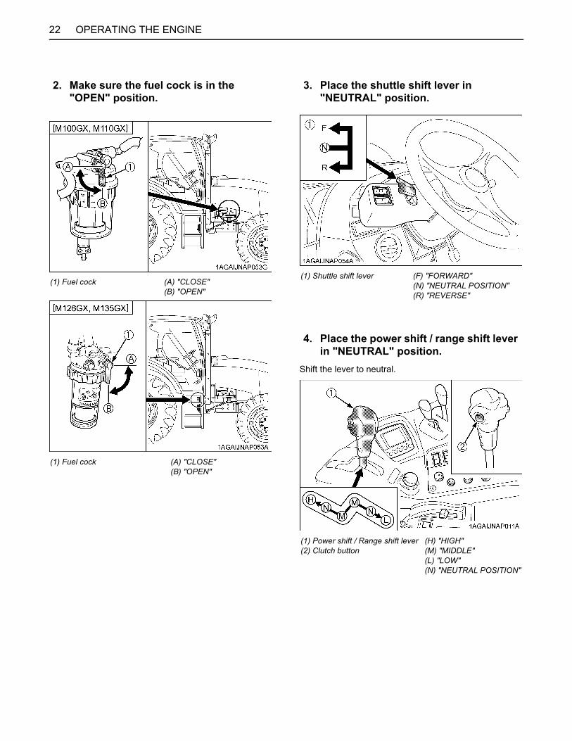
OPERATING THE ENGINE22
Shift the lever to neutral.
2. Make sure the fuel cock is in the "OPEN" position.
(1) Fuel cock (A) "CLOSE"(B) "OPEN"
(1) Fuel cock (A) "CLOSE"(B) "OPEN"
3. Place the shuttle shift lever in "NEUTRAL" position.
(1) Shuttle shift lever (F) "FORWARD"(N) "NEUTRAL POSITION"(R) "REVERSE"
4. Place the power shift / range shift lever in "NEUTRAL" position.
(1) Power shift / Range shift lever(2) Clutch button
(H) "HIGH"(M) "MIDDLE"(L) "LOW"(N) "NEUTRAL POSITION"

23OPERATING THE ENGINE
When the Rev-limiter control dial is set, the engine speedwill not exceed the speed that is set. Even when the handthrottle lever is operated. Turn the dial all the way to theright to the " " position.
5. Place the PTO clutch control switch in "OFF" position.
(1) PTO clutch control switch "ON" (Engaged) "OFF" (Disengaged)
(A) "PUSH"
6. Set the throttle lever at the minimum speed position.
(1)(2)
Hand throttle leverRev-limiter control dial
"INCREASE""DECREASE"
7. Insert the key into the key switch and turn it "ON".
"OFF" (Engine-Stop)
"ACC" (Electrical Power-accessories)
"ON" (Engine-Run)
"START" (Engine-Start)
NOTE:
ACC... A All the accessories can be used while theengine is stopped.
A Do not leave the key at "ACC" position. Thebattery will be quickly discharged. Turn itback to "OFF" after use.
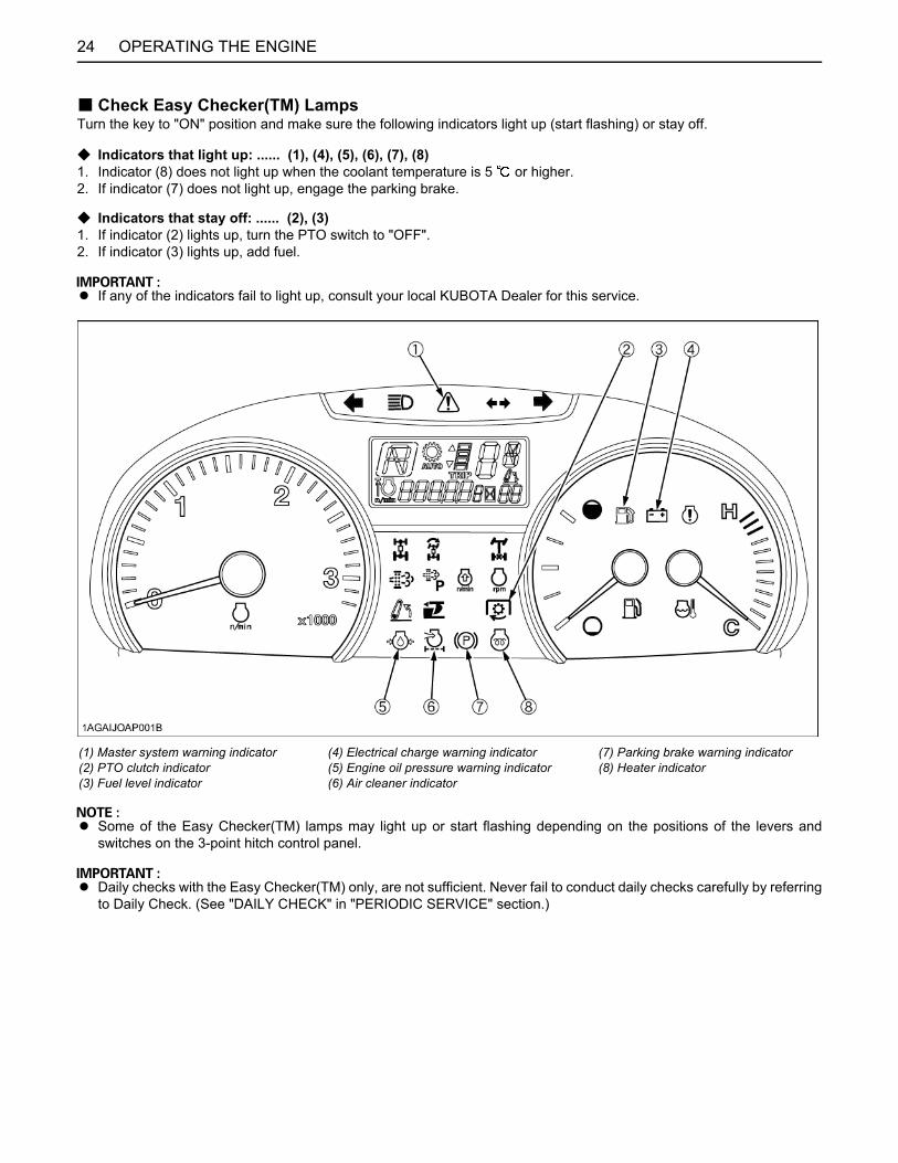
24 OPERATING THE ENGINE
B Check Easy Checker(TM) LampsTurn the key to "ON" position and make sure the following indicators light up (start flashing) or stay off.
C Indicators that light up: ...... (1), (4), (5), (6), (7), (8)1. Indicator (8) does not light up when the coolant temperature is 5 or higher.2. If indicator (7) does not light up, engage the parking brake.
C Indicators that stay off: ...... (2), (3)1. If indicator (2) lights up, turn the PTO switch to "OFF".2. If indicator (3) lights up, add fuel.
A If any of the indicators fail to light up, consult your local KUBOTA Dealer for this service.
A Some of the Easy Checker(TM) lamps may light up or start flashing depending on the positions of the levers andswitches on the 3-point hitch control panel.
A Daily checks with the Easy Checker(TM) only, are not sufficient. Never fail to conduct daily checks carefully by referringto Daily Check. (See "DAILY CHECK" in "PERIODIC SERVICE" section.)
(1) Master system warning indicator(2) PTO clutch indicator(3) Fuel level indicator
(4) Electrical charge warning indicator(5) Engine oil pressure warning indicator(6) Air cleaner indicator
(7) Parking brake warning indicator(8) Heater indicator
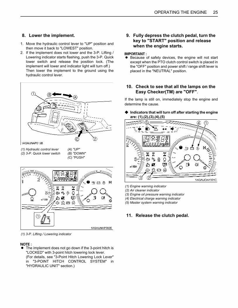
25OPERATING THE ENGINE
1. Move the hydraulic control lever to "UP" position andthen move it back to "LOWEST" position.
2. If the implement does not lower and the 3-P. Lifting /Lowering indicator starts flashing, push the 3-P. Quicklower switch and release the position lock. (Theimplement will lower and indicator light will turn off.)Then lower the implement to the ground using thehydraulic control lever.
A The implement does not go down if the 3-point hitch is"LOCKED" with 3-point hitch lowering lock lever.(For details, see "3-Point Hitch Lowering Lock Lever"in "3-POINT HITCH CONTROL SYSTEM" in"HYDRAULIC UNIT" section.)
A Because of safety devices, the engine will not startexcept when the PTO clutch control switch is placed inthe "OFF" position and power shift / range shift lever isplaced in the "NEUTRAL" position.
If the lamp is still on, immediately stop the engine anddetermine the cause.
C Indicators that will turn off after starting the engineare: (1),(2),(3),(4),(5)
8. Lower the implement.
(1) Hydraulic control lever(2) 3-P. Quick lower switch
(A) "UP"(B) "DOWN"(C) "PUSH"
(1) 3-P. Lifting / Lowering indicator
9. Fully depress the clutch pedal, turn the key to "START" position and release when the engine starts.
10. Check to see that all the lamps on the Easy Checker(TM) are "OFF".
(1) Engine warning indicator(2) Air cleaner indicator(3) Engine oil pressure warning indicator(4) Electrical charge warning indicator(5) Master system warning indicator
11. Release the clutch pedal.

OPERATING THE ENGINE26
COLD WEATHER STARTINGIf the ambient temperature is below 0 and the engine isvery cold, follow the procedure below after taking the step1 through 8 in the previous pages.
Heater indicator comes on when the key is turned to "ON"position and engine coolant temperature is below 0 ,and goes off automatically when preheat is completed.
(If the engine fails to start after 10 seconds, turn off thekey for 30 seconds. Then repeat steps 9 and 10. Toprotect the battery and the starter, make sure that thestarter is not continuously turned for more than 10seconds.)
BBlock Heater (if equipped)A block heater is available as an option from your dealer.It will assist you in starting your tractor when the ambienttemperature is below -20 .
STOPPING THE ENGINE
A If key does not stop the engine, consult your localKUBOTA Dealer.
WARMING UP
To avoid personal injury:A Be sure to set the parking brake during warm-
up.A Be sure to set all shift levers to the "NEUTRAL"
positions and to place PTO switch in "OFF"position during warm-up.
For five minutes after engine start-up, allow engine towarm up without applying any load, this is to allow oil toreach every engine part. If load should be applied to theengine without this warm-up period, trouble such asseizure, breakage or premature wear may develop.
BWarm-up and Transmission Oil at Low Temperature Range
Hydraulic oil serves as transmission fluid. In cold weather,the oil may be cold with increased viscosity. This cancause delayed oil circulation or abnormally low hydraulicpressure for some time after engine start-up. This in turncan result in trouble in the hydraulic system.To prevent the above, observe the following instructions:Warm up the engine at about 50 % of rated rpm accordingto the table below:
A Do not operate the tractor under full load condition untilit is sufficiently warmed up.
9. Turn the key to "ON" position and hold it until the heater indicator turns off.
(1) Heater indicator
10. Turn the key to the start position and the engine should start.
1. After slowing the engine to idle, wait 3 to 5 minutes for turbo to slow down and then turn the key to "OFF".
2. Remove the key.
Ambient temperature Warm-up time requirement
Higher than 0 Approx. 5 minutes
0 to -10 10 to 20 minutes
-10 to -20 20 to 30 minutes
Below -20 More than 30 minutes

27OPERATING THE ENGINE
JUMP STARTING
To avoid personal injury:A Battery gases can explode. Keep cigarettes,
sparks, and flames away from battery.A If tractor battery is frozen, do not jump start
engine.A Do not connect other end of negative (-) jumper
cable to negative (-) terminal of tractor battery.
When jump starting engine, follow the instructions belowto safely start the engine.1. Bring helper vehicle with a battery of the same voltage
as disabled tractor within easy cable reach. "THEVEHICLES MUST NOT TOUCH".
2. Engage the parking brakes of both vehicles and putthe shift levers in neutral. Shut both engines off.
3. Put on safety goggles and rubber gloves.4. Ensure the vent caps are securely in place. (if
equipped)5. Cover vent holes with damp rags. Do not allow the rag
to touch the battery terminals.6. Attach the red clamp to the positive (red, (+) or pos.)
terminal of the dead battery and clamp the other endof the same cable to the positive (red, (+) or pos.)terminal of the helper battery.
7. Clamp the other cable to the negative (black, (-) orneg.) terminal of the helper battery.
8. Clamp the other end to the engine block or frame ofthe disabled tractor as far from the dead battery aspossible.
9. Start the helper vehicle and let its engine run for a fewmoments. Start the disabled tractor.
10.Disconnect the jumper cables in the exact reverseorder of attachment. (Steps 8, 7 and 6).
11.Remove and discard the damp rags.
A This machine has a 12 volt negative (-) ground startingsystem.
A Use only same voltage for jump starting.A Use of a higher voltage source on tractor's electrical
system could result in severe damage to tractor'selectrical system.Use only matching voltage source when "Jumpstarting" a low or dead battery condition.
A Do not operate the tractor with the battery cabledisconnected from the battery.
A Do not operate the tractor without the batterymounted.
A Do not operate the tractor with the battery dead.Charge the battery fully enough before operating thetractor.Otherwise the tractor might malfunction.
(1) Dead battery(2) Lay a damp rag over the vent caps(3) Jumper cables(4) Helper battery

28 OPERATING THE TRACTOR
OPERATING THE TRACTOR
OPERATING NEW TRACTORHow a new tractor is handled and maintained determinesthe life of the tractor.A new tractor just off the factory production line has been,of course, tested, but the various parts are notaccustomed to each other, so care should be taken tooperate the tractor for the first 50 hours at a slower speedand avoid excessive work or operation until the variousparts become "broken-in". The manner in which thetractor is handled during the "breaking-in" period greatlyaffects the life of your tractor.Therefore, to obtain the maximum performance and thelongest life of the tractor, it is very important to properlybreak-in your tractor. In handling a new tractor, thefollowing precautions should be observed.BDo not Operate the Tractor at Full Speed for the First 50 Hours.
A Do not start quickly nor apply the brakes suddenly.A In winter, operate the tractor after fully warming up the
engine.A Do not run the engine at speeds faster than
necessary.A On rough roads, slow down to suitable speeds. Do not
operate the tractor at fast speed.The above precautions are not limited only to newtractors, but to all tractors. But it should be especiallyobserved in the case of new tractors.
BChanging Lubricating Oil for New TractorsThe lubricating oil is especially important in the case of anew tractor. The various parts are not "broken-in" and arenot accustomed to each other; small metal grit maydevelop during the operation of the tractor; and this maywear out or damage the parts. Therefore, care should betaken to change the lubricating oil a little earlier thanwould ordinarily be required.For further details of change interval hours.(See "MAINTENANCE" section.)
BOARDING AND LEAVING THE TRACTOR1. Never try to get on or off a moving tractor or jump off
the tractor to exit.2. Face the tractor when getting into or out of the tractor.
Do not use the controls as hand holds to preventinadvertent machine movements.
3. Always keep steps and floor clean to avoid slipperyconditions.
STARTING
A The seat and suspension should be adjusted toensure that the controls are comfortably at hand for theoperator, ensuring that the operator maintains a goodposture and minimizes risks from whole bodyvibration.
BOperator's Seat
To avoid personal injury:A Make adjustments to the seat only while the
tractor is stopped.A Make sure that the seat is completely secured
after each adjustment.A Do not allow any person other than the
operator to ride on the tractor.
1. Adjusting the Operator's Position.
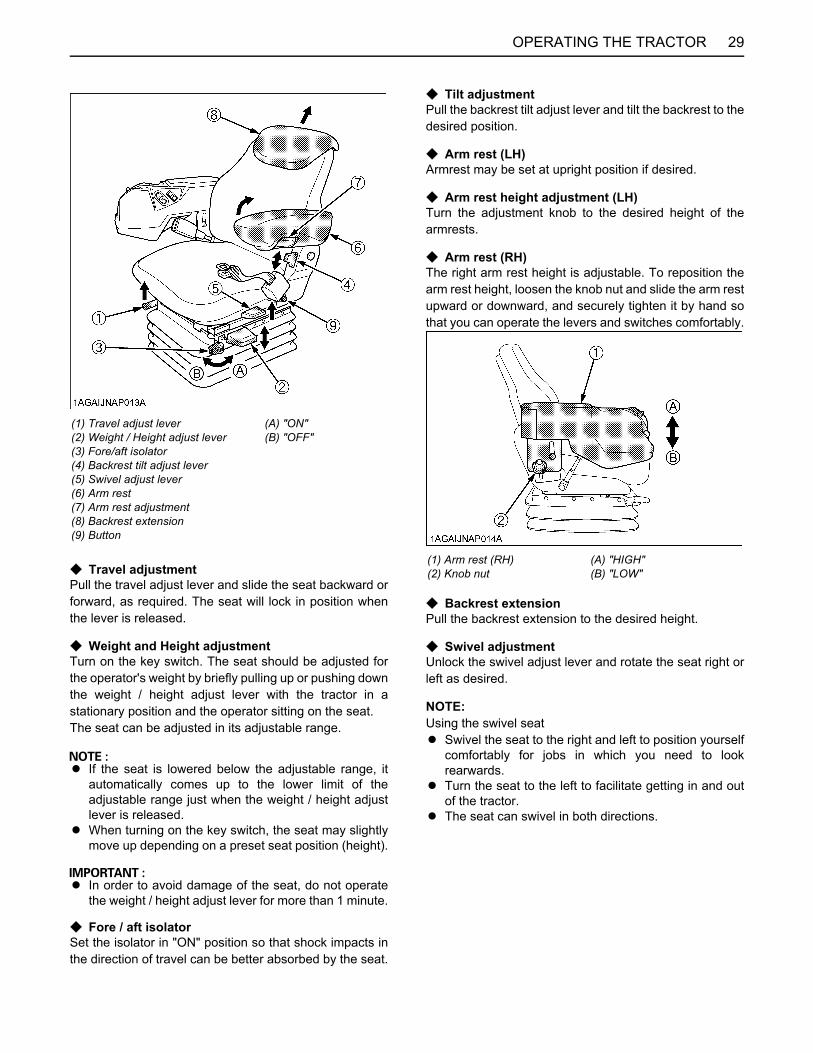
29OPERATING THE TRACTOR
C Travel adjustmentPull the travel adjust lever and slide the seat backward orforward, as required. The seat will lock in position whenthe lever is released.
C Weight and Height adjustmentTurn on the key switch. The seat should be adjusted forthe operator's weight by briefly pulling up or pushing downthe weight / height adjust lever with the tractor in astationary position and the operator sitting on the seat.The seat can be adjusted in its adjustable range.
A If the seat is lowered below the adjustable range, itautomatically comes up to the lower limit of theadjustable range just when the weight / height adjustlever is released.
A When turning on the key switch, the seat may slightlymove up depending on a preset seat position (height).
A In order to avoid damage of the seat, do not operatethe weight / height adjust lever for more than 1 minute.
C Fore / aft isolatorSet the isolator in "ON" position so that shock impacts inthe direction of travel can be better absorbed by the seat.
C Tilt adjustmentPull the backrest tilt adjust lever and tilt the backrest to thedesired position.
C Arm rest (LH)Armrest may be set at upright position if desired.
C Arm rest height adjustment (LH)Turn the adjustment knob to the desired height of thearmrests.
C Arm rest (RH)The right arm rest height is adjustable. To reposition thearm rest height, loosen the knob nut and slide the arm restupward or downward, and securely tighten it by hand sothat you can operate the levers and switches comfortably.
C Backrest extensionPull the backrest extension to the desired height.
C Swivel adjustmentUnlock the swivel adjust lever and rotate the seat right orleft as desired.
NOTE:Using the swivel seatA Swivel the seat to the right and left to position yourself
comfortably for jobs in which you need to lookrearwards.
A Turn the seat to the left to facilitate getting in and outof the tractor.
A The seat can swivel in both directions.
(1) Travel adjust lever(2) Weight / Height adjust lever(3) Fore/aft isolator(4) Backrest tilt adjust lever(5) Swivel adjust lever(6) Arm rest(7) Arm rest adjustment(8) Backrest extension(9) Button
(A) "ON"(B) "OFF"
(1) Arm rest (RH)(2) Knob nut
(A) "HIGH"(B) "LOW"
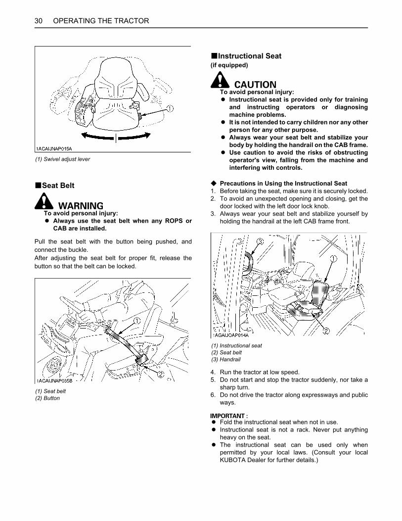
OPERATING THE TRACTOR30
BSeat Belt
To avoid personal injury:A Always use the seat belt when any ROPS or
CAB are installed.
Pull the seat belt with the button being pushed, andconnect the buckle.After adjusting the seat belt for proper fit, release thebutton so that the belt can be locked.
BInstructional Seat(if equipped)
To avoid personal injury:A Instructional seat is provided only for training
and instructing operators or diagnosingmachine problems.
A It is not intended to carry children nor any otherperson for any other purpose.
A Always wear your seat belt and stabilize yourbody by holding the handrail on the CAB frame.
A Use caution to avoid the risks of obstructingoperator's view, falling from the machine andinterfering with controls.
C Precautions in Using the Instructional Seat1. Before taking the seat, make sure it is securely locked.2. To avoid an unexpected opening and closing, get the
door locked with the left door lock knob.3. Always wear your seat belt and stabilize yourself by
holding the handrail at the left CAB frame front.
4. Run the tractor at low speed.5. Do not start and stop the tractor suddenly, nor take a
sharp turn.6. Do not drive the tractor along expressways and public
ways.
A Fold the instructional seat when not in use.A Instructional seat is not a rack. Never put anything
heavy on the seat.A The instructional seat can be used only when
permitted by your local laws. (Consult your localKUBOTA Dealer for further details.)
(1) Swivel adjust lever
(1) Seat belt(2) Button
(1) Instructional seat(2) Seat belt(3) Handrail

31OPERATING THE TRACTOR
BSteering Adjustment
To avoid personal injury:A Do not adjust the steering wheel while the
tractor is in motion.
Adjust the steering wheel to the best driving position usingtilt and telescope levers.
BExtendable Mirror1. To alter the length: Loosen the knob bolt and move the
mirror to the required position, then tighten the knobbolt.
2. To adjust mirror head: Hold firmly, tilt horizontally andvertically as required.
BLight Switch1. Turn the key to the "ON" position.2. Turn the switch knob clockwise, and the following
lights are activated on the knob position.
A High beam indicator will be on when head light switchis in "high beam" position.
BTurn Signal / Hazard Light SwitchC Hazard Light1. When the hazard light switch is pushed, the hazard
lights flash, along with the L/H and R/H indicators onthe instrument panel.
2. Push the hazard light switch again to turn off thehazard lights.
C Turn signal lightTo indicate a right turn, turn the turn signal light switchclockwise. To indicate a left turn, turn the turn signal lightswitch counter-clockwise. The corresponding right andleft turn signal lights and indicator on the instrument panelwill flash.
A The hazard light switch is operative when the keyswitch is in the "ON", "ACC" or "OFF" position.
A The turn signal light switch is only operative when thekey switch is in the "ON" position.
A Be sure to return the turn signal switch to centerposition after turning.
(1) Tilt lever(2) Telescope lever
(A) "UNLOCK"(B) "LOCK"
(1) Knob bolt
2. Selecting Light Switch Positions.
OFF...... Head lights OFF........ Head lights dimmed, low beam........ Head lights ON, high beam.
(1) Head light switch
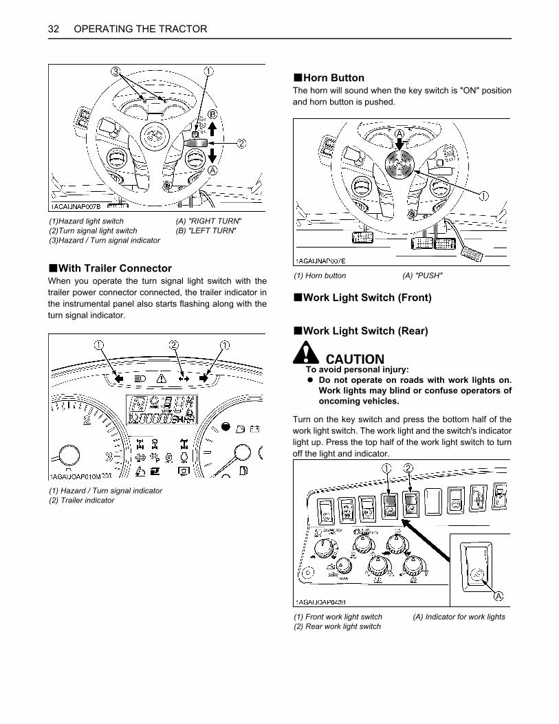
OPERATING THE TRACTOR32
BWith Trailer ConnectorWhen you operate the turn signal light switch with thetrailer power connector connected, the trailer indicator inthe instrumental panel also starts flashing along with theturn signal indicator.
BHorn ButtonThe horn will sound when the key switch is "ON" positionand horn button is pushed.
BWork Light Switch (Front)
BWork Light Switch (Rear)
To avoid personal injury:A Do not operate on roads with work lights on.
Work lights may blind or confuse operators ofoncoming vehicles.
Turn on the key switch and press the bottom half of thework light switch. The work light and the switch's indicatorlight up. Press the top half of the work light switch to turnoff the light and indicator.
(1)Hazard light switch(2)Turn signal light switch(3)Hazard / Turn signal indicator
(A) "RIGHT TURN"(B) "LEFT TURN"
(1) Hazard / Turn signal indicator(2) Trailer indicator
(1) Horn button (A) "PUSH"
(1) Front work light switch(2) Rear work light switch
(A) Indicator for work lights

33OPERATING THE TRACTOR
BBrake Pedals (Right and Left)
To avoid personal injury:A Be sure to interlock the right and left pedals.
Applying only one rear wheel brake at highspeeds could cause the tractor to swerve orroll-over.
A Be sure brake pedals have equal adjustmentwhen using locked together. Incorrect orunequal brake pedal adjustment can cause thetractor to swerve or roll-over.
To avoid personal injury:A Be aware of the enhanced braking
characteristics of 4 wheel braking system. Appropriate care should be taken during hardbraking and/or when pulling towed loads.
A Do not make sudden braking. An accident may occur such as by heavy towedload shifting forward or loss of control.
A To avoid skidding and less of steering controlwhen driving on icy, wet, or loose surfaces,make sure the tractor is correctly ballasted,operated at reduced speed, operated with frontwheel drive engaged (If equipped).
A The braking characteristics are differentbetween two and four wheel drive. Be aware ofthe difference and use carefully.
1. Before operating the tractor on the road, be sure tointerlock the right and left pedals as illustrated below.
2. Use individual brakes to assist in making sharp turnsat slow speeds (Field Operation Only). Disengage thebrake pedal lock and depress only one brake pedal.
3. Be sure brake pedals have equal adjustment whenbeing used locked together.
C 4WD Braking System [4WD model]4WD model tractor is equipped with 4WD braking system.When both brake pedals are applied together, the frontaxle is engaged for four wheel braking regardless of themode selected at the 4WD/Bi-speed turn switch. The4WD indicator light is not illuminated unless the front axleis engaged with the selector switch.
To avoid the possibility of personal injury orproperty damage from machine runaway duringtesting, service or repair with the rear wheels offthe ground, make sure:A Battery is disconnected and engine is not
started.If it is necessary to run the engine, make sure:A Both front and rear wheels are off the ground
and secured with stands before startingengine.
(1) Front work light (Hood)(2) Front work light(3) Rear work light
3. Checking the Brake Pedal.
(1) Brake pedal lock (A) "LOCK"(B) "RELEASE"
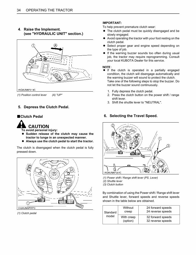
OPERATING THE TRACTOR34
BClutch Pedal
To avoid personal injury:A Sudden release of the clutch may cause the
tractor to lunge in an unexpected manner.A Always use the clutch pedal to start the tractor.
The clutch is disengaged when the clutch pedal is fullypressed down.
IMPORTANT:To help prevent premature clutch wear:A The clutch pedal must be quickly disengaged and be
slowly engaged.A Avoid operating the tractor with your foot resting on the
clutch pedal.A Select proper gear and engine speed depending on
the type of job.A If the warning buzzer sounds too often during usual
job, the tractor may require reprogramming. Consultyour local KUBOTA Dealer for this service.
A If the clutch is operated in a partially engagedcondition, the clutch will disengage automatically andthe warning buzzer will sound to protect the clutch.Take one of the following steps to stop the buzzer. Donot let the buzzer sound continuously.
By combination of using the Power shift / Range shift leverand Shuttle lever, forward speeds and reverse speedsshown in the table below are obtained.
4. Raise the Implement.(see "HYDRAULIC UNIT" section.)
(1) Position control lever (A) "UP"
5. Depress the Clutch Pedal.
(1) Clutch pedal
1. Fully depress the clutch pedal.2. Press the clutch button on the power shift / range
shift lever.3. Shift the shuttle lever to "NEUTRAL".
6. Selecting the Travel Speed.
(1) Power shift / Range shift lever (PS. Lever)(2) Shuttle lever(3) Clutch button
Standardmodel
Without creep
24 forward speeds24 reverse speeds
With creep(option)
32 forward speeds32 reverse speeds
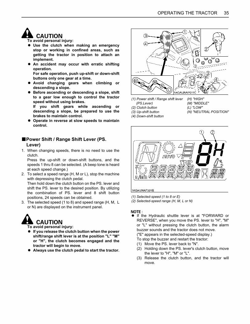
35OPERATING THE TRACTOR
To avoid personal injury:A Use the clutch when making an emergency
stop or working in confined areas, such asgetting the tractor in position to attach animplement.
A An accident may occur with erratic shiftingoperation.For safe operation, push up-shift or down-shiftbuttons only one gear at a time.
A Avoid changing gears when climbing ordescending a slope.
A Before ascending or descending a slope, shiftto a gear low enough to control the tractorspeed without using brakes.If you shift gears while ascending ordescending a slope, be prepared to use thebrakes to maintain control.
A Operate in reverse at slow speeds to maintaincontrol.
BPower Shift / Range Shift Lever (PS. Lever)
1. When changing speeds, there is no need to use theclutch.Press the up-shift or down-shift buttons, and thespeeds 1 thru 8 can be selected. (A beep tone is heardat each speed change.)
2. To select a speed range (H, M or L), stop the machinewith depressing the clutch pedal.Then hold down the clutch button on the PS. lever andshift the PS. lever to the desired position. By utilizingthe combination of PS. lever and 8 shift buttonpositions, 24 speeds can be obtained.
3. The selected speed (1 to 8) and speed range (H, M, Lor N) are displayed on the instrument panel.
To avoid personal injury:A If you release the clutch button when the power
shift/range shift lever is at the position "L" "M"or "H", the clutch becomes engaged and thetractor will begin to move.
A Always use the clutch pedal to start the tractor.
A If the Hydraulic shuttle lever is at "FORWARD orREVERSE", when you move the PS. lever to "H", "M"or "L" without pressing the clutch button, the alarmbuzzer sounds and the tractor does not move.("E" appears in the selected-speed display.)To stop the buzzer and restart the tractor:(1) Move the PS. lever back to "N".(2) Holding down the PS. lever's clutch button, move
the lever to "H", "M" or "L".(3) Release the clutch button, and the tractor will
move.
(1) Power shift / Range shift lever (PS.Lever)(2) Clutch button(3) Up-shift button(4) Down-shift button
(H) "HIGH"(M) "MIDDLE"(L) "LOW"(N) "NEUTRAL POSITION"
(1) Selected-speed (1 to 8 or E)(2) Selected-speed range (H, M, L or N)

OPERATING THE TRACTOR36
C Basic operation1. Start the engine, select a speed range "L", "M" or "H"
with the PS. lever, and the tractor is set at low speed(1), middle speed (1) [9th] or high speed (1) [17th]. ("1"appears on the display.)
2. With the PS. lever at "NEUTRAL", select a speed (1stto 8th) first using the button and then a speed range,the selected speed with button is obtained.
3. With the PS. lever at "NEUTRAL" and hold down thebutton, the speeds change themselves continuously.(1st to 8th or 8th to 1st)
4. With a speed range "L", "M" or "H" selected,depressing the button changes the speeds. If theshuttle lever is set at "NEUTRAL" or the clutch pedalstays "DISENGAGED", however, the speeds changethemselves continuously. (1st to 8th or 8th to 1st)
5. Main gear shift speed memory function:Suppose that a job was done at a travel speed, thespeed range (L, M, H) was changed and then theoriginal speed range was returned. The memoryfunction serves to automatically pick up the previouslyselected main gear number.Only when the speed range is “H” and the main gearshift is somewhere between Speed 4 (20th) andSpeed 8 (24th), however, the “H-3” speed (19th) isautomatically selected.
A Memorized speed
A Turn off the key switch, and the memory will becleared.
A Before selecting a speed range, be sure to stop thetractor. Step on the brake pedal and shift the PS. leverslowly.
A When you have shifted the PS. lever to "L", "M" or "H"range, be sure to look at the indicator for the powershift position. Then release the clutch button or theclutch pedal.
A Start in lower gears and shift one gear at a time untildesired gear is obtained.
A To prolong clutch life, avoid slipping the hydraulicclutch. Pay attention to the following points:A Select proper gear and engine speed depending
on the type of job.A Avoid lugging the engine, especially in higher
gears. If RPM's drop excessively, shift to a lowergear.
A In cold climate, it may take longer for the tractor tomove after the PS.lever is moved. This is because thetransmission oil must warm up.A Properly warm up the machine. If there is not
enough time to do so, start the machine with theclutch pedal slowly.
A There is no problem with a delay in starting.The machine will start as the oil temperatureincreases.
BDHC switchOn this tractor, the engine load and other fluctuations aresensed and the speed is well controlled in response to theloads. Turn the DHC switch "ON" when using a tractionPTO attachment (baler, etc.) on a slope. A well responsivespeed control can be expected. In other applications, turnthis switch "OFF". Smooth speed change is available forcomfortable ride.
Power shift / Range shift lever
L1~8(1st to 8th) Shift up
H1~8(17th to 24th)M1~8(9th to 16th)
Shift down
L1~8(1st to 8th)
M1~8(9th to 16th) Shift up
H1~8(17th to 24th) Shift down
M1~8(9th to 16th)
M1~8(9th to 16th) Shift down
L1~8(1st to 8th) Shift up
M1~8(9th to 16th)
H1~3(17th to 19th)
Shift down
L1~8(1st to 8th) Shift up
H1~3(17th to 19th)
H4~8(20th to 24th)
H3(19th)
H1~3(17th to 19th)
Shift down
M1~8(9th to 16th) Shift up
H1~3(17th to 19th)
H4~8(20th to 24th)
H3(19th) (1) DHC switch (A) "Push to ON"
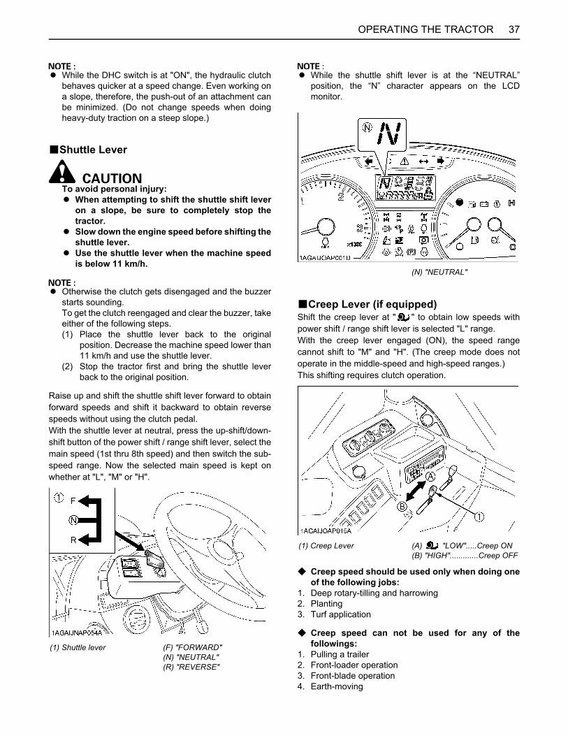
37OPERATING THE TRACTOR
A While the DHC switch is at "ON", the hydraulic clutchbehaves quicker at a speed change. Even working ona slope, therefore, the push-out of an attachment canbe minimized. (Do not change speeds when doingheavy-duty traction on a steep slope.)
BShuttle Lever
To avoid personal injury:A When attempting to shift the shuttle shift lever
on a slope, be sure to completely stop thetractor.
A Slow down the engine speed before shifting theshuttle lever.
A Use the shuttle lever when the machine speedis below 11 km/h.
A Otherwise the clutch gets disengaged and the buzzerstarts sounding.To get the clutch reengaged and clear the buzzer, takeeither of the following steps.(1) Place the shuttle lever back to the original
position. Decrease the machine speed lower than11 km/h and use the shuttle lever.
(2) Stop the tractor first and bring the shuttle leverback to the original position.
Raise up and shift the shuttle shift lever forward to obtainforward speeds and shift it backward to obtain reversespeeds without using the clutch pedal.With the shuttle lever at neutral, press the up-shift/down-shift button of the power shift / range shift lever, select themain speed (1st thru 8th speed) and then switch the sub-speed range. Now the selected main speed is kept onwhether at "L", "M" or "H".
A While the shuttle shift lever is at the “NEUTRAL”position, the “N” character appears on the LCDmonitor.
BCreep Lever (if equipped)Shift the creep lever at " " to obtain low speeds withpower shift / range shift lever is selected "L" range.With the creep lever engaged (ON), the speed rangecannot shift to "M" and "H". (The creep mode does notoperate in the middle-speed and high-speed ranges.)This shifting requires clutch operation.
C Creep speed should be used only when doing oneof the following jobs:
1. Deep rotary-tilling and harrowing2. Planting3. Turf application
C Creep speed can not be used for any of thefollowings:
1. Pulling a trailer2. Front-loader operation3. Front-blade operation4. Earth-moving
(1) Shuttle lever (F) "FORWARD"(N) "NEUTRAL"(R) "REVERSE"
(N) "NEUTRAL"
(1) Creep Lever (A) "LOW".....Creep ON(B) "HIGH".............Creep OFF
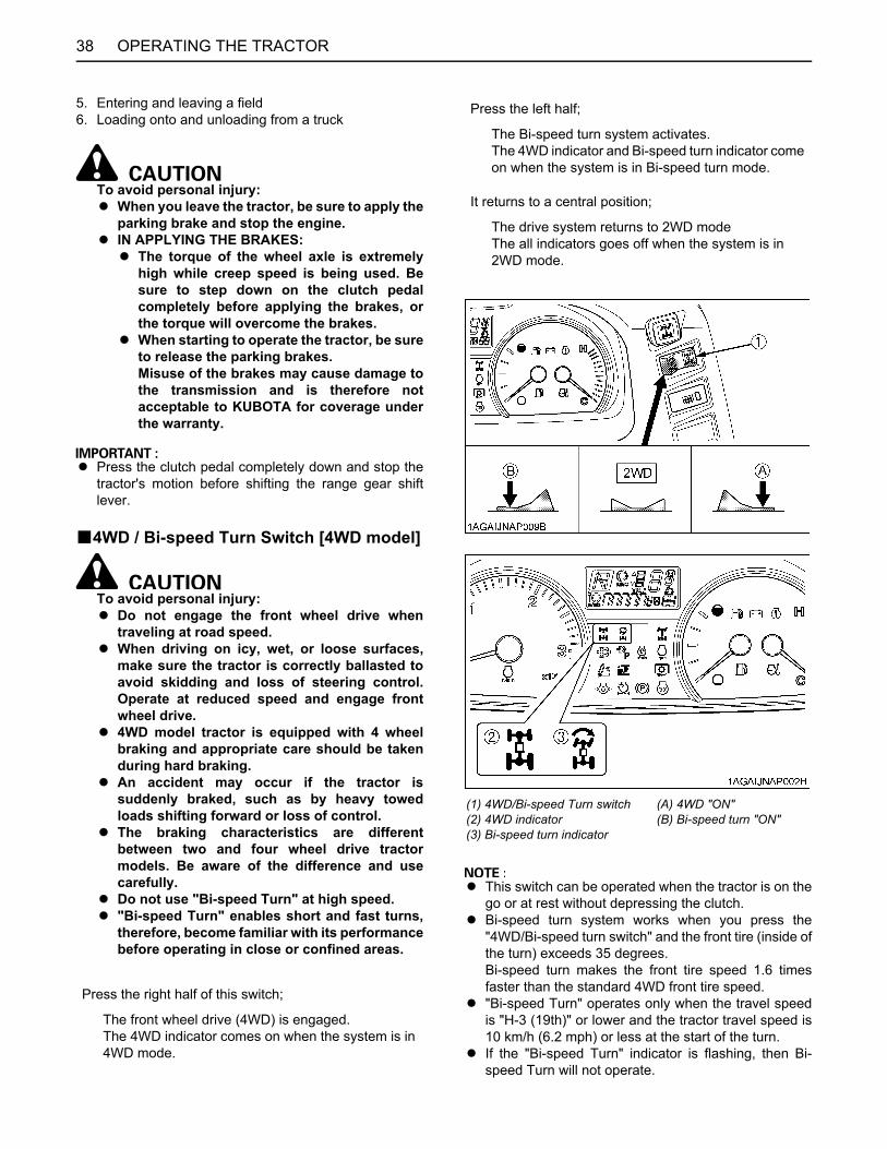
OPERATING THE TRACTOR38
5. Entering and leaving a field6. Loading onto and unloading from a truck
To avoid personal injury:A When you leave the tractor, be sure to apply the
parking brake and stop the engine.A IN APPLYING THE BRAKES:
A The torque of the wheel axle is extremelyhigh while creep speed is being used. Besure to step down on the clutch pedalcompletely before applying the brakes, orthe torque will overcome the brakes.
A When starting to operate the tractor, be sureto release the parking brakes.Misuse of the brakes may cause damage tothe transmission and is therefore notacceptable to KUBOTA for coverage underthe warranty.
A Press the clutch pedal completely down and stop thetractor's motion before shifting the range gear shiftlever.
B4WD / Bi-speed Turn Switch [4WD model]
To avoid personal injury:A Do not engage the front wheel drive when
traveling at road speed.A When driving on icy, wet, or loose surfaces,
make sure the tractor is correctly ballasted toavoid skidding and loss of steering control.Operate at reduced speed and engage frontwheel drive.
A 4WD model tractor is equipped with 4 wheelbraking and appropriate care should be takenduring hard braking.
A An accident may occur if the tractor issuddenly braked, such as by heavy towedloads shifting forward or loss of control.
A The braking characteristics are differentbetween two and four wheel drive tractormodels. Be aware of the difference and usecarefully.
A Do not use "Bi-speed Turn" at high speed.A "Bi-speed Turn" enables short and fast turns,
therefore, become familiar with its performancebefore operating in close or confined areas.
A This switch can be operated when the tractor is on thego or at rest without depressing the clutch.
A Bi-speed turn system works when you press the"4WD/Bi-speed turn switch" and the front tire (inside ofthe turn) exceeds 35 degrees.Bi-speed turn makes the front tire speed 1.6 timesfaster than the standard 4WD front tire speed.
A "Bi-speed Turn" operates only when the travel speedis "H-3 (19th)" or lower and the tractor travel speed is10 km/h (6.2 mph) or less at the start of the turn.
A If the "Bi-speed Turn" indicator is flashing, then Bi-speed Turn will not operate.
Press the right half of this switch;
The front wheel drive (4WD) is engaged.The 4WD indicator comes on when the system is in 4WD mode.
Press the left half;
The Bi-speed turn system activates.The 4WD indicator and Bi-speed turn indicator come on when the system is in Bi-speed turn mode.
It returns to a central position;
The drive system returns to 2WD modeThe all indicators goes off when the system is in 2WD mode.
(1) 4WD/Bi-speed Turn switch(2) 4WD indicator(3) Bi-speed turn indicator
(A) 4WD "ON"(B) Bi-speed turn "ON"
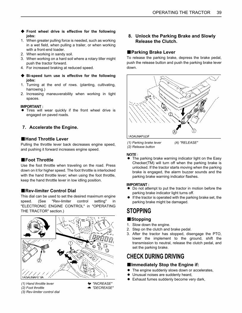
39OPERATING THE TRACTOR
C Front wheel drive is effective for the followingjobs:
1. When greater pulling force is needed, such as workingin a wet field, when pulling a trailer, or when workingwith a front-end loader.
2. When working in sandy soil.3. When working on a hard soil where a rotary tiller might
push the tractor forward.4. For increased braking at reduced speed.
C Bi-speed turn use is effective for the followingjobs:
1. Turning at the end of rows. (planting, cultivating,harrowing.)
2. Increasing maneuverability when working in tightspaces.
A Tires will wear quickly if the front wheel drive isengaged on paved roads.
BHand Throttle LeverPulling the throttle lever back decreases engine speed,and pushing it forward increases engine speed.
BFoot ThrottleUse the foot throttle when traveling on the road. Pressdown on it for higher speed. The foot throttle is interlockedwith the hand throttle lever; when using the foot throttle,keep the hand throttle lever in low idling position.
BRev-limiter Control DialThis dial can be used to set the desired maximum enginespeed. (See "Rev-limiter control setting" in"ELECTRONIC ENGINE CONTROL" in "OPERATINGTHE TRACTOR" section.)
BParking Brake LeverTo release the parking brake, depress the brake pedal,push the release button and push the parking brake leverdown.
A The parking brake warning indicator light on the EasyChecker(TM) will turn off when the parking brake isunlocked. If the tractor starts moving when the parkingbrake is engaged, the alarm buzzer sounds and theparking brake warning indicator flashes.
A Do not attempt to put the tractor in motion before theparking brake indicator light turns off.
A If the tractor is operated with the parking brake set, theparking brake might be damaged.
STOPPINGBStopping1. Slow down the engine.2. Step on the clutch and brake pedal.3. After the tractor has stopped, disengage the PTO,
lower the implement to the ground, shift thetransmission to neutral, release the clutch pedal, andset the parking brake.
CHECK DURING DRIVINGBImmediately Stop the Engine if:A The engine suddenly slows down or accelerates,A Unusual noises are suddenly heard,A Exhaust fumes suddenly become very dark,
7. Accelerate the Engine.
(1) Hand throttle lever(2) Foot throttle(3) Rev-limiter control dial
"INCREASE" "DECREASE"
8. Unlock the Parking Brake and Slowly Release the Clutch.
(1) Parking brake lever(2) Release button
(A) "RELEASE"
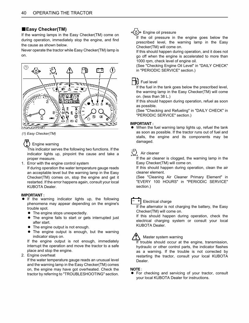
OPERATING THE TRACTOR40
BEasy Checker(TM)If the warning lamps in the Easy Checker(TM) come onduring operation, immediately stop the engine, and findthe cause as shown below.Never operate the tractor while Easy Checker(TM) lamp ison.
Engine warningThis indicator serves the following two functions. If theindicator lights up, pinpoint the cause and take aproper measure.
1. Error with the engine control systemIf during operation the water temperature gauge readsan acceptable level but the warning lamp in the EasyChecker(TM) comes on, stop the engine and get itrestarted. If the error happens again, consult your localKUBOTA Dealer.
A If the warning indicator lights up, the followingphenomena may appear depending on the engine'strouble spot.A The engine stops unexpectedly.A The engine fails to start or gets interrupted just
after start.A The engine output is not enough.A The engine output is enough, but the warning
indicator stays on.If the engine output is not enough, immediatelyinterrupt the operation and move the tractor to a safeplace and stop the engine.
2. Engine overheatIf the water temperature gauge reads an unusual leveland the warning lamp in the Easy Checker(TM) comeson, the engine may have got overheated. Check thetractor by referring to "TROUBLESHOOTING" section.
Engine oil pressureIf the oil pressure in the engine goes below theprescribed level, the warning lamp in the EasyChecker(TM) will come on.If this should happen during operation, and it does notgo off when the engine is accelerated to more than1000 rpm, check level of engine oil.(See "Checking Engine Oil Level" in "DAILY CHECK"in "PERIODIC SERVICE" section.)
Fuel levelIf the fuel in the tank goes below the prescribed level,the warning lamp in the Easy Checker(TM) will comeon. (less than 38 L.)If this should happen during operation, refuel as soonas possible.(See "Checking and Refueling" in "DAILY CHECK" in"PERIODIC SERVICE" section.)
A When the fuel warning lamp lights up, refuel the tankas soon as possible. If the tractor runs out of fuel andstalls, the engine and its components may bedamaged.
Air cleanerIf the air cleaner is clogged, the warning lamp in theEasy Checker(TM) will come on.If this should happen during operation, clean the aircleaner element.(See "Cleaning Air Cleaner Primary Element" in"EVERY 100 HOURS" in "PERIODIC SERVICE"section.)
Electrical chargeIf the alternator is not charging the battery, the EasyChecker(TM) will come on.If this should happen during operation, check theelectrical charging system or consult your localKUBOTA Dealer.
Master system warningIf trouble should occur at the engine, transmission,hydraulic or other control parts, the indicator flashesas a warning. If the trouble is not corrected byrestarting the tractor, consult your local KUBOTADealer.
A For checking and servicing of your tractor, consultyour local KUBOTA Dealer for instructions.
(1) Easy Checker(TM)
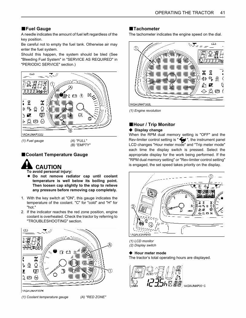
41OPERATING THE TRACTOR
BFuel GaugeA needle indicates the amount of fuel left regardless of thekey position.Be careful not to empty the fuel tank. Otherwise air mayenter the fuel system.Should this happen, the system should be bled (See"Bleeding Fuel System" in "SERVICE AS REQUIRED" in"PERIODIC SERVICE" section.)
BCoolant Temperature Gauge
To avoid personal injury:A Do not remove radiator cap until coolant
temperature is well below its boiling point.Then loosen cap slightly to the stop to relieveany pressure before removing cap completely.
1. With the key switch at "ON", this gauge indicates thetemperature of the coolant. "C" for "cold" and "H" for"hot."
2. If the indicator reaches the red zone position, enginecoolant is overheated. Check the tractor by referring to"TROUBLESHOOTING" section.
BTachometerThe tachometer indicates the engine speed on the dial.
BHour / Trip MonitorC Display changeWhen the RPM dual memory setting is "OFF" and theRev-limiter control setting is " ", the instrument panelLCD changes "Hour meter mode" and "Trip meter mode"each time the display switch is pressed. Select theappropriate display for the work being performed. If the"RPM dual memory setting" or "Rev-limiter control setting"is engaged, the set speed takes priority on the display.
C Hour meter modeThe tractor’s total operating hours are displayed.
(1) Fuel gauge (A) "FULL"(B) "EMPTY"
(1) Coolant temperature gauge (A) "RED ZONE"
(1) Engine revolution
(1) LCD monitor(2) Display switch

OPERATING THE TRACTOR42
C Trip meter modeThe total operating hours counted from the previousresetting is displayed.Hold down the display switch for 2 seconds or longer toreset the trip meter to [0. 0].
C Priority displayIf the "RPM dual memory setting" or "Rev-limiter controlsetting" is engaged, the set speed takes priority on thedisplay. The figure shown below is an example of thedisplay when the engine speed has been set for the switchA side.
SIDE DIGITAL DISPLAYThis display shows the following information.1. Four rows with 30 types of tractor information, such as
travel speed, PTO rpm and mileage can be selectedby the operator.
2. Operating history for the past 4 months can bedisplayed.
This chapter covers "How to view and select" the 4 rowsof information.For the meanings and selection procedures of other data,as well as changing the display settings, refer to the "SIDEDIGITAL DISPLAY" appendices at the back of thismanual.
BInitial SettingBefore use, make sure the tire circumference installed,the clock and the working range of implement are set.Otherwise, the travel speed, work area, work distance andother data will not be correctly displayed.
C Setting procedure1. Turn on the key switch. With the following data on the
screen, hold down the mode selector switch. Variousscreens can be selected.
2. Select the tire circumference setting mode with Switch3 and press Switch 4 to go to the tire circumferencesetting screen.
3. Check to see if the tire circumference is correctlypreset. If not, correct the numerical settings withSwitches 1, 2 and 3, referring to the table below. PressSwitch 4 to save the new setting.
4. Select the tire circumference setting mode with Switch3 and press Switch 4 to go to the tire circumferencesetting screen.
(1) Switch A(2) Set engine speed
(1) Mode selector switch
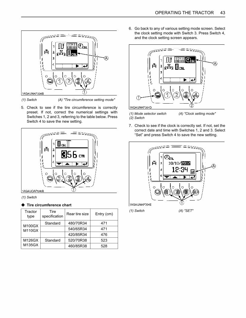
43OPERATING THE TRACTOR
5. Check to see if the tire circumference is correctlypreset. If not, correct the numerical settings withSwitches 1, 2 and 3, referring to the table below. PressSwitch 4 to save the new setting.
C Tire circumference chart
6. Go back to any of various setting mode screen. Selectthe clock setting mode with Switch 3. Press Switch 4,and the clock setting screen appears.
7. Check to see if the clock is correctly set. If not, set thecorrect date and time with Switches 1, 2 and 3. Select“Set” and press Switch 4 to save the new setting.
(1) Switch (A) "Tire circumference setting mode"
(1) Switch
Tractor type
Tire specification Rear tire size Entry (cm)
M100GXM110GX
Standard 480/70R34 471540/65R34 471420/85R34 476
M126GXM135GX
Standard 520/70R38 523460/85R38 528
(1) Mode selector switch(2) Switch
(A) "Clock setting mode"
(1) Switch (A) "SET"
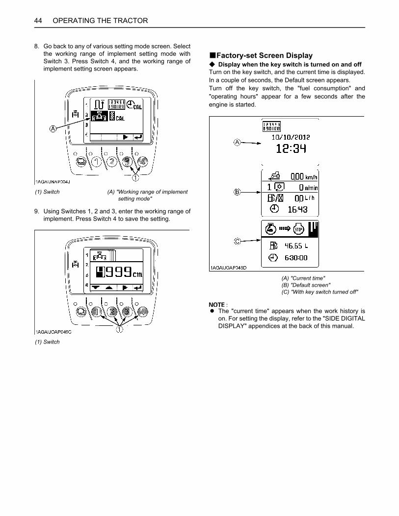
OPERATING THE TRACTOR44
8. Go back to any of various setting mode screen. Selectthe working range of implement setting mode withSwitch 3. Press Switch 4, and the working range ofimplement setting screen appears.
9. Using Switches 1, 2 and 3, enter the working range ofimplement. Press Switch 4 to save the setting.
BFactory-set Screen DisplayC Display when the key switch is turned on and offTurn on the key switch, and the current time is displayed.In a couple of seconds, the Default screen appears.Turn off the key switch, the "fuel consumption" and"operating hours" appear for a few seconds after theengine is started.
A The "current time" appears when the work history ison. For setting the display, refer to the "SIDE DIGITALDISPLAY" appendices at the back of this manual.
(1) Switch (A) "Working range of implement setting mode"
(1) Switch
(A) "Current time"(B) "Default screen"(C) "With key switch turned off"

45OPERATING THE TRACTOR
C Display Operating ProceduresThe display has been factory-set for the following 4settings. They are interlocked from top to bottom withSwitches 1 thru 4. For viewing and modifying theinformation, see the chart on the next page.
Indicator
(1) Switch(2) Indicator
ON Press the switch to change the display.
OFF The display does not change even bypressing the switch.
FLASHING The data are reset by holding down theswitch.
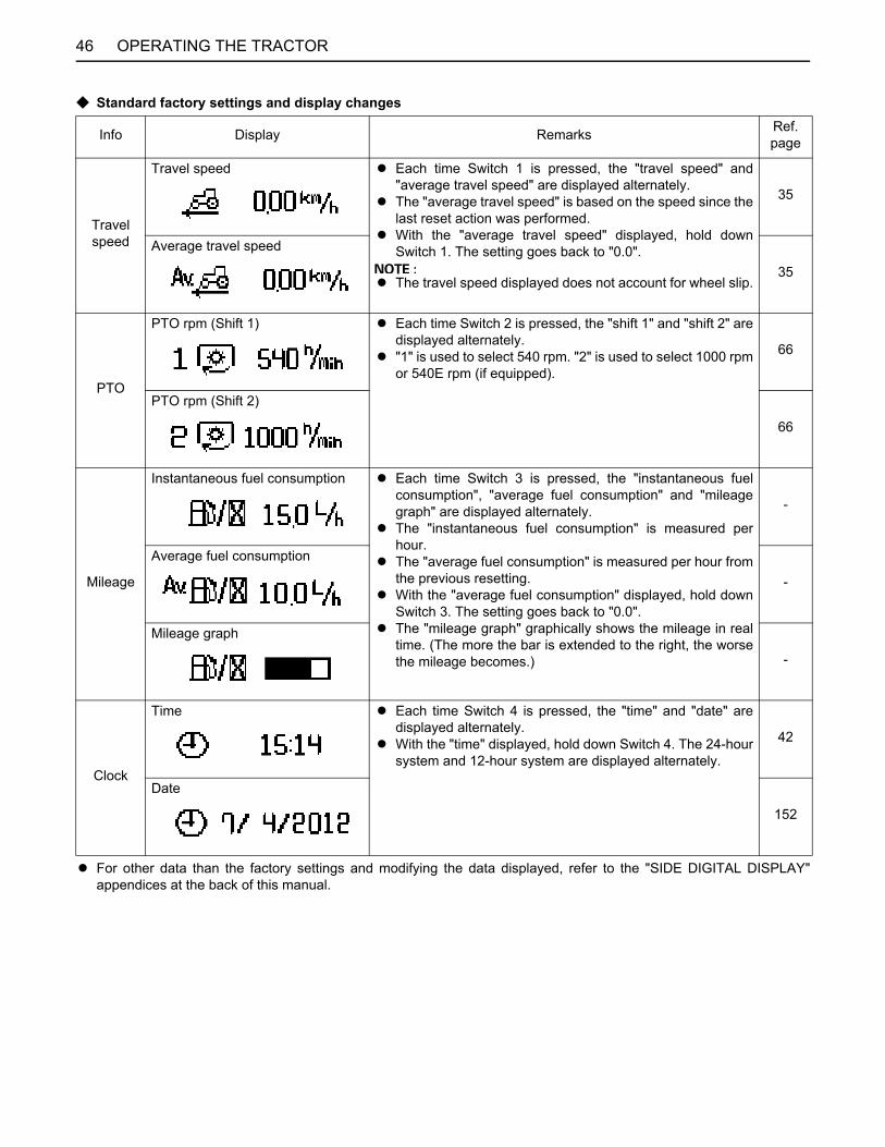
OPERATING THE TRACTOR46
C Standard factory settings and display changes
A For other data than the factory settings and modifying the data displayed, refer to the "SIDE DIGITAL DISPLAY"appendices at the back of this manual.
Info Display Remarks Ref. page
Travel speed
Travel speed A Each time Switch 1 is pressed, the "travel speed" and"average travel speed" are displayed alternately.
A The "average travel speed" is based on the speed since thelast reset action was performed.
A With the "average travel speed" displayed, hold downSwitch 1. The setting goes back to "0.0".
A The travel speed displayed does not account for wheel slip.
35
Average travel speed
35
PTO
PTO rpm (Shift 1) A Each time Switch 2 is pressed, the "shift 1" and "shift 2" aredisplayed alternately.
A "1" is used to select 540 rpm. "2" is used to select 1000 rpmor 540E rpm (if equipped).
66
PTO rpm (Shift 2)
66
Mileage
Instantaneous fuel consumption A Each time Switch 3 is pressed, the "instantaneous fuelconsumption", "average fuel consumption" and "mileagegraph" are displayed alternately.
A The "instantaneous fuel consumption" is measured perhour.
A The "average fuel consumption" is measured per hour fromthe previous resetting.
A With the "average fuel consumption" displayed, hold downSwitch 3. The setting goes back to "0.0".
A The "mileage graph" graphically shows the mileage in realtime. (The more the bar is extended to the right, the worsethe mileage becomes.)
-
Average fuel consumption
-
Mileage graph
-
Clock
Time A Each time Switch 4 is pressed, the "time" and "date" aredisplayed alternately.
A With the "time" displayed, hold down Switch 4. The 24-hoursystem and 12-hour system are displayed alternately.
42
Date
152
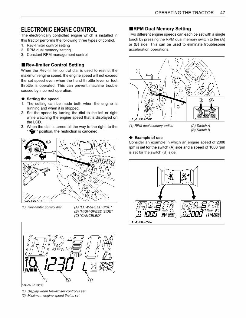
47OPERATING THE TRACTOR
ELECTRONIC ENGINE CONTROLThe electronically controlled engine which is installed inthis tractor performs the following three types of control.1. Rev-limiter control setting2. RPM dual memory setting3. Constant RPM management control
BRev-limiter Control SettingWhen the Rev-limiter control dial is used to restrict themaximum engine speed, the engine speed will not exceedthe set speed even when the hand throttle lever or footthrottle is operated. This can prevent machine troublecaused by incorrect operation.
C Setting the speed1. The setting can be made both when the engine is
running and when it is stopped.2. Set the speed by turning the dial to the left or right
while watching the engine speed that is displayed onthe LCD.
3. When the dial is turned all the way to the right, to the" " position, the restriction is canceled.
BRPM Dual Memory SettingTwo different engine speeds can each be set with a singletouch by pressing the RPM dual memory switch to the (A)or (B) side. This can be used to eliminate troublesomeacceleration operations.
C Example of useConsider an example in which an engine speed of 2000rpm is set for the switch (A) side and a speed of 1000 rpmis set for the switch (B) side.
(1) Rev-limiter control dial (A) "LOW-SPEED SIDE"(B) "HIGH-SPEED SIDE"(C) "CANCELED"
(1)(2)
Display when Rev-limiter control is setMaximum engine speed that is set
(1) RPM dual memory switch (A) Switch A(B) Switch B
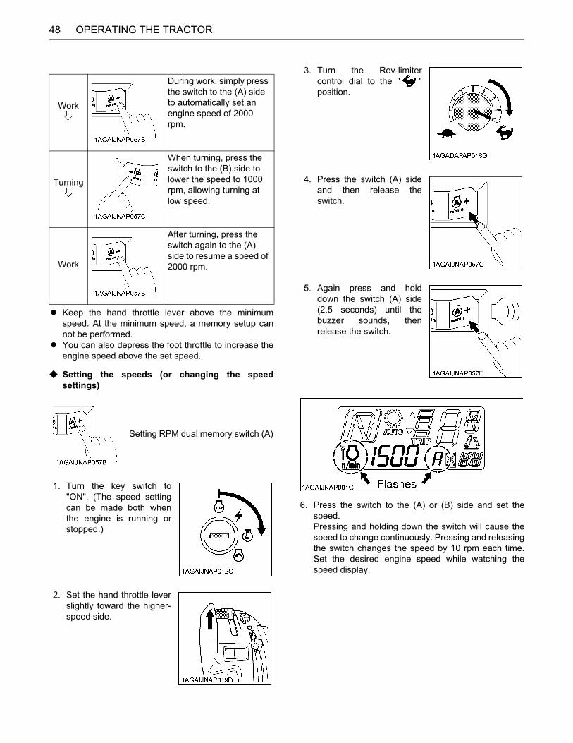
OPERATING THE TRACTOR48
A Keep the hand throttle lever above the minimumspeed. At the minimum speed, a memory setup cannot be performed.
A You can also depress the foot throttle to increase theengine speed above the set speed.
C Setting the speeds (or changing the speedsettings)
6. Press the switch to the (A) or (B) side and set thespeed.Pressing and holding down the switch will cause thespeed to change continuously. Pressing and releasingthe switch changes the speed by 10 rpm each time.Set the desired engine speed while watching thespeed display.
Work
During work, simply press the switch to the (A) side to automatically set an engine speed of 2000 rpm.
Turning
When turning, press the switch to the (B) side to lower the speed to 1000 rpm, allowing turning at low speed.
Work
After turning, press the switch again to the (A) side to resume a speed of 2000 rpm.
Setting RPM dual memory switch (A)
1. Turn the key switch to"ON". (The speed settingcan be made both whenthe engine is running orstopped.)
2. Set the hand throttle leverslightly toward the higher-speed side.
3. Turn the Rev-limitercontrol dial to the " "position.
4. Press the switch (A) sideand then release theswitch.
5. Again press and holddown the switch (A) side(2.5 seconds) until thebuzzer sounds, thenrelease the switch.
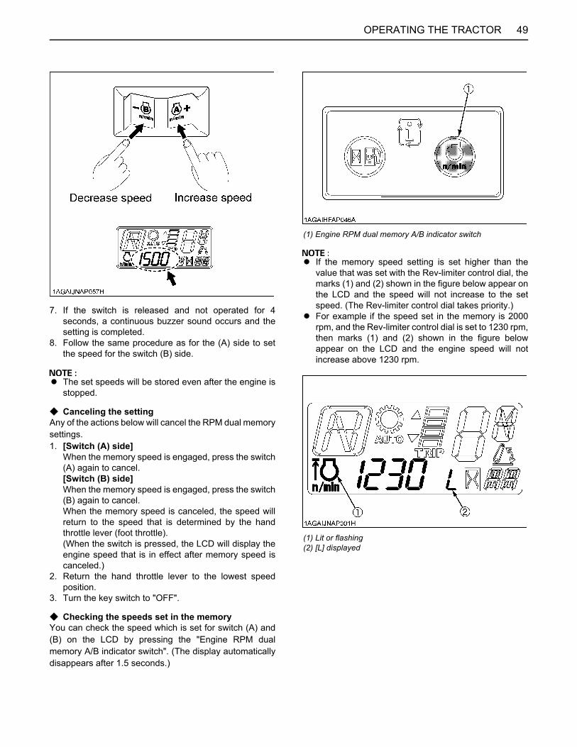
49OPERATING THE TRACTOR
7. If the switch is released and not operated for 4seconds, a continuous buzzer sound occurs and thesetting is completed.
8. Follow the same procedure as for the (A) side to setthe speed for the switch (B) side.
A The set speeds will be stored even after the engine isstopped.
C Canceling the settingAny of the actions below will cancel the RPM dual memorysettings.1. [Switch (A) side]
When the memory speed is engaged, press the switch(A) again to cancel.[Switch (B) side]When the memory speed is engaged, press the switch(B) again to cancel.When the memory speed is canceled, the speed willreturn to the speed that is determined by the handthrottle lever (foot throttle).(When the switch is pressed, the LCD will display theengine speed that is in effect after memory speed iscanceled.)
2. Return the hand throttle lever to the lowest speedposition.
3. Turn the key switch to "OFF".
C Checking the speeds set in the memory You can check the speed which is set for switch (A) and(B) on the LCD by pressing the "Engine RPM dualmemory A/B indicator switch". (The display automaticallydisappears after 1.5 seconds.)
A If the memory speed setting is set higher than thevalue that was set with the Rev-limiter control dial, themarks (1) and (2) shown in the figure below appear onthe LCD and the speed will not increase to the setspeed. (The Rev-limiter control dial takes priority.)
A For example if the speed set in the memory is 2000rpm, and the Rev-limiter control dial is set to 1230 rpm,then marks (1) and (2) shown in the figure belowappear on the LCD and the engine speed will notincrease above 1230 rpm.
(1) Engine RPM dual memory A/B indicator switch
(1) Lit or flashing(2) [L] displayed

OPERATING THE TRACTOR50
BConstant RPM Management ControlConstant RPM Management can be turned "ON" or "OFF"by operating the switch. Pressing the switch to the lowerside turns the control "ON" and pressing the switch to theupper side turns it "OFF".
C When constant RPM management is "ON"Fluctuations in the engine speed due to load fluctuationsare reduced and the travel speed and PTO speed are keptnearly constant, allowing stable work. When constantRPM management is "ON", the switch and the instrumentpanel indicator light up.
C When constant RPM management is "OFFAs in a conventional engine, the engine speed increasesor decreases according to changes in the load. Theoperator judges the size of the load from the engine speedand engine sound, and can adjust the travel speed orplowing depth to prevent overload on the tractor.
A In a mechanically-controlled engine, the engine speedchanges according to increases and decreases in theload.For example, when working in a hilly area, the loadincreases and engine speed drops while ascending aslope, and conversely the load drops whendescending. These changes in engine speed affectthe travel speed and PTO-driven implements. In orderto minimize these effects, the operator must make fineadjustments to the travel speed and hand throttlelever.When the constant RPM management switch in thistractor with its electronically controlled engine isturned "ON", the engine speed will be kept nearlyconstant in response to a certain level of loadfluctuations. This improves the accuracy of workwithout the need for troublesome manipulation of thetravel speed and hand throttle lever.
A It is recommended that a combination of light-loadPTO-driven implements and AUTO-MODE (Automaticspeed change) be used.
A There is a limit to the range within which a constantspeed can be maintained. If a load exceeding theengine performance is applied, the engine speed willdrop.
A The purpose of constant RPM management is not toincrease the engine power.
(1) Constant RPM management switch (A) "PRESS (ON)"
(1) Constant RPM management indicator
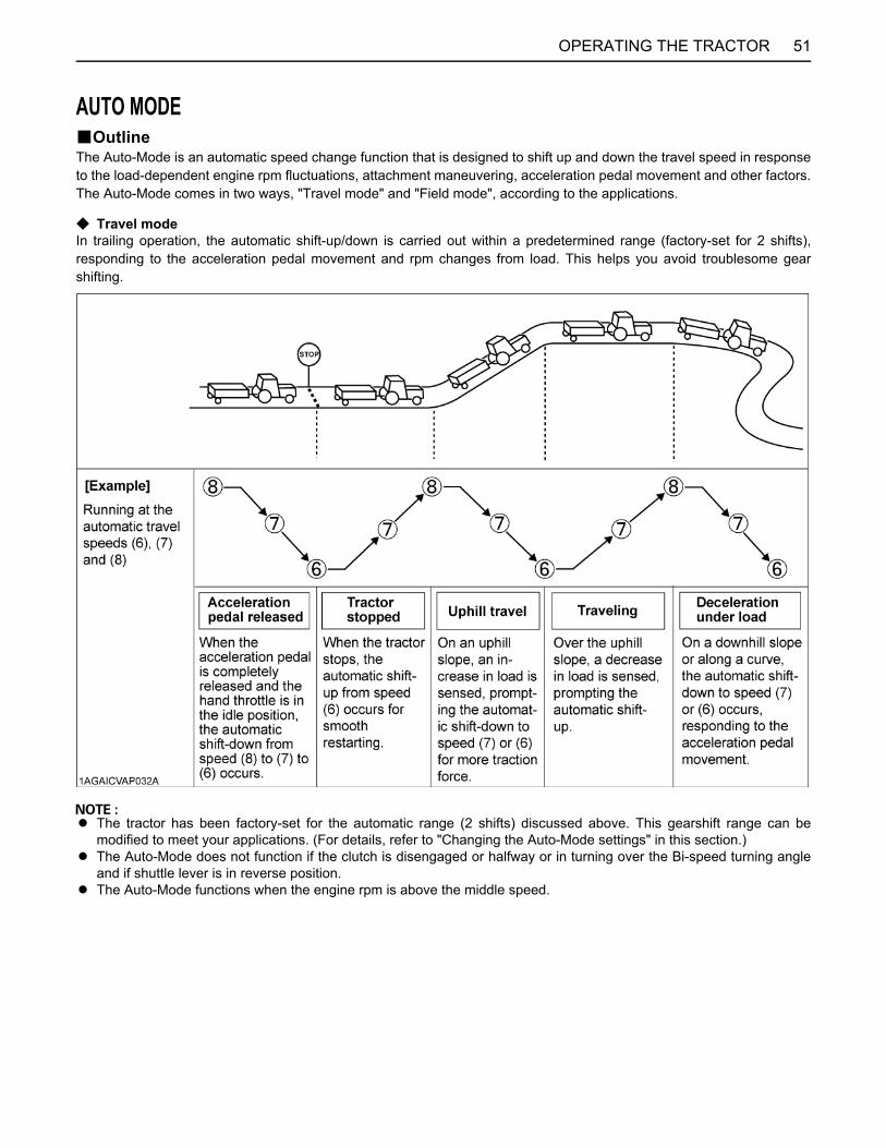
51OPERATING THE TRACTOR
AUTO MODEBOutlineThe Auto-Mode is an automatic speed change function that is designed to shift up and down the travel speed in responseto the load-dependent engine rpm fluctuations, attachment maneuvering, acceleration pedal movement and other factors.The Auto-Mode comes in two ways, "Travel mode" and "Field mode", according to the applications.
C Travel modeIn trailing operation, the automatic shift-up/down is carried out within a predetermined range (factory-set for 2 shifts),responding to the acceleration pedal movement and rpm changes from load. This helps you avoid troublesome gearshifting.
A The tractor has been factory-set for the automatic range (2 shifts) discussed above. This gearshift range can bemodified to meet your applications. (For details, refer to "Changing the Auto-Mode settings" in this section.)
A The Auto-Mode does not function if the clutch is disengaged or halfway or in turning over the Bi-speed turning angleand if shuttle lever is in reverse position.
A The Auto-Mode functions when the engine rpm is above the middle speed.
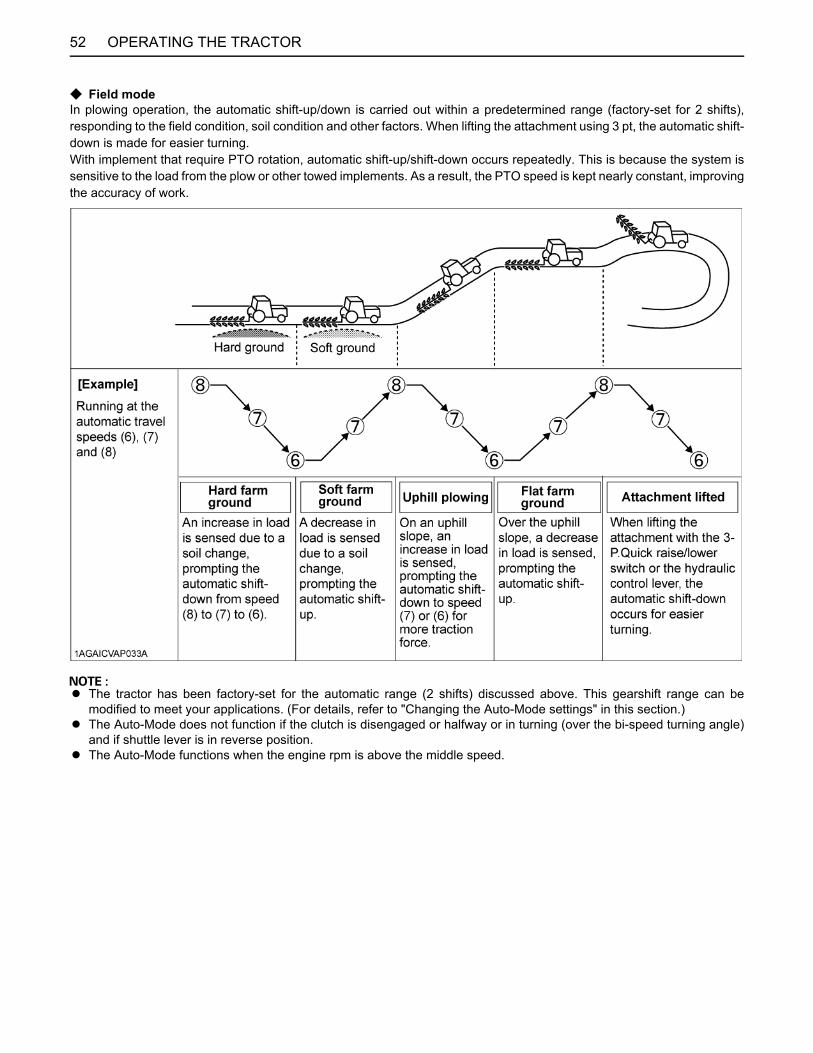
52 OPERATING THE TRACTOR
C Field modeIn plowing operation, the automatic shift-up/down is carried out within a predetermined range (factory-set for 2 shifts),responding to the field condition, soil condition and other factors. When lifting the attachment using 3 pt, the automatic shift-down is made for easier turning.With implement that require PTO rotation, automatic shift-up/shift-down occurs repeatedly. This is because the system issensitive to the load from the plow or other towed implements. As a result, the PTO speed is kept nearly constant, improvingthe accuracy of work.
A The tractor has been factory-set for the automatic range (2 shifts) discussed above. This gearshift range can bemodified to meet your applications. (For details, refer to "Changing the Auto-Mode settings" in this section.)
A The Auto-Mode does not function if the clutch is disengaged or halfway or in turning (over the bi-speed turning angle)and if shuttle lever is in reverse position.
A The Auto-Mode functions when the engine rpm is above the middle speed.
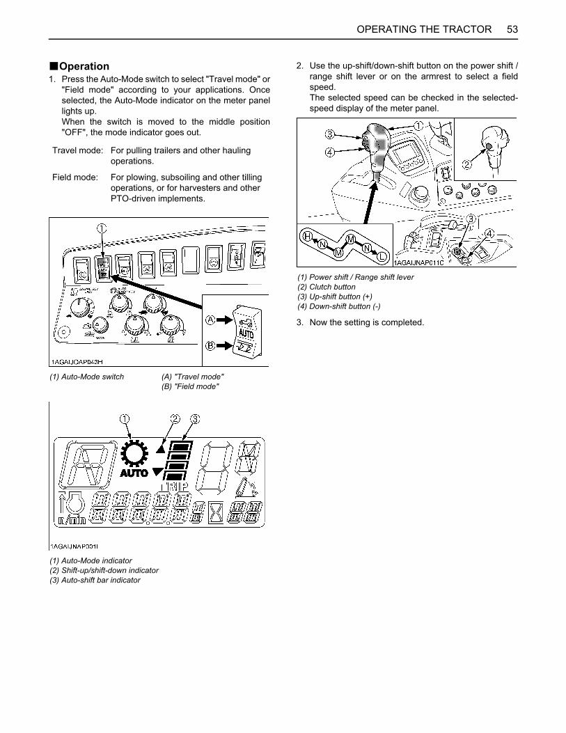
53OPERATING THE TRACTOR
BOperation1. Press the Auto-Mode switch to select "Travel mode" or
"Field mode" according to your applications. Onceselected, the Auto-Mode indicator on the meter panellights up.When the switch is moved to the middle position"OFF", the mode indicator goes out.
2. Use the up-shift/down-shift button on the power shift /range shift lever or on the armrest to select a fieldspeed. The selected speed can be checked in the selected-speed display of the meter panel.
3. Now the setting is completed.
Travel mode: For pulling trailers and other hauling operations.
Field mode: For plowing, subsoiling and other tilling operations, or for harvesters and other PTO-driven implements.
(1) Auto-Mode switch (A) "Travel mode"(B) "Field mode"
(1) Auto-Mode indicator(2) Shift-up/shift-down indicator(3) Auto-shift bar indicator
(1) Power shift / Range shift lever(2) Clutch button(3) Up-shift button (+)(4) Down-shift button (-)
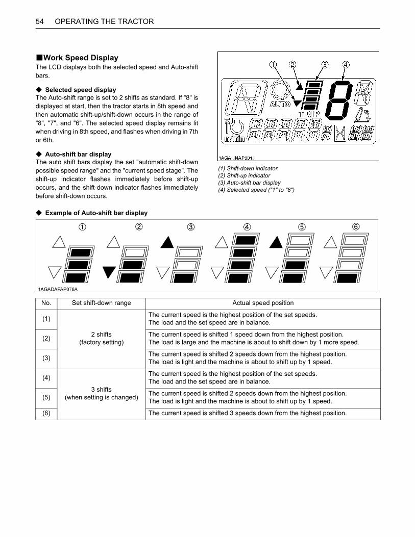
OPERATING THE TRACTOR54
BWork Speed DisplayThe LCD displays both the selected speed and Auto-shiftbars.
C Selected speed displayThe Auto-shift range is set to 2 shifts as standard. If "8" isdisplayed at start, then the tractor starts in 8th speed andthen automatic shift-up/shift-down occurs in the range of"8", "7", and "6". The selected speed display remains litwhen driving in 8th speed, and flashes when driving in 7thor 6th.
C Auto-shift bar displayThe auto shift bars display the set "automatic shift-downpossible speed range" and the "current speed stage". Theshift-up indicator flashes immediately before shift-upoccurs, and the shift-down indicator flashes immediatelybefore shift-down occurs.
C Example of Auto-shift bar display
(1) Shift-down indicator(2) Shift-up indicator(3) Auto-shift bar display(4) Selected speed ("1" to "8")
No. Set shift-down range Actual speed position
(1)
2 shifts(factory setting)
The current speed is the highest position of the set speeds. The load and the set speed are in balance.
(2) The current speed is shifted 1 speed down from the highest position.The load is large and the machine is about to shift down by 1 more speed.
(3) The current speed is shifted 2 speeds down from the highest position.The load is light and the machine is about to shift up by 1 speed.
(4)
3 shifts(when setting is changed)
The current speed is the highest position of the set speeds. The load and the set speed are in balance.
(5) The current speed is shifted 2 speeds down from the highest position.The load is light and the machine is about to shift up by 1 speed.
(6) The current speed is shifted 3 speeds down from the highest position.
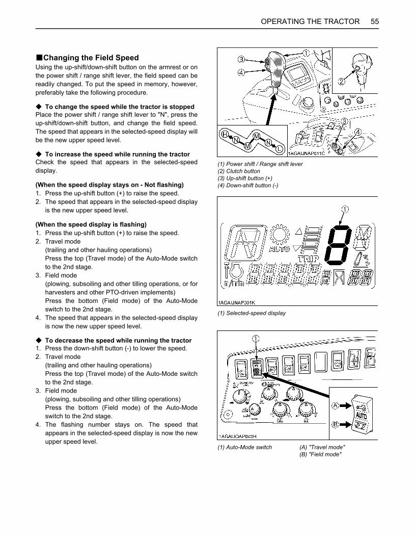
55OPERATING THE TRACTOR
BChanging the Field SpeedUsing the up-shift/down-shift button on the armrest or onthe power shift / range shift lever, the field speed can bereadily changed. To put the speed in memory, however,preferably take the following procedure.
C To change the speed while the tractor is stoppedPlace the power shift / range shift lever to "N", press theup-shift/down-shift button, and change the field speed.The speed that appears in the selected-speed display willbe the new upper speed level.
C To increase the speed while running the tractorCheck the speed that appears in the selected-speeddisplay.
(When the speed display stays on - Not flashing)1. Press the up-shift button (+) to raise the speed.2. The speed that appears in the selected-speed display
is the new upper speed level.
(When the speed display is flashing)1. Press the up-shift button (+) to raise the speed.2. Travel mode
(trailing and other hauling operations)Press the top (Travel mode) of the Auto-Mode switchto the 2nd stage.
3. Field mode(plowing, subsoiling and other tilling operations, or forharvesters and other PTO-driven implements)Press the bottom (Field mode) of the Auto-Modeswitch to the 2nd stage.
4. The speed that appears in the selected-speed displayis now the new upper speed level.
C To decrease the speed while running the tractor1. Press the down-shift button (-) to lower the speed.2. Travel mode
(trailing and other hauling operations)Press the top (Travel mode) of the Auto-Mode switchto the 2nd stage.
3. Field mode(plowing, subsoiling and other tilling operations)Press the bottom (Field mode) of the Auto-Modeswitch to the 2nd stage.
4. The flashing number stays on. The speed thatappears in the selected-speed display is now the newupper speed level.
(1) Power shift / Range shift lever(2) Clutch button(3) Up-shift button (+)(4) Down-shift button (-)
(1) Selected-speed display
(1) Auto-Mode switch (A) "Travel mode"(B) "Field mode"
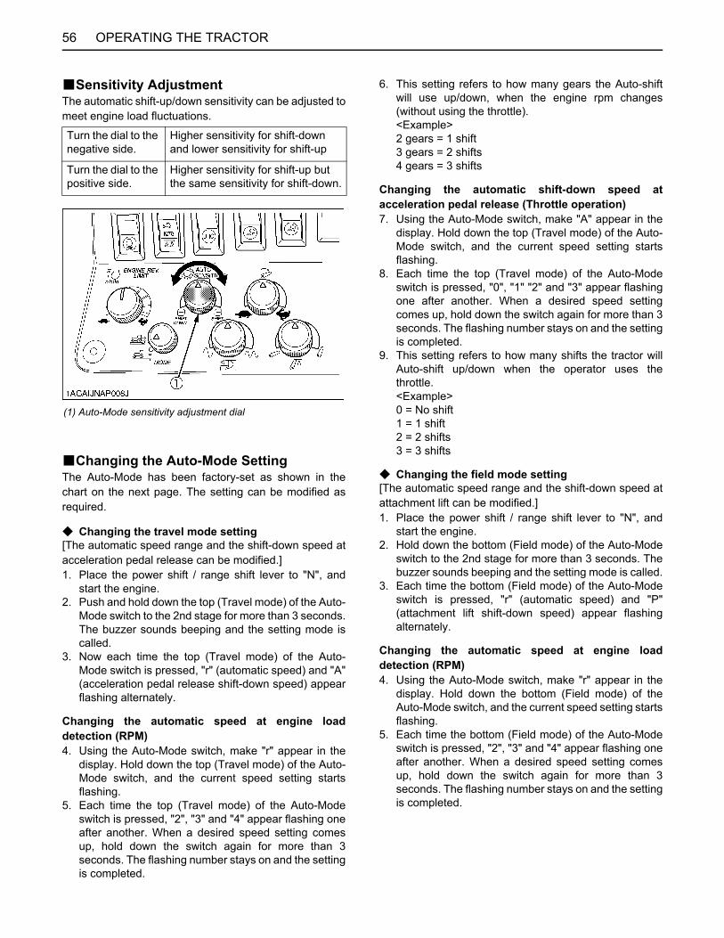
OPERATING THE TRACTOR56
BSensitivity AdjustmentThe automatic shift-up/down sensitivity can be adjusted tomeet engine load fluctuations.
BChanging the Auto-Mode SettingThe Auto-Mode has been factory-set as shown in thechart on the next page. The setting can be modified asrequired.
C Changing the travel mode setting[The automatic speed range and the shift-down speed atacceleration pedal release can be modified.]1. Place the power shift / range shift lever to "N", and
start the engine.2. Push and hold down the top (Travel mode) of the Auto-
Mode switch to the 2nd stage for more than 3 seconds.The buzzer sounds beeping and the setting mode iscalled.
3. Now each time the top (Travel mode) of the Auto-Mode switch is pressed, "r" (automatic speed) and "A"(acceleration pedal release shift-down speed) appearflashing alternately.
Changing the automatic speed at engine loaddetection (RPM)4. Using the Auto-Mode switch, make "r" appear in the
display. Hold down the top (Travel mode) of the Auto-Mode switch, and the current speed setting startsflashing.
5. Each time the top (Travel mode) of the Auto-Modeswitch is pressed, "2", "3" and "4" appear flashing oneafter another. When a desired speed setting comesup, hold down the switch again for more than 3seconds. The flashing number stays on and the settingis completed.
6. This setting refers to how many gears the Auto-shiftwill use up/down, when the engine rpm changes(without using the throttle).<Example>2 gears = 1 shift3 gears = 2 shifts4 gears = 3 shifts
Changing the automatic shift-down speed atacceleration pedal release (Throttle operation)7. Using the Auto-Mode switch, make "A" appear in the
display. Hold down the top (Travel mode) of the Auto-Mode switch, and the current speed setting startsflashing.
8. Each time the top (Travel mode) of the Auto-Modeswitch is pressed, "0", "1" "2" and "3" appear flashingone after another. When a desired speed settingcomes up, hold down the switch again for more than 3seconds. The flashing number stays on and the settingis completed.
9. This setting refers to how many shifts the tractor willAuto-shift up/down when the operator uses thethrottle.<Example>0 = No shift1 = 1 shift2 = 2 shifts3 = 3 shifts
C Changing the field mode setting[The automatic speed range and the shift-down speed atattachment lift can be modified.]1. Place the power shift / range shift lever to "N", and
start the engine.2. Hold down the bottom (Field mode) of the Auto-Mode
switch to the 2nd stage for more than 3 seconds. Thebuzzer sounds beeping and the setting mode is called.
3. Each time the bottom (Field mode) of the Auto-Modeswitch is pressed, "r" (automatic speed) and "P"(attachment lift shift-down speed) appear flashingalternately.
Changing the automatic speed at engine loaddetection (RPM)4. Using the Auto-Mode switch, make "r" appear in the
display. Hold down the bottom (Field mode) of theAuto-Mode switch, and the current speed setting startsflashing.
5. Each time the bottom (Field mode) of the Auto-Modeswitch is pressed, "2", "3" and "4" appear flashing oneafter another. When a desired speed setting comesup, hold down the switch again for more than 3seconds. The flashing number stays on and the settingis completed.
Turn the dial to the negative side.
Higher sensitivity for shift-down and lower sensitivity for shift-up
Turn the dial to the positive side.
Higher sensitivity for shift-up but the same sensitivity for shift-down.
(1) Auto-Mode sensitivity adjustment dial
57OPERATING THE TRACTOR
6. This setting refers to how many gears the Auto-shiftwill use up/down, when the engine rpm changes(without using the throttle).<Example>2 gears = 1 shift3 gears = 2 shifts4 gears = 3 shifts
Changing the automatic shift-down speed at 3-pointhitch lift7. Using the Auto-Mode switch, make "P" appear in the
display. Hold down the bottom (plow marking) of theAuto-Mode switch, and the current speed setting startsflashing.
8. Each time the bottom (plow marking) of the Auto-Modeswitch is pressed, "0", "1" "2" and "3" appear flashingone after another. When a desired speed settingcomes up, hold down the switch again for more than 3seconds. The flashing number stays on and the settingis completed.
9. This setting refers to how many shifts the tractor willAuto-shift down when the operator raises the 3-pointhitch.<Example>0 = No shift down1 = 1 shift2 = 2 shifts3 = 3 shifts
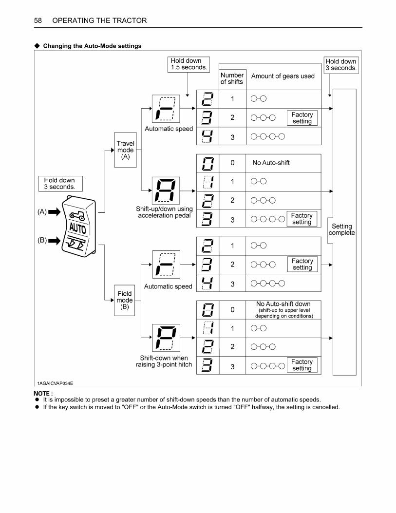
58 OPERATING THE TRACTOR
C Changing the Auto-Mode settings
A It is impossible to preset a greater number of shift-down speeds than the number of automatic speeds.A If the key switch is moved to "OFF" or the Auto-Mode switch is turned "OFF" halfway, the setting is cancelled.
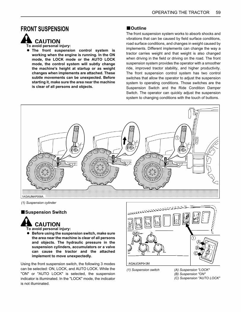
59OPERATING THE TRACTOR
FRONT SUSPENSION
To avoid personal injury:A The front suspension control system is
working when the engine is running. In the ONmode, the LOCK mode or the AUTO LOCKmode, the control system will subtly changethe machine's height at startup or as weightchanges when implements are attached. Thesesubtle movements can be unexpected. Beforestarting it, make sure the area near the machineis clear of all persons and objects.
BOutlineThe front suspension system works to absorb shocks andvibrations that can be caused by field surface conditions,road surface conditions, and changes in weight caused byimplements. Different implements can change the way atractor carries weight and that weight is also changedwhen driving in the field or driving on the road. The frontsuspension system provides the operator with a smootherride, improved tractor stability, and higher productivity.The front suspension control system has two controlswitches that allow the operator to adjust the suspensionsystem to operating conditions. Those switches are theSuspension Switch and the Ride Condition DamperSwitch. The operator can quickly adjust the suspensionsystem to changing conditions with the touch of buttons.
BSuspension Switch
To avoid personal injury:A Before using the suspension switch, make sure
the area near the machine is clear of all personsand objects. The hydraulic pressure in thesuspension cylinders, accumulators or a valvecan cause the tractor and the attachedimplement to move unexpectedly.
Using the front suspension switch, the following 3 modescan be selected: ON, LOCK, and AUTO LOCK. While the"ON" or "AUTO LOCK" is selected, the suspensionindicator is illuminated. In the "LOCK" mode, the indicatoris not illuminated.
(1) Suspension cylinder
(1) Suspension switch (A) Suspension "LOCK"(B) Suspension "ON"(C) Suspension "AUTO LOCK"

OPERATING THE TRACTOR60
C Suspension "ON" ModeWhether driving on roads or doing work, the ON modereacts to changing surface conditions and the changingweight of the tractor as implements are used. The ONmode is usually selected. When the ON mode is selected,the suspension indicator is illuminated.
C Suspension "LOCK (OFF)" ModeThe suspension system is locked out, and no suspensionaction takes place. The LOCK mode should be selectedwhen the operator needs to prevent the tractor and theattached implements from overcompensating the frontsuspension system. The suspension indicator does notilluminate when the LOCK mode is selected.
C Suspension "AUTO LOCK" ModeIn this mode, the suspension is automatically selectedLOCK or ON as listed in the table below. The suspension indicator is illuminated when the AUTOLOCK mode is selected.
Example: Front End Loader operation (positionmode)In order to efficiently perform Front End Loader work, thesuspension stays locked at lower speeds. This helps holdthe tractor in a stable condition. While traveling, thesuspension is turned on for comfortable ride.
Example: Plowing (draft mode)When a drafted load becomes heavy, the suspension getslocked. When the load becomes lighter, the suspension isturned on. In moving with the plow up, the suspension iskept on.
A In the AUTO LOCK mode, the hydraulic pressure inthe suspension cylinders, accumulators or a valvemay cause the machine height to change, when thesuspension system switches automatically from"LOCK" to "ON" status.
A The suspension cylinder adjustment control does notwork in the operating conditions below.(1) The front wheels are overloaded.(2) The engine runs at low speeds and the oil
temperature is high.(3) Both the brake pedals are stepped down.(4) The manual control mode is selected.
A The machine speed in the suspension auto lock modehas been factory-setting at below 3 km/h. To changethis setting, contact your local KUBOTA Dealer.
(1) Suspension indicator
3-PointHitchControlMode
Suspension
LOCK ON
Positionselected
A At low-speedtravel
A At lower 3-pointhitch
A While travellingA At higher 3-point
hitch
Draftselected
A With heavy draftload (at lower 3-point hitch)
A At lower travelspeed
A While the 3-P.Quick lowerswitch is pressed
A With light draftload (at lower 3-point hitch)
A At higher 3-pointhitch

61OPERATING THE TRACTOR
BRide Condition Damper SwitchThe suspension dampening can be adjusted by using theRide Condition Damper Switch. To adjust the suspensiondampening you must have the Suspension Switch set tothe ON mode or the AUTO LOCK mode. Set the RideCondition Damper Switch to match implement, groundconditions, and the type of work you are doing.
C Normal ModeIn Normal mode, the tractor will automatically select theoptimum dampening force between soft, medium, andfirm to insure the best ride. The suspension dampeningshould be selected based on the tractors gross weightwith implements. Of the three modes (Normal mode, Firmmode, Soft mode), Normal mode is generallyrecommended for most tractor work.
C Firm ModeIn Firm mode, the suspension damping is set one levelhigher than Normal mode. As an example, the operatorwould use Firm mode when working with heavyimplements to prevent "rocking" or excessive bouncing,for example a heavy round bale in the loader.
C Soft ModeIn Soft mode, the suspension system is set one levellower than Normal mode. As an example, the operatorwould use Soft mode when traveling on uneven or roughroad surfaces to obtain a more comfortable ride.
A Depending on the tractor gross weight, the "Firm" and"Soft" modes may work at nearly the same as the"Normal" mode.
BManual Control Mode
To avoid personal injury:A Before releasing the manual control mode,
make sure the area near the machine is clear ofall persons and objects.Because of the hydraulic pressure in thecylinder, the machine height may changeunexpectedly or the suspension cylinderadjustment control may get activated, whichaffects the height and/or posture of the tractoror the implement.
The tractor front end height can be raised or lowered bymoving the suspension cylinder in the manual control.This is useful in attaching and detaching a front implementor front weight.
C Height adjusting procedure1. Hold down the top (Firm mode) or the bottom (Soft
mode) of the ride condition damper switch to thesecond stage for more than 3 seconds, and the buzzerstarts beeping and the suspension indicator startsflashing (two or so flashes every second). Now themachine gets in the manual control mode.
2. Hold down the top (Firm mode) of the ride conditiondamper switch to the second stage, and the height israised.
3. Hold down the bottom (Soft mode) of the ride conditiondamper switch to the second stage, and the height islowered.
(1) Ride condition damper switch (A) "FIRM MODE"(B) "NORMAL MODE"(C) "SOFT MODE"
(1) Ride condition damperswitch
(A) "PRESS DOWN TO THESECOND STAGE"
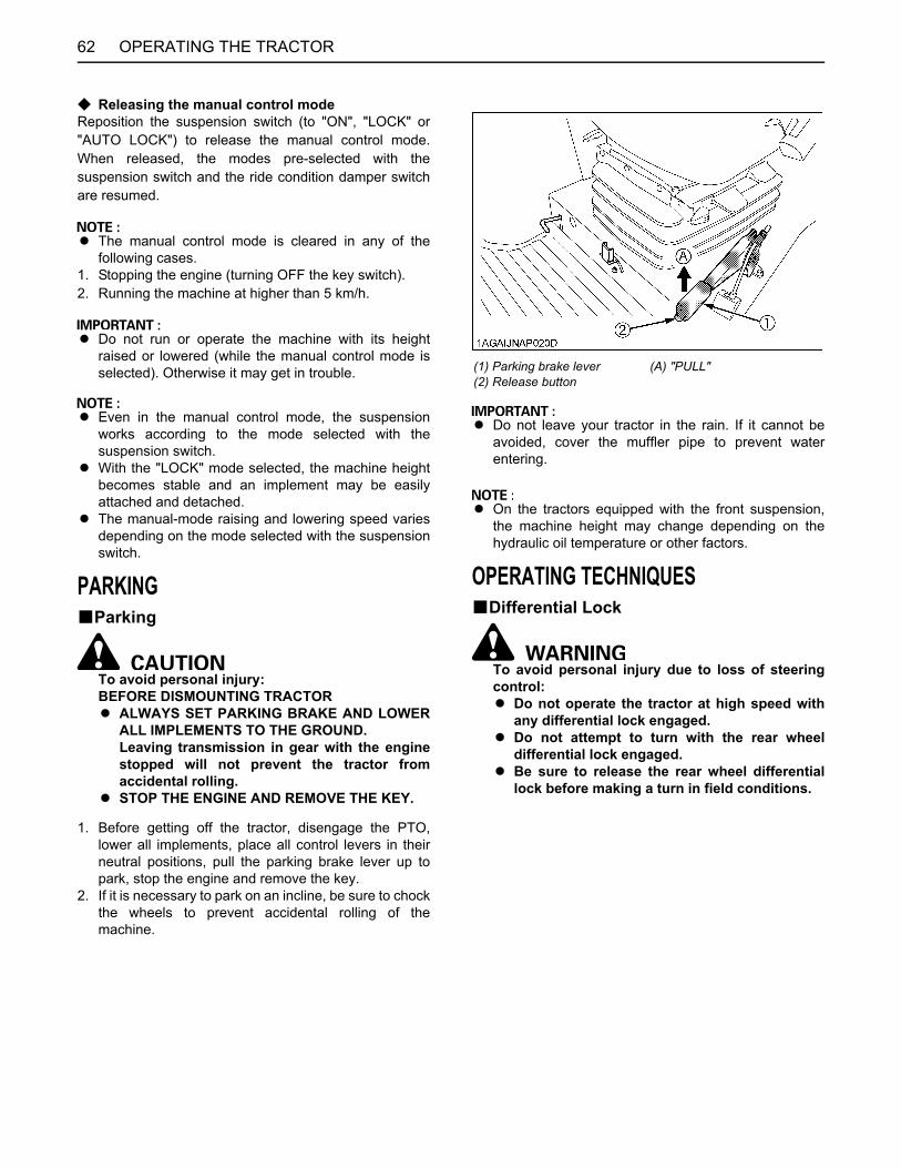
OPERATING THE TRACTOR62
C Releasing the manual control modeReposition the suspension switch (to "ON", "LOCK" or"AUTO LOCK") to release the manual control mode.When released, the modes pre-selected with thesuspension switch and the ride condition damper switchare resumed.
A The manual control mode is cleared in any of thefollowing cases.
1. Stopping the engine (turning OFF the key switch).2. Running the machine at higher than 5 km/h.
A Do not run or operate the machine with its heightraised or lowered (while the manual control mode isselected). Otherwise it may get in trouble.
A Even in the manual control mode, the suspensionworks according to the mode selected with thesuspension switch.
A With the "LOCK" mode selected, the machine heightbecomes stable and an implement may be easilyattached and detached.
A The manual-mode raising and lowering speed variesdepending on the mode selected with the suspensionswitch.
PARKINGBParking
To avoid personal injury:BEFORE DISMOUNTING TRACTORA ALWAYS SET PARKING BRAKE AND LOWER
ALL IMPLEMENTS TO THE GROUND.Leaving transmission in gear with the enginestopped will not prevent the tractor fromaccidental rolling.
A STOP THE ENGINE AND REMOVE THE KEY.
1. Before getting off the tractor, disengage the PTO,lower all implements, place all control levers in theirneutral positions, pull the parking brake lever up topark, stop the engine and remove the key.
2. If it is necessary to park on an incline, be sure to chockthe wheels to prevent accidental rolling of themachine.
A Do not leave your tractor in the rain. If it cannot beavoided, cover the muffler pipe to prevent waterentering.
A On the tractors equipped with the front suspension,the machine height may change depending on thehydraulic oil temperature or other factors.
OPERATING TECHNIQUESBDifferential Lock
To avoid personal injury due to loss of steeringcontrol:A Do not operate the tractor at high speed with
any differential lock engaged.A Do not attempt to turn with the rear wheel
differential lock engaged.A Be sure to release the rear wheel differential
lock before making a turn in field conditions.
(1) Parking brake lever(2) Release button
(A) "PULL"
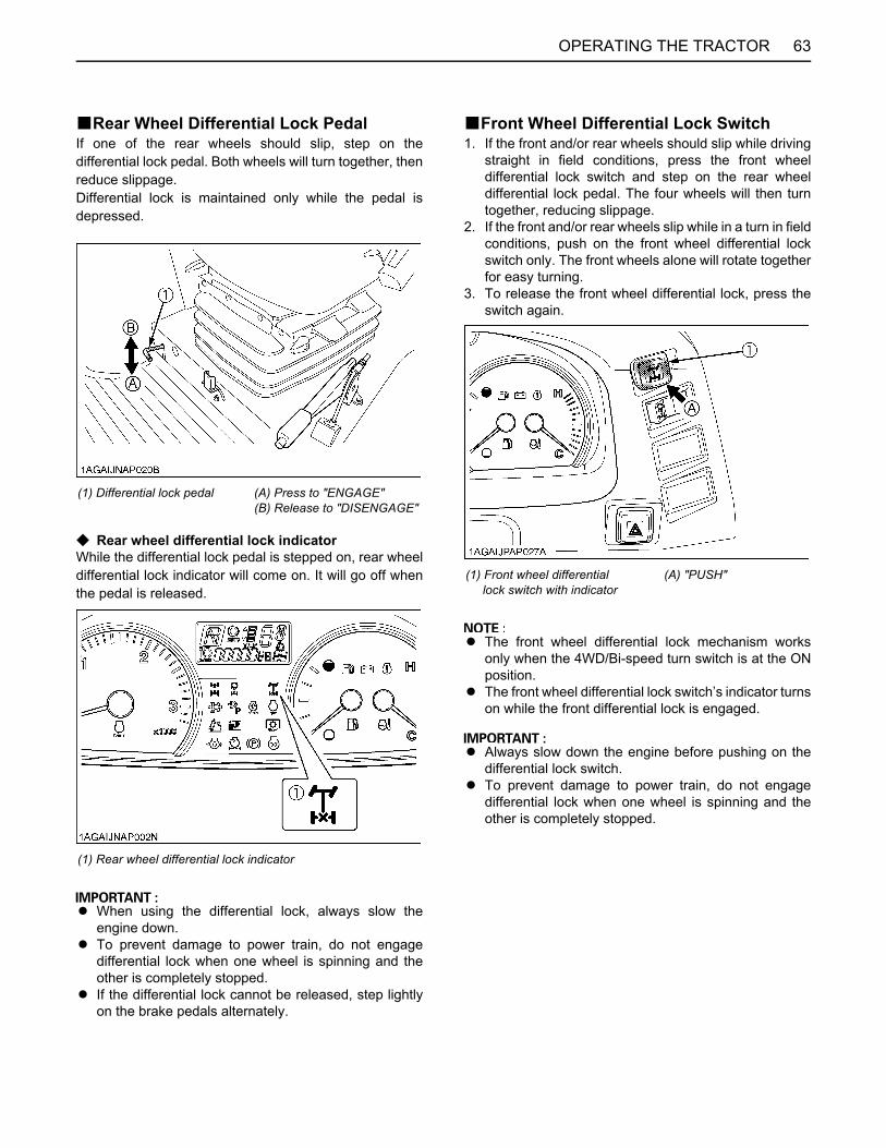
63OPERATING THE TRACTOR
BRear Wheel Differential Lock PedalIf one of the rear wheels should slip, step on thedifferential lock pedal. Both wheels will turn together, thenreduce slippage.Differential lock is maintained only while the pedal isdepressed.
C Rear wheel differential lock indicatorWhile the differential lock pedal is stepped on, rear wheeldifferential lock indicator will come on. It will go off whenthe pedal is released.
A When using the differential lock, always slow theengine down.
A To prevent damage to power train, do not engagedifferential lock when one wheel is spinning and theother is completely stopped.
A If the differential lock cannot be released, step lightlyon the brake pedals alternately.
BFront Wheel Differential Lock Switch1. If the front and/or rear wheels should slip while driving
straight in field conditions, press the front wheeldifferential lock switch and step on the rear wheeldifferential lock pedal. The four wheels will then turntogether, reducing slippage.
2. If the front and/or rear wheels slip while in a turn in fieldconditions, push on the front wheel differential lockswitch only. The front wheels alone will rotate togetherfor easy turning.
3. To release the front wheel differential lock, press theswitch again.
A The front wheel differential lock mechanism worksonly when the 4WD/Bi-speed turn switch is at the ONposition.
A The front wheel differential lock switch’s indicator turnson while the front differential lock is engaged.
A Always slow down the engine before pushing on thedifferential lock switch.
A To prevent damage to power train, do not engagedifferential lock when one wheel is spinning and theother is completely stopped.
(1) Differential lock pedal (A) Press to "ENGAGE"(B) Release to "DISENGAGE"
(1) Rear wheel differential lock indicator
(1) Front wheel differential lock switch with indicator
(A) "PUSH"
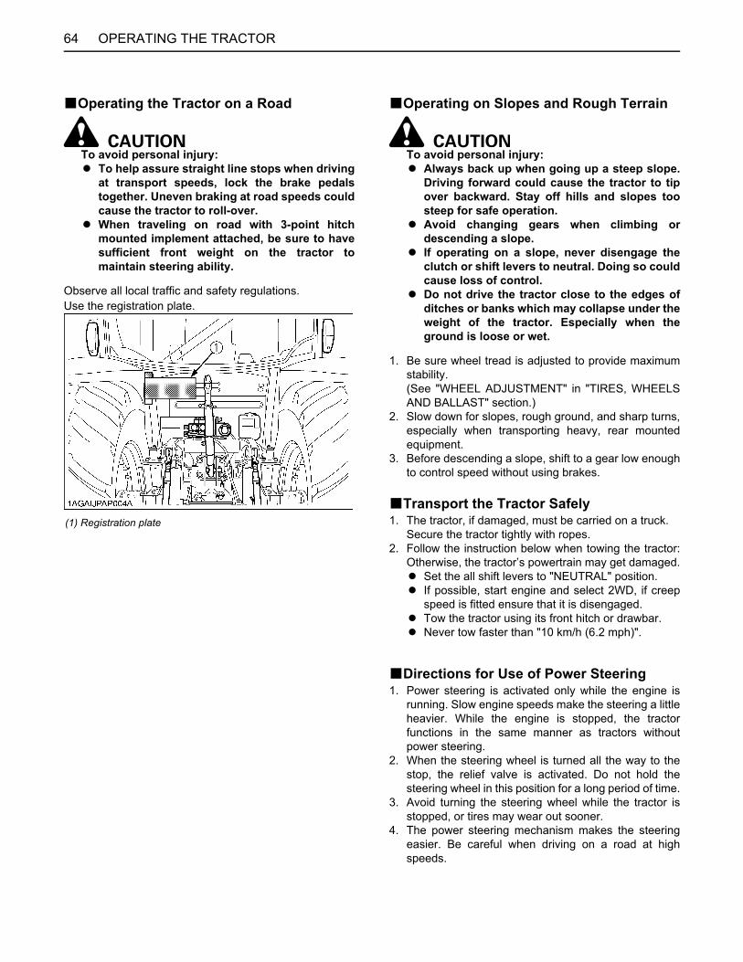
OPERATING THE TRACTOR64
BOperating the Tractor on a Road
To avoid personal injury:A To help assure straight line stops when driving
at transport speeds, lock the brake pedalstogether. Uneven braking at road speeds couldcause the tractor to roll-over.
A When traveling on road with 3-point hitchmounted implement attached, be sure to havesufficient front weight on the tractor tomaintain steering ability.
Observe all local traffic and safety regulations.Use the registration plate.
BOperating on Slopes and Rough Terrain
To avoid personal injury:A Always back up when going up a steep slope.
Driving forward could cause the tractor to tipover backward. Stay off hills and slopes toosteep for safe operation.
A Avoid changing gears when climbing ordescending a slope.
A If operating on a slope, never disengage theclutch or shift levers to neutral. Doing so couldcause loss of control.
A Do not drive the tractor close to the edges ofditches or banks which may collapse under theweight of the tractor. Especially when theground is loose or wet.
1. Be sure wheel tread is adjusted to provide maximumstability.(See "WHEEL ADJUSTMENT" in "TIRES, WHEELSAND BALLAST" section.)
2. Slow down for slopes, rough ground, and sharp turns,especially when transporting heavy, rear mountedequipment.
3. Before descending a slope, shift to a gear low enoughto control speed without using brakes.
BTransport the Tractor Safely1. The tractor, if damaged, must be carried on a truck.
Secure the tractor tightly with ropes.2. Follow the instruction below when towing the tractor:
Otherwise, the tractor’s powertrain may get damaged.A Set the all shift levers to "NEUTRAL" position.A If possible, start engine and select 2WD, if creep
speed is fitted ensure that it is disengaged.A Tow the tractor using its front hitch or drawbar.A Never tow faster than "10 km/h (6.2 mph)".
BDirections for Use of Power Steering1. Power steering is activated only while the engine is
running. Slow engine speeds make the steering a littleheavier. While the engine is stopped, the tractorfunctions in the same manner as tractors withoutpower steering.
2. When the steering wheel is turned all the way to thestop, the relief valve is activated. Do not hold thesteering wheel in this position for a long period of time.
3. Avoid turning the steering wheel while the tractor isstopped, or tires may wear out sooner.
4. The power steering mechanism makes the steeringeasier. Be careful when driving on a road at highspeeds.
(1) Registration plate

65OPERATING THE TRACTOR
BTrailer Electrical OutletA trailer electrical outlet is supplied for use with trailer orimplement.
C Function of each terminals in trailer electricaloutlet
(1) Trailer electrical outlet
Terminal Function
(1) Turn signal light (LH)
(2) ---
(3) Ground
(4) Turn signal light (RH)
(5)Tail lightSidemarker lightParking light
(6) Brake stop light
(7) Registration plate light

66 PTO
PTO
PTO OPERATIONTo avoid personal injury:A Disengage PTO, stop engine, and allow all
rotating components to come to a completestop before connecting, disconnecting,adjusting, or cleaning any PTO drivenequipment.
BPTO Clutch Control SwitchThe PTO clutch control switch engages or disengages thePTO clutch which gives the PTO independent control.Turn the switch to "ON" to engage the PTO clutch. Turnthe switch to "OFF" to disengage the PTO clutch.
C PTO Clutch Control Switch
To turn ONWhile pushing the switch, turn clockwise to the " "position and release your hand. (In the ON position,switch slightly rises itself.)
To Turn OFFTap on top of the switch, and the switch will return to theOFF position.
A To avoid shock loads to the PTO, reduce enginespeed when engaging the PTO, then open the throttleto the recommended speed.
A Tractor engine will not start if PTO clutch control switchis in the engaged "ON" position.
A If the PTO system is engaged and you stand up fromthe seat, the warning buzzer will whistle for about 10seconds after standing up.This is because the tractor is equipped with "OperatorPresence Control System".
(1) PTO clutch control switch "ON" "OFF"
(A) "PUSH"
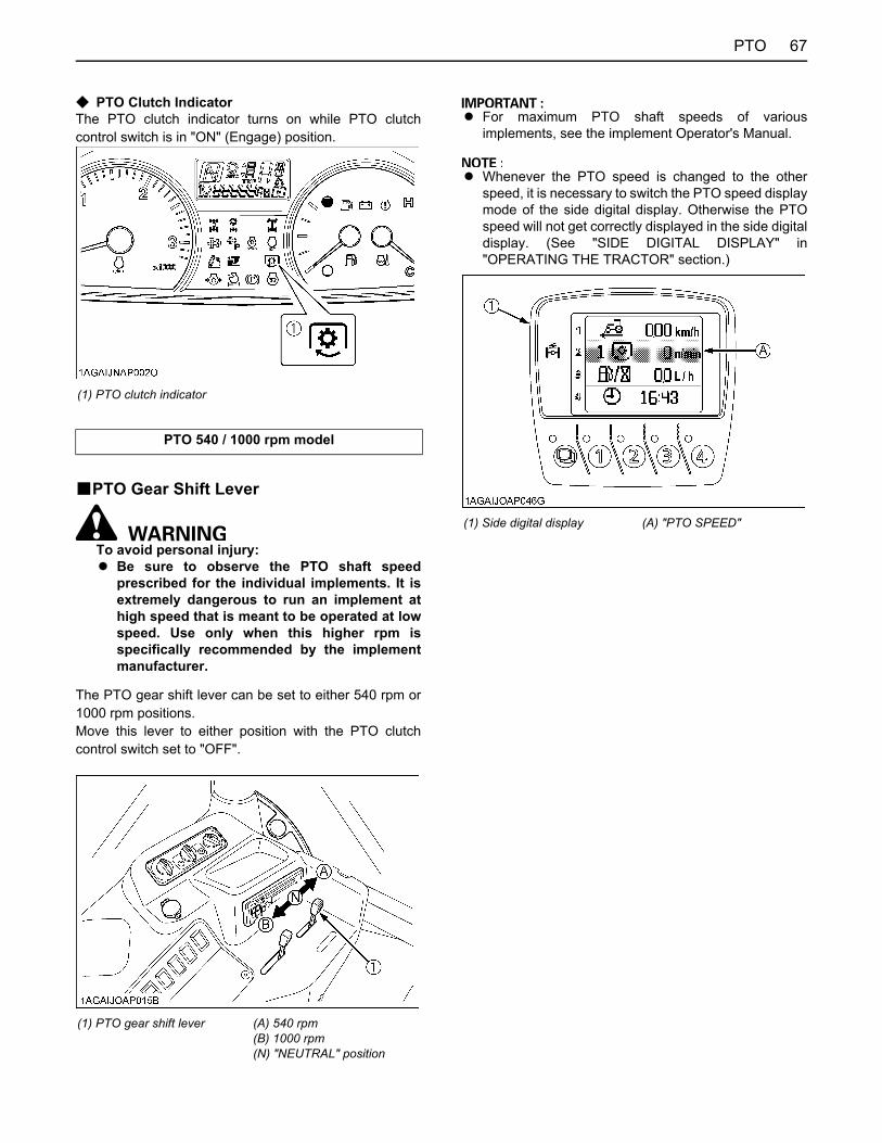
67PTO
C PTO Clutch IndicatorThe PTO clutch indicator turns on while PTO clutchcontrol switch is in "ON" (Engage) position.
BPTO Gear Shift Lever
To avoid personal injury:A Be sure to observe the PTO shaft speed
prescribed for the individual implements. It isextremely dangerous to run an implement athigh speed that is meant to be operated at lowspeed. Use only when this higher rpm isspecifically recommended by the implementmanufacturer.
The PTO gear shift lever can be set to either 540 rpm or1000 rpm positions.Move this lever to either position with the PTO clutchcontrol switch set to "OFF".
A For maximum PTO shaft speeds of variousimplements, see the implement Operator's Manual.
A Whenever the PTO speed is changed to the otherspeed, it is necessary to switch the PTO speed displaymode of the side digital display. Otherwise the PTOspeed will not get correctly displayed in the side digitaldisplay. (See "SIDE DIGITAL DISPLAY" in"OPERATING THE TRACTOR" section.)
(1) PTO clutch indicator
PTO 540 / 1000 rpm model
(1) PTO gear shift lever (A) 540 rpm(B) 1000 rpm(N) "NEUTRAL" position
(1) Side digital display (A) "PTO SPEED"
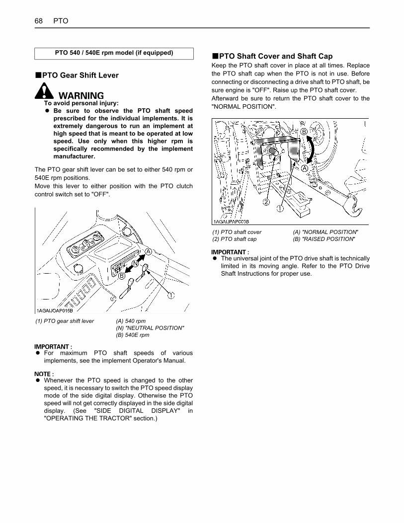
PTO68
BPTO Gear Shift Lever
To avoid personal injury:A Be sure to observe the PTO shaft speed
prescribed for the individual implements. It isextremely dangerous to run an implement athigh speed that is meant to be operated at lowspeed. Use only when this higher rpm isspecifically recommended by the implementmanufacturer.
The PTO gear shift lever can be set to either 540 rpm or540E rpm positions.Move this lever to either position with the PTO clutchcontrol switch set to "OFF".
A For maximum PTO shaft speeds of variousimplements, see the implement Operator's Manual.
A Whenever the PTO speed is changed to the otherspeed, it is necessary to switch the PTO speed displaymode of the side digital display. Otherwise the PTOspeed will not get correctly displayed in the side digitaldisplay. (See "SIDE DIGITAL DISPLAY" in"OPERATING THE TRACTOR" section.)
BPTO Shaft Cover and Shaft CapKeep the PTO shaft cover in place at all times. Replacethe PTO shaft cap when the PTO is not in use. Beforeconnecting or disconnecting a drive shaft to PTO shaft, besure engine is "OFF". Raise up the PTO shaft cover.Afterward be sure to return the PTO shaft cover to the"NORMAL POSITION".
A The universal joint of the PTO drive shaft is technicallylimited in its moving angle. Refer to the PTO DriveShaft Instructions for proper use.
PTO 540 / 540E rpm model (if equipped)
(1) PTO gear shift lever (A) 540 rpm(N) "NEUTRAL POSITION"(B) 540E rpm
(1) PTO shaft cover(2) PTO shaft cap
(A) "NORMAL POSITION"(B) "RAISED POSITION"
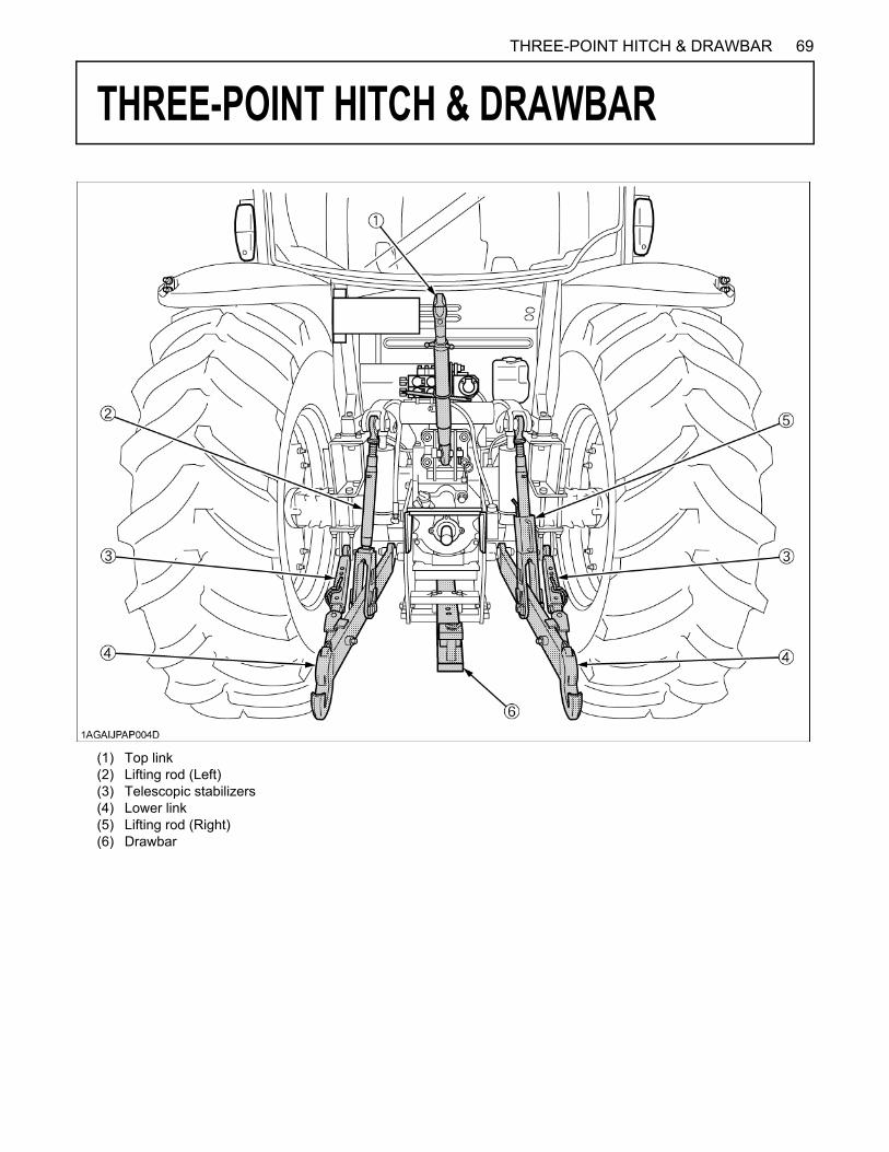
69THREE-POINT HITCH & DRAWBAR
THREE-POINT HITCH & DRAWBAR
(1) Top link(2) Lifting rod (Left)(3) Telescopic stabilizers(4) Lower link(5) Lifting rod (Right)(6) Drawbar
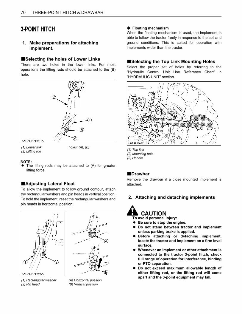
THREE-POINT HITCH & DRAWBAR70
3-POINT HITCH
BSelecting the holes of Lower LinksThere are two holes in the lower links. For mostoperations the lifting rods should be attached to the (B)hole.
A The lifting rods may be attached to (A) for greaterlifting force.
BAdjusting Lateral FloatTo allow the implement to follow ground contour, attachthe rectangular washers and pin heads in vertical position.To hold the implement, reset the rectangular washers andpin heads in horizontal position.
C Floating mechanismWhen the floating mechanism is used, the implement isable to follow the tractor freely in response to the soil andground conditions. This is suited for operation withimplements wider than the tractor.
BSelecting the Top Link Mounting HolesSelect the proper set of holes by referring to the"Hydraulic Control Unit Use Reference Chart" in"HYDRAULIC UNIT" section.
BDrawbarRemove the drawbar if a close mounted implement isattached.
To avoid personal injury:A Be sure to stop the engine.A Do not stand between tractor and implement
unless parking brake is applied.A Before attaching or detaching implement,
locate the tractor and implement on a firm levelsurface.
A Whenever an implement or other attachment isconnected to the tractor 3-point hitch, checkfull range of operation for interference, bindingor PTO separation.
A Do not exceed maximum allowable length ofeither lifting rod, or the lifting rod will comeapart and the 3-point equipment may fall.
1. Make preparations for attaching implement.
(1) Lower link(2) Lifting rod
holes: (A), (B)
(1) Rectangular washer(2) Pin head
(A) Horizontal position(B) Vertical position
(1) Top link(2) Mounting hole(3) Handle
2. Attaching and detaching implements
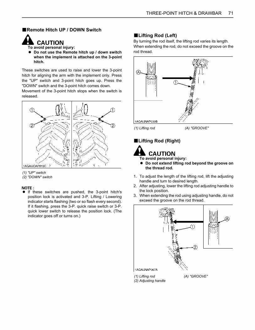
71THREE-POINT HITCH & DRAWBAR
BRemote Hitch UP / DOWN Switch
To avoid personal injury:A Do not use the Remote hitch up / down switch
when the implement is attached on the 3-pointhitch.
These switches are used to raise and lower the 3-pointhitch for aligning the arm with the implement only. Pressthe "UP" switch and 3-point hitch goes up. Press the"DOWN" switch and the 3-point hitch comes down.Movement of the 3-point hitch stops when the switch isreleased.
A If these switches are pushed, the 3-point hitch'sposition lock is activated and 3-P. Lifting / Loweringindicator starts flashing (two or so flash every second).If it flashing, press the 3-P. quick raise switch or 3-P.quick lower switch to release the position lock. (Theindicator goes off or turns on.)
BLifting Rod (Left)By turning the rod itself, the lifting rod varies its length.When extending the rod, do not exceed the groove on therod thread.
BLifting Rod (Right)
To avoid personal injury:A Do not extend lifting rod beyond the groove on
the thread rod.
1. To adjust the length of the lifting rod, lift the adjustinghandle and turn to desired length.
2. After adjusting, lower the lifting rod adjusting handle tothe lock position.
3. When extending the rod using adjusting handle, do notexceed the groove on the rod thread.
(1) "UP" switch(2) "DOWN" switch
(1) Lifting rod (A) "GROOVE"
(1) Lifting rod(2) Adjusting handle
(A) "GROOVE"
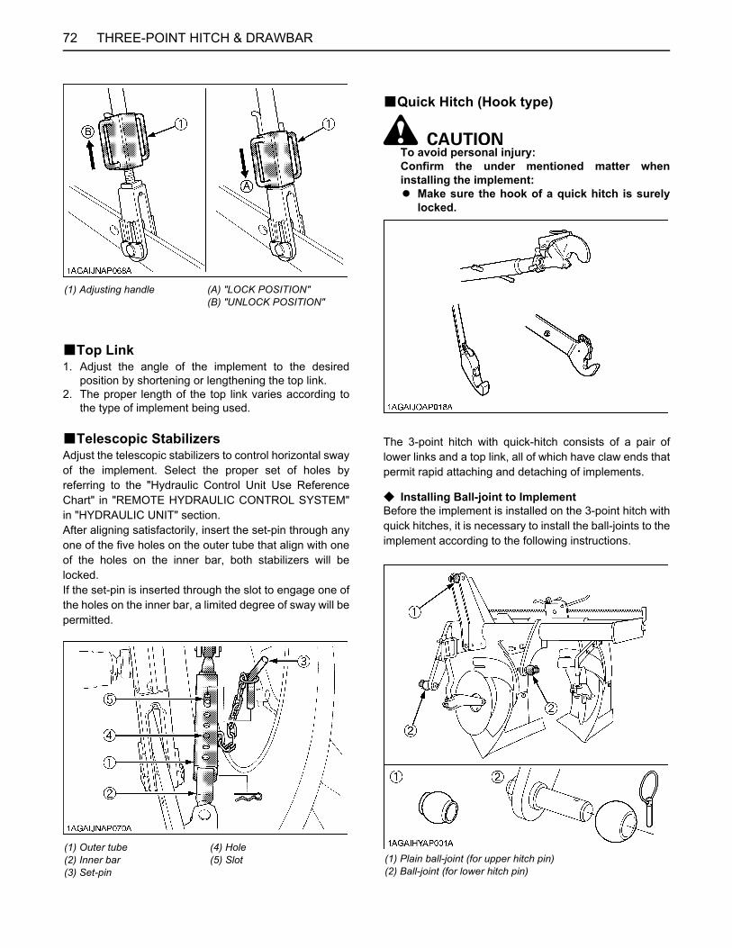
THREE-POINT HITCH & DRAWBAR72
BTop Link1. Adjust the angle of the implement to the desired
position by shortening or lengthening the top link.2. The proper length of the top link varies according to
the type of implement being used.
BTelescopic StabilizersAdjust the telescopic stabilizers to control horizontal swayof the implement. Select the proper set of holes byreferring to the "Hydraulic Control Unit Use ReferenceChart" in "REMOTE HYDRAULIC CONTROL SYSTEM"in "HYDRAULIC UNIT" section.After aligning satisfactorily, insert the set-pin through anyone of the five holes on the outer tube that align with oneof the holes on the inner bar, both stabilizers will belocked.If the set-pin is inserted through the slot to engage one ofthe holes on the inner bar, a limited degree of sway will bepermitted.
BQuick Hitch (Hook type)
To avoid personal injury:Confirm the under mentioned matter wheninstalling the implement:A Make sure the hook of a quick hitch is surely
locked.
The 3-point hitch with quick-hitch consists of a pair oflower links and a top link, all of which have claw ends thatpermit rapid attaching and detaching of implements.
C Installing Ball-joint to ImplementBefore the implement is installed on the 3-point hitch withquick hitches, it is necessary to install the ball-joints to theimplement according to the following instructions.
(1) Adjusting handle (A) "LOCK POSITION"(B) "UNLOCK POSITION"
(1) Outer tube(2) Inner bar(3) Set-pin
(4) Hole(5) Slot (1) Plain ball-joint (for upper hitch pin)
(2) Ball-joint (for lower hitch pin)
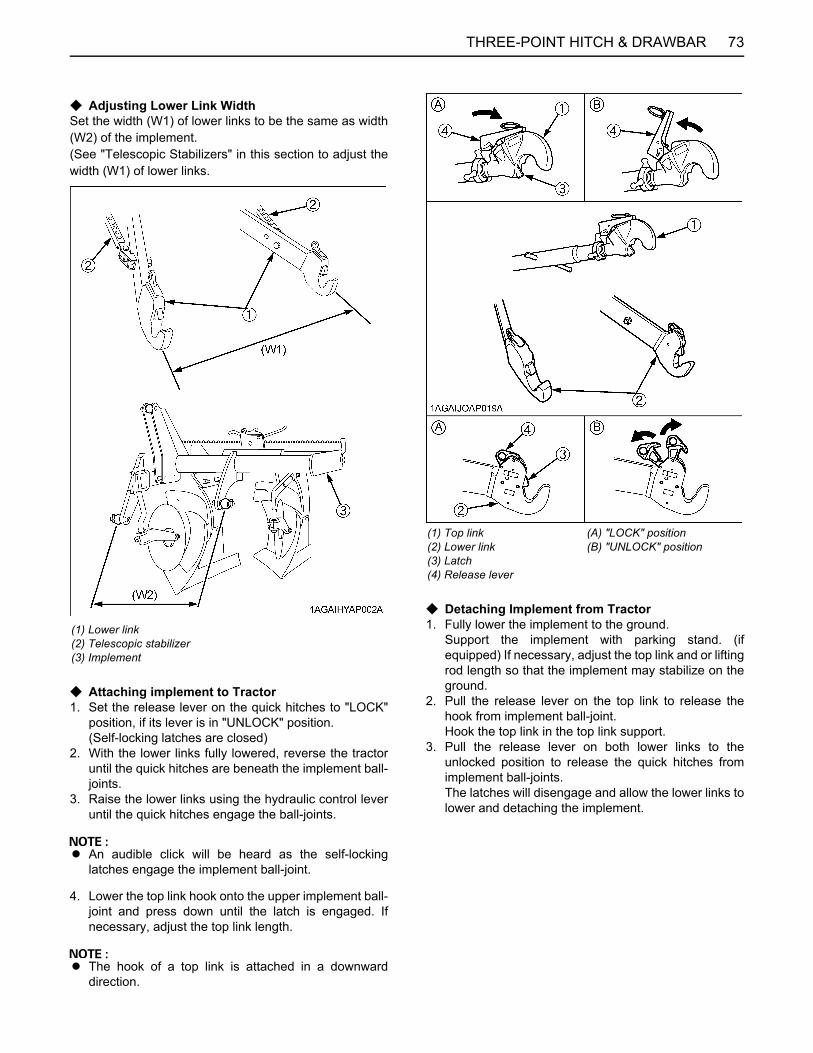
73THREE-POINT HITCH & DRAWBAR
C Adjusting Lower Link WidthSet the width (W1) of lower links to be the same as width(W2) of the implement.(See "Telescopic Stabilizers" in this section to adjust thewidth (W1) of lower links.
C Attaching implement to Tractor1. Set the release lever on the quick hitches to "LOCK"
position, if its lever is in "UNLOCK" position.(Self-locking latches are closed)
2. With the lower links fully lowered, reverse the tractoruntil the quick hitches are beneath the implement ball-joints.
3. Raise the lower links using the hydraulic control leveruntil the quick hitches engage the ball-joints.
A An audible click will be heard as the self-lockinglatches engage the implement ball-joint.
4. Lower the top link hook onto the upper implement ball-joint and press down until the latch is engaged. Ifnecessary, adjust the top link length.
A The hook of a top link is attached in a downwarddirection.
C Detaching Implement from Tractor1. Fully lower the implement to the ground.
Support the implement with parking stand. (ifequipped) If necessary, adjust the top link and or liftingrod length so that the implement may stabilize on theground.
2. Pull the release lever on the top link to release thehook from implement ball-joint.Hook the top link in the top link support.
3. Pull the release lever on both lower links to theunlocked position to release the quick hitches fromimplement ball-joints.The latches will disengage and allow the lower links tolower and detaching the implement.
(1) Lower link(2) Telescopic stabilizer(3) Implement
(1) Top link(2) Lower link(3) Latch(4) Release lever
(A) "LOCK" position(B) "UNLOCK" position

THREE-POINT HITCH & DRAWBAR74
DRAWBAR
To avoid personal injury:A Never pull from the top link, the rear axle or any
point above the drawbar. Doing so could causethe tractor to tip over rearward causingpersonal injury or death.
BAdjusting Drawbar LengthWhen towing an implement, it is recommended that the(A) hole in drawbar be utilized.The drawbar load is specified in the "IMPLEMENTLIMITATIONS" section.
BSwing DrawbarThe drawbar can be used in three different ways asillustrated below. Assemble it correctly with drawbar pins.
(1) Drawbar(2) Pivot pin
Holes: (A), (B)
(1) Drawbar(2) Locating pin(3) Looseness preventing bolt

75HYDRAULIC UNIT
HYDRAULIC UNIT
The standard tractor has following hydraulic controlsystems as shown below. Therefore, use the mostappropriate system for the implement you are using.C 3-Point Hitch Control System1. Position Control2. Mixed Draft Control
C Remote Hydraulic Control System
A Do not operate until the engine is warmed up. Ifoperation is attempted when the engine is still cold, thehydraulic system may be damaged.
A If noises are heard when implement is lifting after thehydraulic control lever has been activated, thehydraulic mechanism is not adjusted properly. Unlesscorrected, the unit will be damaged. Contact yourKUBOTA Dealer for adjustment.
3-POINT HITCH CONTROL SYSTEM
To avoid personal injury:A Before using the 3-point hitch controls, ensure
that no person or object is in the area of theimplement or 3-point hitch. Do not stand on ornear the implement or between the implementand tractor when operating the 3-point hitchcontrols.
BTerminology
(1) Bottom limit control dial
(2) Hydraulic control lever
(3) Mode selector switch
(4) 3-P. Quick lower switch
(5) 3-P. Quick raise switch
(6) Draft ratio adjustment dial
(7) Lift arm top limit adjustment dial
(8) 3-point hitch lowering speed adjustment dial
(9) 3-point hitch lowering lock lever
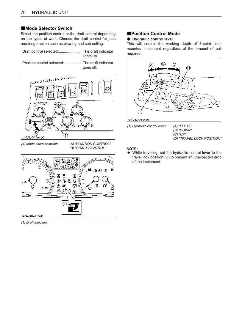
HYDRAULIC UNIT76
BMode Selector SwitchSelect the position control or the draft control dependingon the types of work. Choose the draft control for jobsrequiring traction such as plowing and sub-soiling.
BPosition Control ModeC Hydraulic control leverThis will control the working depth of 3-point hitchmounted implement regardless of the amount of pullrequired.
A While traveling, set the hydraulic control lever to thetravel lock position (D) to prevent an unexpected dropof the implement.
Draft control selected:.................... The draft indicator lights up.
Position control selected:............... The draft indicator goes off.
(1) Mode selector switch (A) "POSITION CONTROL"(B) "DRAFT CONTROL"
(1) Draft indicator
(1) Hydraulic control lever (A) "FLOAT"(B) "DOWN"(C) "UP"(D) "TRAVEL LOCK POSITION"
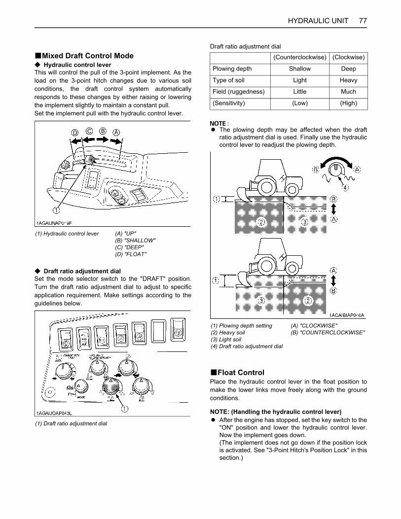
77HYDRAULIC UNIT
BMixed Draft Control ModeC Hydraulic control leverThis will control the pull of the 3-point implement. As theload on the 3-point hitch changes due to various soilconditions, the draft control system automaticallyresponds to these changes by either raising or loweringthe implement slightly to maintain a constant pull.Set the implement pull with the hydraulic control lever.
C Draft ratio adjustment dialSet the mode selector switch to the "DRAFT" position.Turn the draft ratio adjustment dial to adjust to specificapplication requirement. Make settings according to theguidelines below.
Draft ratio adjustment dial
A The plowing depth may be affected when the draftratio adjustment dial is used. Finally use the hydrauliccontrol lever to readjust the plowing depth.
BFloat ControlPlace the hydraulic control lever in the float position tomake the lower links move freely along with the groundconditions.
NOTE: (Handling the hydraulic control lever)A After the engine has stopped, set the key switch to the
"ON" position and lower the hydraulic control lever.Now the implement goes down.(The implement does not go down if the position lockis activated. See "3-Point Hitch's Position Lock" in thissection.)
(1) Hydraulic control lever (A) "UP"(B) "SHALLOW"(C) "DEEP"(D) "FLOAT"
(1) Draft ratio adjustment dial
(Counterclockwise) (Clockwise)
Plowing depth Shallow Deep
Type of soil Light Heavy
Field (ruggedness) Little Much
(Sensitivity) (Low) (High)
(1) Plowing depth setting(2) Heavy soil(3) Light soil(4) Draft ratio adjustment dial
(A) "CLOCKWISE"(B) "COUNTERCLOCKWISE"
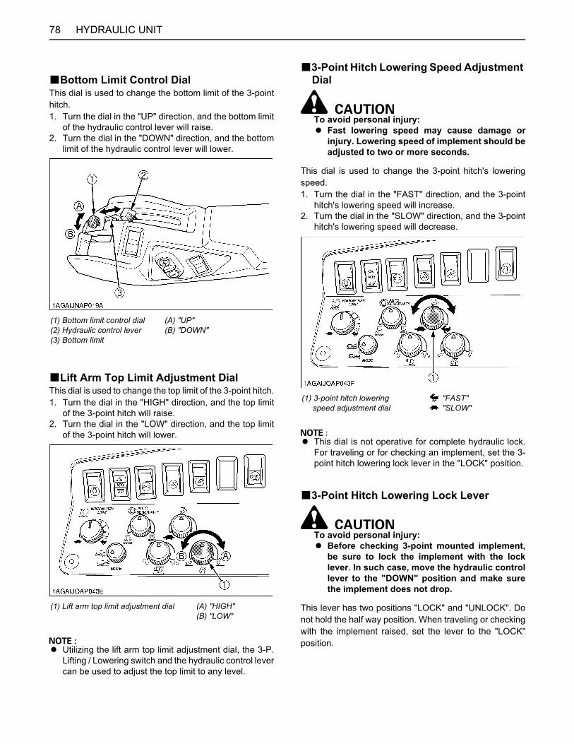
HYDRAULIC UNIT78
BBottom Limit Control DialThis dial is used to change the bottom limit of the 3-pointhitch.1. Turn the dial in the "UP" direction, and the bottom limit
of the hydraulic control lever will raise.2. Turn the dial in the "DOWN" direction, and the bottom
limit of the hydraulic control lever will lower.
BLift Arm Top Limit Adjustment DialThis dial is used to change the top limit of the 3-point hitch.1. Turn the dial in the "HIGH" direction, and the top limit
of the 3-point hitch will raise.2. Turn the dial in the "LOW" direction, and the top limit
of the 3-point hitch will lower.
A Utilizing the lift arm top limit adjustment dial, the 3-P.Lifting / Lowering switch and the hydraulic control levercan be used to adjust the top limit to any level.
B3-Point Hitch Lowering Speed Adjustment Dial
To avoid personal injury:A Fast lowering speed may cause damage or
injury. Lowering speed of implement should beadjusted to two or more seconds.
This dial is used to change the 3-point hitch's loweringspeed.1. Turn the dial in the "FAST" direction, and the 3-point
hitch's lowering speed will increase.2. Turn the dial in the "SLOW" direction, and the 3-point
hitch's lowering speed will decrease.
A This dial is not operative for complete hydraulic lock.For traveling or for checking an implement, set the 3-point hitch lowering lock lever in the "LOCK" position.
B3-Point Hitch Lowering Lock Lever
To avoid personal injury:A Before checking 3-point mounted implement,
be sure to lock the implement with the locklever. In such case, move the hydraulic controllever to the "DOWN" position and make surethe implement does not drop.
This lever has two positions "LOCK" and "UNLOCK". Donot hold the half way position. When traveling or checkingwith the implement raised, set the lever to the "LOCK"position.
(1) Bottom limit control dial(2) Hydraulic control lever(3) Bottom limit
(A) "UP"(B) "DOWN"
(1) Lift arm top limit adjustment dial (A) "HIGH"(B) "LOW"
(1) 3-point hitch lowering speed adjustment dial
"FAST" "SLOW"
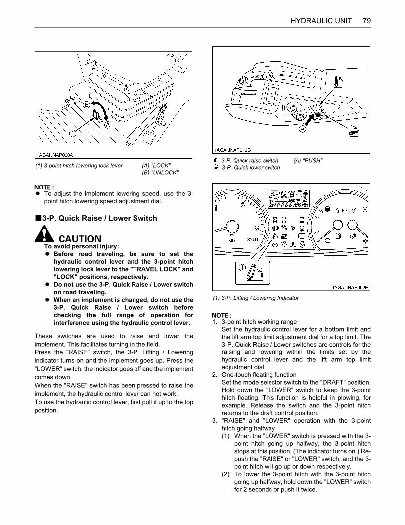
79HYDRAULIC UNIT
A To adjust the implement lowering speed, use the 3-point hitch lowering speed adjustment dial.
B3-P. Quick Raise / Lower Switch
To avoid personal injury:A Before road traveling, be sure to set the
hydraulic control lever and the 3-point hitchlowering lock lever to the "TRAVEL LOCK" and"LOCK" positions, respectively.
A Do not use the 3-P. Quick Raise / Lower switchon road traveling.
A When an implement is changed, do not use the3-P. Quick Raise / Lower switch beforechecking the full range of operation forinterference using the hydraulic control lever.
These switches are used to raise and lower theimplement. This facilitates turning in the field.Press the "RAISE" switch, the 3-P. Lifting / Loweringindicator turns on and the implement goes up. Press the"LOWER" switch, the indicator goes off and the implementcomes down.When the "RAISE" switch has been pressed to raise theimplement, the hydraulic control lever can not work.To use the hydraulic control lever, first pull it up to the topposition.
1. 3-point hitch working rangeSet the hydraulic control lever for a bottom limit andthe lift arm top limit adjustment dial for a top limit. The3-P. Quick Raise / Lower switches are controls for theraising and lowering within the limits set by thehydraulic control lever and the lift arm top limitadjustment dial.
2. One-touch floating functionSet the mode selector switch to the "DRAFT" position.Hold down the "LOWER" switch to keep the 3-pointhitch floating. This function is helpful in plowing, forexample. Release the switch and the 3-point hitchreturns to the draft control position.
3. "RAISE" and "LOWER" operation with the 3-pointhitch going halfway(1) When the "LOWER" switch is pressed with the 3-
point hitch going up halfway, the 3-point hitchstops at this position. (The indicator turns on.) Re-push the "RAISE" or "LOWER" switch, and the 3-point hitch will go up or down respectively.
(2) To lower the 3-point hitch with the 3-point hitchgoing up halfway, hold down the "LOWER" switchfor 2 seconds or push it twice.
(1) 3-point hitch lowering lock lever (A) "LOCK"(B) "UNLOCK"
3-P. Quick raise switch 3-P. Quick lower switch
(A) "PUSH"
(1) 3-P. Lifting / Lowering Indicator

HYDRAULIC UNIT80
(3) When the "RAISE" switch is pressed with the 3-point hitch going down halfway, the 3-point hitchgoes up.
B3-Point Hitch's Position LockC Position LockIf any of the following actions are made with the hydrauliccontrol lever and the lower links at different heights, theposition lock is activated. The 3-point hitch control isinterrupted and the 3-P. Lifting / Lowering indicator startsflashing (two or so flashes every second).1. Starting the engine.2. Activating the 3-P. Remote hitch Up / Down switch.3. Changing the mode selector switch.
C Releasing the position lockIf applied, press the 3-P. Quick Raise switch or 3-P. QuickLower switch.
A When the position lock is released with the 3-P. QuickRaise / Lower switches, the 3-point hitch goes up ordown.
REMOTE HYDRAULIC CONTROL SYSTEMThe hydraulic auxiliary control valves can be installed upto quartet segments.
BRemote Control ValveThere are two types of remote valves available for thesemodels.A Double acting valve with detents and self cancelling:
This valve may be placed in the detent mode. Thelever will stay in this position until the pressure reachesa predetermined level or a cylinder reaches the end ofits stroke. Then it will automatically return to neutral
A Double acting valve with float position:This valve may be placed in the float mode with thecontrol lever all the way forward. The cylinder is free toextend or retract, letting an implement such as aloader bucket follow the ground.
BRemote Control Valve LeverThe remote control valve lever directs pressurized oil flowto the implement hydraulic system.[Example: Installing double segment valves]
A Do not hold the lever in the "pull" or "push" positiononce the remote cylinder has reached the end of thestroke, as this will cause oil to flow through the reliefvalve. Forcing oil through the relief valve for extendedperiods will overheat the oil.
1st Double acting valve with float position (standard)
2nd Double acting valve with detents and self cancelling (standard)
(1) Remote control valve lever 1 (2) Remote control valve lever 2
Pressure Returning
Lever (1)Lever position
Z (detent) X Y
Port(A) in
Floatin out
(B) out out in
Lever (2)Lever position
Z(detent) X Y Z(detent)
Port(C) in out
(D) out in

81HYDRAULIC UNIT
A When using the tractor hydraulic system to power frontloader, do not operate boom and bucket cylinderssimultaneously.
A Connect the pressure of load side of implementcylinders to ports (A) or (C) which have built in loadcheck valve to prevent leak down.
A To use the single-acting cylinder with the float valve,connect this cylinder to the (A) port.To extend a single-acting cylinder, pull the remotecontrol valve lever downward. To retract a cylinder,push it fully upward to the "FLOAT" position. Do nothold it in the push position, the transmission fluid maybe overheat.
BRemote Control Valve Coupler Connecting and Disconnecting
To avoid personal injury:A Stop the engine and relieve pressure before
connecting or disconnecting lines.A Do not use your hand to check for leaks.
C Connecting1. Clean both couplers.2. Remove dust plugs.3. Insert the implement coupler to the tractor hydraulic
coupler.4. Pull the implement coupler slightly to make sure
couplers are firmly connected.
C Disconnecting1. Lower the implement first to the ground to release
hydraulic pressure in the hoses.2. Clean the couplers.3. Relieve pressure by moving hydraulic control levers
with engine shut off. Pull the hose straight from thehydraulic coupler to release it.
4. Clean oil and dust from the coupler, then replace thedust plugs.
A Your local KUBOTA Dealer can supply parts to adaptcouplers to hydraulic hoses.
BAdjusting the flow rate
To avoid the possibility of personal injury beaware of the following when making adjustments:A The 3-point hitch operation is influenced by the
combination of the adjustment of the flowcontrol valve and the engine speed.
A The 3-point hitch may raise slowly or not at allat low engine RPM.
A The 3-point hitch may raise suddenly if engineRPM is increased, or, flow control adjustmentis changed.
C Flow controlThe remote control valve with flow control may be addedfor the following purposes.1. The attachments that are connected with the auxiliary
control valve can be independently adjusted for flowrate.
2. To operate within limits, the remote control valves (1)and/or (2) and the 3-point hitch at the same timewithout one affecting the other.
3. To maintain within limits, the constant speed of anattachment (hydraulic motor RPM, for example) whenconnected to the remote control valves (1) and/or (2).
A At slower engine speeds the total hydraulic flow ratemay be inadequate for simultaneous operation of theremote control valves (1) and/or (2) and the 3-pointhitch, or operation of an attachment connected to theremote control valves (1)(2). Under these conditions,the engine speed must be increased to provideadditional hydraulic flow.
(1) Remote control valve with flow control(2) Remote control valve with flow control(3) Flow control knob for valve (1)(4) Flow control knob for valve (2)

HYDRAULIC UNIT82
C Adjusting the flow rate1. The flow rate for the remote control valves (1) and (2)
can be adjusted.2. Turn the flow control knobs (3) and/or (4)
counterclockwise (A), and the flow rate for the remotecontrol valves (1) and/or (2) increases. A clockwiseturn (B) of the knob causes the flow to decrease. If theknob is turned all the way (C), there will be no flow.
3. To adjust the flow rate, set the engine speed to theoperating RPM, turn the flow control knob once all theway clockwise (C), and then turn it graduallycounterclockwise until a required flow rate is reached.
A Oil from the pump flows by priority to the auxiliarycontrol valve. Surplus oil is fed to the 3-point hitch.With the auxiliary control valve at neutral, the total flowfrom the pump is fed to the 3-point hitch.
A When there is no need to adjust the flow rate, turn theflow control knob all the way counterclockwise andkeep it in this position.
BRemote Couplers Spillage CollectorWith the remote control valve coupler in place, a slightamount of oil leaking from the coupler is recovered. In thisway, no oil is splashed around the tractor body.
A Oil recovered contains dust and water. Do not poursuch oil back into the transmission case.
(1) Remote control valve with flow control(2) Remote control valve with flow control(3) Flow control knob for valve (1)(4) Flow control knob for valve (2)
(A) "INCREASE"(B) "DECREASE"(C) "STOP"
(1) Collector cap(2) Oil tank
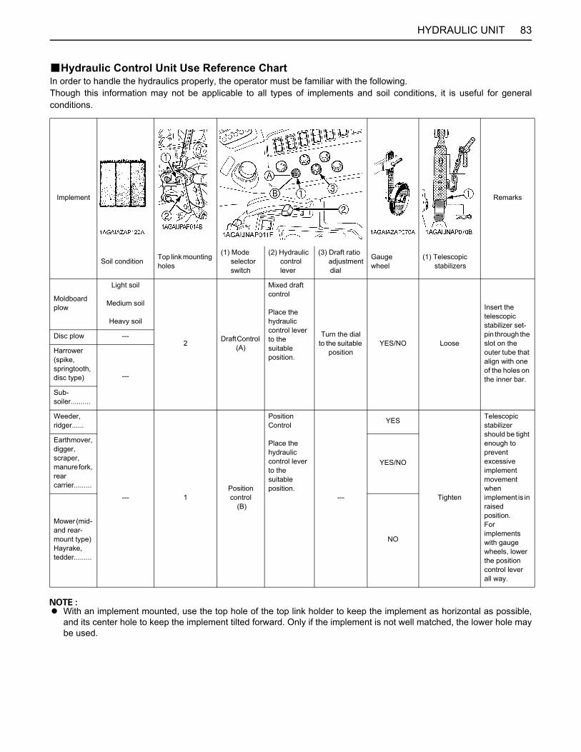
83HYDRAULIC UNIT
BHydraulic Control Unit Use Reference ChartIn order to handle the hydraulics properly, the operator must be familiar with the following.Though this information may not be applicable to all types of implements and soil conditions, it is useful for generalconditions.
A With an implement mounted, use the top hole of the top link holder to keep the implement as horizontal as possible,and its center hole to keep the implement tilted forward. Only if the implement is not well matched, the lower hole maybe used.
Implement Remarks
Soil condition Top link mounting holes
(1) Mode selector switch
(2) Hydraulic control lever
(3) Draft ratio adjustment dial
Gaugewheel
(1) Telescopic stabilizers
Moldboard plow
Light soil
Medium soil
Heavy soil
2 Draft Control (A)
Mixed draft control
Place the hydraulic control lever to the suitable position.
Turn the dial to the suitable
positionYES/NO Loose
Insert the telescopic stabilizer set-pin through the slot on the outer tube that align with one of the holes on the inner bar.
Disc plow ---
Harrower (spike, springtooth, disc type) ---
Sub-soiler..........
Weeder, ridger......
--- 1Position control
(B)
Position Control
Place the hydraulic control lever to the suitable position.
---
YES
Tighten
Telescopic stabilizer should be tight enough to prevent excessive implement movement when implement is in raised position.For implements with gauge wheels, lower the position control lever all way.
Earthmover, digger, scraper, manure fork, rear carrier.........
YES/NO
Mower (mid- and rear-mount type) Hayrake, tedder.........
NO
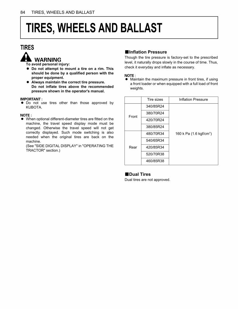
84 TIRES, WHEELS AND BALLAST
TIRES, WHEELS AND BALLAST
TIRESTo avoid personal injury:A Do not attempt to mount a tire on a rim. This
should be done by a qualified person with theproper equipment.
A Always maintain the correct tire pressure.Do not inflate tires above the recommendedpressure shown in the operator's manual.
A Do not use tires other than those approved byKUBOTA.
A When optional different-diameter tires are fitted on themachine, the travel speed display mode must bechanged. Otherwise the travel speed will not getcorrectly displayed. Such mode switching is alsoneeded when the original tires are back on themachine.(See "SIDE DIGITAL DISPLAY" in "OPERATING THETRACTOR" section.)
BInflation PressureThough the tire pressure is factory-set to the prescribedlevel, it naturally drops slowly in the course of time. Thus,check it everyday and inflate as necessary.
A Maintain the maximum pressure in front tires, if usinga front loader or when equipped with a full load of frontweights.
BDual TiresDual tires are not approved.
Tire sizes Inflation Pressure
Front
340/85R24
160 k Pa (1.6 kgf/cm )
380/70R24
420/70R24
380/85R24
Rear
480/70R34
540/65R34
420/85R34
520/70R38
460/85R38

85TIRES, WHEELS AND BALLAST
WHEEL ADJUSTMENT
To avoid personal injury:A When working on slopes or when working with
trailer, set the wheel tread as wide as practicalfor maximum stability.
A Support tractor securely on stands beforeremoving a wheel.
A Do not work under any hydraulically supporteddevices. They can settle, suddenly leak down,or be accidentally lowered. If necessary to workunder tractor or any machine elements forservicing or adjustment, securely support themwith stands or suitable blocking beforehand.
A Never operate tractor with a loose rim, wheel,or axle.
BFront Wheels (with four wheel drive)Front tread width can be adjusted as shown with thestandard equipped tires.To change the tread width1. Remove the wheel rim and disk mounting bolts.2. Change the position of the rim and tire to the desired
position, and tighten the bolts.3. Adjust the toe-in [2 to 8mm]
See "Adjusting Toe-in" in "EVERY 200 HOURS" in"PERIODIC SERVICE" section.
A Need to limit turning angle depended on the tire sizeand tread.
A Always attach wheels as shown in the drawing.A If not attached as illustrated, transmission parts may
be damaged.
A When re-fitting or adjusting a wheel, tighten the boltsto the following torques then recheck after driving thetractor 200m (200 yards) and 10 times of shuttlemovement by 5 m (5 yards), and thereafter accordingto service interval. (See "MAINTENANCE" section.)
A Wheels with beveled or tapered holes: Use thetapered side of lug nut.
To avoid personal injury:A Before jacking up the tractor, park it on a firm
and level ground and chock the rear wheels.A Fix the front axle to keep it from swinging.A Select jacks that withstand the machine weight
and set them up as shown below.
(1) 260 to 304 N-m (26.5 to 31 kgf-m)
(1) Jack point
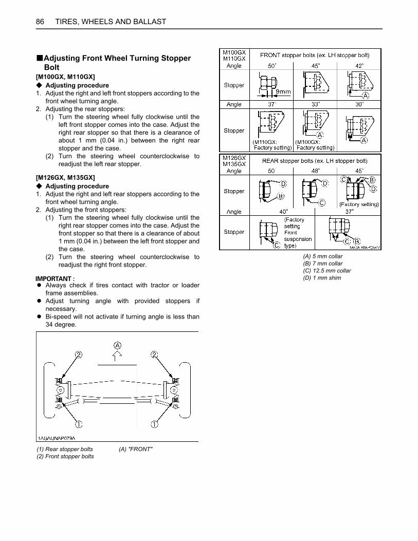
TIRES, WHEELS AND BALLAST86
BAdjusting Front Wheel Turning Stopper Bolt
[M100GX, M110GX]C Adjusting procedure1. Adjust the right and left front stoppers according to the
front wheel turning angle.2. Adjusting the rear stoppers:
(1) Turn the steering wheel fully clockwise until theleft front stopper comes into the case. Adjust theright rear stopper so that there is a clearance ofabout 1 mm (0.04 in.) between the right rearstopper and the case.
(2) Turn the steering wheel counterclockwise toreadjust the left rear stopper.
[M126GX, M135GX]C Adjusting procedure1. Adjust the right and left rear stoppers according to the
front wheel turning angle.2. Adjusting the front stoppers:
(1) Turn the steering wheel fully clockwise until theright rear stopper comes into the case. Adjust thefront stopper so that there is a clearance of about1 mm (0.04 in.) between the left front stopper andthe case.
(2) Turn the steering wheel counterclockwise toreadjust the right front stopper.
A Always check if tires contact with tractor or loaderframe assemblies.
A Adjust turning angle with provided stoppers ifnecessary.
A Bi-speed will not activate if turning angle is less than34 degree.
(1) Rear stopper bolts (2) Front stopper bolts
(A) "FRONT"
(A) 5 mm collar(B) 7 mm collar(C) 12.5 mm collar(D) 1 mm shim
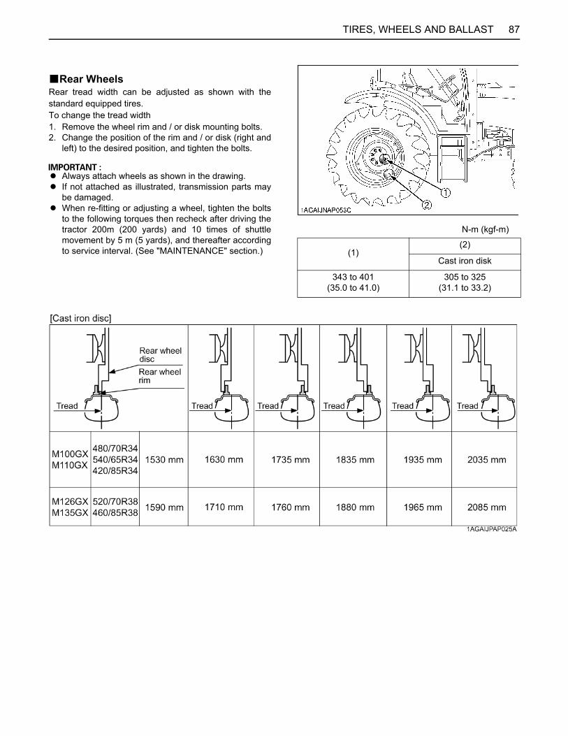
87TIRES, WHEELS AND BALLAST
BRear WheelsRear tread width can be adjusted as shown with thestandard equipped tires.To change the tread width1. Remove the wheel rim and / or disk mounting bolts.2. Change the position of the rim and / or disk (right and
left) to the desired position, and tighten the bolts.
A Always attach wheels as shown in the drawing.A If not attached as illustrated, transmission parts may
be damaged.A When re-fitting or adjusting a wheel, tighten the bolts
to the following torques then recheck after driving thetractor 200m (200 yards) and 10 times of shuttlemovement by 5 m (5 yards), and thereafter accordingto service interval. (See "MAINTENANCE" section.)
N-m (kgf-m)
(1)(2)
Cast iron disk
343 to 401(35.0 to 41.0)
305 to 325(31.1 to 33.2)

TIRES, WHEELS AND BALLAST88
To avoid personal injury:A Before jacking up the tractor, park it on a firm
and level ground and chock the front wheels.A Fix the front axle to keep it from swinging.A Select a jack that withstands the machine
weight and set it up as shown below.
BALLAST
To avoid personal injury:A Additional ballast will be needed for
transporting heavy implements. When theimplement is raised, drive slowly over roughground, regardless of how much ballast isused.
A Do not fill the front wheels with liquid tomaintain steering control.
BFront BallastAdd weights if needed for stability and improve traction.Heavy pulling and heavy rear mounted implements tendto lift front wheels.Add enough ballast to maintain steering control andprevent tip over. Remove weight when no longer needed.
C Front End Weights (option)The front end weights can be attached to the bumper.See your implement operator's manual for requirednumber of weights or consult your local KUBOTA Dealerto use.
A Do not overload tires.A Add no more weight than indicated in chart.
(1) Jack point
(1) Front end weights(2) Bumper
Maximum weight 45 kg x 12 pieces
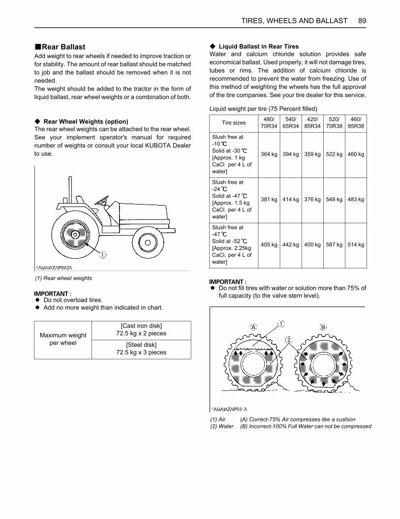
89TIRES, WHEELS AND BALLAST
BRear BallastAdd weight to rear wheels if needed to improve traction orfor stability. The amount of rear ballast should be matchedto job and the ballast should be removed when it is notneeded.The weight should be added to the tractor in the form ofliquid ballast, rear wheel weights or a combination of both.
C Rear Wheel Weights (option)The rear wheel weights can be attached to the rear wheel.See your implement operator's manual for requirednumber of weights or consult your local KUBOTA Dealerto use.
A Do not overload tires.A Add no more weight than indicated in chart.
C Liquid Ballast in Rear TiresWater and calcium chloride solution provides safeeconomical ballast. Used properly, it will not damage tires,tubes or rims. The addition of calcium chloride isrecommended to prevent the water from freezing. Use ofthis method of weighting the wheels has the full approvalof the tire companies. See your tire dealer for this service.
Liquid weight per tire (75 Percent filled)
A Do not fill tires with water or solution more than 75% offull capacity (to the valve stem level).
(1) Rear wheel weights
Maximum weight per wheel
[Cast iron disk]72.5 kg x 2 pieces
[Steel disk]72.5 kg x 3 pieces
Tire sizes 480/70R34
540/65R34
420/85R34
520/70R38
460/85R38
Slush free at -10Solid at -30[Approx. 1 kg CaCl per 4 L of water]
364 kg 394 kg 359 kg 522 kg 460 kg
Slush free at -24Solid at -47[Approx. 1.5 kg CaCl per 4 L of water]
381 kg 414 kg 376 kg 548 kg 483 kg
Slush free at -47Solid at -52 [Approx. 2.25kg CaCl per 4 L of water]
405 kg 442 kg 400 kg 587 kg 514 kg
(1) Air(2) Water
(A) Correct-75% Air compresses like a cushion (B) Incorrect-100% Full Water can not be compressed
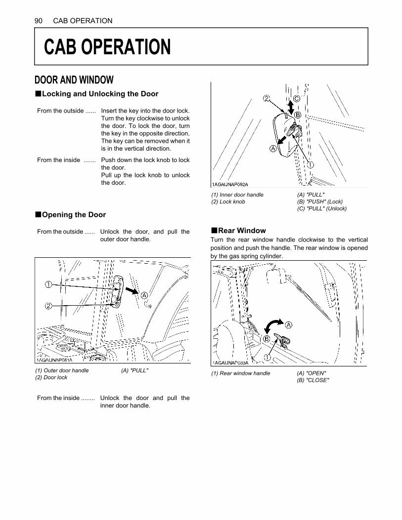
90 CAB OPERATION
CAB OPERATION
DOOR AND WINDOWBLocking and Unlocking the DoorBOpening the Door
BRear WindowTurn the rear window handle clockwise to the verticalposition and push the handle. The rear window is openedby the gas spring cylinder.
From the outside ...... Insert the key into the door lock.Turn the key clockwise to unlockthe door. To lock the door, turnthe key in the opposite direction.The key can be removed when itis in the vertical direction.
From the inside ....... Push down the lock knob to lockthe door.Pull up the lock knob to unlockthe door.
From the outside ...... Unlock the door, and pull theouter door handle.
(1) Outer door handle(2) Door lock
(A) "PULL"
From the inside ........ Unlock the door and pull theinner door handle.
(1) Inner door handle(2) Lock knob
(A) "PULL"(B) "PUSH" (Lock)(C) "PULL" (Unlock)
(1) Rear window handle (A) "OPEN"(B) "CLOSE"
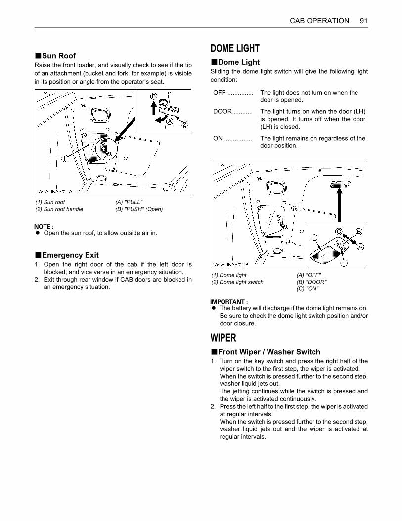
91CAB OPERATION
BSun RoofRaise the front loader, and visually check to see if the tipof an attachment (bucket and fork, for example) is visiblein its position or angle from the operator’s seat.
A Open the sun roof, to allow outside air in.
BEmergency Exit1. Open the right door of the cab if the left door is
blocked, and vice versa in an emergency situation.2. Exit through rear window if CAB doors are blocked in
an emergency situation.
DOME LIGHTBDome LightSliding the dome light switch will give the following lightcondition:
A The battery will discharge if the dome light remains on.Be sure to check the dome light switch position and/ordoor closure.
WIPERBFront Wiper / Washer Switch1. Turn on the key switch and press the right half of the
wiper switch to the first step, the wiper is activated.When the switch is pressed further to the second step,washer liquid jets out.The jetting continues while the switch is pressed andthe wiper is activated continuously.
2. Press the left half to the first step, the wiper is activatedat regular intervals.When the switch is pressed further to the second step,washer liquid jets out and the wiper is activated atregular intervals.
(1) Sun roof(2) Sun roof handle
(A) "PULL"(B) "PUSH" (Open)
OFF ............... The light does not turn on when the door is opened.
DOOR ........... The light turns on when the door (LH)is opened. It turns off when the door(LH) is closed.
ON ................ The light remains on regardless of thedoor position.
(1) Dome light(2) Dome light switch
(A) "OFF"(B) "DOOR"(C) "ON"

CAB OPERATION92
BRear Wiper / Washer Switch1. Turn on the key switch and press the right half of the
wiper switch to the first step, the wiper is activated.When the switch is pressed further to the second step,washer liquid jets out.The jetting continues while the switch is pressed andthe wiper is activated continuously.
2. Press the left half of the wiper / washer switch, washerliquid only jets out.
A Do not activate the wipers when the windows are dry,they may be scratched.Be sure to jet washer liquid first and then activate thewipers.
BUsing the Wipers in Cold Season1. While not used in cold season, keep the wiper blades
off the windshield to prevent them from being stuckwith ice.
2. If the windshield is covered with snow, scrape it off thewindshield before using the wipers.
3. If the wiper blades are stuck on the windshield with iceand fail to move, be sure to turn the main key switch to"OFF" and remove the ice off the blades. Then placethe main key switch back to "ON".
4. When commercially available cold-season wiperblades are used, make sure their size is the same asor smaller than that of the standard ones.
A In cold season, the wiper blades and the wiper motormight get overloaded causing damage. To avoid this,be sure to take the above precautions.
AIR CONDITIONERBAirflowAir in the CAB and fresh air introduced into the CAB flowas shown below. Adjust the seven air ports to obtain thedesired condition.
(1) Front wiper / washer switch(2) Rear wiper / washer switch
(1) Control panel(2) Defroster air outlets(3) Dashboard air outlets(4) Inner air filter
(A) Inner air recirculation
(1) Fresh air filter (A) "FRESH AIR INLET"
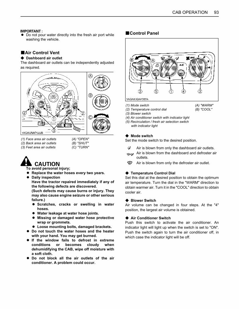
93CAB OPERATION
A Do not pour water directly into the fresh air port whilewashing the vehicle.
BAir Control VentC Dashboard air outletThe dashboard air outlets can be independently adjustedas required.
To avoid personal injury;A Replace the water hoses every two years.A Daily inspection
Have the tractor repaired immediately if any ofthe following defects are discovered.(Such defects may cause burns or injury. Theymay also cause engine seizure or other seriousfailure.)A Scratches, cracks or swelling in water
hoses.A Water leakage at water hose joints.A Missing or damaged water hose protective
wrap or grommets.A Loose mounting bolts, damaged brackets.
A Do not touch the water hoses and the heaterwith your hand. You may get burned.
A If the window fails to defrost in extremeconditions or becomes cloudy whendehumidifying the CAB, wipe off moisture witha soft cloth.
A Do not block all the air outlets of the airconditioner. A problem could occur.
BControl Panel
C Mode switchSet the mode switch to the desired position.
C Temperature Control DialSet this dial at the desired position to obtain the optimumair temperature. Turn the dial in the "WARM" direction toobtain warmer air. Turn it in the "COOL" direction to obtaincooler air.
C Blower SwitchAir volume can be changed in four steps. At the "4"position, the largest air volume is obtained.
C Air Conditioner SwitchPush this switch to activate the air conditioner. Anindicator light will light up when the switch is set to "ON".Push the switch again to turn the air conditioner off, inwhich case the indicator light will be off.
(1) Face area air outlets(2) Back area air outlets(3) Feet area air outlets
(A) "OPEN"(B) "SHUT"(C) "TURN"
(1) Mode switch(2) Temperature control dial(3) Blower switch(4) Air conditioner switch with indicator light(5) Recirculation / fresh air selection switch with indicator light
(A) "WARM"(B) "COOL"
Air is blown from only the dashboard air outlets.Air is blown from the dashboard and defroster air outlets.Air is blown from only the defroster air outlet.
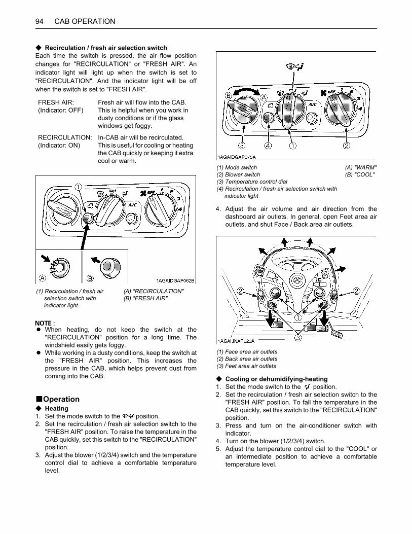
CAB OPERATION94
C Recirculation / fresh air selection switchEach time the switch is pressed, the air flow positionchanges for "RECIRCULATION" or "FRESH AIR". Anindicator light will light up when the switch is set to"RECIRCULATION". And the indicator light will be offwhen the switch is set to "FRESH AIR".
A When heating, do not keep the switch at the"RECIRCULATION" position for a long time. Thewindshield easily gets foggy.
A While working in a dusty conditions, keep the switch atthe "FRESH AIR" position. This increases thepressure in the CAB, which helps prevent dust fromcoming into the CAB.
BOperationC Heating1. Set the mode switch to the position.2. Set the recirculation / fresh air selection switch to the
"FRESH AIR" position. To raise the temperature in theCAB quickly, set this switch to the "RECIRCULATION"position.
3. Adjust the blower (1/2/3/4) switch and the temperaturecontrol dial to achieve a comfortable temperaturelevel.
4. Adjust the air volume and air direction from thedashboard air outlets. In general, open Feet area airoutlets, and shut Face / Back area air outlets.
C Cooling or dehumidifying-heating1. Set the mode switch to the position.2. Set the recirculation / fresh air selection switch to the
"FRESH AIR" position. To fall the temperature in theCAB quickly, set this switch to the "RECIRCULATION"position.
3. Press and turn on the air-conditioner switch withindicator.
4. Turn on the blower (1/2/3/4) switch.5. Adjust the temperature control dial to the "COOL" or
an intermediate position to achieve a comfortabletemperature level.
FRESH AIR:(Indicator: OFF)
Fresh air will flow into the CAB. This is helpful when you work in dusty conditions or if the glass windows get foggy.
RECIRCULATION:(Indicator: ON)
In-CAB air will be recirculated. This is useful for cooling or heating the CAB quickly or keeping it extra cool or warm.
(1) Recirculation / fresh air selection switch with indicator light
(A) "RECIRCULATION"(B) "FRESH AIR"
(1) Mode switch(2) Blower switch(3) Temperature control dial(4) Recirculation / fresh air selection switch with indicator light
(A) "WARM"(B) "COOL"
(1) Face area air outlets(2) Back area air outlets(3) Feet area air outlets

95CAB OPERATION
A In summer when the heater is not used, keep thetemperature control dial at the max "COOL" (end ofcounterclockwise) position. Otherwise, hot air willraise the temperature in the CAB.
6. Adjust the air volume and air direction from thedashboard air outlets. In general, the air volume fromFace area air outlets is adjusted to increase, and theair volume from Feet / Back area air outlets is adjustedto decrease.
C Defrosting or demistingTo defrost or demist the windshield, take the followingsteps.1. Set the mode switch to the position.2. Set the recirculation / fresh air selection switch to the
"FRESH AIR" position.3. Set the blower switch and the temperature control dial
to the "4" and max "WARM" (end of clockwise)positions, respectively.
A If you set the mode switch to position, air will notcome out from the dashboard air outlets.
(1) Mode switch(2) Temperature control dial(3) Blower switch(4) Air conditioner switch with indicator light(5) Recirculation / fresh air selection switch with indicator light
(A) "WARM"(B) "COOL"
(1) Face area air outlets(2) Back area air outlets(3) Feet area air outlets
(1) Mode switch(2) Temperature control dial(3) Blower switch(4) Recirculation / fresh air selection switch with indicator light
(A) "WARM"(B) "COOL"
(1) Defroster air outlet
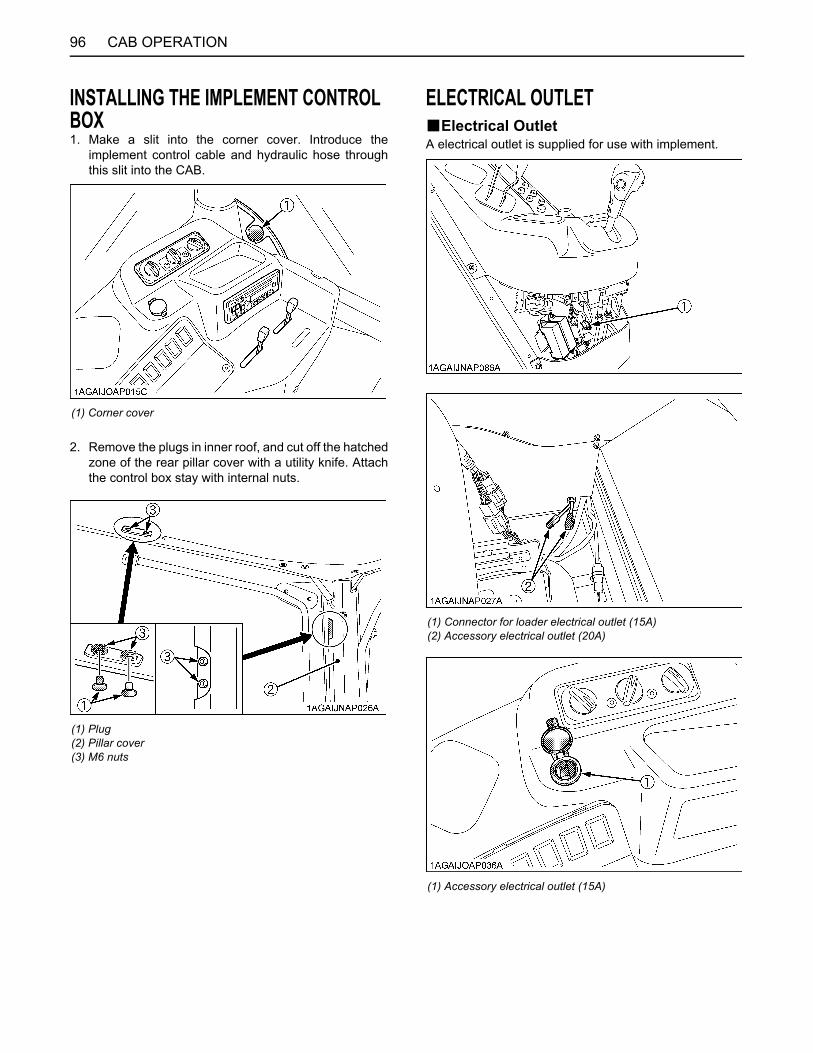
CAB OPERATION96
INSTALLING THE IMPLEMENT CONTROL BOX1. Make a slit into the corner cover. Introduce the
implement control cable and hydraulic hose throughthis slit into the CAB.
2. Remove the plugs in inner roof, and cut off the hatchedzone of the rear pillar cover with a utility knife. Attachthe control box stay with internal nuts.
ELECTRICAL OUTLETBElectrical OutletA electrical outlet is supplied for use with implement.
(1) Corner cover
(1) Plug(2) Pillar cover(3) M6 nuts
(1) Connector for loader electrical outlet (15A)(2) Accessory electrical outlet (20A)
(1) Accessory electrical outlet (15A)
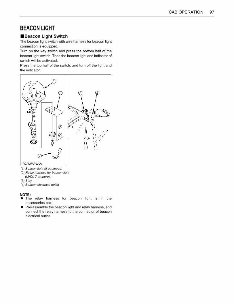
97CAB OPERATION
BEACON LIGHTBBeacon Light SwitchThe beacon light switch with wire harness for beacon lightconnection is equipped.Turn on the key switch and press the bottom half of thebeacon light switch. Then the beacon light and indicator ofswitch will be activated.Press the top half of the switch, and turn off the light andthe indicator.
A The relay harness for beacon light is in theaccessories box.
A Pre-assemble the beacon light and relay harness, andconnect the relay harness to the connector of beaconelectrical outlet.
(1) Beacon light (if equipped)(2) Relay harness for beacon light (MAX. 7 amperes)(3) Stay(4) Beacon electrical outlet

98 MAINTENANCE
MAINTENANCE
SERVICE INTERVALSNo. ItemsIndication on hour meter
Interval Ref.page50 100 150 200 250 300 350 400 450 500 550 600 650 700
1 Engine start system Check every50 Hr 110
2 Wheel bolt torque Check every50 Hr 111
3 Tie-rod dust cover Check every50 Hr 111 *4
4 Battery condition Check every100 Hr 116 *5
5 Greasing every100 Hr 111
6 Fan belt [M100GX, M110GX] Adjust every
100 Hr 114
7 Brake pedal Adjust every100 Hr 115
8 Parking brake lever Adjust every100 Hr 115
9Air cleaner element
Primary element
Clean every100 Hr 113 *1
Replace every1 year 131 *2
Second-ary element
Replace every1 year 131
10 Fuel line
Check every100 Hr 114
Replace every2 years 133 *4
11 Toe-in Adjust every200 Hr 120
12 Fuel tank water Drain every200 Hr 120
13 Oil cooler line
Check every200 Hr 119
Replace every2 years 133 *4
14 Power steering oil line
Check every200 Hr 119
Replace every2 years 133 *4
15 Radiator hose and clamp
Check every200 Hr 117
Replace every2 years 133

99MAINTENANCE
16 Intake air line
Check every200 Hr 119
Replace every2 years 133 *3
17 Hydraulic oil filter Replace every300 Hr 122
18 Engine oil Change every400 Hr 123
19 Engine oil filter Replace every400 Hr 124
20 Water separator Clean every400 Hr 126
21 Pre-Fuel filter[M126GX, M135GX] Clean every
400 Hr 126
22 Fuel filter[M100GX, M110GX] Replace every
400 Hr 126
23Fan / Air-conditioner belt [M126GX, M135GX]
Adjust every400 Hr 124
24 Fuel solenoid pump [M126GX, M135GX] Clean every
400 Hr 127
25 Transmission fluid Change every600 Hr 128
26 Front differential case oil Change every
600 Hr 129
27 Front axle gear case oil Change every
600 Hr 129
28 Front axle pivot Adjust every600 Hr 130
29 King-pin pivot Adjust every600 Hr 130
30 Fuel filter[M126GX, M135GX] Replace every
800 Hr 130
31 Engine valve clearance Adjust every
800 Hr 130 *4
32 Fuel injector nozzle tip Clean every
1500 Hr 130 *4
33 EGR cooler CheckClean
every1500 Hr 130 *4
34 Accumulator [Front suspension type] Check every
1500 Hr 130 *4
35 Turbo charger Check every3000 Hr 130 *4
36 Supply pump Check every3000 Hr 130 *4
37 EGR system CheckClean
every3000 Hr 131 *4
38 DPF muffler Clean every3000 Hr 131 *4
39 Intake air heater[M100GX, M110GX] Check every
3000 Hr 131 *4
No. ItemsIndication on hour meter
Interval Ref.page50 100 150 200 250 300 350 400 450 500 550 600 650 700
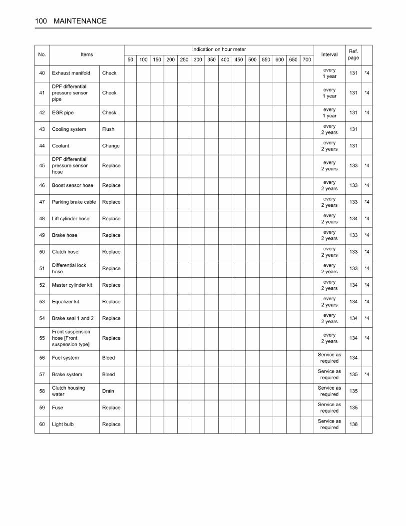
100 MAINTENANCE
40 Exhaust manifold Check every1 year 131 *4
41DPF differential pressure sensor pipe
Check every1 year 131 *4
42 EGR pipe Check every1 year 131 *4
43 Cooling system Flush every2 years 131
44 Coolant Change every2 years 131
45DPF differential pressure sensor hose
Replace every2 years 133 *4
46 Boost sensor hose Replace every2 years 133 *4
47 Parking brake cable Replace every2 years 133 *4
48 Lift cylinder hose Replace every2 years 134 *4
49 Brake hose Replace every2 years 133 *4
50 Clutch hose Replace every2 years 133 *4
51 Differential lock hose Replace every
2 years 133 *4
52 Master cylinder kit Replace every2 years 134 *4
53 Equalizer kit Replace every2 years 134 *4
54 Brake seal 1 and 2 Replace every2 years 134 *4
55Front suspension hose [Front suspension type]
Replace every2 years 134 *4
56 Fuel system Bleed Service asrequired 134
57 Brake system Bleed Service asrequired 135 *4
58 Clutch housing water Drain Service as
required 135
59 Fuse Replace Service asrequired 135
60 Light bulb Replace Service asrequired 138
No. ItemsIndication on hour meter
Interval Ref.page50 100 150 200 250 300 350 400 450 500 550 600 650 700

101MAINTENANCE
A The jobs indicated by must be done after the first 50 hours of operation.*1 Air cleaner should be cleaned more often in dusty conditions than in normal conditions.*2 Every year or every 6 times of cleaning.*3 Replace only if necessary.*4 Consult your local KUBOTA Dealer for this service.*5 When the battery is used for less than 100 hours per year, check the battery condition by reading the indicator annually.
No. ItemsIndication on hour meter
Interval Ref.page50 100 150 200 250 300 350 400 450 500 550 600 650 700
1 Inner air filter Clean every200 Hr 121
2 Fresh air filter Clean every200 Hr 121
3Air conditioner drive belt[M100GX, M110GX]
Adjust every200 Hr 122
4 Air conditioner pipes and hoses
Check every1 year 131
Replace every2 years 134 *4
5 CAB isolation cushion Check every
1 year 131
6 Washer liquid Add Service asrequired 139
7 Refrigerant (gas) Check Service asrequired 139
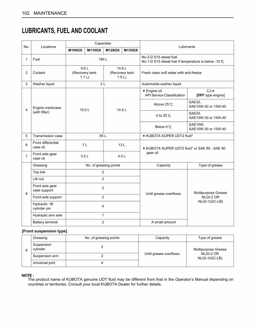
102 MAINTENANCE
LUBRICANTS, FUEL AND COOLANT
[Front suspension type]
The product name of KUBOTA genuine UDT fluid may be different from that in the Operator’s Manual depending oncountries or territories. Consult your local KUBOTA Dealer for further details.
No. LocationsCapacities
LubricantsM100GX M110GX M126GX M135GX
1 Fuel 190 L No.2-D S15 diesel fuelNo.1-D S15 diesel fuel if temperature is below -10
2 Coolant9.6 L
(Recovery tank:1.1 L)
14.6 L (Recovery tank:
1.5 L)Fresh clean soft water with anti-freeze
3 Washer liquid 2 L Automobile washer liquid
4 Engine crankcase(with filter) 10.5 L 14.6 L
Engine oil: API Service Classification
CJ-4[DPF type engine]
Above 25 SAE30,SAE10W-30 or 15W-40
0 to 25 SAE20,SAE10W-30 or 15W-40
Below 0 SAE10W,SAE10W-30 or 15W-40
5 Transmission case 65 L KUBOTA SUPER UDT2 fluid*
6 Front differential case oil 7 L 13 L
KUBOTA SUPER UDT2 fluid* or SAE 80 - SAE 90 gear oil
7 Front axle gear case oil 3.5 L 4.5 L
8
Greasing No. of greasing points Capacity Type of grease
Top link 2
Until grease overflows. Multipurpose GreaseNLGI-2 OR
NLGI-1(GC-LB)
Lift rod 2
Front axle gear case support 2
Front axle support 2
Hydraulic lift cylinder pin 4
Hydraulic arm axle 1
Battery terminal 2 A small amount
8
Greasing No. of greasing points Capacity Type of grease
Suspension cylinder 2
Until grease overflows.Multipurpose Grease
NLGI-2 OR NLGI-1(GC-LB)Suspension arm 2
Universal joint 4
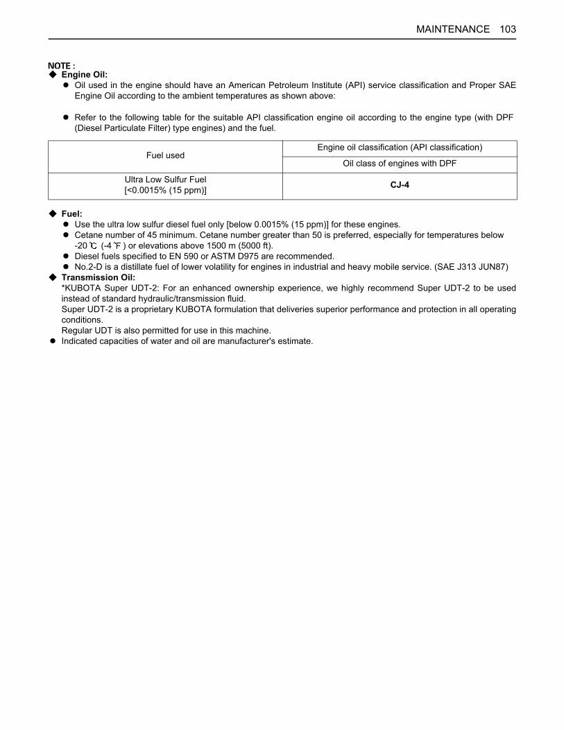
103MAINTENANCE
C Engine Oil:A Oil used in the engine should have an American Petroleum Institute (API) service classification and Proper SAE
Engine Oil according to the ambient temperatures as shown above:
C Fuel:A Use the ultra low sulfur diesel fuel only [below 0.0015% (15 ppm)] for these engines.A Cetane number of 45 minimum. Cetane number greater than 50 is preferred, especially for temperatures below
-20 (-4 ) or elevations above 1500 m (5000 ft).A Diesel fuels specified to EN 590 or ASTM D975 are recommended.A No.2-D is a distillate fuel of lower volatility for engines in industrial and heavy mobile service. (SAE J313 JUN87)
C Transmission Oil:*KUBOTA Super UDT-2: For an enhanced ownership experience, we highly recommend Super UDT-2 to be usedinstead of standard hydraulic/transmission fluid.Super UDT-2 is a proprietary KUBOTA formulation that deliveries superior performance and protection in all operatingconditions.Regular UDT is also permitted for use in this machine.
A Indicated capacities of water and oil are manufacturer's estimate.
A Refer to the following table for the suitable API classification engine oil according to the engine type (with DPF(Diesel Particulate Filter) type engines) and the fuel.
Fuel usedEngine oil classification (API classification)
Oil class of engines with DPF
Ultra Low Sulfur Fuel[<0.0015% (15 ppm)] CJ-4

104 PERIODIC SERVICE
PERIODIC SERVICE
To avoid personal injury:A Do not work under any hydraulically supported
devices. They can settle, suddenly leak down,or be accidentally lowered. If necessary to workunder tractor or any machine elements forservicing or adjustment, securely support themwith stands or suitable blocking beforehand.
HOW TO OPEN THE HOOD
To avoid personal injury from contact with movingparts;A Never open the hood or engine side cover while
the engine is running.A Do not touch muffler or exhaust pipes while
they are hot; Severe burns could result.A Hold the hood with other hand while unlocking
release lever.
BHoodTo open the hood, hold the hood and pull the release leverand open the hood.
A To close the hood, pull down on the strap and push thehood into position using both hands.
BSide CoverRemove the bolts as shown below.
DAILY CHECKFor your own safety and maximum service life of themachine, make a thorough daily inspection beforeoperating the machine to start the engine.
To avoid personal injury:Take the following precautions when checking thetractor.A Park the machine on firm and level ground.A Set the parking brake.A Lower the implement to the ground.A All residual pressure of the hydraulic system
released.A Stop the engine and remove the key.
(1) Release lever(2) Hood
(A) "PULL"
(1) Strap
(1) Side cover(2) Bolt
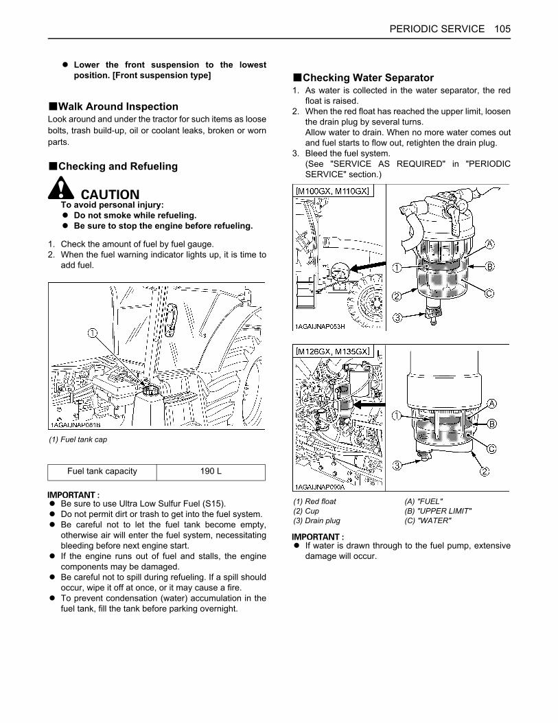
105PERIODIC SERVICE
A Lower the front suspension to the lowestposition. [Front suspension type]
BWalk Around InspectionLook around and under the tractor for such items as loosebolts, trash build-up, oil or coolant leaks, broken or wornparts.
BChecking and Refueling
To avoid personal injury:A Do not smoke while refueling.A Be sure to stop the engine before refueling.
1. Check the amount of fuel by fuel gauge.2. When the fuel warning indicator lights up, it is time to
add fuel.
A Be sure to use Ultra Low Sulfur Fuel (S15).A Do not permit dirt or trash to get into the fuel system.A Be careful not to let the fuel tank become empty,
otherwise air will enter the fuel system, necessitatingbleeding before next engine start.
A If the engine runs out of fuel and stalls, the enginecomponents may be damaged.
A Be careful not to spill during refueling. If a spill shouldoccur, wipe it off at once, or it may cause a fire.
A To prevent condensation (water) accumulation in thefuel tank, fill the tank before parking overnight.
BChecking Water Separator1. As water is collected in the water separator, the red
float is raised.2. When the red float has reached the upper limit, loosen
the drain plug by several turns.Allow water to drain. When no more water comes outand fuel starts to flow out, retighten the drain plug.
3. Bleed the fuel system.(See "SERVICE AS REQUIRED" in "PERIODICSERVICE" section.)
A If water is drawn through to the fuel pump, extensivedamage will occur.
(1) Fuel tank cap
Fuel tank capacity 190 L
(1) Red float(2) Cup(3) Drain plug
(A) "FUEL"(B) "UPPER LIMIT"(C) "WATER"
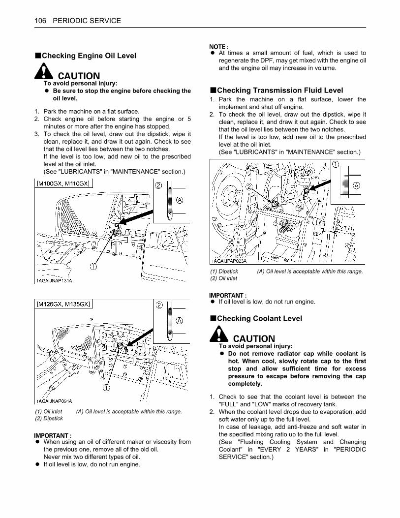
PERIODIC SERVICE106
BChecking Engine Oil Level
To avoid personal injury:A Be sure to stop the engine before checking the
oil level.
1. Park the machine on a flat surface.2. Check engine oil before starting the engine or 5
minutes or more after the engine has stopped.3. To check the oil level, draw out the dipstick, wipe it
clean, replace it, and draw it out again. Check to seethat the oil level lies between the two notches.If the level is too low, add new oil to the prescribedlevel at the oil inlet.(See "LUBRICANTS" in "MAINTENANCE" section.)
A When using an oil of different maker or viscosity fromthe previous one, remove all of the old oil.Never mix two different types of oil.
A If oil level is low, do not run engine.
A At times a small amount of fuel, which is used toregenerate the DPF, may get mixed with the engine oiland the engine oil may increase in volume.
BChecking Transmission Fluid Level1. Park the machine on a flat surface, lower the
implement and shut off engine.2. To check the oil level, draw out the dipstick, wipe it
clean, replace it, and draw it out again. Check to seethat the oil level lies between the two notches.If the level is too low, add new oil to the prescribedlevel at the oil inlet.(See "LUBRICANTS" in "MAINTENANCE" section.)
A If oil level is low, do not run engine.
BChecking Coolant Level
To avoid personal injury:A Do not remove radiator cap while coolant is
hot. When cool, slowly rotate cap to the firststop and allow sufficient time for excesspressure to escape before removing the capcompletely.
1. Check to see that the coolant level is between the"FULL" and "LOW" marks of recovery tank.
2. When the coolant level drops due to evaporation, addsoft water only up to the full level.In case of leakage, add anti-freeze and soft water inthe specified mixing ratio up to the full level.(See "Flushing Cooling System and ChangingCoolant" in "EVERY 2 YEARS" in "PERIODICSERVICE" section.)
(1) Oil inlet(2) Dipstick
(A) Oil level is acceptable within this range.
(1) Dipstick(2) Oil inlet
(A) Oil level is acceptable within this range.
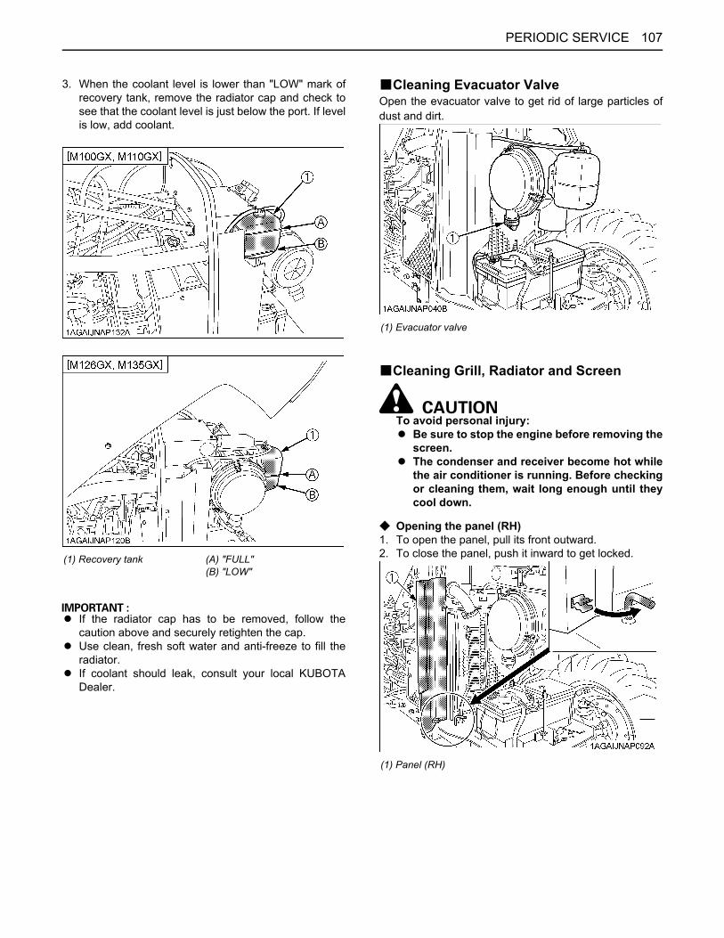
107PERIODIC SERVICE
3. When the coolant level is lower than "LOW" mark ofrecovery tank, remove the radiator cap and check tosee that the coolant level is just below the port. If levelis low, add coolant.
A If the radiator cap has to be removed, follow thecaution above and securely retighten the cap.
A Use clean, fresh soft water and anti-freeze to fill theradiator.
A If coolant should leak, consult your local KUBOTADealer.
BCleaning Evacuator ValveOpen the evacuator valve to get rid of large particles ofdust and dirt.
BCleaning Grill, Radiator and Screen
To avoid personal injury:A Be sure to stop the engine before removing the
screen.A The condenser and receiver become hot while
the air conditioner is running. Before checkingor cleaning them, wait long enough until theycool down.
C Opening the panel (RH)1. To open the panel, pull its front outward.2. To close the panel, push it inward to get locked.(1) Recovery tank (A) "FULL"
(B) "LOW"
(1) Evacuator valve
(1) Panel (RH)
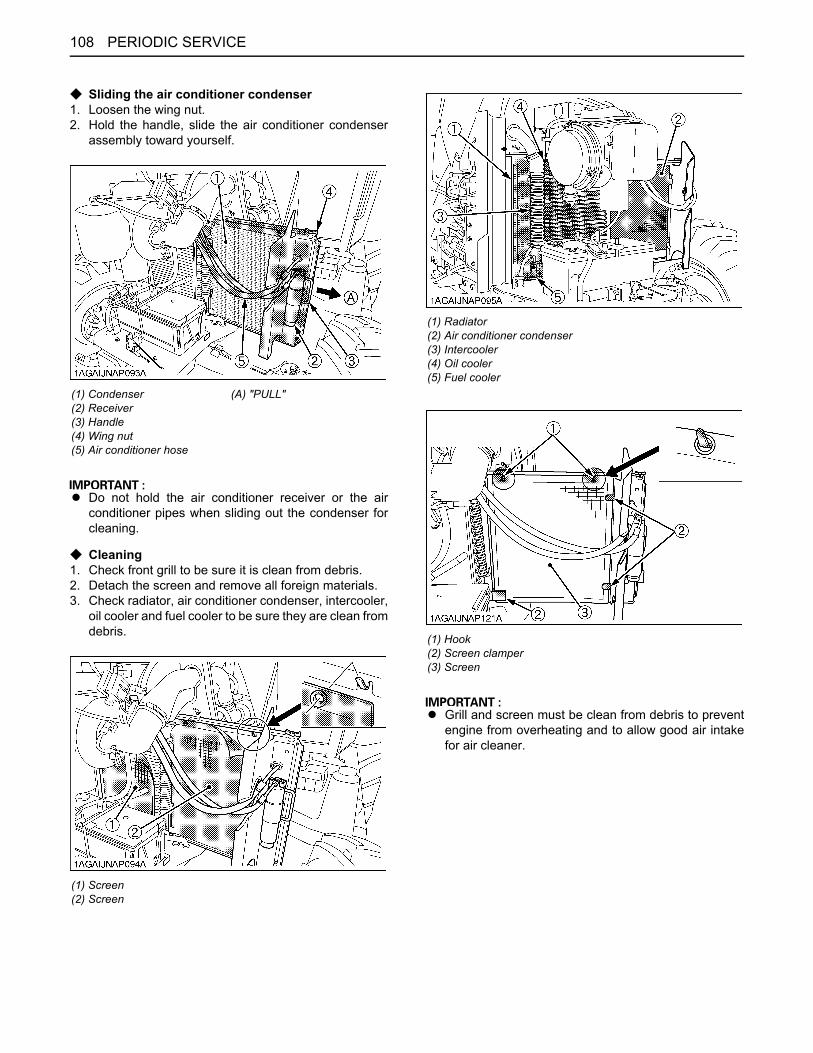
PERIODIC SERVICE108
C Sliding the air conditioner condenser1. Loosen the wing nut.2. Hold the handle, slide the air conditioner condenser
assembly toward yourself.
A Do not hold the air conditioner receiver or the airconditioner pipes when sliding out the condenser forcleaning.
C Cleaning1. Check front grill to be sure it is clean from debris.2. Detach the screen and remove all foreign materials.3. Check radiator, air conditioner condenser, intercooler,
oil cooler and fuel cooler to be sure they are clean fromdebris.
A Grill and screen must be clean from debris to preventengine from overheating and to allow good air intakefor air cleaner.
(1) Condenser(2) Receiver(3) Handle(4) Wing nut(5) Air conditioner hose
(A) "PULL"
(1) Screen(2) Screen
(1) Radiator(2) Air conditioner condenser(3) Intercooler(4) Oil cooler(5) Fuel cooler
(1) Hook (2) Screen clamper (3) Screen

109PERIODIC SERVICE
BChecking DPF Muffler
To avoid personal injury:A Before checking or cleaning the DPF muffler,
stop the engine and wait long enough until it iscooled down.
Check the DPF muffler and its surroundings for build-upof anything flammable. Otherwise a fire may result.
BChecking Brake Pedal
To avoid personal injury:A Be sure brake pedals have equal adjustment
when using locked together. Incorrect orunequal brake pedal adjustment can cause thetractor to swerve or roll-over.
1. Inspect the brake pedals for free travel, and smoothoperation.
2. Adjust if incorrect measurement is found:(See "Adjusting Brake Pedal" in "EVERY 100 HOURS"in "PERIODIC SERVICE" section.)
BChecking Gauges, Meter and Easy Checker(TM)
1. Inspect the instrument panel for broken gauge(s),meter(s) and Easy Checker(TM).
2. Replace if broken.
BChecking Head Light, Turn Signal / Hazard Light etc.
1. Inspect the lights for broken bulbs and lenses.2. Replace if broken.
BChecking Seat Belt1. Always check condition of seat belt attaching
hardware before operating tractor.2. Replace if damaged.
BChecking Movable PartsIf any of the movable parts, such as levers and pedals, isnot smoothly moved because of rust or anything sticky, donot attempt to force it into motion.In the above case, remove the rust or the sticky thing, andapply oil or grease on the relevant spot.Otherwise, the machine may get damaged.
(1) DPF muffler
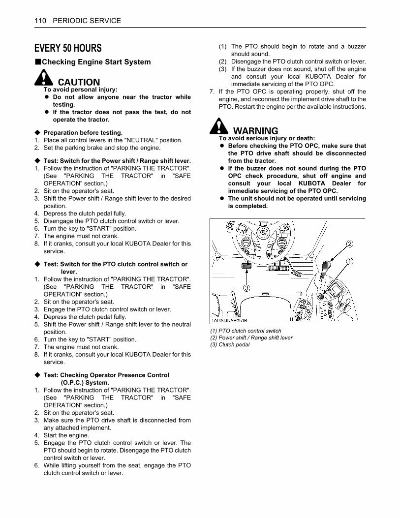
PERIODIC SERVICE110
EVERY 50 HOURSBChecking Engine Start System
To avoid personal injury:A Do not allow anyone near the tractor while
testing.A If the tractor does not pass the test, do not
operate the tractor.
C Preparation before testing.1. Place all control levers in the "NEUTRAL" position.2. Set the parking brake and stop the engine.
C Test: Switch for the Power shift / Range shift lever.1. Follow the instruction of "PARKING THE TRACTOR".
(See "PARKING THE TRACTOR" in "SAFEOPERATION" section.)
2. Sit on the operator's seat.3. Shift the Power shift / Range shift lever to the desired
position.4. Depress the clutch pedal fully.5. Disengage the PTO clutch control switch or lever.6. Turn the key to "START" position.7. The engine must not crank.8. If it cranks, consult your local KUBOTA Dealer for this
service.
C Test: Switch for the PTO clutch control switch or lever.
1. Follow the instruction of "PARKING THE TRACTOR".(See "PARKING THE TRACTOR" in "SAFEOPERATION" section.)
2. Sit on the operator's seat.3. Engage the PTO clutch control switch or lever.4. Depress the clutch pedal fully.5. Shift the Power shift / Range shift lever to the neutral
position.6. Turn the key to "START" position.7. The engine must not crank.8. If it cranks, consult your local KUBOTA Dealer for this
service.
C Test: Checking Operator Presence Control (O.P.C.) System.
1. Follow the instruction of "PARKING THE TRACTOR".(See "PARKING THE TRACTOR" in "SAFEOPERATION" section.)
2. Sit on the operator's seat.3. Make sure the PTO drive shaft is disconnected from
any attached implement.4. Start the engine.5. Engage the PTO clutch control switch or lever. The
PTO should begin to rotate. Disengage the PTO clutchcontrol switch or lever.
6. While lifting yourself from the seat, engage the PTOclutch control switch or lever.
(1) The PTO should begin to rotate and a buzzershould sound.
(2) Disengage the PTO clutch control switch or lever.(3) If the buzzer does not sound, shut off the engine
and consult your local KUBOTA Dealer forimmediate servicing of the PTO OPC.
7. If the PTO OPC is operating properly, shut off theengine, and reconnect the implement drive shaft to thePTO. Restart the engine per the available instructions.
To avoid serious injury or death:A Before checking the PTO OPC, make sure that
the PTO drive shaft should be disconnectedfrom the tractor.
A If the buzzer does not sound during the PTOOPC check procedure, shut off engine andconsult your local KUBOTA Dealer forimmediate servicing of the PTO OPC.
A The unit should not be operated until servicingis completed.
(1) PTO clutch control switch(2) Power shift / Range shift lever(3) Clutch pedal
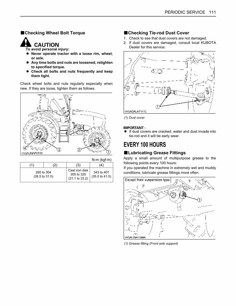
111PERIODIC SERVICE
BChecking Wheel Bolt Torque
To avoid personal injury:A Never operate tractor with a loose rim, wheel,
or axle.A Any time bolts and nuts are loosened, retighten
to specified torque.A Check all bolts and nuts frequently and keep
them tight.
Check wheel bolts and nuts regularly especially whennew. If they are loose, tighten them as follows.
BChecking Tie-rod Dust Cover1. Check to see that dust covers are not damaged.2. If dust covers are damaged, consult local KUBOTA
Dealer for this service.
A If dust covers are cracked, water and dust invade intotie-rod and it will be early wear.
EVERY 100 HOURSBLubricating Grease FittingsApply a small amount of multipurpose grease to thefollowing points every 100 hours:If you operated the machine in extremely wet and muddyconditions, lubricate grease fittings more often.
N-m (kgf-m)(1) (2) (3) (4)
260 to 304(26.5 to 31.0)
Cast iron disk305 to 325
(31.1 to 33.2)
343 to 401(35.0 to 41.0)
(1) Dust cover
(1) Grease fitting (Front axle support)
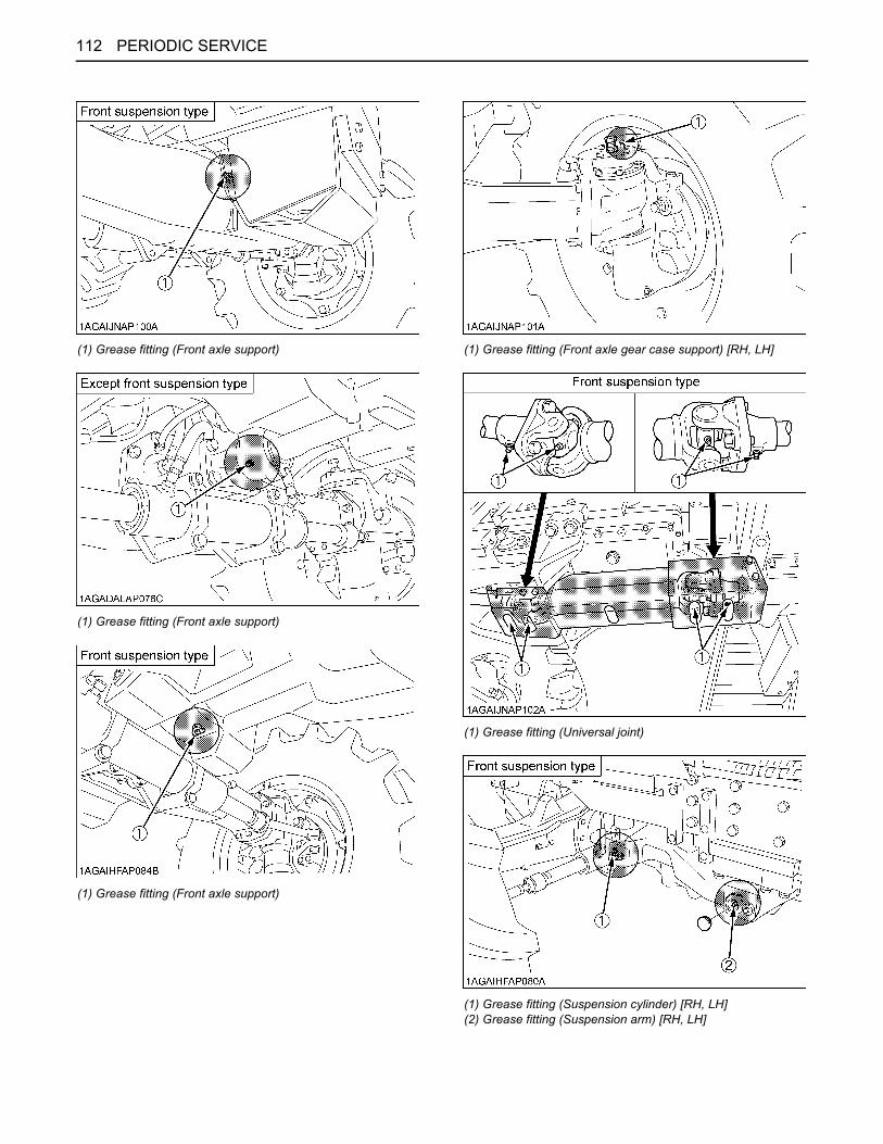
PERIODIC SERVICE112
(1) Grease fitting (Front axle support)
(1) Grease fitting (Front axle support)
(1) Grease fitting (Front axle support)
(1) Grease fitting (Front axle gear case support) [RH, LH]
(1) Grease fitting (Universal joint)
(1) Grease fitting (Suspension cylinder) [RH, LH](2) Grease fitting (Suspension arm) [RH, LH]
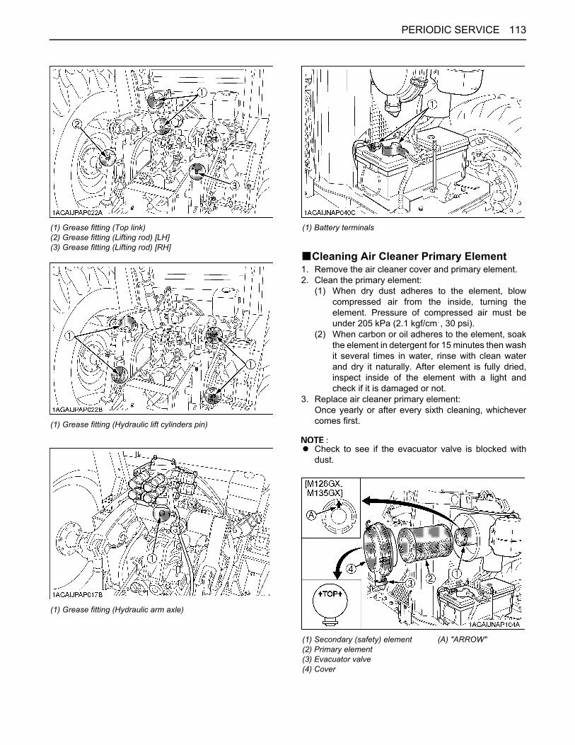
113PERIODIC SERVICE
BCleaning Air Cleaner Primary Element1. Remove the air cleaner cover and primary element.2. Clean the primary element:
(1) When dry dust adheres to the element, blowcompressed air from the inside, turning theelement. Pressure of compressed air must beunder 205 kPa (2.1 kgf/cm , 30 psi).
(2) When carbon or oil adheres to the element, soakthe element in detergent for 15 minutes then washit several times in water, rinse with clean waterand dry it naturally. After element is fully dried,inspect inside of the element with a light andcheck if it is damaged or not.
3. Replace air cleaner primary element:Once yearly or after every sixth cleaning, whichevercomes first.
A Check to see if the evacuator valve is blocked withdust.
(1) Grease fitting (Top link)(2) Grease fitting (Lifting rod) [LH](3) Grease fitting (Lifting rod) [RH]
(1) Grease fitting (Hydraulic lift cylinders pin)
(1) Grease fitting (Hydraulic arm axle)
(1) Battery terminals
(1) Secondary (safety) element(2) Primary element(3) Evacuator valve(4) Cover
(A) "ARROW"
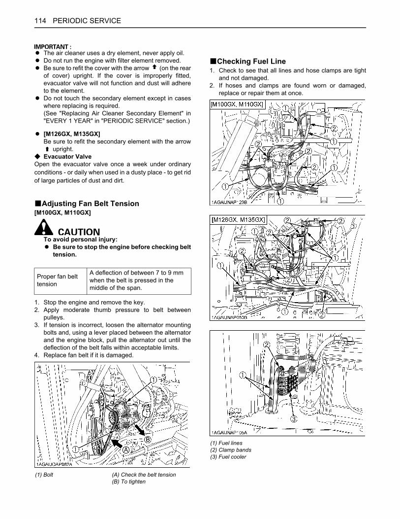
PERIODIC SERVICE114
A The air cleaner uses a dry element, never apply oil.A Do not run the engine with filter element removed.A Be sure to refit the cover with the arrow (on the rear
of cover) upright. If the cover is improperly fitted,evacuator valve will not function and dust will adhereto the element.
A Do not touch the secondary element except in caseswhere replacing is required.(See "Replacing Air Cleaner Secondary Element" in"EVERY 1 YEAR" in "PERIODIC SERVICE" section.)
A [M126GX, M135GX]Be sure to refit the secondary element with the arrow
upright.C Evacuator ValveOpen the evacuator valve once a week under ordinaryconditions - or daily when used in a dusty place - to get ridof large particles of dust and dirt.
BAdjusting Fan Belt Tension[M100GX, M110GX]
To avoid personal injury:A Be sure to stop the engine before checking belt
tension.
1. Stop the engine and remove the key.2. Apply moderate thumb pressure to belt between
pulleys.3. If tension is incorrect, loosen the alternator mounting
bolts and, using a lever placed between the alternatorand the engine block, pull the alternator out until thedeflection of the belt falls within acceptable limits.
4. Replace fan belt if it is damaged.
BChecking Fuel Line1. Check to see that all lines and hose clamps are tight
and not damaged.2. If hoses and clamps are found worn or damaged,
replace or repair them at once.
Proper fan belt tension
A deflection of between 7 to 9 mm when the belt is pressed in the middle of the span.
(1) Bolt (A) Check the belt tension(B) To tighten
(1) Fuel lines(2) Clamp bands(3) Fuel cooler
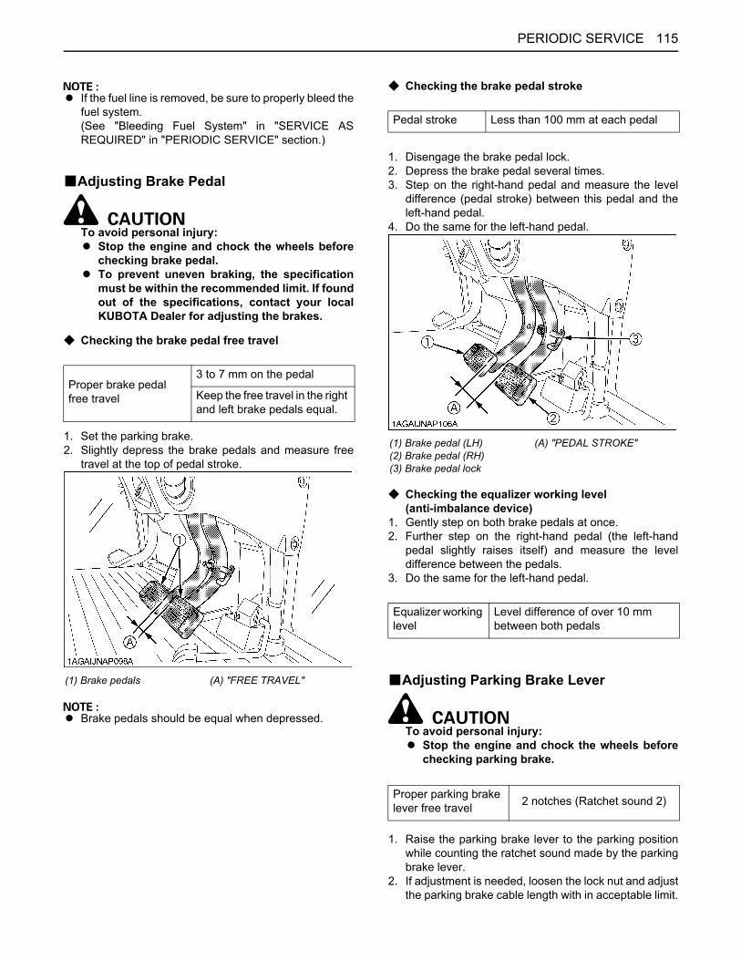
115PERIODIC SERVICE
A If the fuel line is removed, be sure to properly bleed thefuel system.(See "Bleeding Fuel System" in "SERVICE ASREQUIRED" in "PERIODIC SERVICE" section.)
BAdjusting Brake Pedal
To avoid personal injury:A Stop the engine and chock the wheels before
checking brake pedal.A To prevent uneven braking, the specification
must be within the recommended limit. If foundout of the specifications, contact your localKUBOTA Dealer for adjusting the brakes.
C Checking the brake pedal free travel
1. Set the parking brake.2. Slightly depress the brake pedals and measure free
travel at the top of pedal stroke.
A Brake pedals should be equal when depressed.
C Checking the brake pedal stroke
1. Disengage the brake pedal lock.2. Depress the brake pedal several times.3. Step on the right-hand pedal and measure the level
difference (pedal stroke) between this pedal and theleft-hand pedal.
4. Do the same for the left-hand pedal.
C Checking the equalizer working level(anti-imbalance device)
1. Gently step on both brake pedals at once.2. Further step on the right-hand pedal (the left-hand
pedal slightly raises itself) and measure the leveldifference between the pedals.
3. Do the same for the left-hand pedal.
BAdjusting Parking Brake Lever
To avoid personal injury:A Stop the engine and chock the wheels before
checking parking brake.
1. Raise the parking brake lever to the parking positionwhile counting the ratchet sound made by the parkingbrake lever.
2. If adjustment is needed, loosen the lock nut and adjustthe parking brake cable length with in acceptable limit.
Proper brake pedal free travel
3 to 7 mm on the pedal
Keep the free travel in the right and left brake pedals equal.
(1) Brake pedals (A) "FREE TRAVEL"
Pedal stroke Less than 100 mm at each pedal
(1) Brake pedal (LH)(2) Brake pedal (RH)(3) Brake pedal lock
(A) "PEDAL STROKE"
Equalizer working level
Level difference of over 10 mm between both pedals
Proper parking brake lever free travel 2 notches (Ratchet sound 2)
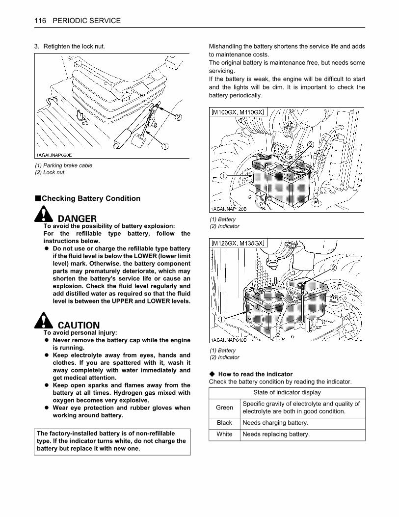
PERIODIC SERVICE116
3. Retighten the lock nut.
BChecking Battery Condition
To avoid the possibility of battery explosion:For the refillable type battery, follow theinstructions below.A Do not use or charge the refillable type battery
if the fluid level is below the LOWER (lower limitlevel) mark. Otherwise, the battery componentparts may prematurely deteriorate, which mayshorten the battery's service life or cause anexplosion. Check the fluid level regularly andadd distilled water as required so that the fluidlevel is between the UPPER and LOWER levels.
To avoid personal injury:A Never remove the battery cap while the engine
is running.A Keep electrolyte away from eyes, hands and
clothes. If you are spattered with it, wash itaway completely with water immediately andget medical attention.
A Keep open sparks and flames away from thebattery at all times. Hydrogen gas mixed withoxygen becomes very explosive.
A Wear eye protection and rubber gloves whenworking around battery.
Mishandling the battery shortens the service life and addsto maintenance costs.The original battery is maintenance free, but needs someservicing.If the battery is weak, the engine will be difficult to startand the lights will be dim. It is important to check thebattery periodically.
C How to read the indicatorCheck the battery condition by reading the indicator.
(1) Parking brake cable(2) Lock nut
The factory-installed battery is of non-refillable type. If the indicator turns white, do not charge the battery but replace it with new one.
(1) Battery(2) Indicator
(1) Battery(2) Indicator
State of indicator display
Green Specific gravity of electrolyte and quality of electrolyte are both in good condition.
Black Needs charging battery.
White Needs replacing battery.
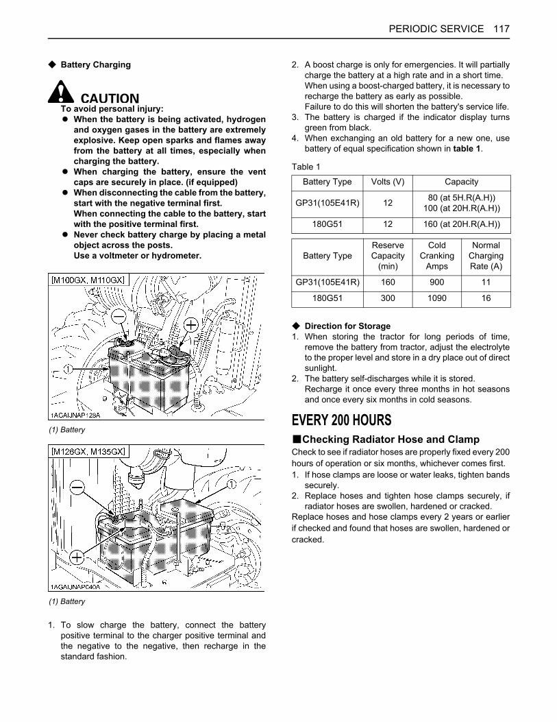
117PERIODIC SERVICE
C Battery Charging
To avoid personal injury: A When the battery is being activated, hydrogen
and oxygen gases in the battery are extremelyexplosive. Keep open sparks and flames awayfrom the battery at all times, especially whencharging the battery.
A When charging the battery, ensure the ventcaps are securely in place. (if equipped)
A When disconnecting the cable from the battery,start with the negative terminal first.When connecting the cable to the battery, startwith the positive terminal first.
A Never check battery charge by placing a metalobject across the posts.Use a voltmeter or hydrometer.
1. To slow charge the battery, connect the batterypositive terminal to the charger positive terminal andthe negative to the negative, then recharge in thestandard fashion.
2. A boost charge is only for emergencies. It will partiallycharge the battery at a high rate and in a short time.When using a boost-charged battery, it is necessary torecharge the battery as early as possible.Failure to do this will shorten the battery's service life.
3. The battery is charged if the indicator display turnsgreen from black.
4. When exchanging an old battery for a new one, usebattery of equal specification shown in table 1.
Table 1
C Direction for Storage1. When storing the tractor for long periods of time,
remove the battery from tractor, adjust the electrolyteto the proper level and store in a dry place out of directsunlight.
2. The battery self-discharges while it is stored.Recharge it once every three months in hot seasonsand once every six months in cold seasons.
EVERY 200 HOURSBChecking Radiator Hose and ClampCheck to see if radiator hoses are properly fixed every 200hours of operation or six months, whichever comes first.1. If hose clamps are loose or water leaks, tighten bands
securely.2. Replace hoses and tighten hose clamps securely, if
radiator hoses are swollen, hardened or cracked.Replace hoses and hose clamps every 2 years or earlierif checked and found that hoses are swollen, hardened orcracked.
(1) Battery
(1) Battery
Battery Type Volts (V) Capacity
GP31(105E41R) 12 80 (at 5H.R(A.H))100 (at 20H.R(A.H))
180G51 12 160 (at 20H.R(A.H))
Battery TypeReserve Capacity
(min)
Cold Cranking
Amps
NormalChargingRate (A)
GP31(105E41R) 160 900 11
180G51 300 1090 16
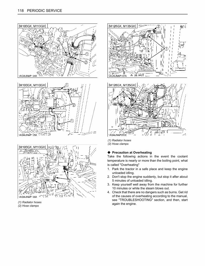
PERIODIC SERVICE118
C Precaution at OverheatingTake the following actions in the event the coolanttemperature is nearly or more than the boiling point, whatis called "Overheating"1. Park the tractor in a safe place and keep the engine
unloaded idling.2. Don't stop the engine suddenly, but stop it after about
5 minutes of unloaded idling.3. Keep yourself well away from the machine for further
10 minutes or while the steam blows out.4. Check that there are no dangers such as burns. Get rid
of the causes of overheating according to the manual,see "TROUBLESHOOTING" section, and then, startagain the engine.(1) Radiator hoses
(2) Hose clamps
(1) Radiator hoses(2) Hose clamps
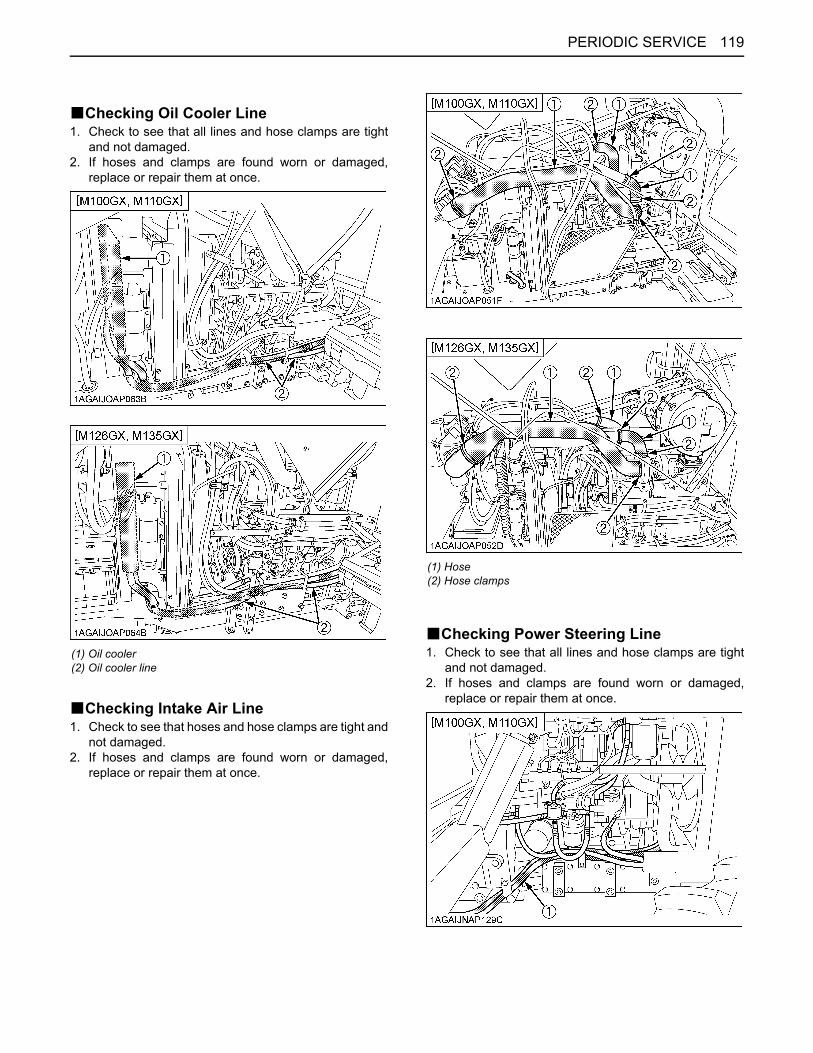
119PERIODIC SERVICE
BChecking Oil Cooler Line1. Check to see that all lines and hose clamps are tight
and not damaged.2. If hoses and clamps are found worn or damaged,
replace or repair them at once.
BChecking Intake Air Line1. Check to see that hoses and hose clamps are tight and
not damaged.2. If hoses and clamps are found worn or damaged,
replace or repair them at once.
BChecking Power Steering Line1. Check to see that all lines and hose clamps are tight
and not damaged.2. If hoses and clamps are found worn or damaged,
replace or repair them at once.
(1) Oil cooler(2) Oil cooler line
(1) Hose(2) Hose clamps
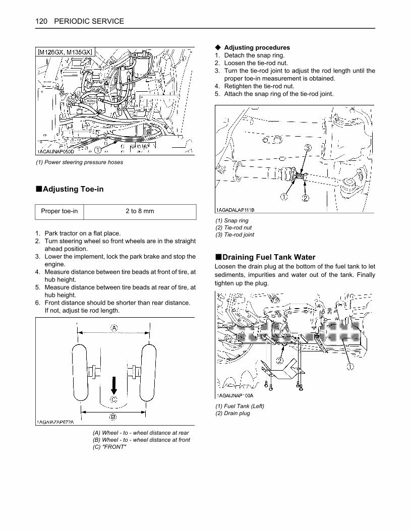
PERIODIC SERVICE120
BAdjusting Toe-in
1. Park tractor on a flat place.2. Turn steering wheel so front wheels are in the straight
ahead position.3. Lower the implement, lock the park brake and stop the
engine.4. Measure distance between tire beads at front of tire, at
hub height.5. Measure distance between tire beads at rear of tire, at
hub height.6. Front distance should be shorter than rear distance.
If not, adjust tie rod length.
C Adjusting procedures1. Detach the snap ring.2. Loosen the tie-rod nut.3. Turn the tie-rod joint to adjust the rod length until the
proper toe-in measurement is obtained.4. Retighten the tie-rod nut.5. Attach the snap ring of the tie-rod joint.
BDraining Fuel Tank WaterLoosen the drain plug at the bottom of the fuel tank to letsediments, impurities and water out of the tank. Finallytighten up the plug.
(1) Power steering pressure hoses
Proper toe-in 2 to 8 mm
(A) Wheel - to - wheel distance at rear(B) Wheel - to - wheel distance at front(C) "FRONT"
(1) Snap ring(2) Tie-rod nut(3) Tie-rod joint
(1) Fuel Tank (Left)(2) Drain plug
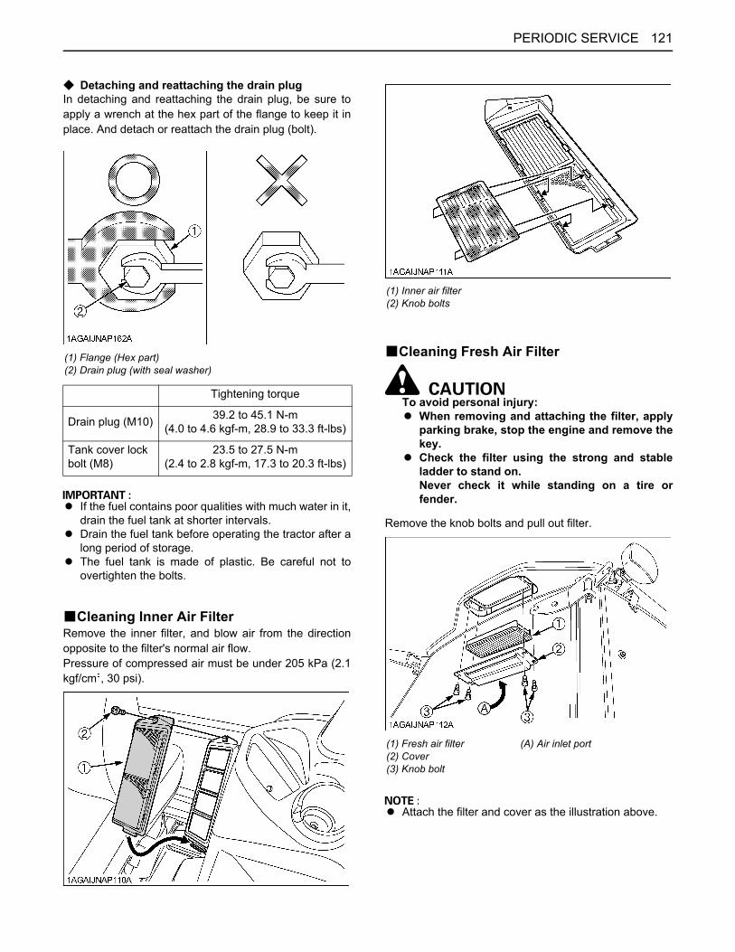
121PERIODIC SERVICE
C Detaching and reattaching the drain plugIn detaching and reattaching the drain plug, be sure toapply a wrench at the hex part of the flange to keep it inplace. And detach or reattach the drain plug (bolt).
A If the fuel contains poor qualities with much water in it,drain the fuel tank at shorter intervals.
A Drain the fuel tank before operating the tractor after along period of storage.
A The fuel tank is made of plastic. Be careful not toovertighten the bolts.
BCleaning Inner Air FilterRemove the inner filter, and blow air from the directionopposite to the filter's normal air flow.Pressure of compressed air must be under 205 kPa (2.1kgf/cm , 30 psi).
BCleaning Fresh Air Filter
To avoid personal injury:A When removing and attaching the filter, apply
parking brake, stop the engine and remove thekey.
A Check the filter using the strong and stableladder to stand on. Never check it while standing on a tire orfender.
Remove the knob bolts and pull out filter.
A Attach the filter and cover as the illustration above.
(1) Flange (Hex part)(2) Drain plug (with seal washer)
Tightening torque
Drain plug (M10) 39.2 to 45.1 N-m (4.0 to 4.6 kgf-m, 28.9 to 33.3 ft-lbs)
Tank cover lock bolt (M8)
23.5 to 27.5 N-m (2.4 to 2.8 kgf-m, 17.3 to 20.3 ft-lbs)
(1) Inner air filter(2) Knob bolts
(1) Fresh air filter(2) Cover(3) Knob bolt
(A) Air inlet port
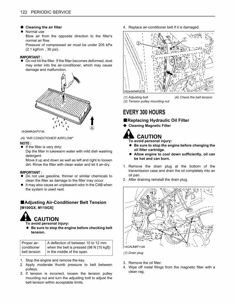
PERIODIC SERVICE122
C Cleaning the air filterA Normal use
Blow air from the opposite direction to the filter'snormal air flow.Pressure of compressed air must be under 205 kPa(2.1 kgf/cm , 30 psi).
A Do not hit the filter. If the filter becomes deformed, dustmay enter into the air-conditioner, which may causedamage and malfunction.
A If the filter is very dirty:Dip the filter in lukewarm water with mild dish washingdetergent.Move it up and down as well as left and right to loosendirt. Rinse the filter with clean water and let it air-dry.
A Do not use gasoline, thinner or similar chemicals toclean the filter as damage to the filter may occur.
A It may also cause an unpleasant odor in the CAB whenthe system is used next.
BAdjusting Air-Conditioner Belt Tension[M100GX, M110GX]
To avoid personal injury:A Be sure to stop the engine before checking belt
tension.
1. Stop the engine and remove the key.2. Apply moderate thumb pressure to belt between
pulleys.3. If tension is incorrect, loosen the tension pulley
mounting nut and turn the adjusting bolt to adjust thebelt tension within acceptable limits.
4. Replace air-conditioner belt if it is damaged.
EVERY 300 HOURSBReplacing Hydraulic Oil FilterC Cleaning Magnetic Filter
To avoid personal injury:A Be sure to stop the engine before changing the
oil filter cartridge.A Allow engine to cool down sufficiently, oil can
be hot and can burn.
1. Remove the drain plug at the bottom of thetransmission case and drain the oil completely into anoil pan.
2. After draining reinstall the drain plug.
3. Remove the oil filter.4. Wipe off metal filings from the magnetic filter with a
clean rag.
(A) "AIR CONDITIONER AIRFLOW"
Proper air-conditioner belt tension
A deflection of between 10 to 12 mm when the belt is pressed (98 N [10 kgf]) in the middle of the span.
(1) Adjusting bolt(2) Tension pulley mounting nut
(A) Check the belt tension
(1) Drain plug
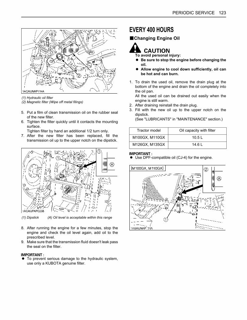
123PERIODIC SERVICE
5. Put a film of clean transmission oil on the rubber sealof the new filter.
6. Tighten the filter quickly until it contacts the mountingsurface.Tighten filter by hand an additional 1/2 turn only.
7. After the new filter has been replaced, fill thetransmission oil up to the upper notch on the dipstick.
8. After running the engine for a few minutes, stop theengine and check the oil level again, add oil to theprescribed level.
9. Make sure that the transmission fluid doesn't leak passthe seal on the filter.
A To prevent serious damage to the hydraulic system,use only a KUBOTA genuine filter.
EVERY 400 HOURSBChanging Engine Oil
To avoid personal injury:A Be sure to stop the engine before changing the
oil. A Allow engine to cool down sufficiently, oil can
be hot and can burn.
1. To drain the used oil, remove the drain plug at thebottom of the engine and drain the oil completely intothe oil pan.All the used oil can be drained out easily when theengine is still warm.
2. After draining reinstall the drain plug.3. Fill with the new oil up to the upper notch on the
dipstick.(See "LUBRICANTS" in "MAINTENANCE" section.)
A Use DPF-compatible oil (CJ-4) for the engine.
(1) Hydraulic oil filter(2) Magnetic filter (Wipe off metal filings)
(1) Dipstick (A) Oil level is acceptable within this range
Tractor model Oil capacity with filter
M100GX, M110GX 10.5 L
M126GX, M135GX 14.6 L
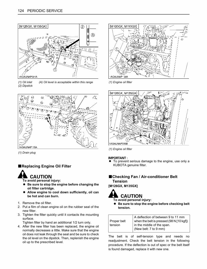
PERIODIC SERVICE124
BReplacing Engine Oil Filter
To avoid personal injury:A Be sure to stop the engine before changing the
oil filter cartridge.A Allow engine to cool down sufficiently, oil can
be hot and can burn.
1. Remove the oil filter.2. Put a film of clean engine oil on the rubber seal of the
new filter.3. Tighten the filter quickly until it contacts the mounting
surface.Tighten filter by hand an additional 1/2 turn only.
4. After the new filter has been replaced, the engine oilnormally decreases a little. Make sure that the engineoil does not leak through the seal and be sure to checkthe oil level on the dipstick. Then, replenish the engineoil up to the prescribed level.
A To prevent serious damage to the engine, use only aKUBOTA genuine filter.
BChecking Fan / Air-conditioner Belt Tension
[M126GX, M135GX]
To avoid personal injury:A Be sure to stop the engine before checking belt
tension.
The belt is of self-tension type and needs noreadjustment. Check the belt tension in the followingprocedure. If the deflection is out of spec or the belt itselfis found damaged, replace it with new one.
(1) Oil inlet(2) Dipstick
(A) Oil level is acceptable within this range
(1) Drain plug
(1) Engine oil filter
(1) Engine oil filter
Proper belt tension
A deflection of between 9 to 11 mm when the belt is pressed (98 N [10 kgf]) in the middle of the span.(New belt: 7 to 9 mm)
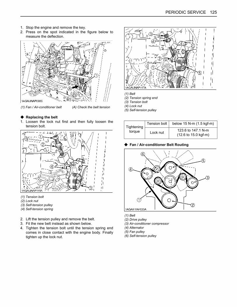
125PERIODIC SERVICE
1. Stop the engine and remove the key.2. Press on the spot indicated in the figure below to
measure the deflection.
C Replacing the belt1. Loosen the lock nut first and then fully loosen the
tension bolt.
2. Lift the tension pulley and remove the belt.3. Fit the new belt instead as shown below.4. Tighten the tension bolt until the tension spring end
comes in close contact with the engine body. Finallytighten up the lock nut.
C Fan / Air-conditioner Belt Routing
(1) Fan / Air-conditioner belt (A) Check the belt tension
(1) Tension bolt(2) Lock nut(3) Self-tension pulley(4) Self-tension spring
(1) Belt(2) Tension spring end(3) Tension bolt(4) Lock nut(5) Self-tension pulley
Tightening torque
Tension bolt below 15 N-m (1.5 kgf-m)
Lock nut 123.6 to 147.1 N-m (12.6 to 15.0 kgf-m)
(1) Belt(2) Drive pulley(3) Air-conditioner compressor(4) Alternator(5) Fan pulley(6) Self-tension pulley
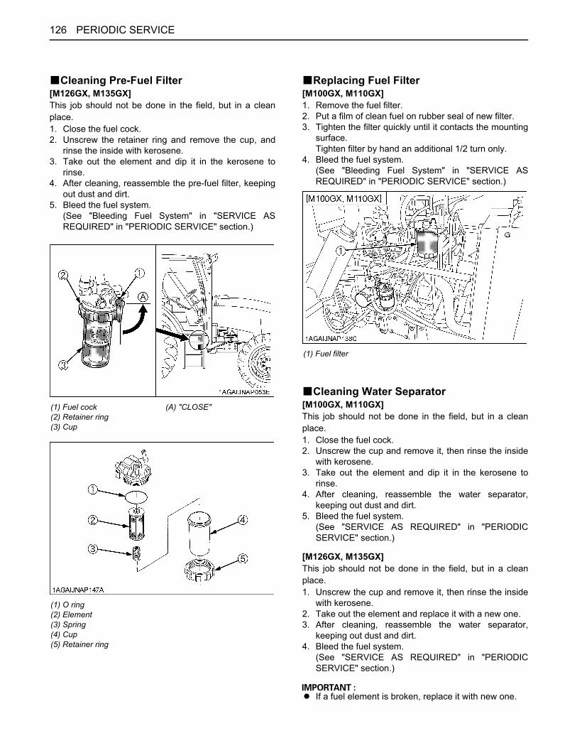
PERIODIC SERVICE126
BCleaning Pre-Fuel Filter[M126GX, M135GX]This job should not be done in the field, but in a cleanplace.1. Close the fuel cock.2. Unscrew the retainer ring and remove the cup, and
rinse the inside with kerosene.3. Take out the element and dip it in the kerosene to
rinse.4. After cleaning, reassemble the pre-fuel filter, keeping
out dust and dirt.5. Bleed the fuel system.
(See "Bleeding Fuel System" in "SERVICE ASREQUIRED" in "PERIODIC SERVICE" section.)
BReplacing Fuel Filter[M100GX, M110GX]1. Remove the fuel filter.2. Put a film of clean fuel on rubber seal of new filter.3. Tighten the filter quickly until it contacts the mounting
surface.Tighten filter by hand an additional 1/2 turn only.
4. Bleed the fuel system.(See "Bleeding Fuel System" in "SERVICE ASREQUIRED" in "PERIODIC SERVICE" section.)
BCleaning Water Separator[M100GX, M110GX]This job should not be done in the field, but in a cleanplace.1. Close the fuel cock.2. Unscrew the cup and remove it, then rinse the inside
with kerosene.3. Take out the element and dip it in the kerosene to
rinse.4. After cleaning, reassemble the water separator,
keeping out dust and dirt.5. Bleed the fuel system.
(See "SERVICE AS REQUIRED" in "PERIODICSERVICE" section.)
[M126GX, M135GX]This job should not be done in the field, but in a cleanplace.1. Unscrew the cup and remove it, then rinse the inside
with kerosene.2. Take out the element and replace it with a new one.3. After cleaning, reassemble the water separator,
keeping out dust and dirt.4. Bleed the fuel system.
(See "SERVICE AS REQUIRED" in "PERIODICSERVICE" section.)
A If a fuel element is broken, replace it with new one.
(1) Fuel cock(2) Retainer ring(3) Cup
(A) "CLOSE"
(1) O ring(2) Element(3) Spring(4) Cup(5) Retainer ring
(1) Fuel filter

127PERIODIC SERVICE
A If the water separator and/or fuel filter is not wellmaintained, the supply pump and injector may bedamaged earlier than expected.
BCleaning Fuel Solenoid Pump Element[M126GX, M135GX]1. Close the fuel cock.2. Unscrew the cover's nut and remove the cover from
the fuel solenoid pump.3. Remove the cover, magnet, and element and clean
with kerosene.4. Refer to the diagram below and reassemble the parts
as they were before.5. Open the fuel cock.
A When assembling the parts, be careful that no dirt ordust contacts them.
A Be sure to install the cover securely.A After assembly, be sure to bleed the air from the fuel
system. (See "Bleeding Fuel System" in "SERVICEAS REQUIRED" in "PERIODIC SERVICE".)
(1) O ring(2) Element(3) Element cup(4) Red float(5) Cup(6) Drain plug
(1) O ring(2) Element(3) Red float(4) Cup(5) Drain plug
(1) Fuel solenoid pump
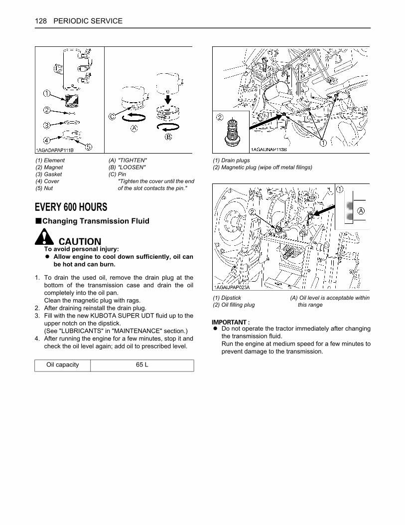
PERIODIC SERVICE128
EVERY 600 HOURSBChanging Transmission Fluid
To avoid personal injury:A Allow engine to cool down sufficiently, oil can
be hot and can burn.
1. To drain the used oil, remove the drain plug at thebottom of the transmission case and drain the oilcompletely into the oil pan.Clean the magnetic plug with rags.
2. After draining reinstall the drain plug.3. Fill with the new KUBOTA SUPER UDT fluid up to the
upper notch on the dipstick.(See "LUBRICANTS" in "MAINTENANCE" section.)
4. After running the engine for a few minutes, stop it andcheck the oil level again; add oil to prescribed level.
A Do not operate the tractor immediately after changingthe transmission fluid.Run the engine at medium speed for a few minutes toprevent damage to the transmission.
(1) Element(2) Magnet(3) Gasket(4) Cover(5) Nut
(A)(B)(C)
"TIGHTEN""LOOSEN"Pin "Tighten the cover until the endof the slot contacts the pin."
Oil capacity 65 L
(1) Drain plugs(2) Magnetic plug (wipe off metal filings)
(1) Dipstick(2) Oil filling plug
(A) Oil level is acceptable within this range
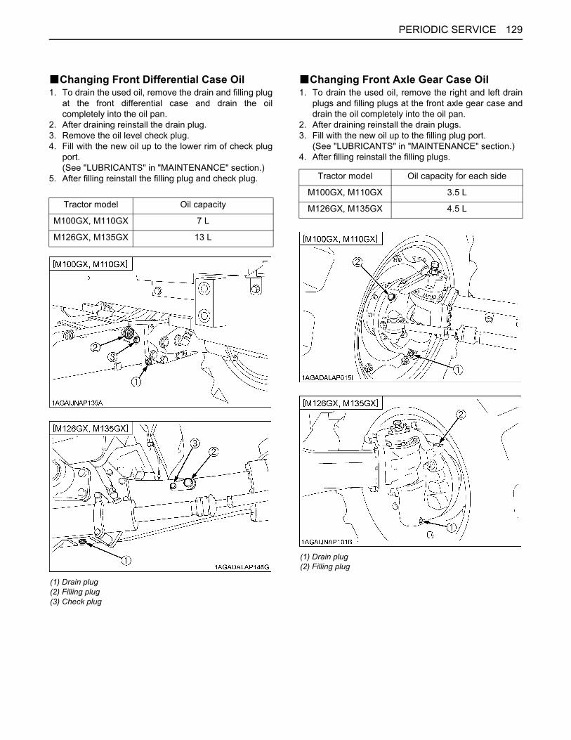
129PERIODIC SERVICE
BChanging Front Differential Case Oil1. To drain the used oil, remove the drain and filling plug
at the front differential case and drain the oilcompletely into the oil pan.
2. After draining reinstall the drain plug.3. Remove the oil level check plug.4. Fill with the new oil up to the lower rim of check plug
port.(See "LUBRICANTS" in "MAINTENANCE" section.)
5. After filling reinstall the filling plug and check plug.
BChanging Front Axle Gear Case Oil1. To drain the used oil, remove the right and left drain
plugs and filling plugs at the front axle gear case anddrain the oil completely into the oil pan.
2. After draining reinstall the drain plugs.3. Fill with the new oil up to the filling plug port.
(See "LUBRICANTS" in "MAINTENANCE" section.)4. After filling reinstall the filling plugs.
Tractor model Oil capacity
M100GX, M110GX 7 L
M126GX, M135GX 13 L
(1) Drain plug(2) Filling plug(3) Check plug
Tractor model Oil capacity for each side
M100GX, M110GX 3.5 L
M126GX, M135GX 4.5 L
(1) Drain plug(2) Filling plug

PERIODIC SERVICE130
BAdjusting Front Axle PivotIf the front axle pivot pin adjustment is not correct, frontwheel vibration can occur causing vibration in the steeringwheel.
C Adjusting procedureLoosen the lock nut, screw-in the adjusting screw untilseated, then tighten the screw with an additional 1/6 turn.Re-tighten the lock nut.
BAdjusting King-pin PivotLoosen the lock nut and tighten the adjusting screw withfollowing torque:
EVERY 800 HOURSBReplacing Fuel Filter[M126GX, M135GX]1. Remove the fuel filter.2. Put a film of clean fuel on rubber seal of new filter.3. Tighten the filter quickly until it contacts the mounting
surface.Tighten filter by hand an additional 1/2 turn only.
4. Bleed the fuel system.(See "Bleeding Fuel System" in "SERVICE ASREQUIRED" in "PERIODIC SERVICE" section.)
BAdjusting Engine Valve ClearanceConsult your local KUBOTA Dealer for this service.
EVERY 1500 HOURSBCleaning Fuel Injector Nozzle TipConsult your local KUBOTA Dealer for this service.
BChecking and Cleaning EGR CoolerConsult your local KUBOTA Dealer for this service.
BChecking Accumulator[Front suspension type]Consult your local KUBOTA Dealer for this service.
EVERY 3000 HOURSBChecking TurbochargerConsult your local KUBOTA Dealer for this service.
BChecking Supply PumpConsult your local KUBOTA Dealer for this service.
(1) Adjusting screw(2) Lock nut
Adjusting screw 4.9 to 9.8 N-m, 0.5 to 1.0 kgf-m
Lock nut 98.1 to 147 N-m, 10 to 15 kgf-m
(1) Adjusting screw(2) Lock nut
(1) Fuel filter
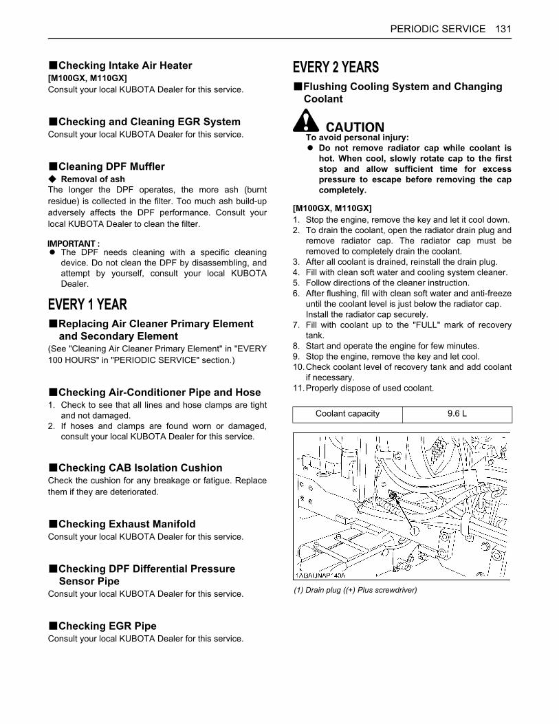
131PERIODIC SERVICE
BChecking Intake Air Heater[M100GX, M110GX]Consult your local KUBOTA Dealer for this service.
BChecking and Cleaning EGR SystemConsult your local KUBOTA Dealer for this service.
BCleaning DPF MufflerC Removal of ashThe longer the DPF operates, the more ash (burntresidue) is collected in the filter. Too much ash build-upadversely affects the DPF performance. Consult yourlocal KUBOTA Dealer to clean the filter.
A The DPF needs cleaning with a specific cleaningdevice. Do not clean the DPF by disassembling, andattempt by yourself, consult your local KUBOTADealer.
EVERY 1 YEARBReplacing Air Cleaner Primary Element
and Secondary Element(See "Cleaning Air Cleaner Primary Element" in "EVERY100 HOURS" in "PERIODIC SERVICE" section.)
BChecking Air-Conditioner Pipe and Hose1. Check to see that all lines and hose clamps are tight
and not damaged.2. If hoses and clamps are found worn or damaged,
consult your local KUBOTA Dealer for this service.
BChecking CAB Isolation CushionCheck the cushion for any breakage or fatigue. Replacethem if they are deteriorated.
BChecking Exhaust ManifoldConsult your local KUBOTA Dealer for this service.
BChecking DPF Differential Pressure Sensor Pipe
Consult your local KUBOTA Dealer for this service.
BChecking EGR PipeConsult your local KUBOTA Dealer for this service.
EVERY 2 YEARSBFlushing Cooling System and Changing
Coolant
To avoid personal injury:A Do not remove radiator cap while coolant is
hot. When cool, slowly rotate cap to the firststop and allow sufficient time for excesspressure to escape before removing the capcompletely.
[M100GX, M110GX]1. Stop the engine, remove the key and let it cool down.2. To drain the coolant, open the radiator drain plug and
remove radiator cap. The radiator cap must beremoved to completely drain the coolant.
3. After all coolant is drained, reinstall the drain plug.4. Fill with clean soft water and cooling system cleaner.5. Follow directions of the cleaner instruction.6. After flushing, fill with clean soft water and anti-freeze
until the coolant level is just below the radiator cap.Install the radiator cap securely.
7. Fill with coolant up to the "FULL" mark of recoverytank.
8. Start and operate the engine for few minutes.9. Stop the engine, remove the key and let cool. 10.Check coolant level of recovery tank and add coolant
if necessary.11.Properly dispose of used coolant.
Coolant capacity 9.6 L
(1) Drain plug ((+) Plus screwdriver)
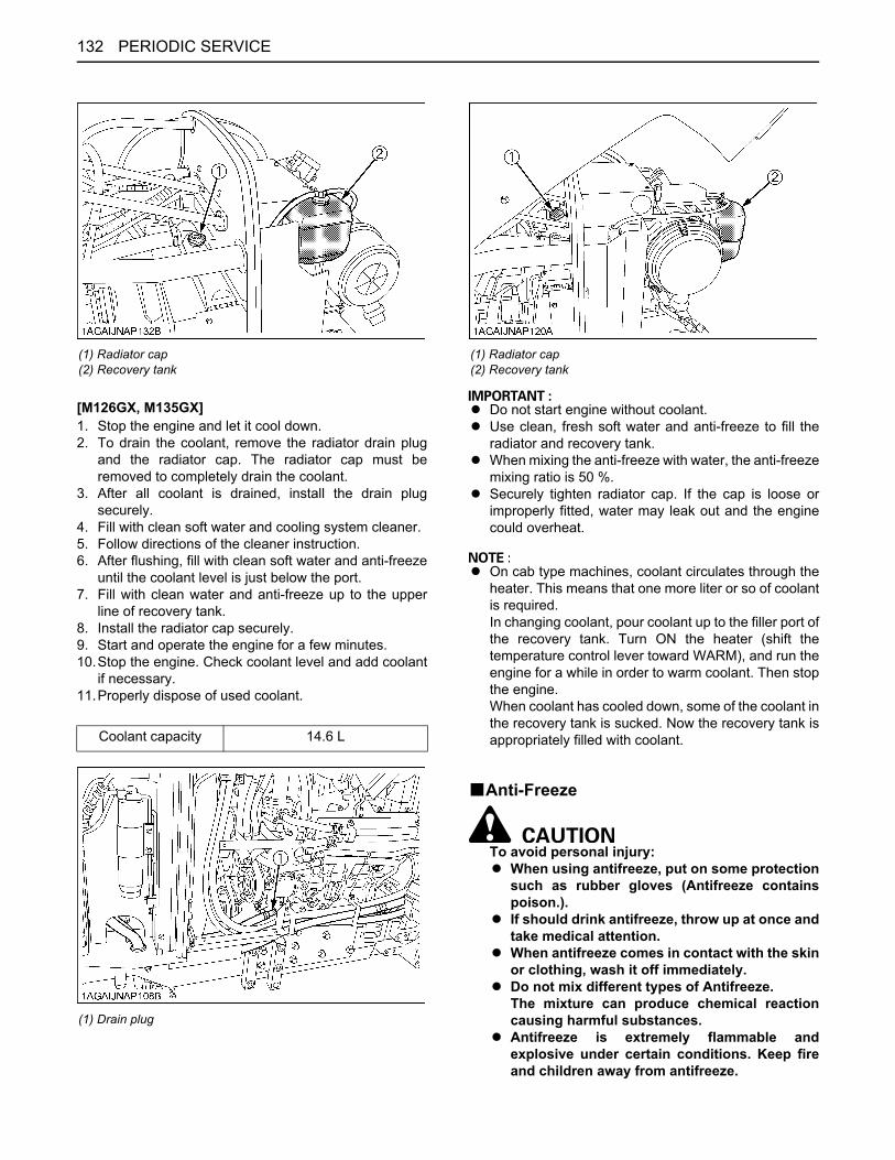
PERIODIC SERVICE132
[M126GX, M135GX]1. Stop the engine and let it cool down.2. To drain the coolant, remove the radiator drain plug
and the radiator cap. The radiator cap must beremoved to completely drain the coolant.
3. After all coolant is drained, install the drain plugsecurely.
4. Fill with clean soft water and cooling system cleaner.5. Follow directions of the cleaner instruction.6. After flushing, fill with clean soft water and anti-freeze
until the coolant level is just below the port.7. Fill with clean water and anti-freeze up to the upper
line of recovery tank.8. Install the radiator cap securely.9. Start and operate the engine for a few minutes.10.Stop the engine. Check coolant level and add coolant
if necessary.11.Properly dispose of used coolant.
A Do not start engine without coolant.A Use clean, fresh soft water and anti-freeze to fill the
radiator and recovery tank.A When mixing the anti-freeze with water, the anti-freeze
mixing ratio is 50 %.A Securely tighten radiator cap. If the cap is loose or
improperly fitted, water may leak out and the enginecould overheat.
A On cab type machines, coolant circulates through theheater. This means that one more liter or so of coolantis required.In changing coolant, pour coolant up to the filler port ofthe recovery tank. Turn ON the heater (shift thetemperature control lever toward WARM), and run theengine for a while in order to warm coolant. Then stopthe engine.When coolant has cooled down, some of the coolant inthe recovery tank is sucked. Now the recovery tank isappropriately filled with coolant.
BAnti-Freeze
To avoid personal injury:A When using antifreeze, put on some protection
such as rubber gloves (Antifreeze containspoison.).
A If should drink antifreeze, throw up at once andtake medical attention.
A When antifreeze comes in contact with the skinor clothing, wash it off immediately.
A Do not mix different types of Antifreeze.The mixture can produce chemical reactioncausing harmful substances.
A Antifreeze is extremely flammable andexplosive under certain conditions. Keep fireand children away from antifreeze.
(1) Radiator cap(2) Recovery tank
Coolant capacity 14.6 L
(1) Drain plug
(1) Radiator cap(2) Recovery tank

133PERIODIC SERVICE
A When draining fluids from the engine, placesome container underneath the engine body.
A Do not pour waste onto the grounds, down adrain, or into any water source.
A Also, observe the relevant environmentalprotection regulations when disposing ofantifreeze.
If it freezes, coolant can damage the cylinders andradiator. If the ambient temperature falls below 0 orbefore a long-term storage, let out cooling watercompletely, or mix fresh water with long-life coolant and fillthe radiator and recovery tank with the mixture.1. Long-life coolant (hereafter LLC) comes in several
types. Use ethylene glycol (EG) type for this engine.2. Before employing LLC-mixed cooling water, fill the
radiator with fresh water and empty it again.Repeat this procedure 2 or 3 times to clean up theinside.
3. Mixing the LLCPut the LLC in cooling water in the percentage (%) fora target temperature. When mixing, stir it up well, andthen fill into the radiator.
4. The procedure for the mixing of water and antifreezediffers according to the make of the antifreeze and theambient temperature. Refer to SAE J1034 standard,more specifically also to SAE J814c.
A When the antifreeze is mixed with water, theantifreeze mixing ratio must be less than 50%.
D At 1.013 x 10 Pa (760mmHg) pressure (atmospheric).A higher boiling point is obtained by using a radiatorpressure cap which permits the development ofpressure within the cooling system.
5. Adding the LLC(1) Add only water if the mixture reduces in amount
by evaporation.(2) If there is a mixture leak, add the LLC of the same
manufacturer and type in the same mixturepercentage.D Never add any long-life coolant of different
manufacturer. (Different brands may havedifferent additive components, and the enginemay fail to perform as specified.)
6. When the LLC is mixed, do not employ any radiatorcleaning agent. The LLC contains anticorrosive agent.If mixed with the cleaning agent, sludge may build up,adversely affecting the engine parts.
7. Kubota's genuine long-life coolant has a service life of2 years. Be sure to change the coolant every 2 years.
A The above data represent industry standards thatnecessitate a minimum glycol content in theconcentrated antifreeze.
A When the coolant level drops due to evaporation, addwater only to keep the antifreeze mixing ratio less than50%. In case of leakage, add antifreeze and water inthe specified mixing ratio before filling in to theradiator.
BReplacing Radiator Hose (Water pipes)Replace the hoses and clamps.(See "Checking Radiator Hose and Clamp" in "EVERY200 HOURS" in "PERIODIC SERVICE" section.)
BReplacing Power Steering HoseConsult your local KUBOTA Dealer for this service.
BReplacing Fuel HoseConsult your local KUBOTA Dealer for this service.
BReplacing Oil Cooler LineConsult your local KUBOTA Dealer for this service.
BReplacing Intake Air LineConsult your local KUBOTA Dealer for this service.
BReplacing DPF Differential Pressure Sensor Hose
Consult your local KUBOTA Dealer for this service.
BReplacing Boost Sensor HoseConsult your local KUBOTA Dealer for this service.
BReplacing Parking Brake CableConsult your local KUBOTA Dealer for this service.
BReplacing Brake HoseConsult your local KUBOTA Dealer for this service.
BReplacing Clutch HoseConsult your local KUBOTA Dealer for this service.
BReplacing Differential Lock HoseConsult your local KUBOTA Dealer for this service.
Vol %Anti-freeze
Freezing Point Boiling Point*
4050
-24-37
106108
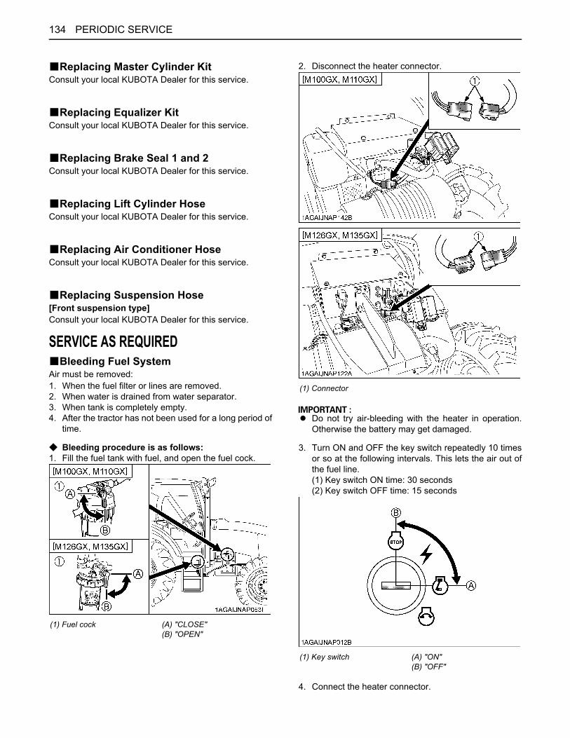
PERIODIC SERVICE134
BReplacing Master Cylinder KitConsult your local KUBOTA Dealer for this service.
BReplacing Equalizer KitConsult your local KUBOTA Dealer for this service.
BReplacing Brake Seal 1 and 2Consult your local KUBOTA Dealer for this service.
BReplacing Lift Cylinder HoseConsult your local KUBOTA Dealer for this service.
BReplacing Air Conditioner HoseConsult your local KUBOTA Dealer for this service.
BReplacing Suspension Hose[Front suspension type]Consult your local KUBOTA Dealer for this service.
SERVICE AS REQUIREDBBleeding Fuel SystemAir must be removed:1. When the fuel filter or lines are removed.2. When water is drained from water separator.3. When tank is completely empty.4. After the tractor has not been used for a long period of
time.
C Bleeding procedure is as follows:1. Fill the fuel tank with fuel, and open the fuel cock.
2. Disconnect the heater connector.
A Do not try air-bleeding with the heater in operation.Otherwise the battery may get damaged.
3. Turn ON and OFF the key switch repeatedly 10 timesor so at the following intervals. This lets the air out ofthe fuel line.(1) Key switch ON time: 30 seconds(2) Key switch OFF time: 15 seconds
4. Connect the heater connector.
(1) Fuel cock (A) "CLOSE"(B) "OPEN"
(1) Connector
(1) Key switch (A) "ON"(B) "OFF"
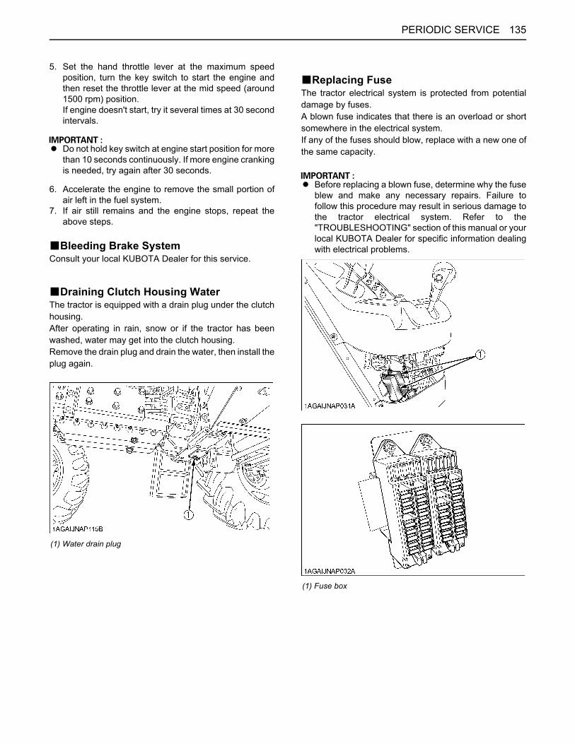
135PERIODIC SERVICE
5. Set the hand throttle lever at the maximum speedposition, turn the key switch to start the engine andthen reset the throttle lever at the mid speed (around1500 rpm) position.If engine doesn't start, try it several times at 30 secondintervals.
A Do not hold key switch at engine start position for morethan 10 seconds continuously. If more engine crankingis needed, try again after 30 seconds.
6. Accelerate the engine to remove the small portion ofair left in the fuel system.
7. If air still remains and the engine stops, repeat theabove steps.
BBleeding Brake SystemConsult your local KUBOTA Dealer for this service.
BDraining Clutch Housing WaterThe tractor is equipped with a drain plug under the clutchhousing.After operating in rain, snow or if the tractor has beenwashed, water may get into the clutch housing.Remove the drain plug and drain the water, then install theplug again.
BReplacing FuseThe tractor electrical system is protected from potentialdamage by fuses.A blown fuse indicates that there is an overload or shortsomewhere in the electrical system.If any of the fuses should blow, replace with a new one ofthe same capacity.
A Before replacing a blown fuse, determine why the fuseblew and make any necessary repairs. Failure tofollow this procedure may result in serious damage tothe tractor electrical system. Refer to the"TROUBLESHOOTING" section of this manual or yourlocal KUBOTA Dealer for specific information dealingwith electrical problems.
(1) Water drain plug
(1) Fuse box
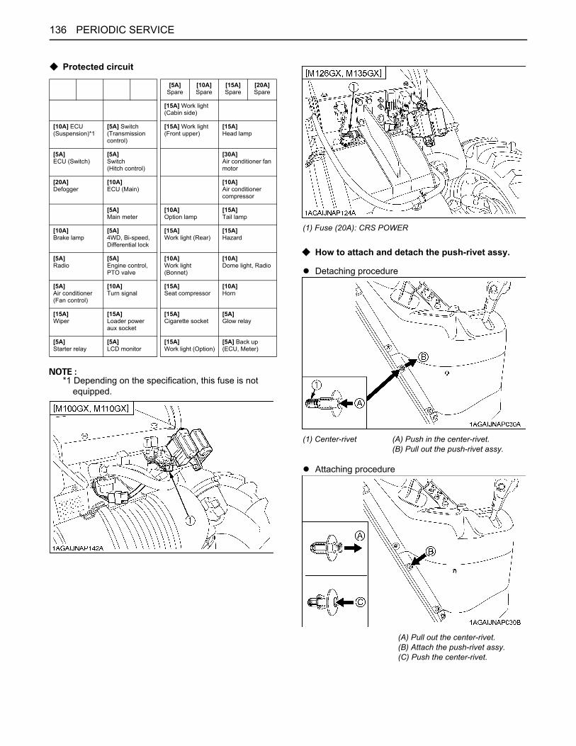
PERIODIC SERVICE136
C Protected circuit
*1 Depending on the specification, this fuse is not equipped.
C How to attach and detach the push-rivet assy.
A Detaching procedure
A Attaching procedure
[5A]Spare
[10A]Spare
[15A]Spare
[20A]Spare
[15A] Work light (Cabin side)
[10A] ECU (Suspension)*1
[5A] Switch (Transmission control)
[15A] Work light(Front upper)
[15A]Head lamp
[5A]ECU (Switch)
[5A]Switch(Hitch control)
[30A]Air conditioner fan motor
[20A]Defogger
[10A]ECU (Main)
[10A]Air conditioner compressor
[5A]Main meter
[10A]Option lamp
[15A]Tail lamp
[10A]Brake lamp
[5A]4WD, Bi-speed, Differential lock
[15A]Work light (Rear)
[15A]Hazard
[5A]Radio
[5A]Engine control, PTO valve
[10A]Work light (Bonnet)
[10A]Dome light, Radio
[5A]Air conditioner (Fan control)
[10A]Turn signal
[15A]Seat compressor
[10A]Horn
[15A]Wiper
[15A]Loader power aux socket
[15A]Cigarette socket
[5A]Glow relay
[5A]Starter relay
[5A]LCD monitor
[15A]Work light (Option)
[5A] Back up(ECU, Meter)
(1) Fuse (20A): CRS POWER
(1) Center-rivet (A) Push in the center-rivet.(B) Pull out the push-rivet assy.
(A) Pull out the center-rivet.(B) Attach the push-rivet assy.(C) Push the center-rivet.

137PERIODIC SERVICE
BReplacing Slow-Blow FusesThe slow-blow fuses are intended to protect the electricalcabling. If any of them has blown out, be sure to pinpointthe cause. Never use any substitute, use only a KUBOTAgenuine part.
C Replacement procedure[Non bolt fixed slow-blow fuse:]1. Disconnect the negative cord of the battery.2. Pull out the fuse from the fuse box.3. Replace with a new one of the same capacity.[Bolt fixed slow-blow fuse:]Consult your local KUBOTA Dealer for this service.
No. Capacity Protected circuit Type1 40A Defogger Non bolt
fixed2 30A Electrical outlet3 40A Work light (Rear)
Bolt fixed
4
120A [M100GX, M110GX]
Engine preheat
40A [M126GX, M135GX]
Work light (Hood) Head lamp
5
40A [M100GX, M110GX]
Work light (Hood) Head lamp
60A [M126GX, M135GX]
Engine preheat
6 40A Compressor7 30A Hazard Non bolt
fixed8 30A Main key switch9 140A Alternator Bolt fixed
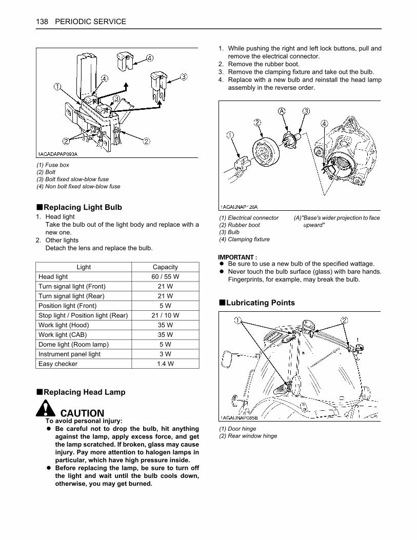
PERIODIC SERVICE138
BReplacing Light Bulb1. Head light
Take the bulb out of the light body and replace with anew one.
2. Other lightsDetach the lens and replace the bulb.
BReplacing Head Lamp
To avoid personal injury:A Be careful not to drop the bulb, hit anything
against the lamp, apply excess force, and getthe lamp scratched. If broken, glass may causeinjury. Pay more attention to halogen lamps inparticular, which have high pressure inside.
A Before replacing the lamp, be sure to turn offthe light and wait until the bulb cools down,otherwise, you may get burned.
1. While pushing the right and left lock buttons, pull andremove the electrical connector.
2. Remove the rubber boot.3. Remove the clamping fixture and take out the bulb.4. Replace with a new bulb and reinstall the head lamp
assembly in the reverse order.
A Be sure to use a new bulb of the specified wattage. A Never touch the bulb surface (glass) with bare hands.
Fingerprints, for example, may break the bulb.
BLubricating Points
(1) Fuse box(2) Bolt(3) Bolt fixed slow-blow fuse(4) Non bolt fixed slow-blow fuse
Light CapacityHead light 60 / 55 WTurn signal light (Front) 21 WTurn signal light (Rear) 21 WPosition light (Front) 5 WStop light / Position light (Rear) 21 / 10 WWork light (Hood) 35 WWork light (CAB) 35 WDome light (Room lamp) 5 WInstrument panel light 3 WEasy checker 1.4 W
(1) Electrical connector(2) Rubber boot(3) Bulb(4) Clamping fixture
(A)"Base's wider projection to face upward"
(1) Door hinge(2) Rear window hinge
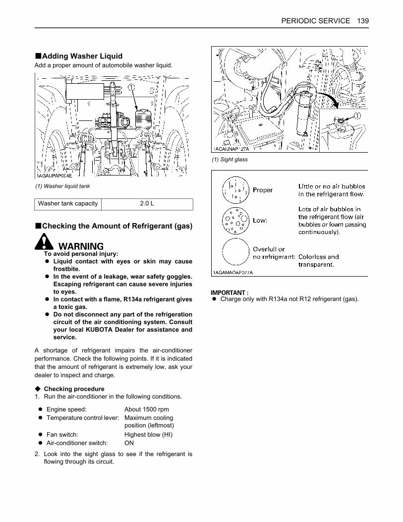
139PERIODIC SERVICE
BAdding Washer LiquidAdd a proper amount of automobile washer liquid.
BChecking the Amount of Refrigerant (gas)
To avoid personal injury:A Liquid contact with eyes or skin may cause
frostbite.A In the event of a leakage, wear safety goggles.
Escaping refrigerant can cause severe injuriesto eyes.
A In contact with a flame, R134a refrigerant givesa toxic gas.
A Do not disconnect any part of the refrigerationcircuit of the air conditioning system. Consultyour local KUBOTA Dealer for assistance andservice.
A shortage of refrigerant impairs the air-conditionerperformance. Check the following points. If it is indicatedthat the amount of refrigerant is extremely low, ask yourdealer to inspect and charge.
C Checking procedure1. Run the air-conditioner in the following conditions.
2. Look into the sight glass to see if the refrigerant isflowing through its circuit.
A Charge only with R134a not R12 refrigerant (gas).
(1) Washer liquid tank
Washer tank capacity 2.0 L
A Engine speed: About 1500 rpmA Temperature control lever: Maximum cooling
position (leftmost)A Fan switch: Highest blow (HI)A Air-conditioner switch: ON
(1) Sight glass
140 STORAGE
STORAGE
To avoid personal injury:A Do not clean the machine while the engine is
running.A To avoid the danger of exhaust fume
poisoning, do not operate the engine in aclosed building without proper ventilation.
A When storing, remove the key from the keyswitch to avoid unauthorized persons fromoperating the tractor and getting injured.
TRACTOR STORAGEIf you intend to store your tractor for an extended periodof time, follow the procedures outlined below.These procedures will insure that the tractor is ready tooperate with minimum preparation when it is removedfrom storage.1. Check the bolts and nuts for looseness, and tighten if
necessary.2. Apply grease to tractor areas where bare metal will
rust also to pivot areas.3. Detach the weights from the tractor body.4. Inflate the tires to a pressure a little higher than usual.5. Change the engine oil and run the engine to circulate
oil throughout the engine block and internal movingparts for about five minutes.
6. Keep the PTO clutch control switch or lever at"DISENGAGE" position while tractor is stored for along period of time.
7. With all implements lowered to the ground, coat anyexposed hydraulic cylinder piston rods with grease.
8. Park tractors equipped with the front suspensionsystem with the suspension cylinders in the lowestposition using manual control mode.
9. Remove the battery from the tractor. Store the batteryfollowing the battery storage procedures.(See "Checking Battery Condition" in "EVERY 100HOURS" in "PERIODIC SERVICE" section.)
10.Keep the tractor in a dry place where the tractor issheltered from the elements. Cover the tractor.
11.Store the tractor indoors in a dry area that is protectedfrom sunlight and excessive heat. If the tractor must bestored outdoors, cover it with a waterproof tarpaulin.Jack the tractor up and place blocks under the frontand rear axles so that all four tires are off the ground.Keep the tires out of direct sunlight and extreme heat.
A When washing the tractor, be sure to stop the engine.Allow sufficient time for the engine to cool beforewashing.
A Cover the tractor after the muffler and the engine havecooled down.
REMOVING THE TRACTOR FROM STORAGE1. Check the tire air pressure and inflate the tires if they
are low.2. Jack the tractor up and remove the support blocks
from under the front and rear axles.3. Install the battery. Before installing the battery, be sure
it is fully charged.4. Check the fan belt tension.5. Check all fluid levels (engine oil, transmission/
hydraulic oil, engine coolant and any attachedimplements).
6. Start the engine. Observe all gauges. If all gauges arefunctioning properly and reading normal, move thetractor outside. Once outside, park the tractor and letthe engine idle for at least five minutes. Shut theengine off and walk around tractor and make a visualinspection looking for evidence of oil or water leaks.
7. With the engine fully warmed up, release the parkingbrake and test the brakes for proper adjustment as youmove forward. Adjust the brakes as necessary.
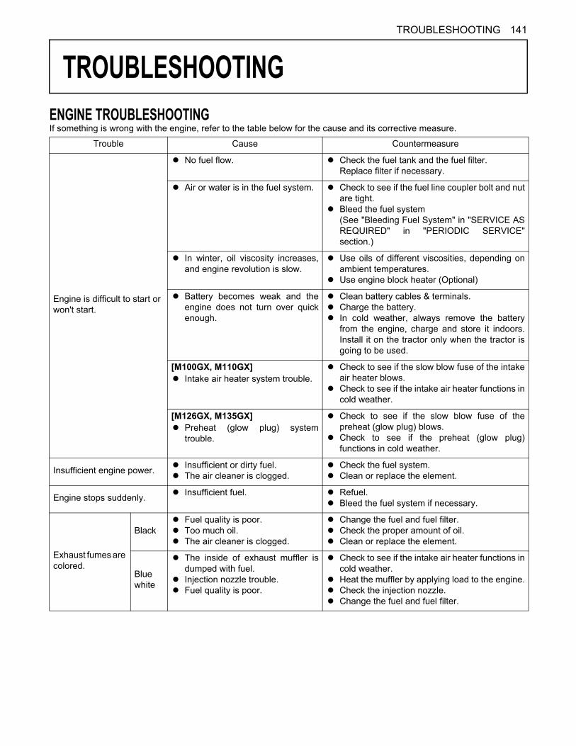
141TROUBLESHOOTING
TROUBLESHOOTING
ENGINE TROUBLESHOOTINGIf something is wrong with the engine, refer to the table below for the cause and its corrective measure.Trouble Cause Countermeasure
Engine is difficult to start or won't start.
A No fuel flow. A Check the fuel tank and the fuel filter.Replace filter if necessary.
A Air or water is in the fuel system. A Check to see if the fuel line coupler bolt and nutare tight.
A Bleed the fuel system(See "Bleeding Fuel System" in "SERVICE ASREQUIRED" in "PERIODIC SERVICE"section.)
A In winter, oil viscosity increases,and engine revolution is slow.
A Use oils of different viscosities, depending onambient temperatures.
A Use engine block heater (Optional)
A Battery becomes weak and theengine does not turn over quickenough.
A Clean battery cables & terminals.A Charge the battery.A In cold weather, always remove the battery
from the engine, charge and store it indoors.Install it on the tractor only when the tractor isgoing to be used.
[M100GX, M110GX]A Intake air heater system trouble.
A Check to see if the slow blow fuse of the intakeair heater blows.
A Check to see if the intake air heater functions incold weather.
[M126GX, M135GX]A Preheat (glow plug) system
trouble.
A Check to see if the slow blow fuse of thepreheat (glow plug) blows.
A Check to see if the preheat (glow plug)functions in cold weather.
Insufficient engine power. A Insufficient or dirty fuel.A The air cleaner is clogged.
A Check the fuel system.A Clean or replace the element.
Engine stops suddenly. A Insufficient fuel. A Refuel.A Bleed the fuel system if necessary.
Exhaust fumes are colored.
BlackA Fuel quality is poor.A Too much oil.A The air cleaner is clogged.
A Change the fuel and fuel filter.A Check the proper amount of oil.A Clean or replace the element.
Bluewhite
A The inside of exhaust muffler isdumped with fuel.
A Injection nozzle trouble.A Fuel quality is poor.
A Check to see if the intake air heater functions incold weather.
A Heat the muffler by applying load to the engine.A Check the injection nozzle.A Change the fuel and fuel filter.
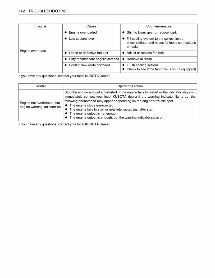
TROUBLESHOOTING142
If you have any questions, contact your local KUBOTA Dealer.
If you have any questions, contact your local KUBOTA Dealer.
Engine overheats
A Engine overloaded A Shift to lower gear or reduce load.
A Low coolant level A Fill cooling system to the correct level;check radiator and hoses for loose connectionsor leaks.
A Loose or defective fan belt A Adjust or replace fan belt.
A Dirty radiator core or grille screens A Remove all trash.
A Coolant flow route corroded A Flush cooling system.A Check to see if the fan drive is on. (if equipped)
Trouble Cause Countermeasure
Trouble Operator's action
Engine not overheated, but engine warning indicator on.
Stop the engine and get it restarted. If the engine fails to restart or the indicator stays on,immediately contact your local KUBOTA dealer.If the warning indicator lights up, thefollowing phenomena may appear depending on the engine's trouble spot.A The engine stops unexpected.A The engine fails to start or gets interrupted just after start.A The engine output is not enough.A The engine output is enough, but the warning indicator stays on.

143TROUBLESHOOTING
POWER SHIFT/RANGE SHIFT TROUBLE SHOOTINGIf something is wrong with the power shift / range shift, analarm sounds or the error code shown below is displayedon the liquid crystal display, indicating the location of thetrouble. If an error code appears, immediately contactyour local KUBOTA Dealer for repairs. Depending on theparts of the trouble, tractor can be used with somerestriction as emergency measure. For details, check theerror code and operator's action columns.
(1) Power shift number display area(2) Range shift position display area(3) Engine speed display area
Displayed error code
Alarm buzzer Condition Operator's actionPower shift number display area
Engine speed display
area
and
to flashing alternately
E-R51 3 consecutive tones
A Clutch is operated.A Hydraulic switch (master)
trouble.A Proportional solenoid valve
(master) trouble.
Contact your local KUBOTA Dealer. (If necessary, move the range shift lever to L. The machine can travel at any of 1st to 8th gears.)
and
to flashing alternately
E-R20 3 consecutive tones
A Trouble with the output voltageof the clutch pedal sensor.
A Clutch pedal sensor trouble.
Contact your local KUBOTA Dealer. (If necessary, move the range shift lever to N (in the L side) first and then to L. The machine can travel at any of 1st to 8th gears.)
flashing E-R37 3 consecutive tones
A Proportional solenoid valve(master) trouble.
Contact your local KUBOTA Dealer. (The machine cannot travel.)
--- --- --- A Shuttle switch (F/R) trouble.A Shuttle F/R is not displayed.
Contact your local KUBOTA Dealer. (The machine cannot travel.)
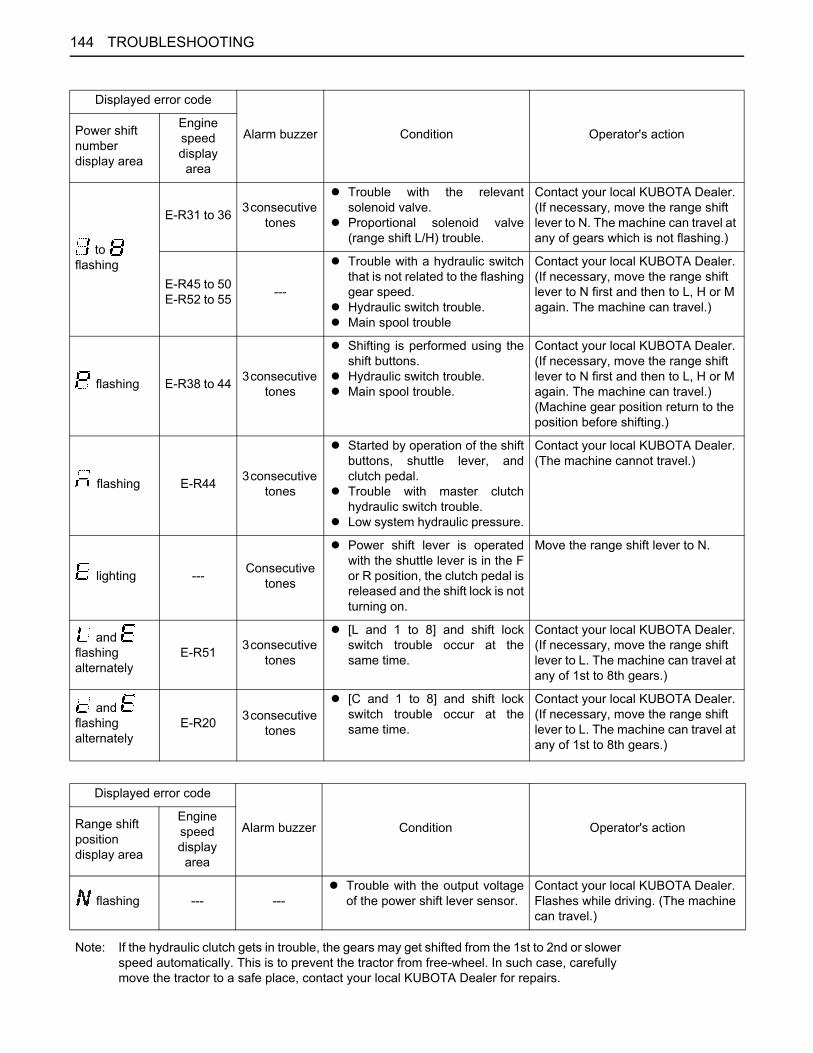
TROUBLESHOOTING144
Displayed error code
Alarm buzzer Condition Operator's actionPower shift number display area
Engine speed display
area
to flashing
E-R31 to 36 3 consecutive tones
A Trouble with the relevantsolenoid valve.
A Proportional solenoid valve(range shift L/H) trouble.
Contact your local KUBOTA Dealer. (If necessary, move the range shift lever to N. The machine can travel at any of gears which is not flashing.)
E-R45 to 50E-R52 to 55 ---
A Trouble with a hydraulic switchthat is not related to the flashinggear speed.
A Hydraulic switch trouble.A Main spool trouble
Contact your local KUBOTA Dealer. (If necessary, move the range shift lever to N first and then to L, H or M again. The machine can travel.)
flashing E-R38 to 44 3 consecutive tones
A Shifting is performed using theshift buttons.
A Hydraulic switch trouble.A Main spool trouble.
Contact your local KUBOTA Dealer. (If necessary, move the range shift lever to N first and then to L, H or M again. The machine can travel.) (Machine gear position return to the position before shifting.)
flashing E-R44 3 consecutive tones
A Started by operation of the shiftbuttons, shuttle lever, andclutch pedal.
A Trouble with master clutchhydraulic switch trouble.
A Low system hydraulic pressure.
Contact your local KUBOTA Dealer. (The machine cannot travel.)
lighting --- Consecutive tones
A Power shift lever is operatedwith the shuttle lever is in the For R position, the clutch pedal isreleased and the shift lock is notturning on.
Move the range shift lever to N.
and flashing alternately
E-R51 3 consecutive tones
A [L and 1 to 8] and shift lockswitch trouble occur at thesame time.
Contact your local KUBOTA Dealer. (If necessary, move the range shift lever to L. The machine can travel at any of 1st to 8th gears.)
and flashing alternately
E-R20 3 consecutive tones
A [C and 1 to 8] and shift lockswitch trouble occur at thesame time.
Contact your local KUBOTA Dealer. (If necessary, move the range shift lever to L. The machine can travel at any of 1st to 8th gears.)
Displayed error code
Alarm buzzer Condition Operator's actionRange shift position display area
Engine speed display
area
flashing --- ---A Trouble with the output voltage
of the power shift lever sensor.Contact your local KUBOTA Dealer. Flashes while driving. (The machine can travel.)
Note: If the hydraulic clutch gets in trouble, the gears may get shifted from the 1st to 2nd or slower speed automatically. This is to prevent the tractor from free-wheel. In such case, carefully move the tractor to a safe place, contact your local KUBOTA Dealer for repairs.
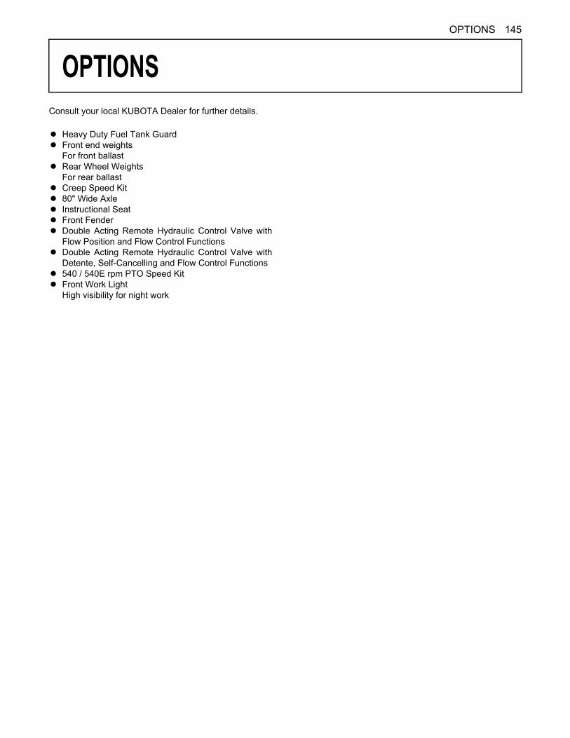
145OPTIONS
OPTIONS
Consult your local KUBOTA Dealer for further details.A Heavy Duty Fuel Tank GuardA Front end weights
For front ballastA Rear Wheel Weights
For rear ballastA Creep Speed KitA 80" Wide AxleA Instructional SeatA Front FenderA Double Acting Remote Hydraulic Control Valve with
Flow Position and Flow Control FunctionsA Double Acting Remote Hydraulic Control Valve with
Detente, Self-Cancelling and Flow Control FunctionsA 540 / 540E rpm PTO Speed KitA Front Work Light
High visibility for night work
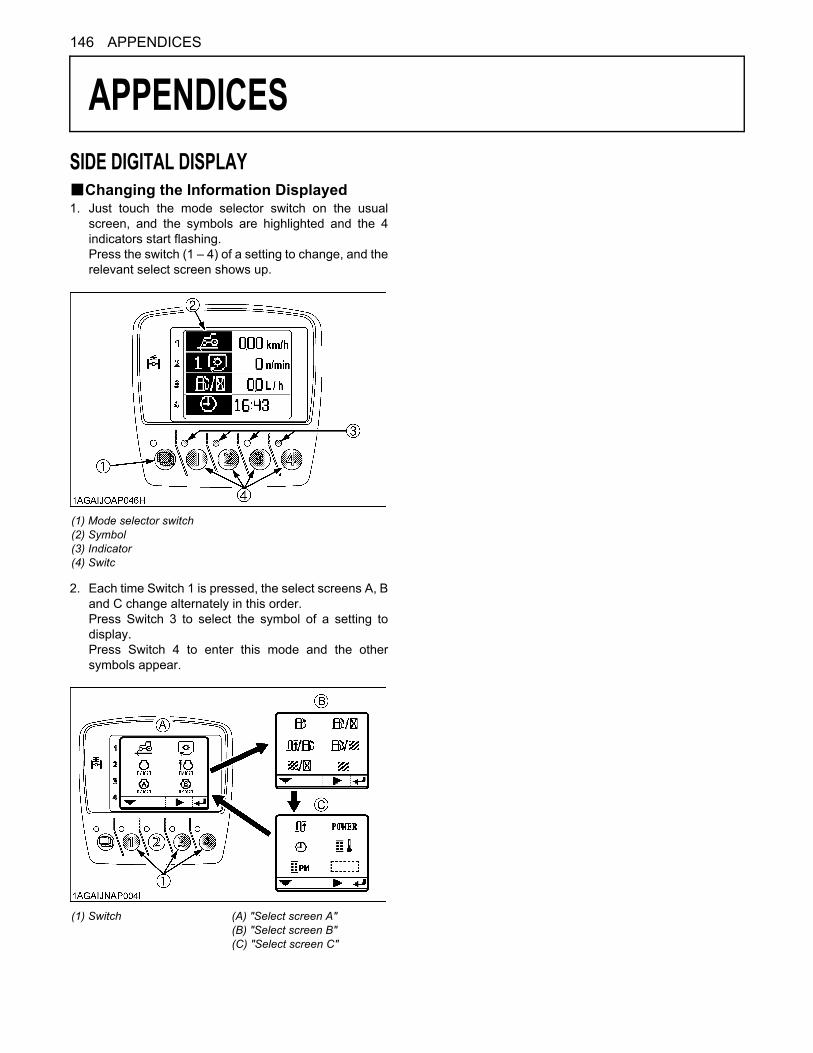
146 APPENDICES
APPENDICES
SIDE DIGITAL DISPLAYBChanging the Information Displayed1. Just touch the mode selector switch on the usualscreen, and the symbols are highlighted and the 4indicators start flashing.Press the switch (1 – 4) of a setting to change, and therelevant select screen shows up.
2. Each time Switch 1 is pressed, the select screens A, Band C change alternately in this order.Press Switch 3 to select the symbol of a setting todisplay.Press Switch 4 to enter this mode and the othersymbols appear.
(1) Mode selector switch(2) Symbol(3) Indicator(4) Switc
(1) Switch (A) "Select screen A"(B) "Select screen B"(C) "Select screen C"

147APPENDICES
BInformation Displayed and its Handling
Selected screen Info Display Remarks Ref.
page
A
Travelspeed
Travel speed A Shows the standard factory settings. Refer to the"Handling the side digital display" section.
35
Average travel speed
35
PTO
PTO rpm (Shift 1) A Shows the standard factory settings. Refer to the"Handling the side digital display" section.
66
PTO rpm (Shift 2)
66
Enginerpm -
Upper-limit rpmsetting
47
MemoryA rpm 47
MemoryB rpm 47
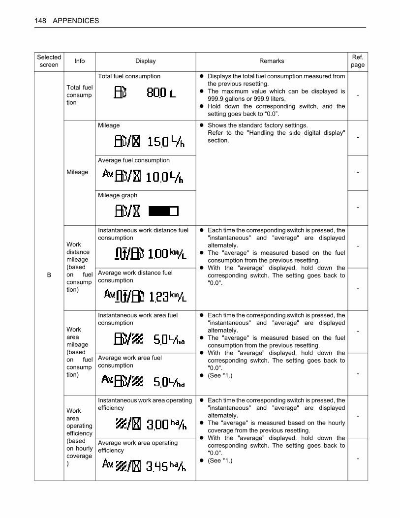
APPENDICES148
Selected screen Info Display Remarks Ref.
page
B
Total fuelconsumption
Total fuel consumption A Displays the total fuel consumption measured fromthe previous resetting.
A The maximum value which can be displayed is999.9 gallons or 999.9 liters.
A Hold down the corresponding switch, and thesetting goes back to “0.0”.
-
Mileage
Mileage A Shows the standard factory settings.Refer to the "Handling the side digital display"section. -
Average fuel consumption
-
Mileage graph
-
Workdistancemileage(basedon fuelconsumption)
Instantaneous work distance fuel consumption
A Each time the corresponding switch is pressed, the"instantaneous" and "average" are displayedalternately.
A The "average" is measured based on the fuelconsumption from the previous resetting.
A With the "average" displayed, hold down thecorresponding switch. The setting goes back to"0.0".
-
Average work distance fuel consumption
-
Workareamileage(basedon fuelconsumption)
Instantaneous work area fuel consumption
A Each time the corresponding switch is pressed, the"instantaneous" and "average" are displayedalternately.
A The "average" is measured based on the fuelconsumption from the previous resetting.
A With the "average" displayed, hold down thecorresponding switch. The setting goes back to"0.0".
A (See *1.)
-
Average work area fuel consumption
-
Workareaoperatingefficiency(basedon hourlycoverage)
Instantaneous work area operating efficiency
A Each time the corresponding switch is pressed, the"instantaneous" and "average" are displayedalternately.
A The "average" is measured based on the hourlycoverage from the previous resetting.
A With the "average" displayed, hold down thecorresponding switch. The setting goes back to"0.0".
A (See *1.)
-
Average work area operating efficiency
-

149APPENDICES
*1: In the various setting mode, preset the "Working range of implement". (Refer to the "Initial Setting" in "SIDE DIGITAL DISPLAY" in "OPERATING THE TRACTOR" section.) If not preset, correctly, incorrect data will be displayed.
Selected screen Info Display Remarks Ref.
page
B Workarea
A Displays the work area measured from theprevious resetting.
A Hold down the corresponding switch. The settinggoes back to "0.0".
A (See *1.)
-
Selected screen Info Display Remarks Ref.
page
C
Traveldistance
A Displays the travel distance measured from theprevious resetting.
A Hold down the corresponding switch, and thesetting goes back to “0”.
-
Loadingfactor
Instantaneous loading factor A Each time the corresponding switch is pressed, the“instantaneous”, “average” and “graph” aredisplayed alternately in this order.
A The “average” is measured based on the loadingfactor from the previous resetting.
A With the “average” displayed, hold down thecorresponding switch. The setting goes back to“0”.
A The “instantaneous loading factor graph”graphically displays the instantaneous loadingfactor in real time. (The more the bar is extendedto the right, the higher the load becomes.)
-
Average loading factor
-
Instantaneous loading factor graph
-
Clock
Time A Shows the standard factory settings. Refer to the“Handling the side digital display” section.
42
Date
152
DPFtempera-ture
A Displays the DPF muffler temperature.14
PMbuildup
PM buildup A Displays the PM buildup inside the DPF muffler.A Regeneration is needed when the 100% level has
been reached.A Each time the corresponding switch is pressed, the
“numerical value” and “graph” are displayedalternately.
A The more the bar is extended to the right, the morePM builds up.
14
PM buildup graph
14
BlankA Used to delete the information displayed.
-
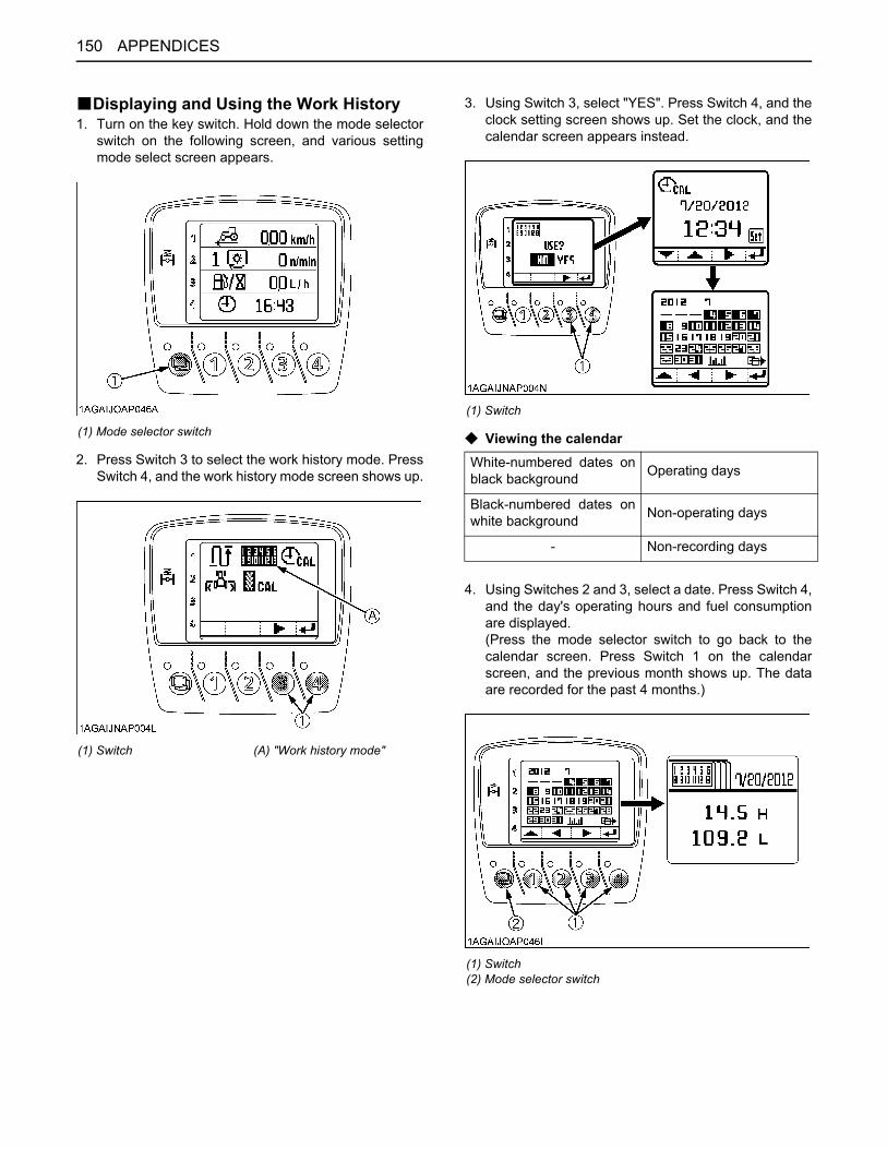
APPENDICES150
BDisplaying and Using the Work History1. Turn on the key switch. Hold down the mode selector
switch on the following screen, and various settingmode select screen appears.
2. Press Switch 3 to select the work history mode. PressSwitch 4, and the work history mode screen shows up.
3. Using Switch 3, select "YES". Press Switch 4, and theclock setting screen shows up. Set the clock, and thecalendar screen appears instead.
C Viewing the calendar
4. Using Switches 2 and 3, select a date. Press Switch 4,and the day's operating hours and fuel consumptionare displayed. (Press the mode selector switch to go back to thecalendar screen. Press Switch 1 on the calendarscreen, and the previous month shows up. The dataare recorded for the past 4 months.)
(1) Mode selector switch
(1) Switch (A) "Work history mode"
(1) Switch
White-numbered dates onblack background Operating days
Black-numbered dates onwhite background Non-operating days
- Non-recording days
(1) Switch(2) Mode selector switch
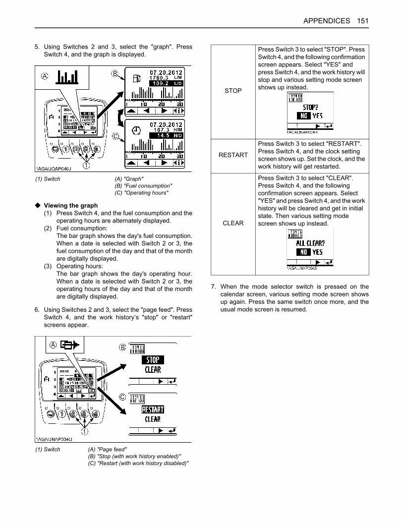
151APPENDICES
5. Using Switches 2 and 3, select the "graph". PressSwitch 4, and the graph is displayed.
C Viewing the graph(1) Press Switch 4, and the fuel consumption and the
operating hours are alternately displayed.(2) Fuel consumption:
The bar graph shows the day's fuel consumption.When a date is selected with Switch 2 or 3, thefuel consumption of the day and that of the monthare digitally displayed.
(3) Operating hours:The bar graph shows the day's operating hour.When a date is selected with Switch 2 or 3, theoperating hours of the day and that of the monthare digitally displayed.
6. Using Switches 2 and 3, select the "page feed". PressSwitch 4, and the work history’s "stop" or "restart"screens appear.
7. When the mode selector switch is pressed on thecalendar screen, various setting mode screen showsup again. Press the same switch once more, and theusual mode screen is resumed.
(1) Switch (A) "Graph"(B) "Fuel consumption"(C) "Operating hours"
(1) Switch (A) "Page feed"(B) "Stop (with work history enabled)"(C) "Restart (with work history disabled)"
STOP
Press Switch 3 to select "STOP". Press Switch 4, and the following confirmation screen appears. Select "YES" and press Switch 4, and the work history will stop and various setting mode screen shows up instead.
RESTART
Press Switch 3 to select "RESTART". Press Switch 4, and the clock setting screen shows up. Set the clock, and the work history will get restarted.
CLEAR
Press Switch 3 to select "CLEAR". Press Switch 4, and the following confirmation screen appears. Select "YES" and press Switch 4, and the work history will be cleared and get in initial state. Then various setting mode screen shows up instead.
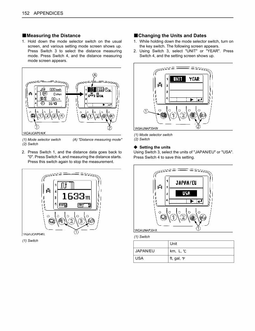
APPENDICES152
BMeasuring the Distance1. Hold down the mode selector switch on the usual
screen, and various setting mode screen shows up.Press Switch 3 to select the distance measuringmode. Press Switch 4, and the distance measuringmode screen appears.
2. Press Switch 1, and the distance data goes back to"0". Press Switch 4, and measuring the distance starts.Press this switch again to stop the measurement.
BChanging the Units and Dates1. While holding down the mode selector switch, turn on
the key switch. The following screen appears.2. Using Switch 3, select "UNIT" or "YEAR". Press
Switch 4, and the setting screen shows up.
C Setting the unitsUsing Switch 3, select the units of "JAPAN/EU" or "USA".Press Switch 4 to save this setting.
(1) Mode selector switch(2) Switch
(A) "Distance measuring mode"
(1) Switch
(1) Mode selector switch(2) Switch
(1) Switch
Unit
JAPAN/EU km, L,
USA ft, gal,
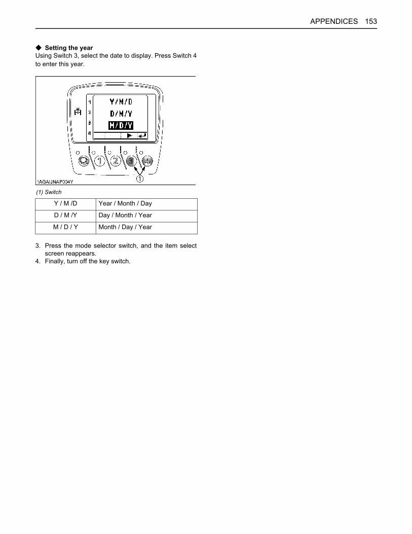
153APPENDICES
C Setting the yearUsing Switch 3, select the date to display. Press Switch 4to enter this year.
3. Press the mode selector switch, and the item selectscreen reappears.
4. Finally, turn off the key switch.
(1) Switch
Y / M /D Year / Month / Day
D / M /Y Day / Month / Year
M / D / Y Month / Day / Year
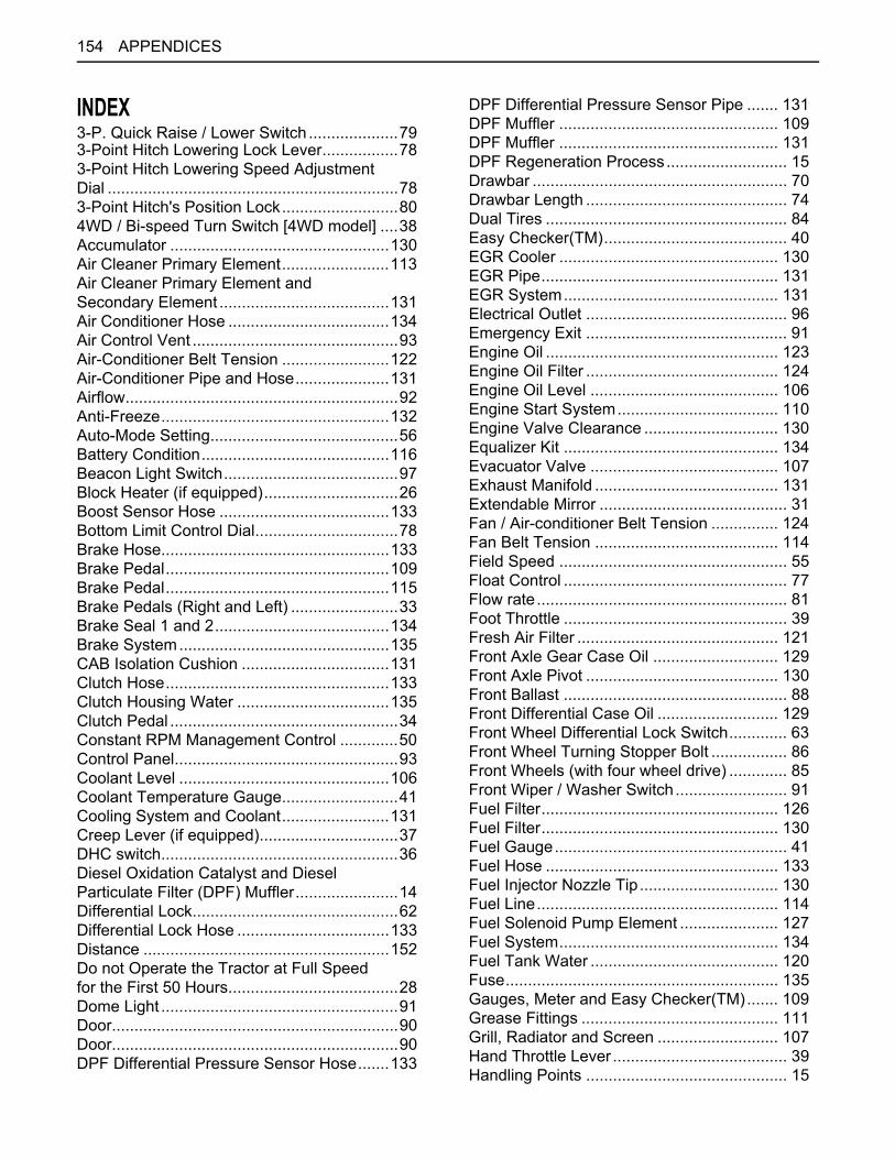
APPENDICES154
INDEX3-P. Quick Raise / Lower Switch ....................793-Point Hitch Lowering Lock Lever.................783-Point Hitch Lowering Speed Adjustment Dial .................................................................783-Point Hitch's Position Lock..........................804WD / Bi-speed Turn Switch [4WD model] ....38Accumulator .................................................130Air Cleaner Primary Element........................113Air Cleaner Primary Element and Secondary Element ......................................131Air Conditioner Hose ....................................134Air Control Vent ..............................................93Air-Conditioner Belt Tension ........................122Air-Conditioner Pipe and Hose.....................131Airflow.............................................................92Anti-Freeze...................................................132Auto-Mode Setting..........................................56Battery Condition..........................................116Beacon Light Switch.......................................97Block Heater (if equipped)..............................26Boost Sensor Hose ......................................133Bottom Limit Control Dial................................78Brake Hose...................................................133Brake Pedal..................................................109Brake Pedal..................................................115Brake Pedals (Right and Left) ........................33Brake Seal 1 and 2.......................................134Brake System...............................................135CAB Isolation Cushion .................................131Clutch Hose..................................................133Clutch Housing Water ..................................135Clutch Pedal ...................................................34Constant RPM Management Control .............50Control Panel..................................................93Coolant Level ...............................................106Coolant Temperature Gauge..........................41Cooling System and Coolant........................131Creep Lever (if equipped)...............................37DHC switch.....................................................36Diesel Oxidation Catalyst and Diesel Particulate Filter (DPF) Muffler.......................14Differential Lock..............................................62Differential Lock Hose ..................................133Distance .......................................................152Do not Operate the Tractor at Full Speed for the First 50 Hours......................................28Dome Light .....................................................91Door................................................................90Door................................................................90DPF Differential Pressure Sensor Hose.......133
DPF Differential Pressure Sensor Pipe ....... 131DPF Muffler ................................................. 109DPF Muffler ................................................. 131DPF Regeneration Process........................... 15Drawbar ......................................................... 70Drawbar Length ............................................. 74Dual Tires ...................................................... 84Easy Checker(TM)......................................... 40EGR Cooler ................................................. 130EGR Pipe..................................................... 131EGR System................................................ 131Electrical Outlet ............................................. 96Emergency Exit ............................................. 91Engine Oil .................................................... 123Engine Oil Filter ........................................... 124Engine Oil Level .......................................... 106Engine Start System.................................... 110Engine Valve Clearance .............................. 130Equalizer Kit ................................................ 134Evacuator Valve .......................................... 107Exhaust Manifold ......................................... 131Extendable Mirror .......................................... 31Fan / Air-conditioner Belt Tension ............... 124Fan Belt Tension ......................................... 114Field Speed ................................................... 55Float Control .................................................. 77Flow rate........................................................ 81Foot Throttle .................................................. 39Fresh Air Filter ............................................. 121Front Axle Gear Case Oil ............................ 129Front Axle Pivot ........................................... 130Front Ballast .................................................. 88Front Differential Case Oil ........................... 129Front Wheel Differential Lock Switch............. 63Front Wheel Turning Stopper Bolt ................. 86Front Wheels (with four wheel drive) ............. 85Front Wiper / Washer Switch ......................... 91Fuel Filter..................................................... 126Fuel Filter..................................................... 130Fuel Gauge.................................................... 41Fuel Hose .................................................... 133Fuel Injector Nozzle Tip............................... 130Fuel Line...................................................... 114Fuel Solenoid Pump Element ...................... 127Fuel System................................................. 134Fuel Tank Water .......................................... 120Fuse............................................................. 135Gauges, Meter and Easy Checker(TM)....... 109Grease Fittings ............................................ 111Grill, Radiator and Screen ........................... 107Hand Throttle Lever ....................................... 39Handling Points ............................................. 15

155APPENDICES
Head Lamp...................................................138Head Light, Turn Signal / Hazard Light etc. .109Holes of Lower Links ......................................70Hood.............................................................104Horn Button ....................................................32Hour / Trip Monitor .........................................41Hydraulic Control Unit Use Reference Chart..83Hydraulic Oil Filter ........................................122Immediately Stop the Engine if:......................39Inflation Pressure ...........................................84Information Displayed...................................146Information Displayed and its Handling........147Initial Setting...................................................42Inner Air Filter...............................................121Instructional Seat............................................30Intake Air Heater ..........................................131Intake Air Line ..............................................119Intake Air Line ..............................................133King-pin Pivot ...............................................130Lateral Float ...................................................70Lift Arm Top Limit Adjustment Dial .................78Lift Cylinder Hose.........................................134Lifting Rod (Left).............................................71Lifting Rod (Right) ..........................................71Light Bulb .....................................................138Light Switch ....................................................31Lubricating Points.........................................138Manual Control Mode .....................................61Master Cylinder Kit .......................................134Mixed Draft Control Mode ..............................77Mode Selector Switch.....................................76Movable Parts ..............................................109Oil Cooler Line..............................................119Oil Cooler Line..............................................133Oil for New Tractors .......................................28Operating on Slopes and Rough Terrain........64Operating the Tractor on a Road....................64Operation........................................................53Operation........................................................94Operator's Seat ..............................................28Outline ............................................................51Outline ............................................................59Parking ...........................................................62Parking Brake Cable ....................................133Parking Brake Lever.......................................39Parking Brake Lever.....................................115PM Warning Level and Required Procedures 18PM Warning Level and Required Procedures 20Position Control Mode ....................................76Power Shift / Range Shift Lever (PS. Lever) ..35Power Steering...............................................64Power Steering Hose ...................................133
Power Steering Line .................................... 119Pre-Fuel Filter .............................................. 126PTO Clutch Control Switch............................ 66PTO Gear Shift Lever .................................... 67PTO Gear Shift Lever .................................... 68PTO Shaft Cover and Shaft Cap ................... 68Quick Hitch (Hook type)................................. 72Radiator Hose (Water pipes) ....................... 133Radiator Hose and Clamp ........................... 117Rear Ballast ................................................... 89Rear Wheel Differential Lock Pedal............... 63Rear Wheels.................................................. 87Rear Window ................................................. 90Rear Wiper / Washer Switch ......................... 92Refrigerant (gas).......................................... 139Refueling ..................................................... 105Regeneration Operating Procedure............... 17Regeneration Operating Procedure............... 19Remote Control Valve ................................... 80Remote Control Valve Coupler Connecting and Disconnecting ......................................... 81Remote Control Valve Lever ......................... 80Remote Couplers Spillage Collector.............. 82Remote Hitch UP / DOWN Switch ................. 71Rev-limiter Control Dial.................................. 39Rev-limiter Control Setting............................. 47Ride Condition Damper Switch...................... 61RPM Dual Memory Setting ............................ 47Screen Display .............................................. 44Seat Belt ........................................................ 30Seat Belt ...................................................... 109Sensitivity Adjustment ................................... 56Shuttle Lever ................................................. 37Side Cover................................................... 104Slow-Blow Fuses ......................................... 137Steering Adjustment ...................................... 31Stopping ........................................................ 39Sun Roof........................................................ 91Supply Pump ............................................... 130Suspension Hose ........................................ 134Suspension Switch ........................................ 59Swing Drawbar .............................................. 74Tachometer ................................................... 41Telescopic Stabilizers .................................... 72Terminology................................................... 75Tie-rod Dust Cover ...................................... 111Tips on DPF Regeneration ............................ 21Toe-in .......................................................... 120Top Link......................................................... 72Top Link Mounting Holes............................... 70Trailer Connector ........................................... 32Trailer Electrical Outlet .................................. 65

APPENDICES156
Transmission Fluid .......................................128Transmission Fluid Level..............................106Transport the Tractor Safely...........................64Turbocharger................................................130Turn Signal / Hazard Light Switch ..................31Units and Dates............................................152Walk Around Inspection ...............................105Warm-up and Transmission Oil at Low Temperature Range .......................................26Washer Liquid ..............................................139Water Separator ...........................................105Water Separator ...........................................126Wheel Bolt Torque........................................111Wipers in Cold Season...................................92Work History.................................................150Work Light Switch (Front)...............................32Work Light Switch (Rear) ...............................32Work Speed Display.......................................54