operator´s manual rider 16 - hsqglobal€¦ · never carry passengers. read the operator’s...
TRANSCRIPT

Operator´s manual
Rider 16
Please read these instructions carefully and make sureyou understand them before using the machine. English

Svenska – 31
Sve-5 225/232/235 Bruk 97-11-25, 08.4631
English – 1
Operator’s Manual forRider 16
CONTENTS
Introduction ......................................................... 2Driving and transport on public roads .............. 2Towing .............................................................. 2Use ................................................................... 2Serial number ................................................... 3
Explanation of symbols ...................................... 4Safety instructions .............................................. 5
General Use ..................................................... 5Driving on Slopes ............................................. 7Children ............................................................ 8Maintenance .................................................... 8Transport ........................................................ 10
Presentation ...................................................... 11Location of the controls .................................. 11Throttle/Choke lever ....................................... 12Speed limiter .................................................. 12Parking brake ................................................. 12Cutting unit ..................................................... 13Lift lever for cutting unit .................................. 13Lever for adjustment of cutting height ............ 14Seat ................................................................ 14Fuelling .......................................................... 14
Driving ................................................................ 15Before starting ................................................ 15Starting the engine ......................................... 15Driving the machine ....................................... 15Cutting tips ..................................................... 18Stopping the engine ....................................... 19Release lever ................................................. 19
Maintenance ...................................................... 20Maintenance schedule ................................... 20Dismantling of the machine hoods ................. 21Checking and adjusting the steering wires .... 22
Adjusting the brake ........................................ 22Checking and adjustment of throttle wire ....... 23Replacement of fuel filter ............................... 23Replacement of air filter ................................. 24Checking the fuel pump’s air filter .................. 25Checking the battery acid level ...................... 25Ignition System .............................................. 25Checking the safety system ........................... 26Checking the tyre pressure ............................ 27Checking the engine’s cooling air intake ........ 27Fitting the cutting unit ..................................... 28Installing BioClip 90 ....................................... 28Checking and adjustment of cutting unit’sground pressure ............................................. 29Checking the parallelism of the cutting unit .... 29Adjusting the parallelism of the cutting unit .... 30Dismantling the cutting unit ............................ 30Replacing the cutting unit belts ...................... 31Service position for cutting unit ...................... 33Checking the blades ....................................... 36Replacing the break-pin (BioClip) .................. 37
Lubrication ......................................................... 38Checking the engine’s oil level ....................... 38Changing the oil ............................................. 38Checking the transmission’s oil level .............. 39Lubricating the belt adjuster ........................... 39General lubrication ......................................... 39
Trouble shooting schedule ............................... 40Storage ............................................................... 41
Winter storage ................................................ 41Service ........................................................... 41
Technical data ................................................... 42EU Declaration of Conformity .......................... 43
IMPORTANT INFORMATION
Read carefully through the Operator’smanual so that you know how to use andmaintain the Rider before you use it.
For service measures other than thosedescribed in this manual, please contactan authorised dealer that provides partsand service.

2 – English
INSTRUCTION
Dear customer
Thank you for choosing a Husqvarna Rider. Husqvarna Riders are built to a unique design with a front-mounted cutting unit and a patented rear-wheel steering system. Riders are designed for maximum efficiencyeven in small or confined areas. The closely grouped controls and pedal-operated hydrostatic transmissionalso contribute to the performance of this machine.
We hope you will find this operator’s manual very useful. By following its instructions (on operation, service,maintenance, etc.) you will significantly extend the life of the machine and even its second-hand value.
When you sell your Rider, make sure you pass on the operator’s manual to the new owner.
Travel and transport on public roads
Check the relevant road traffic regulations before driving the machine on a public road. If transporting themachine on another vehicle always use approved securing devices and make sure that the machine issecurely held.
Towing
When your machine is equipped with a hydrostatic transmission you should, if necessary, only tow themachine over short distances and at a low speed, otherwise there is a risk of damaging the transmission.
Intended use
This machine is designed solely for cutting grass on conventional lawns and other cleared and leveledground without obstacles, as rocks, stumps etc., and, in conjunction with accessories supplied by themanufacturer even for other special tasks for which instructions are delivered with the accessory. Use in anyother way is considered as contrary to the intended use. Compliance with and strict adherence to theconditions of operation, service and repair as specified by the manufacturer also constitute essentialelements of the intended use.
This machine should be operated, serviced and repaired only by persons who are familiar with its particularcharacteristics and who are acquainted with the relevant safety procedures.
Accident prevention regulations, all other generally recognised regulations on safety and occupationalmedicine, and all road traffic regulations must be observed at all times.
Any arbitrary modifications carried out to this machine may relieve the manufacturer of liability for anyresulting damage or injury
English – 3
SAFETY INSTRUCTIONS
Good service
Husqvarna products are sold all over the world and only through servicing dealers. This is to ensure that you,the customer, get the best support and service. Before the machine is delivered it undergoes inspection andis adjusted by your dealer.
When you need spare parts or advice on service issues, warranty terms, etc., contact:
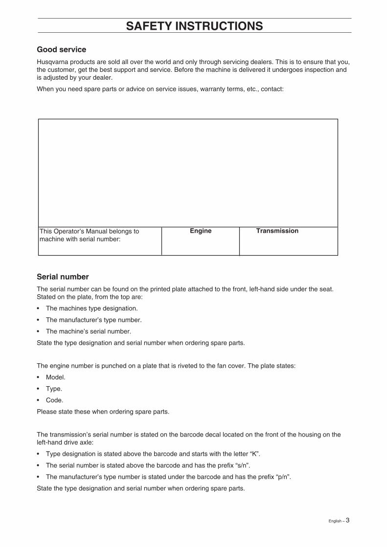
This Operator’s Manual belongs tomachine with serial number:
Serial number
The serial number can be found on the printed plate attached to the front, left-hand side under the seat.Stated on the plate, from the top are:
• The machines type designation.
• The manufacturer’s type number.
• The machine’s serial number.
State the type designation and serial number when ordering spare parts.
The engine number is punched on a plate that is riveted to the fan cover. The plate states:
• Model.
• Type.
• Code.
Please state these when ordering spare parts.
The transmission’s serial number is stated on the barcode decal located on the front of the housing on theleft-hand drive axle:
• Type designation is stated above the barcode and starts with the letter “K”.
• The serial number is stated above the barcode and has the prefix “s/n”.
• The manufacturer’s type number is stated under the barcode and has the prefix “p/n”.
State the type designation and serial number when ordering spare parts.
Engine Transmission

4 – English
These symbols are on the machine and in the operator’s manual.Study them carefully so that you know what they mean.
Read the operator’s manual
Reverse Neutral Fast Slow Engine off Battery Choke Fuel
Oil pressure Cutting height Backwards Forwards Ignition
Hydrostatic free wheel Use eye and hearing protection Parking brake Brake Warning
Never use the machine if persons, especiallychildren, or animals, are in the vicinity.
Starting instructionsRead the instructionsCheck the engine’s oil levelCheck the hydrostat’s oil levelLift up the cutting unitPut the hydrostat pedals in theneutral positionBrakeIf the engine is cold use the chokeStart the engineRelease the parking brake beforedriving
Drive very slowlywithout the cutting unit.
Keep hands and feet awayfrom under the hood when
the engine is running.
NR
EXPLANATION OF SYMBOLS
Speed limiter pedal forwards
Neutral
Speed limiter pedal reverse
Switch off the engine and take offthe ignition cable before repairs ormaintenance
Never carry passengers on themachine or equipment.
Noise emission to surroundings in accordancewith the directive of the European Community.
The machine’s emission is indicated in thechapter TECHNICAL DATA and on the decal.
CE conformitymarking
Warning!Risk that the
machine can tip over
Never drive across aslope
Warning!Rotating blades.
English – 5
8010-047
6003-002
8010-052
Safety instructions
General use
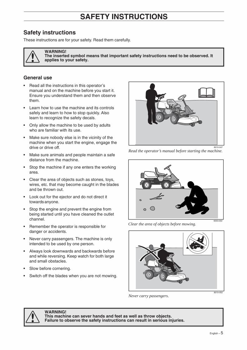
• Read all the instructions in this operator’smanual and on the machine before you start it.Ensure you understand them and then observethem.
• Learn how to use the machine and its controlssafely and learn to how to stop quickly. Alsolearn to recognize the safety decals.
• Only allow the machine to be used by adultswho are familiar with its use.
• Make sure nobody else is in the vicinity of themachine when you start the engine, engage thedrive or drive off.
• Make sure animals and people maintain a safedistance from the machine.
• Stop the machine if any one enters the workingarea.
• Clear the area of objects such as stones, toys,wires, etc. that may become caught in the bladesand be thrown out.
• Look out for the ejector and do not direct ittowards anyone.
• Stop the engine and prevent the engine frombeing started until you have cleaned the outletchannel.
• Remember the operator is responsible fordanger or accidents.
• Never carry passengers. The machine is onlyintended to be used by one person.
• Always look downwards and backwards beforeand while reversing. Keep watch for both largeand small obstacles.
• Slow before cornering.
• Switch off the blades when you are not mowing.
SAFETY INSTRUCTIONS
WARNING!This machine can sever hands and feet as well as throw objects.Failure to observe the safety instructions can result in serious injuries.
WARNING!The inserted symbol means that important safety instructions need to be observed. Itapplies to your safety.
Never carry passengers.
Read the operator’s manual before starting the machine.
Clear the area of objects before mowing.
These instructions are for your safety. Read them carefully.

6 – English
6003-006
8011-292
• Take care when rounding a fixed object, so thatthe blades do not hit it. Never run the machineover foreign objects.
• Only use the machine in daylight or in otherwell-lit conditions. Keep the machine at a safedistance from holes or other irregularities in theground. Pay attention to other possible risks.
• Never use the machine if you are tired, if youhave consumed alcohol, or if you are takingother drugs or medication that can affect yourvision, judgment or co-ordination.
• Keep an eye on the traffic when working close toa road or when crossing it.
• Never leave the machine unsupervised with theengine running. Always stop the blades, applythe parking brake, stop the engine and removethe keys before leaving the machine.
• Never allow children or other persons nottrained in the use of the machine to use orservice it. Local laws may regulate the age ofthe user.
SAFETY INSTRUCTIONS
WARNING!Engine exhaust, some of itsconstituents and certain vehiclecomponents contain or emitchemicals considered to causecancer, birth defects or otherreproductive impairment. Theengine emits carbon monoxide,which is a colourless, poisonousgas. Do not use the machine inenclosed spaces.
WARNING!You must use approved personal protective equipment whenever you use the ma-chine. Personal protective equipment cannot eliminate the risk of injury but it willreduce the degree of injury if an accident does happen. Ask your dealer for help inchoosing the right equipment.
• Make sure that you have first aid equipmentclose at hand when using the machine.
• Never use the machine when barefoot. Alwayswear protective shoes or protective boots,preferably with steel toes.
• Wear approved protective glasses or full-facevisor during assembly and when operating.
• Never wear loose fitting clothes that can catch inmoving parts.
Keep children away from the area to be mowed.
Personal protective equipment.
English – 7
8010-054
6003-004
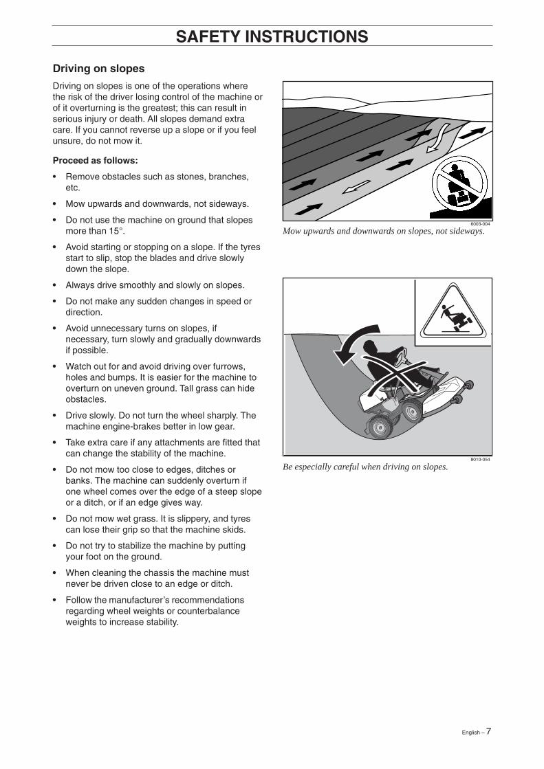
Be especially careful when driving on slopes.
Mow upwards and downwards on slopes, not sideways.
Driving on slopes
Driving on slopes is one of the operations wherethe risk of the driver losing control of the machine orof it overturning is the greatest; this can result inserious injury or death. All slopes demand extracare. If you cannot reverse up a slope or if you feelunsure, do not mow it.
Proceed as follows:
• Remove obstacles such as stones, branches,etc.
• Mow upwards and downwards, not sideways.
• Do not use the machine on ground that slopesmore than 15°.
• Avoid starting or stopping on a slope. If the tyresstart to slip, stop the blades and drive slowlydown the slope.
• Always drive smoothly and slowly on slopes.
• Do not make any sudden changes in speed ordirection.
• Avoid unnecessary turns on slopes, ifnecessary, turn slowly and gradually downwardsif possible.
• Watch out for and avoid driving over furrows,holes and bumps. It is easier for the machine tooverturn on uneven ground. Tall grass can hideobstacles.
• Drive slowly. Do not turn the wheel sharply. Themachine engine-brakes better in low gear.
• Take extra care if any attachments are fitted thatcan change the stability of the machine.
• Do not mow too close to edges, ditches orbanks. The machine can suddenly overturn ifone wheel comes over the edge of a steep slopeor a ditch, or if an edge gives way.
• Do not mow wet grass. It is slippery, and tyrescan lose their grip so that the machine skids.
• Do not try to stabilize the machine by puttingyour foot on the ground.
• When cleaning the chassis the machine mustnever be driven close to an edge or ditch.
• Follow the manufacturer’s recommendationsregarding wheel weights or counterbalanceweights to increase stability.
SAFETY INSTRUCTIONS

8 – English
8010-057
8010-058
Children
• Serious accidents may occur if you fail to be onyour guard for children in the vicinity of themachine. Children are often attracted to themachine and mowing. Never assume thatchildren will remain where you last saw them.
• Keep children away from the area to be mowedand under close supervision by another adult.
• Keep an eye out and shut off the machine ifchildren enter the work area.
• Before and during reversing procedures, lookbehind you and down for small children.
• Never allow children to ride along. They can falloff and seriously injure themselves or be in theway for safe manoeuvring of the machine.
• Never allow children to operate the machine.
• Be particularly careful near corners, bushes,trees or other objects that block your view.
SAFETY INSTRUCTIONS
Never allow children to operate the machine.
Never fill the fuel tank indoors.
Maintenance
• Stop the engine. Prevent starting by removingthe ignition cable from the spark plug or removethe ignition key before making any adjustmentsor carrying out maintenance.
• Never fill the fuel tank indoors.
• Petrol and petrol fumes are poisonous andextremely flammable. Be especially careful whenhandling petrol, as carelessness can result inpersonal injury or fire.
• Only store fuel in containers approved for thepurpose.
• Never remove the fuel cap and fill the petroltank while the engine is running.
• Allow the engine to cool before refuelling. Donot smoke. Do not fill petrol in the vicinity ofsparks or naked flames.
English – 9
WARNING!The engine and the exhaustsystem become very hot duringoperation.Risk of burn injuries if touched.
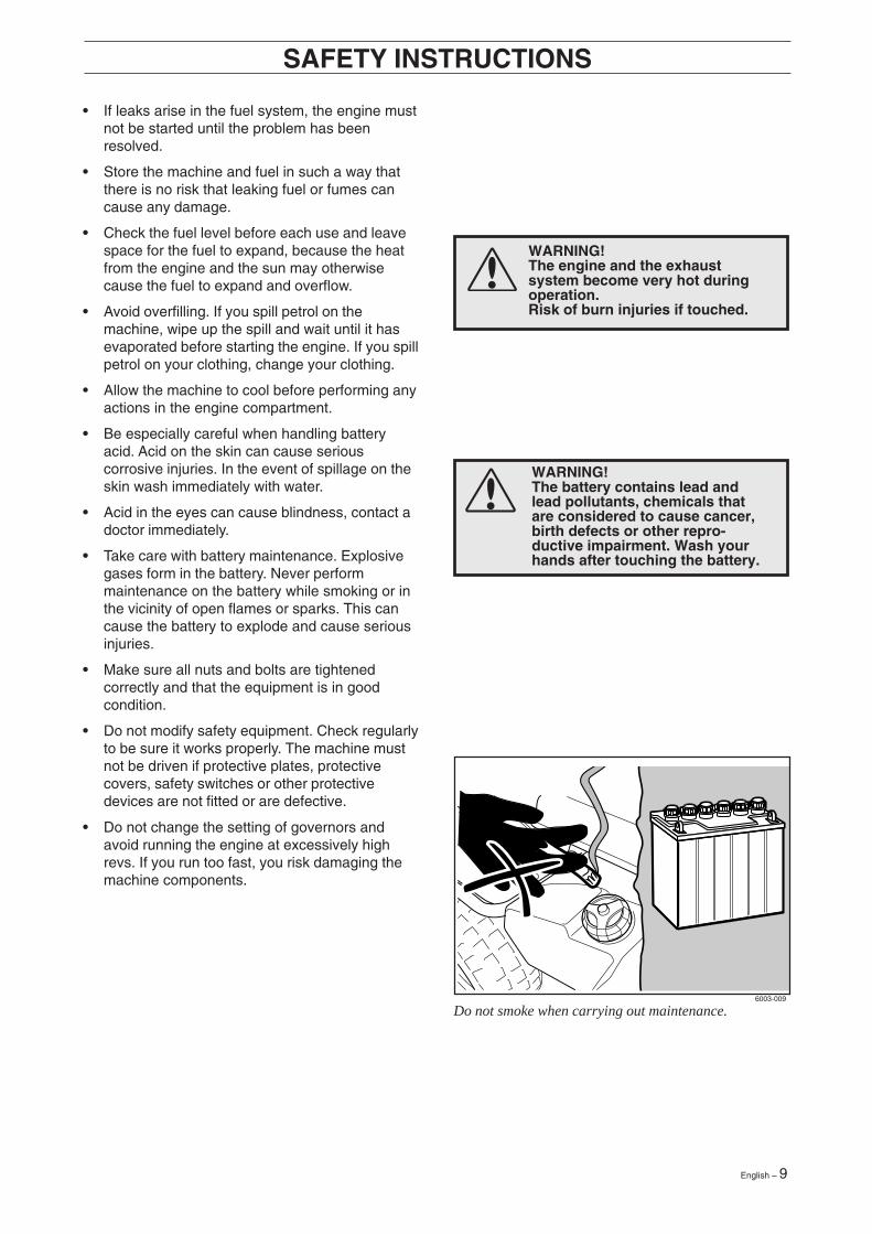
WARNING!The battery contains lead andlead pollutants, chemicals thatare considered to cause cancer,birth defects or other repro-ductive impairment. Wash yourhands after touching the battery.
6003-009
• If leaks arise in the fuel system, the engine mustnot be started until the problem has beenresolved.
• Store the machine and fuel in such a way thatthere is no risk that leaking fuel or fumes cancause any damage.
• Check the fuel level before each use and leavespace for the fuel to expand, because the heatfrom the engine and the sun may otherwisecause the fuel to expand and overflow.
• Avoid overfilling. If you spill petrol on themachine, wipe up the spill and wait until it hasevaporated before starting the engine. If you spillpetrol on your clothing, change your clothing.
• Allow the machine to cool before performing anyactions in the engine compartment.
• Be especially careful when handling batteryacid. Acid on the skin can cause seriouscorrosive injuries. In the event of spillage on theskin wash immediately with water.
• Acid in the eyes can cause blindness, contact adoctor immediately.
• Take care with battery maintenance. Explosivegases form in the battery. Never performmaintenance on the battery while smoking or inthe vicinity of open flames or sparks. This cancause the battery to explode and cause seriousinjuries.
• Make sure all nuts and bolts are tightenedcorrectly and that the equipment is in goodcondition.
• Do not modify safety equipment. Check regularlyto be sure it works properly. The machine mustnot be driven if protective plates, protectivecovers, safety switches or other protectivedevices are not fitted or are defective.
• Do not change the setting of governors andavoid running the engine at excessively highrevs. If you run too fast, you risk damaging themachine components.
SAFETY INSTRUCTIONS
Do not smoke when carrying out maintenance.
10 – English
8010-060
8010-061
SAFETY INSTRUCTIONS
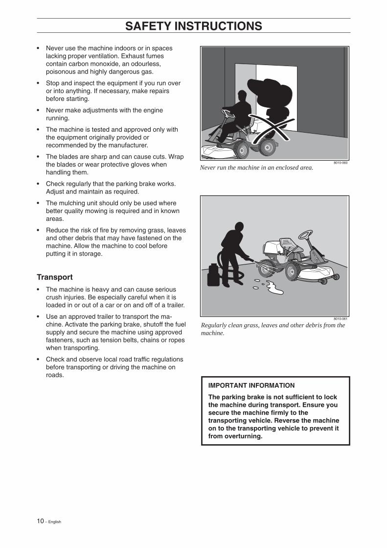
• Never use the machine indoors or in spaceslacking proper ventilation. Exhaust fumescontain carbon monoxide, an odourless,poisonous and highly dangerous gas.
• Stop and inspect the equipment if you run overor into anything. If necessary, make repairsbefore starting.
• Never make adjustments with the enginerunning.
• The machine is tested and approved only withthe equipment originally provided orrecommended by the manufacturer.
• The blades are sharp and can cause cuts. Wrapthe blades or wear protective gloves whenhandling them.
• Check regularly that the parking brake works.Adjust and maintain as required.
• The mulching unit should only be used wherebetter quality mowing is required and in knownareas.
• Reduce the risk of fire by removing grass, leavesand other debris that may have fastened on themachine. Allow the machine to cool beforeputting it in storage.
Transport
• The machine is heavy and can cause seriouscrush injuries. Be especially careful when it isloaded in or out of a car or on and off of a trailer.
• Use an approved trailer to transport the ma-chine. Activate the parking brake, shutoff the fuelsupply and secure the machine using approvedfasteners, such as tension belts, chains or ropeswhen transporting.
• Check and observe local road traffic regulationsbefore transporting or driving the machine onroads.
IMPORTANT INFORMATION
The parking brake is not sufficient to lockthe machine during transport. Ensure yousecure the machine firmly to thetransporting vehicle. Reverse the machineon to the transporting vehicle to prevent itfrom overturning.
Regularly clean grass, leaves and other debris from themachine.
Never run the machine in an enclosed area.

English – 11
Presentation
Congratulations on your choice of a top quality product which you will enjoy for many years.
These instructions describe the Rider 16. This rider mower is equipped with a 15.5 horsepower Briggs &Stratton engine.
The power transmission from the engine is handled by a hydrostatic gear box which enables stepless varia-tion of the speed with the foot pedals.
There is one pedal for driving forwards and one pedal for reversing.
PRESENTATION
Location of the controls
1. Ignition lock
2. Throttle/Choke lever
3. Adjustment of cutting height
4. Lifting lever, cutting unit
5. Speed limiter for reversing
6. Speed limiter for driving forwards
7. Parking brake
8. Lock button for parking brake
9. Knobs for adjusting seat
10. Fuel tank cap
11. Main lock (under seat)
12. Lever for disengagement of drive
12 – English
PRESENTATION
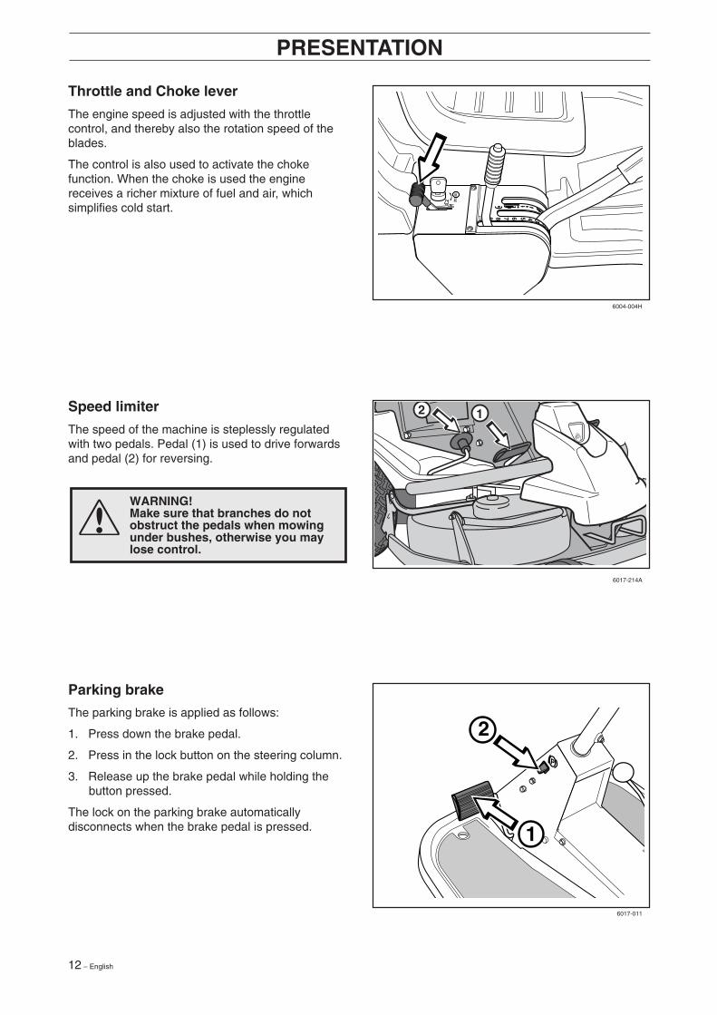
Throttle and Choke lever
The engine speed is adjusted with the throttlecontrol, and thereby also the rotation speed of theblades.
The control is also used to activate the chokefunction. When the choke is used the enginereceives a richer mixture of fuel and air, whichsimplifies cold start.
1
2
2 1
WARNING!Make sure that branches do notobstruct the pedals when mowingunder bushes, otherwise you maylose control.
Parking brake
The parking brake is applied as follows:
1. Press down the brake pedal.
2. Press in the lock button on the steering column.
3. Release up the brake pedal while holding thebutton pressed.
The lock on the parking brake automaticallydisconnects when the brake pedal is pressed.
Speed limiter
The speed of the machine is steplessly regulatedwith two pedals. Pedal (1) is used to drive forwardsand pedal (2) for reversing.
6004-004H
6017-214A
6017-011

English – 13
PRESENTATION
Cutting unit
The Rider 16 can be fitted with four different cuttingunits.
Rear ejector - 970 mmSide ejector - 970 mmBioClip - 900 mm, 1030 mmCombi - 1120 mm Combi
See ”Maintenance \ Checking the Blades” foridentification of the cutting unit.
Lifting of the cutting unit (transport position)
Lowering of the cutting unit (cutting position)
Lift lever for cutting unit
The lift lever is used to set the cutting unit in trans-port or cutting position.
If the lever is pulled back the unit will lift up and theblades will automatically stop rotating (transportposition).
If the lock button is pressed and the lever is movedforward the unit will be lowered and the blades willautomatically start rotating (cutting position).
The lever can also be used to temporarily regulatethe cutting height, e.g. for a small mound in thelawn.
6017-214
6004-011H
6004-012H
14 – English
PRESENTATION
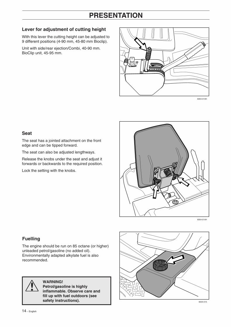
Fuelling
The engine should be run on 85 octane (or higher)unleaded petrol/gasoline (no added oil).Environmentally adapted alkylate fuel is alsorecommended.
Seat
The seat has a jointed attachment on the frontedge and can be tipped forward.
The seat can also be adjusted lengthways.
Release the knobs under the seat and adjust itforwards or backwards to the required position.
Lock the setting with the knobs.
Lever for adjustment of cutting height
With this lever the cutting height can be adjusted to9 different positions (4-90 mm, 45-80 mm Bioclip).
Unit with side/rear ejection/Combi, 40-90 mm.BioClip unit, 45-95 mm.
WARNING!Petrol/gasoline is highlyinflammable. Observe care andfill up with fuel outdoors (seesafety instructions).
6004-013H
6004-014H
6004-015

English – 15
• Read the safety instructions and information onthe location and function of the controls beforestarting (see pages 5-14).
• Conduct daily maintenance before starting (seemaintenance schedule on page 20).
Adjust the seat to the required position.
Starting the engine
1. Lift up the cutting unit by pulling the leverbackwards to locked position (transport posi-tion).
DRIVING
2. Apply the parking brake. This is done as follows:
• Press down the brake pedal (1).
• Press in the lock button on the steeringcolumn (2).
• Release the brake pedal while the button isheld pressed.
The parking brake lock disconnects automatically when the brake pedal is pressed down.
Cold engine:3. Push the throttle control to position 3 (choke
position). In this position the engine receives aricher mixture so that the engine starts moreeasily.
1
2
12
3
6007-001H
6017-011
6007-004H
16 – English
DRIVING
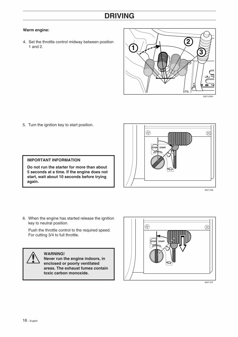
Warm engine:
4. Set the throttle control midway between position1 and 2.
WARNING!Never run the engine indoors, inenclosed or poorly ventilatedareas. The exhaust fumes containtoxic carbon monoxide.
6. When the engine has started release the ignitionkey to neutral position.
Push the throttle control to the required speed.For cutting 3/4 to full throttle.
IMPORTANT INFORMATION
Do not run the starter for more than about5 seconds at a time. If the engine does notstart, wait about 10 seconds before tryingagain.
5. Turn the ignition key to start position.
12
3
STOP START
STOP START
6007-005H
6007-006
6007-007
English – 17
DRIVING
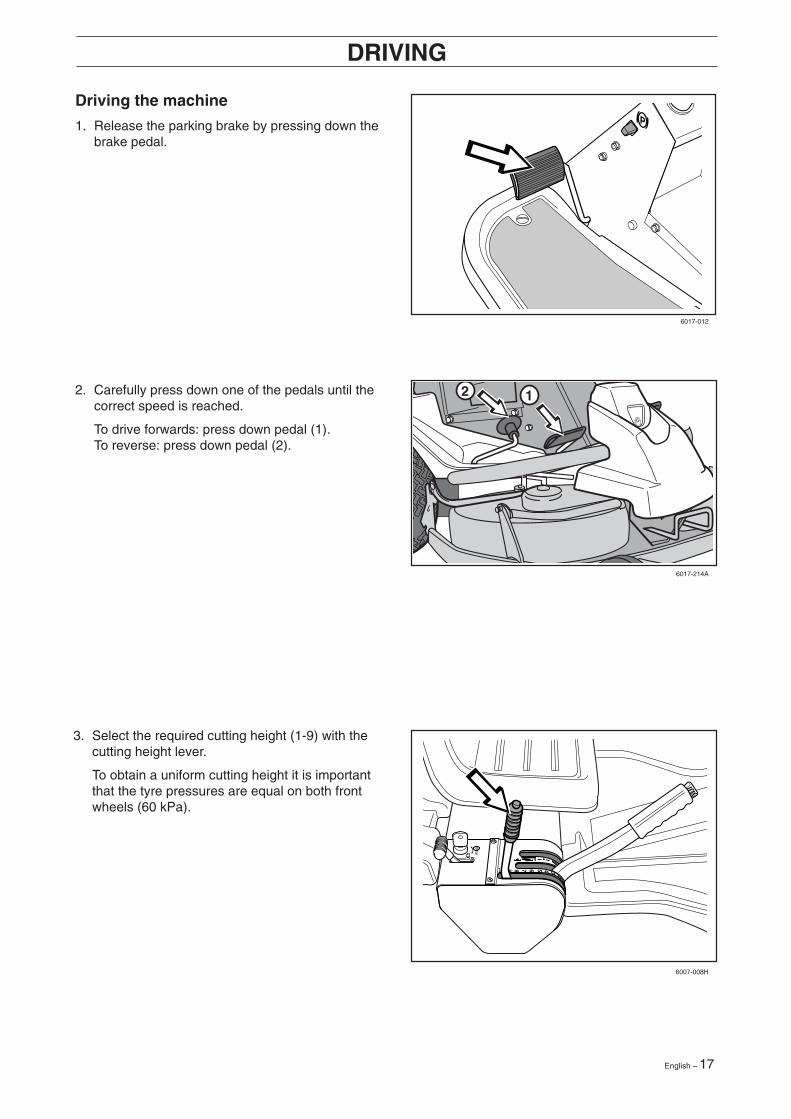
Driving the machine
1. Release the parking brake by pressing down thebrake pedal.
3. Select the required cutting height (1-9) with thecutting height lever.
To obtain a uniform cutting height it is importantthat the tyre pressures are equal on both frontwheels (60 kPa).
2 12. Carefully press down one of the pedals until thecorrect speed is reached.
To drive forwards: press down pedal (1).To reverse: press down pedal (2).
6017-012
6017-214A
6007-008H

18 – English
Mowing pattern
DRIVING
4. Push in the lock button on the lift lever andlower down the cutting unit.
WARNING!Clear the lawn from stones andother object which can be thrownout by the blades.
Cutting tips
• Localise and mark stones and other fixedobjects to avoid collision.
• Start with a high cutting height and reduce downuntil the required cutting result are obtained.
• The cutting results are best with a high enginespeed (fast rotating blades) and low drivingspeed (slow moving machine). If the grass is nottoo high and thick, the driving speed can beincreased without noticeably depreciating themowing result.
• The best lawns are achieved if the grass is cutoften. Mowing becomes more uniform and thegrass cuttings become more evenly distributedover the surface. The total time consumption isnot greater since it is possible to select a higherdriving speed without inferior mowing results.
• Avoid mowing a wet lawn. The mowing resultsare inferior since the wheels sink down into thesoft lawn.
• Wash down the underside of the cutting unit withwater after use. Do not use a high pressure jet.Put the cutting unit in the service position whiledoing this.
• If you use the BioClip unit it is important to mowthe grass regularly.
IMPORTANT INFORMATION
The service-life of the drive beltsincreases considerably if the engine isrun at low speed when engaging theblades. For this reason do not increasethe throttle until the cutting unit has beenlowered to the cutting position.
6007-212
6007-009H
English – 19
DRIVING
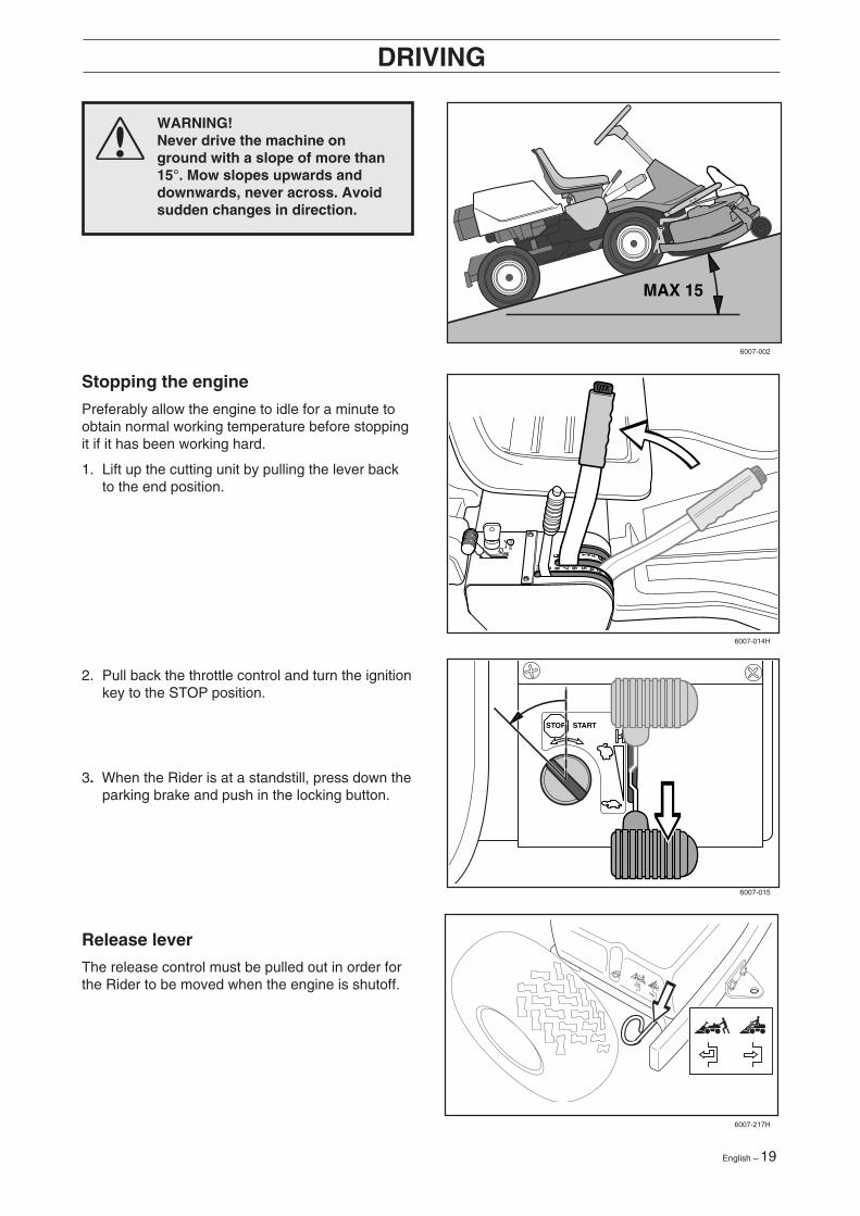
Stopping the engine
Preferably allow the engine to idle for a minute toobtain normal working temperature before stoppingit if it has been working hard.
1. Lift up the cutting unit by pulling the lever backto the end position.
STOP START
MAX 15
WARNING!Never drive the machine onground with a slope of more than15°. Mow slopes upwards anddownwards, never across. Avoidsudden changes in direction.
Release lever
The release control must be pulled out in order forthe Rider to be moved when the engine is shutoff.
2. Pull back the throttle control and turn the ignitionkey to the STOP position.
3. When the Rider is at a standstill, press down theparking brake and push in the locking button.
6007-002
6007-014H
6007-015
6007-217H

20 – English
50 100
MAINTENANCE
25
WARNING!
No service procedures must be conducted on the engine or cutting unit unless:
• The engine is switched off.
• The ignition key is removed.
• The ignition cable is removed from the plug.
• The parking brake is applied.
• The cutting unit is disengaged.
Maintenance schedule
The following is a list of the maintenance which should be conducted on the machine. For the items whichare not described in these instructions go to an authorised service workshop.
Dailymaintenancebefore start
● = Described in these instructions.❍ = Not described in these instructions.
Maintenance Page
Maintenance intervalin hours
1) First change after 5 hours. 2) During dusty conditions cleaning and replacement should be more frequent. 3) For daily use of themachine lubrication should be conducted twice a week. 4) Conducted by authorised service workshop.
Check the engine’s oil level 38 ●
Check the engine’s cooling air inlet 27 ●
Check the fuel pump’s air filter 25 ●
Check the steering wires 22 ●
Check the battery 25 ●
Check the safety system 26 ●
Check screws and nuts – ❍
Check for fuel and oil leakage – ❍
Change the engine oil 1) 38 ●
Clean the air filter’s pre-filter (foam plastic) 2) 24 ●
Check the cutting unit 29 ●
Check the tyre pressures (60 kPa) 27 ●
Lubricating the belt adjuster 3) 39 ●
Lubricate joints and shafts 3) 39 ●
Check the V-belts – ❍
Check the hydrostat’s cooling fins – ❍
Check the transmission’s oil level 39 ●
Adjust the brakes 22 ●
Check and adjust the throttle wire 23 ●
Clean the engine’s and hydrostat’s cooling flanges 2,4) – ❍
Replace the air filter’s pre-filter and paper filter 2) 24 ●
Replace the fuel filter 23 ●
Replace the plug 25 ●
English – 21
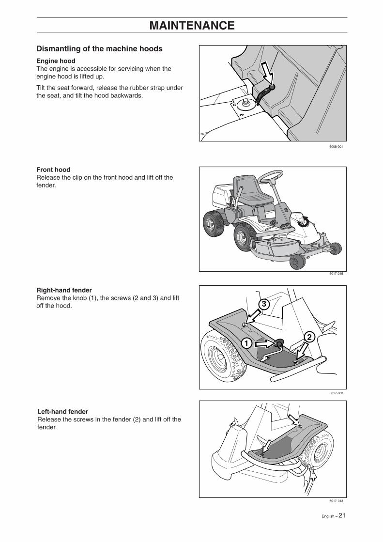
Dismantling of the machine hoods
Engine hoodThe engine is accessible for servicing when theengine hood is lifted up.
Tilt the seat forward, release the rubber strap underthe seat, and tilt the hood backwards.
MAINTENANCE
Left-hand fenderRelease the screws in the fender (2) and lift off thefender.
Right-hand fenderRemove the knob (1), the screws (2 and 3) and liftoff the hood.
Front hoodRelease the clip on the front hood and lift off thefender.
211
3
1
6008-001
6017-215
6017-003
6017-013
22 – English
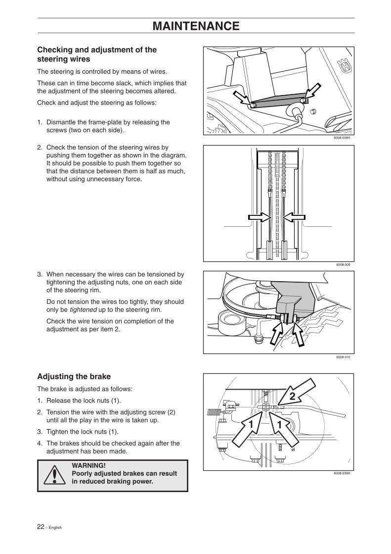
Checking and adjustment of thesteering wires
The steering is controlled by means of wires.
These can in time become slack, which implies thatthe adjustment of the steering becomes altered.
Check and adjust the steering as follows:
1. Dismantle the frame-plate by releasing thescrews (two on each side).
MAINTENANCE
Adjusting the brake
The brake is adjusted as follows:
1. Release the lock nuts (1).
2. Tension the wire with the adjusting screw (2)until all the play in the wire is taken up.
3. Tighten the lock nuts (1).
4. The brakes should be checked again after theadjustment has been made.
WARNING!Poorly adjusted brakes can resultin reduced braking power.
3. When necessary the wires can be tensioned bytightening the adjusting nuts, one on each sideof the steering rim.
Do not tension the wires too tightly, they shouldonly be tightened up to the steering rim.
Check the wire tension on completion of theadjustment as per item 2.
2. Check the tension of the steering wires bypushing them together as shown in the diagram.It should be possible to push them together sothat the distance between them is half as much,without using unnecessary force.
R I D E R 8 5 0
R I D E R 8 5 0
1 1
2
6008-008H
6008-009
6008-010
6008-239H
English – 23
MAINTENANCE
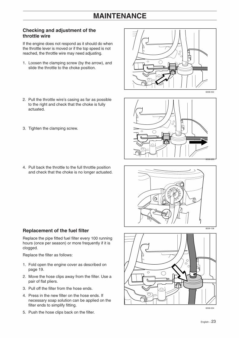
Checking and adjustment of thethrottle wire
If the engine does not respond as it should do whenthe throttle lever is moved or if the top speed is notreached, the throttle wire may need adjusting.
1. Loosen the clamping screw (by the arrow), andslide the throttle to the choke position.
Replacement of the fuel filter
Replace the pipe fitted fuel filter every 100 runninghours (once per season) or more frequently if it isclogged.
Replace the filter as follows:
1. Fold open the engine cover as described onpage 19.
2. Move the hose clips away from the filter. Use apair of flat pliers.
3. Pull off the filter from the hose ends.
4. Press in the new filter on the hose ends. Ifnecessary soap solution can be applied on thefilter ends to simplify fitting.
5. Push the hose clips back on the filter.
2. Pull the throttle wire’s casing as far as possibleto the right and check that the choke is fullyactuated.
3. Tighten the clamping screw.
4. Pull back the throttle to the full throttle positionand check that the choke is no longer actuated.
6008-032
6008-033
8009-108
6008-034

24 – English
Replacing the air filter
If the engine seems to lack power or goesirregularly the reason may be that the air filter isclogged.
It is therefore important to replace the air filter atregular intervals (see ”Maintenance schedule” onpage 20 for correct service interval).
1. Fold open the engine cover.
2. Remove the air filter housing’s plastic cover byreleasing the wing-nut.
MAINTENANCE
5. Fit the air filter as follows:
Push the pre-filter over the paper filter.
Fit the paper filter with pre-filter in the air filterhousing and tighten the wing-nut.
Replace the plastic cover oven the air filterhousing and tighten the wing-nut.
IMPORTANT INFORMATION
Do not use compressed air to clean thepaper filter.
4. Pull off the foam plastic pre-filter from the paperfilter and wash clean in mild detergent.
Squeeze it dry in a clean cloth.
Drench it with new engine oil. Wrap the filter inan absorbent cloth and squeeze out excess oil.
Replace the paper filter if it is clogged with dirt.
3. Remove the wing-nut on the air filter and lift offthe paper filter with pre-filter.
6008-014
6008-015
6008-016
6008-017
English – 25
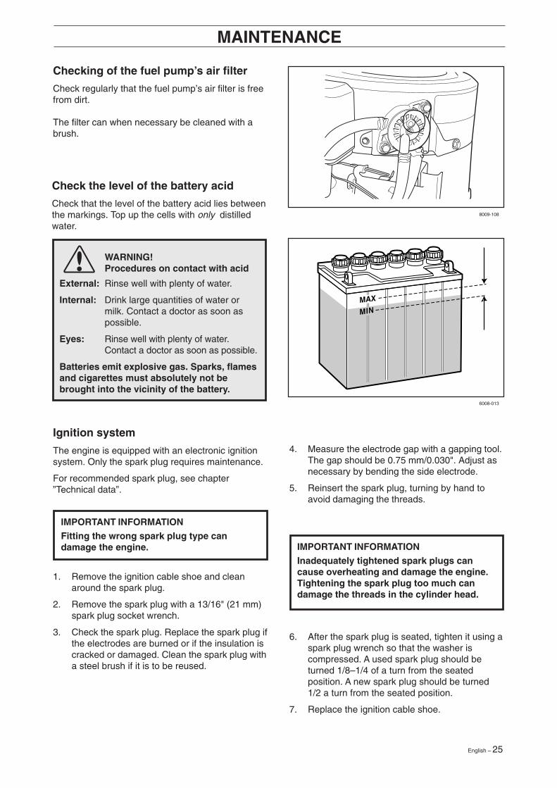
WARNING!Procedures on contact with acid
External: Rinse well with plenty of water.
Internal: Drink large quantities of water ormilk. Contact a doctor as soon aspossible.
Eyes: Rinse well with plenty of water.Contact a doctor as soon as possible.
Batteries emit explosive gas. Sparks, flamesand cigarettes must absolutely not bebrought into the vicinity of the battery.
Check the level of the battery acid
Check that the level of the battery acid lies betweenthe markings. Top up the cells with only distilledwater.
Checking of the fuel pump’s air filter
Check regularly that the fuel pump’s air filter is freefrom dirt.
The filter can when necessary be cleaned with abrush.
MAINTENANCE
8009-108
6008-013
Ignition system
The engine is equipped with an electronic ignitionsystem. Only the spark plug requires maintenance.
For recommended spark plug, see chapter”Technical data”.
IMPORTANT INFORMATION
Fitting the wrong spark plug type candamage the engine.
1. Remove the ignition cable shoe and cleanaround the spark plug.
2. Remove the spark plug with a 13/16" (21 mm)spark plug socket wrench.
3. Check the spark plug. Replace the spark plug ifthe electrodes are burned or if the insulation iscracked or damaged. Clean the spark plug witha steel brush if it is to be reused.
IMPORTANT INFORMATION
Inadequately tightened spark plugs cancause overheating and damage the engine.Tightening the spark plug too much candamage the threads in the cylinder head.
6. After the spark plug is seated, tighten it using aspark plug wrench so that the washer iscompressed. A used spark plug should beturned 1/8–1/4 of a turn from the seatedposition. A new spark plug should be turned1/2 a turn from the seated position.
7. Replace the ignition cable shoe.
4. Measure the electrode gap with a gapping tool.The gap should be 0.75 mm/0.030". Adjust asnecessary by bending the side electrode.
5. Reinsert the spark plug, turning by hand toavoid damaging the threads.
26 – English
MAINTENANCE
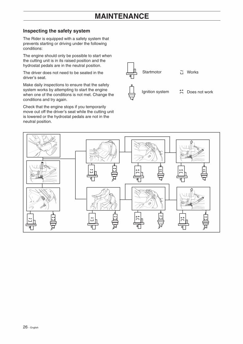
Inspecting the safety system
The Rider is equipped with a safety system thatprevents starting or driving under the followingconditions:
The engine should only be possible to start whenthe cutting unit is in its raised position and thehydrostat pedals are in the neutral position.
The driver does not need to be seated in thedriver’s seat.
Make daily inspections to ensure that the safetysystem works by attempting to start the enginewhen one of the conditions is not met. Change theconditions and try again.
Check that the engine stops if you temporarilymove out off the driver’s seat while the cutting unitis lowered or the hydrostat pedals are not in theneutral position.
Startmotor
Ignition system
Works
Does not work
English – 27
MAINTENANCE
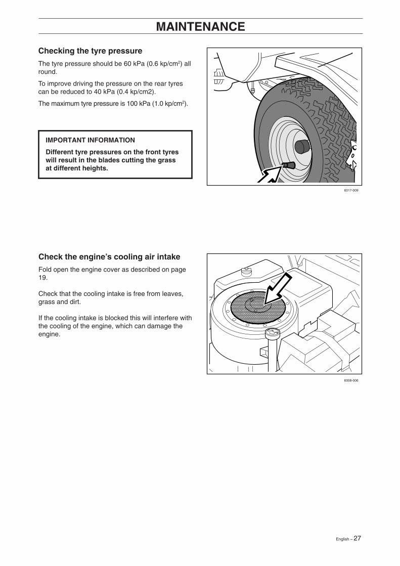
Check the engine’s cooling air intake
Fold open the engine cover as described on page19.
Check that the cooling intake is free from leaves,grass and dirt.
If the cooling intake is blocked this will interfere withthe cooling of the engine, which can damage theengine.
Checking the tyre pressure
The tyre pressure should be 60 kPa (0.6 kp/cm2) allround.
To improve driving the pressure on the rear tyrescan be reduced to 40 kPa (0.4 kp/cm2).
The maximum tyre pressure is 100 kPa (1.0 kp/cm2).
IMPORTANT INFORMATION
Different tyre pressures on the front tyreswill result in the blades cutting the grassat different heights.
6017-009
6008-006
28 – English
MAINTENANCE
12
3
1
2
8 9
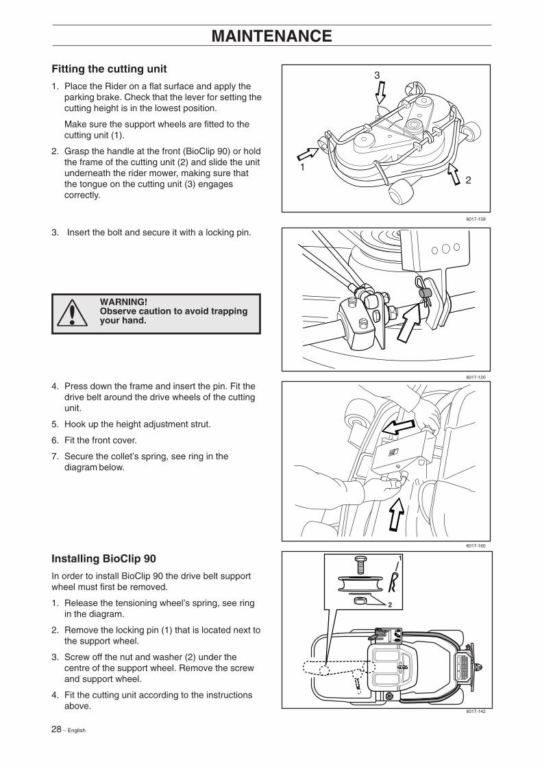
Fitting the cutting unit
1. Place the Rider on a flat surface and apply theparking brake. Check that the lever for setting thecutting height is in the lowest position.
Make sure the support wheels are fitted to thecutting unit (1).
2. Grasp the handle at the front (BioClip 90) or holdthe frame of the cutting unit (2) and slide the unitunderneath the rider mower, making sure thatthe tongue on the cutting unit (3) engagescorrectly.
3. Insert the bolt and secure it with a locking pin.
4. Press down the frame and insert the pin. Fit thedrive belt around the drive wheels of the cuttingunit.
5. Hook up the height adjustment strut.
6. Fit the front cover.
7. Secure the collet’s spring, see ring in thediagram below.
Installing BioClip 90
In order to install BioClip 90 the drive belt supportwheel must first be removed.
1. Release the tensioning wheel’s spring, see ringin the diagram.
2. Remove the locking pin (1) that is located next tothe support wheel.
3. Screw off the nut and washer (2) under thecentre of the support wheel. Remove the screwand support wheel.
4. Fit the cutting unit according to the instructionsabove.
6017-159
6017-120
6017-160
6017-142
WARNING!Observe caution to avoid trappingyour hand.
English – 29
MAINTENANCE
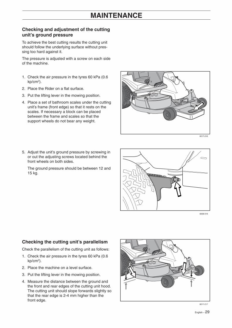
Checking and adjustment of the cuttingunit’s ground pressure
To achieve the best cutting results the cutting unitshould follow the underlying surface without pres-sing too hard against it.
The pressure is adjusted with a screw on each sideof the machine.
1. Check the air pressure in the tyres 60 kPa (0.6kp/cm2).
2. Place the Rider on a flat surface.
3. Put the lifting lever in the mowing position.
4. Place a set of bathroom scales under the cuttingunit’s frame (front edge) so that it rests on thescales. If necessary a block can be placedbetween the frame and scales so that thesupport wheels do not bear any weight.
Checking the cutting unit’s parallelism
Check the parallelism of the cutting unit as follows:
1. Check the air pressure in the tyres 60 kPa (0.6kp/cm2).
2. Place the machine on a level surface.
3. Put the lifting lever in the mowing position.
4. Measure the distance between the ground andthe front and rear edges of the cutting unit hood.The cutting unit should slope forwards slightly sothat the rear edge is 2-4 mm higher than thefront edge.
5. Adjust the unit’s ground pressure by screwing inor out the adjusting screws located behind thefront wheels on both sides.
The ground pressure should be between 12 and15 kg.
6017-216
6008-019
6017-217
30 – English
MAINTENANCE
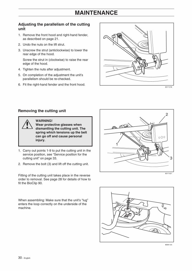
WARNING!Wear protective glasses whendismantling the cutting unit. Thespring which tensions up the beltcan go off and cause personalinjury.
Adjusting the parallelism of the cuttingunit
1. Remove the front hood and right-hand fender,as described on page 21.
2. Undo the nuts on the lift strut.
3. Unscrew the strut (anticlockwise) to lower therear edge of the hood.
Screw the strut in (clockwise) to raise the rearedge of the hood.
4. Tighten the nuts after adjustment.
5. On completion of the adjustment the unit’sparallelism should be re-checked.
6. Fit the right-hand fender and the front hood.
Removing the cutting unit
1. Carry out points 1-9 to put the cutting unit in theservice position, see “Service position for thecutting unit” on page 33.
2. Remove the bolt (3) and lift off the cutting unit.
Fitting of the cutting unit takes place in the reverseorder to removal. See page 28 for details of how tofit the BioClip 90.
When assembling: Make sure that the unit’s “lug”enters the loop correctly on the underside of themachine.
2
3
1
6017-018
6017-021
8009-123
English – 31
MAINTENANCE
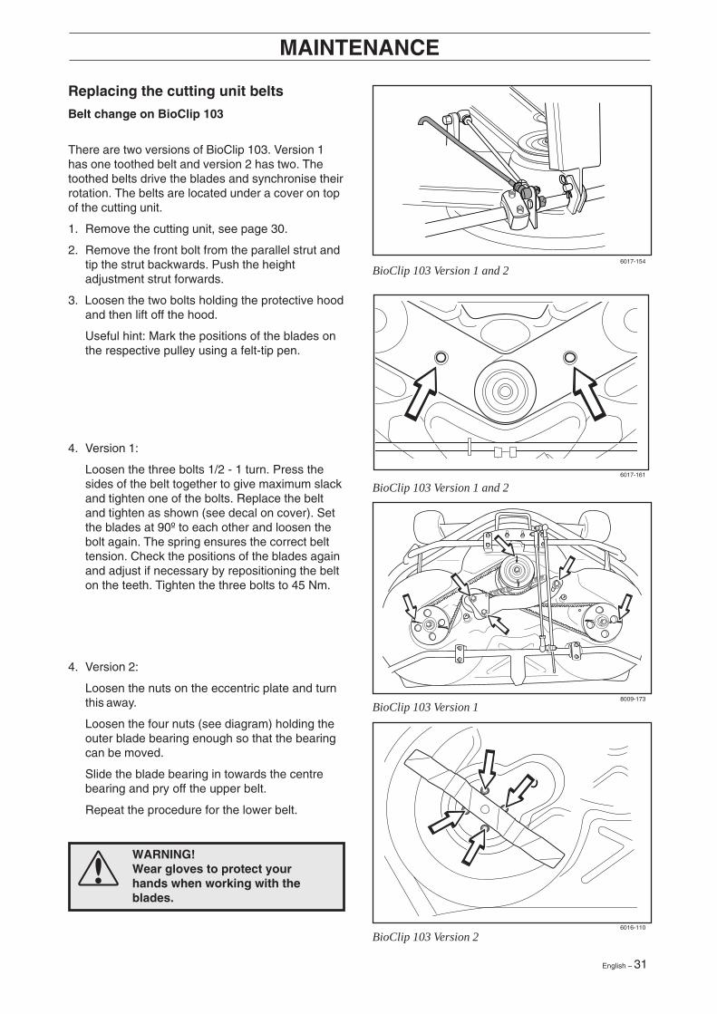
Replacing the cutting unit belts
Belt change on BioClip 103
There are two versions of BioClip 103. Version 1has one toothed belt and version 2 has two. Thetoothed belts drive the blades and synchronise theirrotation. The belts are located under a cover on topof the cutting unit.
1. Remove the cutting unit, see page 30.
2. Remove the front bolt from the parallel strut andtip the strut backwards. Push the heightadjustment strut forwards.
3. Loosen the two bolts holding the protective hoodand then lift off the hood.
Useful hint: Mark the positions of the blades onthe respective pulley using a felt-tip pen.
WARNING!Wear gloves to protect yourhands when working with theblades.
6017-154
6016-110
8009-173
6017-161
BioClip 103 Version 1
BioClip 103 Version 2
BioClip 103 Version 1 and 2
BioClip 103 Version 1 and 2
4. Version 2:
Loosen the nuts on the eccentric plate and turnthis away.
Loosen the four nuts (see diagram) holding theouter blade bearing enough so that the bearingcan be moved.
Slide the blade bearing in towards the centrebearing and pry off the upper belt.
Repeat the procedure for the lower belt.
4. Version 1:
Loosen the three bolts 1/2 - 1 turn. Press thesides of the belt together to give maximum slackand tighten one of the bolts. Replace the beltand tighten as shown (see decal on cover). Setthe blades at 90º to each other and loosen thebolt again. The spring ensures the correct belttension. Check the positions of the blades againand adjust if necessary by repositioning the belton the teeth. Tighten the three bolts to 45 Nm.
32 – English
MAINTENANCE
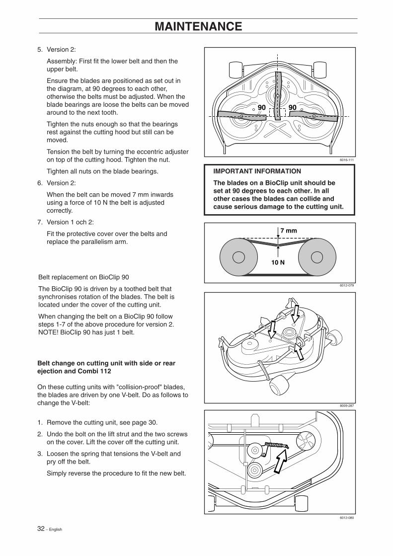
IMPORTANT INFORMATION
The blades on a BioClip unit should beset at 90 degrees to each other. In allother cases the blades can collide andcause serious damage to the cutting unit.
5. Version 2:
Assembly: First fit the lower belt and then theupper belt.
Ensure the blades are positioned as set out inthe diagram, at 90 degrees to each other,otherwise the belts must be adjusted. When theblade bearings are loose the belts can be movedaround to the next tooth.
Tighten the nuts enough so that the bearingsrest against the cutting hood but still can bemoved.
Tension the belt by turning the eccentric adjusteron top of the cutting hood. Tighten the nut.
Tighten all nuts on the blade bearings.
6. Version 2:
When the belt can be moved 7 mm inwardsusing a force of 10 N the belt is adjustedcorrectly.
7. Version 1 och 2:
Fit the protective cover over the belts andreplace the parallelism arm.
Belt replacement on BioClip 90
The BioClip 90 is driven by a toothed belt thatsynchronises rotation of the blades. The belt islocated under the cover of the cutting unit.
When changing the belt on a BioClip 90 followsteps 1-7 of the above procedure for version 2.NOTE! BioClip 90 has just 1 belt.
Belt change on cutting unit with side or rearejection and Combi 112
On these cutting units with "collision-proof" blades,the blades are driven by one V-belt. Do as follows tochange the V-belt:
1. Remove the cutting unit, see page 30.
2. Undo the bolt on the lift strut and the two screwson the cover. Lift the cover off the cutting unit.
3. Loosen the spring that tensions the V-belt andpry off the belt.
Simply reverse the procedure to fit the new belt.
6016-111
6012-079
8009-287
6012-080
English – 33
MAINTENANCE
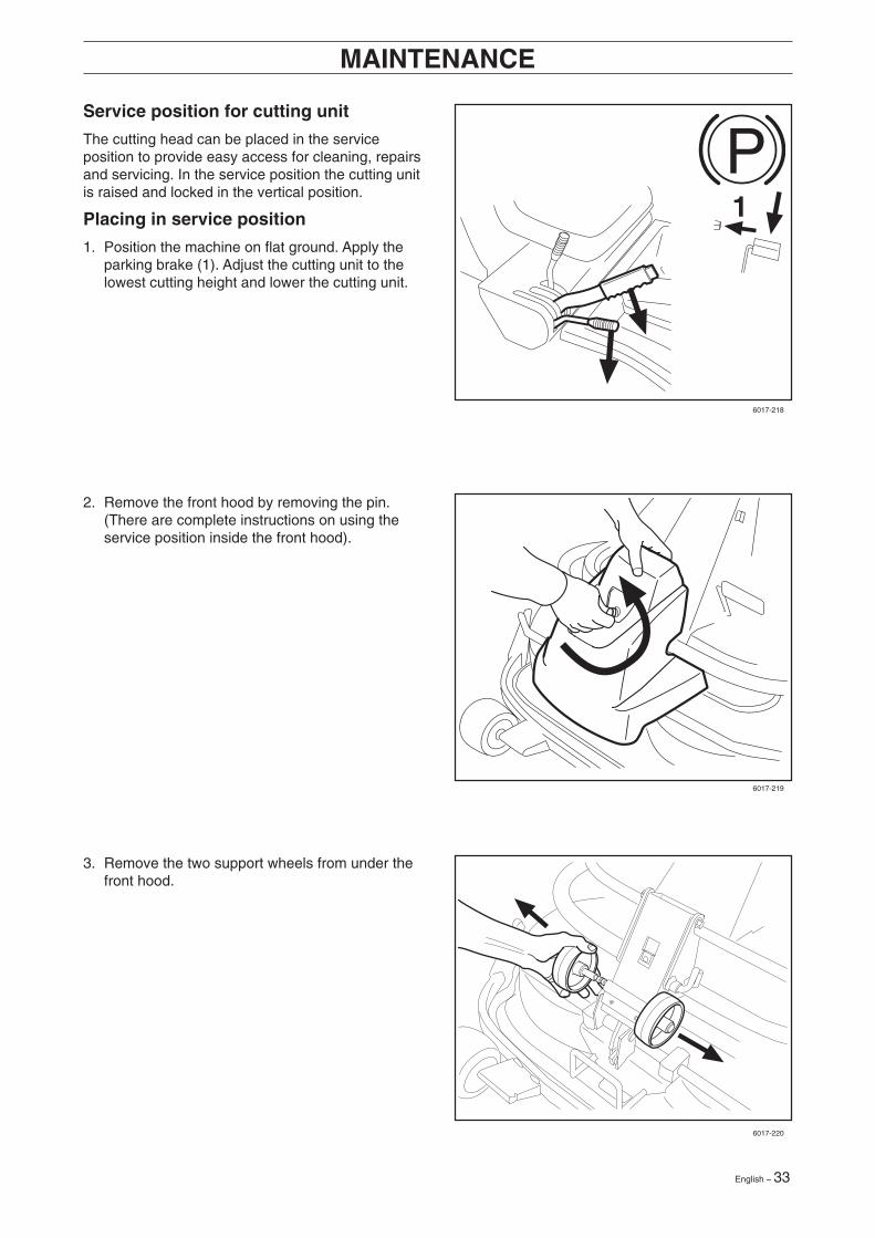
Service position for cutting unit
The cutting head can be placed in the serviceposition to provide easy access for cleaning, repairsand servicing. In the service position the cutting unitis raised and locked in the vertical position.
Placing in service position
1. Position the machine on flat ground. Apply theparking brake (1). Adjust the cutting unit to thelowest cutting height and lower the cutting unit.
P1
2. Remove the front hood by removing the pin.(There are complete instructions on using theservice position inside the front hood).
3. Remove the two support wheels from under thefront hood.
6017-218
6017-219
6017-220
34 – English
MAINTENANCE
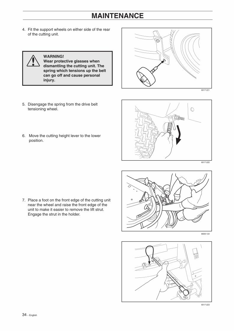
4. Fit the support wheels on either side of the rearof the cutting unit.
5. Disengage the spring from the drive belttensioning wheel.
7. Place a foot on the front edge of the cutting unitnear the wheel and raise the front edge of theunit to make it easier to remove the lift strut.Engage the strut in the holder.
WARNING!Wear protective glasses whendismantling the cutting unit. Thespring which tensions up the beltcan go off and cause personalinjury.
6. Move the cutting height lever to the lowerposition.
6017-221
6017-222
8009-122
6017-223
English – 35
MAINTENANCE
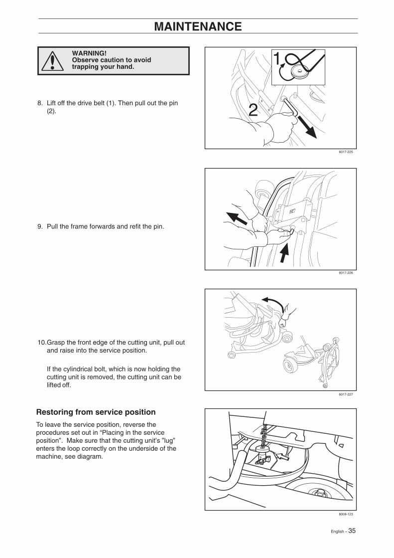
Restoring from service position
To leave the service position, reverse theprocedures set out in “Placing in the serviceposition”. Make sure that the cutting unit’s ”lug”enters the loop correctly on the underside of themachine, see diagram.
2
1
8. Lift off the drive belt (1). Then pull out the pin(2).
9. Pull the frame forwards and refit the pin.
10.Grasp the front edge of the cutting unit, pull outand raise into the service position.
If the cylindrical bolt, which is now holding thecutting unit is removed, the cutting unit can belifted off.
6017-225
6017-226
6017-227
8009-123
WARNING!Observe caution to avoidtrapping your hand.
36 – English
MAINTENANCE
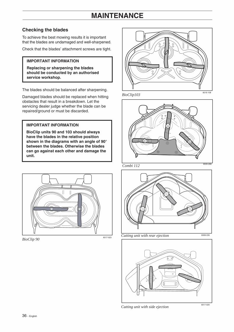
Checking the blades
To achieve the best mowing results it is importantthat the blades are undamaged and well-sharpened.
Check that the blades’ attachment screws are tight.
IMPORTANT INFORMATION
Replacing or sharpening the bladesshould be conducted by an authorisedservice workshop.
IMPORTANT INFORMATION
BioClip units 90 and 103 should alwayshave the blades in the relative positionshown in the diagrams with an angle of 90°between the blades. Otherwise the bladescan go against each other and damage theunit.
BioClip103
Cutting unit with side ejection
Cutting unit with rear ejection
The blades should be balanced after sharpening.
Damaged blades should be replaced when hittingobstacles that result in a breakdown. Let theservicing dealer judge whether the blade can berepaired/ground or must be discarded.
6016-108
8009-288Combi 112
6008-226
6017-020
6017-023BioClip 90
English – 37
MAINTENANCE
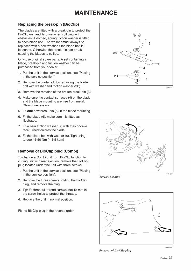
Replacing the break-pin (BioClip)
The blades are fitted with a break-pin to protect theBioClip unit and its drive when colliding withobstacles. A domed, spring friction washer is fittedto each blade bolt. The washer must always bereplaced with a new washer if the blade bolt isloosened. Otherwise the break-pin can breakcausing the blades to collide.
Only use original spare parts. A set containing ablade, break-pin and friction washer can bepurchased from your dealer.
1. Put the unit in the service position, see ”Placingin the service position”.
2. Remove the blade (2A) by removing the bladebolt with washer and friction washer (2B).
3. Remove the remains of the broken break-pin (3).
4. Make sure the contact surfaces (4) on the bladeand the blade mounting are free from metal.Clean if necessary.
5. Fit one new break-pin (5) in the blade mounting.
6. Fit the blade (6), make sure it is fitted asillustrated.
7. Fit a new friction washer (7) with the concaveface turned towards the blade.
8. Fit the blade bolt with washer (8). Tighteningtorque 45-50 Nm (4,5-5 kpm)
Removal of BioClip plug (Combi)
To change a Combi unit from BioClip function tocutting unit with rear ejection, remove the BioClipplug located under the unit with three screws.
1. Put the unit in the service position, see "Placingin the service position".
2. Remove the three screws holding the BioClipplug, and remove the plug.
3. Tip: Fit three full-thread screws M8x15 mm inthe screw holes to protect the threads.
4. Replace the unit in normal position.
Fit the BioClip plug in the reverse order.
2B
3
4
4
6
2A
7
8
5
8009-137
8009-289
6017-227
Removal of BioClip plug
Service position
38 – English
LUBRICATION
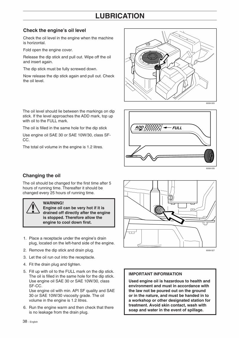
Changing the oil
The oil should be changed for the first time after 5hours of running time. Thereafter it should bechanged every 25 hours of running time.
WARNING!Engine oil can be very hot if it isdrained off directly after the engineis stopped. Therefore allow theengine to cool down first.
IMPORTANT INFORMATION
Used engine oil is hazardous to health andenvironment and must in accordance withthe law not be poured out on the groundor in the nature, and must be handed in toa workshop or other designated station fortreatment. Avoid skin contact, wash withsoap and water in the event of spillage.
Check the engine’s oil level
Check the oil level in the engine when the machineis horizontal.
Fold open the engine cover.
Release the dip stick and pull out. Wipe off the oiland insert again.
The dip stick must be fully screwed down.
Now release the dip stick again and pull out. Checkthe oil level.
The oil level should lie between the markings on dipstick. If the level approaches the ADD mark, top upwith oil to the FULL mark.
The oil is filled in the same hole for the dip stick
Use engine oil SAE 30 or SAE 10W/30, class SF-CC.
The total oil volume in the engine is 1.2 litres.
ADD FULL
ADD FULL
6008-005
6008-035
6008-027
1. Place a receptacle under the engine’s drainplug, located on the left-hand side of the engine.
2. Remove the dip stick and drain plug.
3. Let the oil run out into the receptacle.
4. Fit the drain plug and tighten.
5. Fill up with oil to the FULL mark on the dip stick.The oil is filled in the same hole for the dip stick.Use engine oil SAE 30 or SAE 10W/30, classSF-CC.Use engine oil with min. API SF quality and SAE30 or SAE 10W/30 viscosity grade. The oilvolume in the engine is 1.2 litres.
6. Run the engine warm and then check that thereis no leakage from the drain plug.
English – 39
LUBRICATION
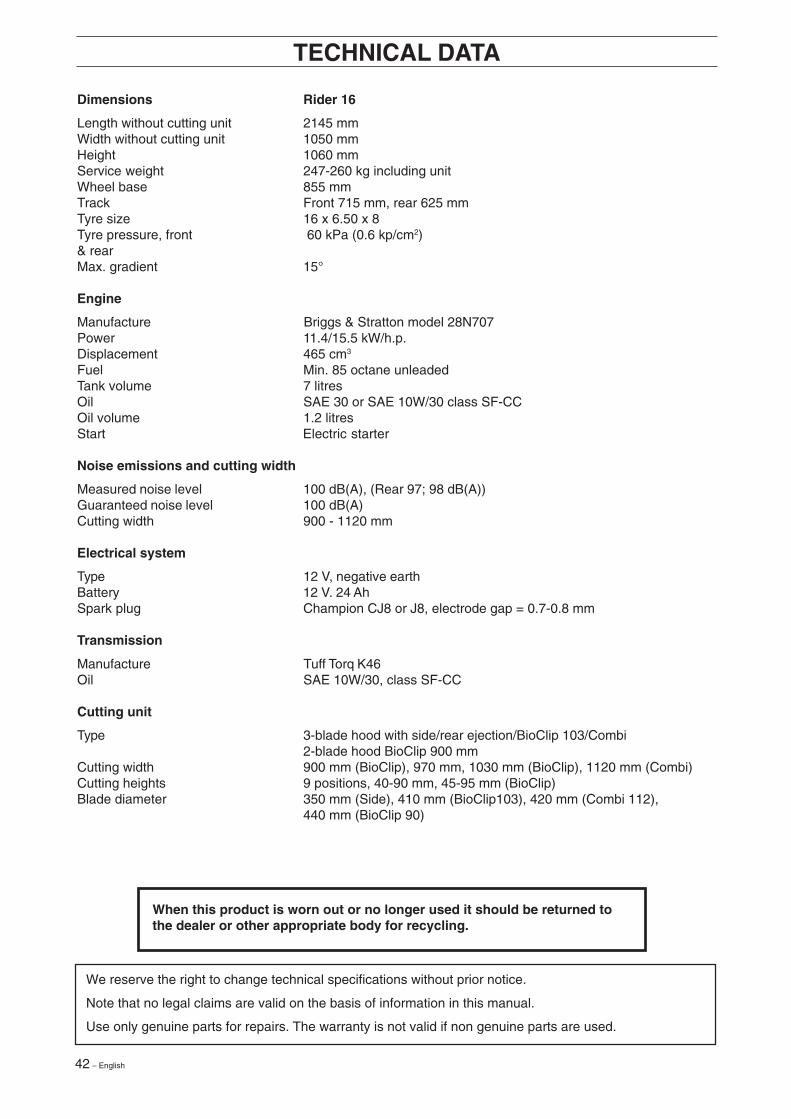
Lubricating the belt adjuster
The belt adjuster should be lubricated regularlyusing good quality molybdenum disulphidegrease*.1 nipple from the right-hand side under the engine’slower belt pulley, until grease is forced out.
With daily use lubrication should be conductedtwice a week.
General lubrication
All joints and bearings are lubricated onmanufacture with molybdenum sulphide grease.Re-grease with same type of grease*. Lubricate thesteering and control wires with engine oil.
The machine should be lubricated regularly, andtwice a week when used daily.
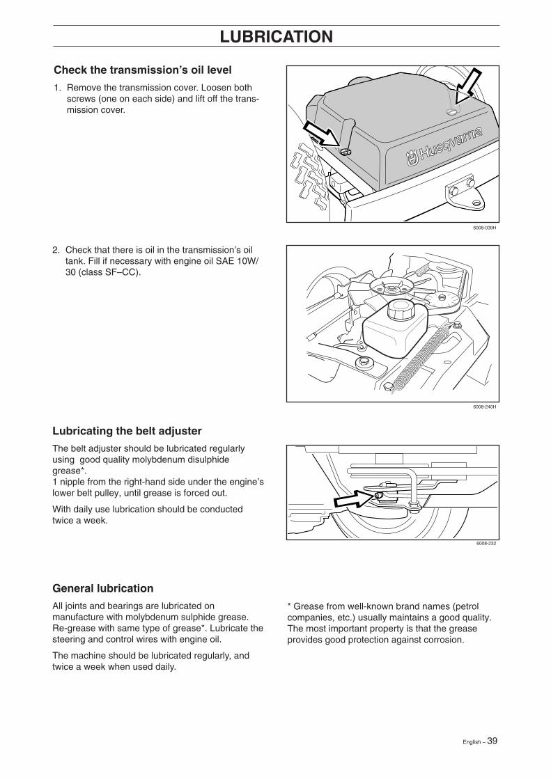
Check the transmission’s oil level
1. Remove the transmission cover. Loosen bothscrews (one on each side) and lift off the trans-mission cover.
2. Check that there is oil in the transmission’s oiltank. Fill if necessary with engine oil SAE 10W/30 (class SF–CC).
* Grease from well-known brand names (petrolcompanies, etc.) usually maintains a good quality.The most important property is that the greaseprovides good protection against corrosion.
6008-039H
6008-240H
6008-232

40 – English
Problem Procedure
Engine will not start. • Fuel tank empty.• Plug defective.• Plug connection defective.• Dirt in carburettor or fuel pipe.
Starter does not pull round engine. • Battery flat.• Bad contact between cable and battery terminal.• Lift lever for cutting unit in wrong position.• Main fuse blown. The fuse is placed in front of the
battery, under the battery cover.• Ignition lock faulty.• Gear shift/hydrostat pedal not in neutral.• Hydrostat pedals not in the neutral position
Engine does not run smoothly. • Wrong gear, too high.• Carburettor incorrectly set.• Air filter clogged.• Fuel tank vent blocked.• Ignition setting defective.• Dirt in fuel pipe.• Choking or incorrectly adjusted throttle cable
Engine seems to have no power. • Air filter clogged.• Plug defective.• Dirt in carburettor or fuel pipe.• Carburettor incorrectly set.• Choking or incorrectly adjusted throttle cable
Engine overheats. • Engine overloaded.• Air intake or cooling flanges blocked.• Fan damaged.• Too little or no oil in engine.• Ignition defective.• Plug defective.
Battery does not charge. • One or more cells faulty• Bad contact between battery terminals and cables.
Machine vibrates. • Blades are loose.• Engine is loose.• Imbalance on one or more blades, resulting from
damage or inferior balancing after sharpening.
Uneven mowing. • Blades blunt.• Cutting unit skew.• Long or wet grass.• Grass blockage under hood.• Different tyre pressures on right and left sides.• Over-speeding• Drive belts slipping.• The blade has a broken break-pin (BioClip)
TROUBLE SHOOTING SCHEDULE

English – 41
Winter storage
At the end of the season the machine shouldimmediately be put in order for storage, also if it isgoing to stand idle for more than 30 days. Fuelwhich is left to stand for long periods (30 days ormore) can leave tacky deposits which can blockthe carburettor and interfere with the engine.
Fuel stabiliser is an acceptable alternative to avoidtacky deposits during storage. If alkylate petrol(Aspen) is used stabiliser is not necessary sincethis fuel is stable. However, one should avoidchanging from standard to alkylate petrol sincesensitive rubber parts can harden. Add stabiliser tothe fuel in the tank or the storage container. Alwaysuse the mixing ratios indicated by the manufacturer.Run the engine for at least 10 minutes after addingthe stabiliser so that it will reach the carburettor. Donot empty the fuel tank and carburettor if stabiliserhas been added.
STORAGE
WARNING!Never place an engine with fuel inthe tank indoors or in poorlyventilated areas where petrolfumes can come into contact withnaked flames, sparks or pilotflames in boilers, hot waterheaters, ordrying cabinets, etc. It is highlyinflammable and negligent usagecan cause severe person injuryand material damage. Drain offthe fuel in an approved containeroutdoors and well clear of nakedflames. Never use petrol forcleaning purposes. Use degrea-sing agents and hot waterinstead.
To put the machine in order for storage follow theseinstructions:
1. Carefully clean the machine, especially underthe cutting unit. Touch-up paint damage to avoidrust.
2. Inspect the machine for worn or damaged partsand tighten loose screws and nuts.
3. Change the oil, and take care of the waste oil.
4. Empty the fuel tank. Start the engine and run ituntil the carburettor is emptied of fuel.
5. Remove the spark plug and pour about atablespoon of engine oil in the cylinder. Turnover the engine so that the oil is evenlydistributed and then refit the spark plug.
6. Grease all grease nipples, joints and axles.
7. Remove the battery. Clean it, charge it, andstore it is a cool place.
8. Store the machine is a clean and dry place andcover it over for extra protection.
Service
When ordering spare parts state the purchase year,model, type, and serial number.
Always use genuine parts.
Annual inspection or trimming by an authorisedservice workshop is a good way of getting the bestout of your machine the next season.
6017-213
42 – English
Dimensions Rider 16
Length without cutting unit 2145 mmWidth without cutting unit 1050 mmHeight 1060 mmService weight 247-260 kg including unitWheel base 855 mmTrack Front 715 mm, rear 625 mmTyre size 16 x 6.50 x 8Tyre pressure, front 60 kPa (0.6 kp/cm2)& rearMax. gradient 15°
Engine
Manufacture Briggs & Stratton model 28N707Power 11.4/15.5 kW/h.p.Displacement 465 cm3
Fuel Min. 85 octane unleadedTank volume 7 litresOil SAE 30 or SAE 10W/30 class SF-CCOil volume 1.2 litresStart Electric starter
Noise emissions and cutting width
Measured noise level 100 dB(A), (Rear 97; 98 dB(A))Guaranteed noise level 100 dB(A)Cutting width 900 - 1120 mm
Electrical system
Type 12 V, negative earthBattery 12 V. 24 AhSpark plug Champion CJ8 or J8, electrode gap = 0.7-0.8 mm
Transmission
Manufacture Tuff Torq K46Oil SAE 10W/30, class SF-CC
Cutting unit
Type 3-blade hood with side/rear ejection/BioClip 103/Combi2-blade hood BioClip 900 mm
Cutting width 900 mm (BioClip), 970 mm, 1030 mm (BioClip), 1120 mm (Combi)Cutting heights 9 positions, 40-90 mm, 45-95 mm (BioClip)Blade diameter 350 mm (Side), 410 mm (BioClip103), 420 mm (Combi 112),
440 mm (BioClip 90)
TECHNICAL DATA
We reserve the right to change technical specifications without prior notice.
Note that no legal claims are valid on the basis of information in this manual.
Use only genuine parts for repairs. The warranty is not valid if non genuine parts are used.
When this product is worn out or no longer used it should be returned tothe dealer or other appropriate body for recycling.

English – 43
EU-DECLARATION OF CONFORMITY
EU declaration of conformity (Only applies to Europe)
Husqvarna AB, SE-561 82 Huskvarna, Sweden, tel: +46-36-146500, declares under sole responsibility that theHusqvarna Rider 16, from 2002’s serial numbers and onwards (the year is clearly stated in plain text on the ratingplate with subsequent serial number), complies with the requirements of the COUNCIL’S DIRECTIVES:
- of June 22, 1998 ”relating to machinery” 98/37/EC, annex IIA.- of May 3, 1989 ”relating to electromagnetic compatibility” 89/336/EEC, and applicable supplements.- of May 8, 2000 ”relating to the emission of noise to surroundings” 2000/14/EC.Information regarding noise emissions and the mowing width, see the Technical Data.
The following harmonised standards have been applied: EN292-2, EN836.
The registered body 0404, SMP Svensk Maskinprovning AB, Fyrisborgsgatan 3, SE-754 50 Uppsala, Sweden hasissued the report with number 01/901/007, 01/901/008 regarding the assessment of conformity according to annex VIto the COUNCIL’S DIRECTIVE of May 8, 2000 ”relating to the emission of noise to surroundings” 2000/14/EC.
Huskvarna January 3, 2002
Roger Andersson, Development Manager/Garden Products

44 – English
SERVICEJOURNAL RIDER 16
Work done
Pre-delivery service
1. Top up battery with acid and recharge for four hours.
2. Fit steering wheel, seat and any optional equipment.
3. Adjust cutting unit:
Adjust the lifting springs (the “weight” of the cutting unit shouldbe 12-15 kg). Only applies to BioClip.
Adjust cutting unit so that rear edge is about 2–4 mm higherthan front edge.
Adjust cutting unit height setting so that cutting height limit is5 mm above the frame of the unit at the lowest cutting height.
4. Check that engine has correct amount of oil.
5. Check that the right amount of oil is in the transmission.
6. Check and adjust tyre pressure (60 kPa, 0.6 bar).
7. Connect battery.
8. Fill with fuel and start engine.
9. Check that machine does not move in neutral.
10. Check:
Forward drive.
Reverse drive.
Operation of blades.
Seat safety switch.
Lift lever safety switch.
Safety switch for the hydrostat pedals.
11. Check engine revs 2 950 rpm.
12. Tell customer about:
Need and benefits of following the service schedule.
The need and advantages of leaving the machine for regularservice.
The effects of maintenance on the machine’s second handvalue.
Range of applications for BioClip.
13. Complete proof of sale, etc.
Pre-delivery service carried out.
No outstanding problems.
Certified:
After first 5 hours
1. Change engine oil.
Date, mileage, stamp, sign
English – 45
○ ○ ○ ○ ○ ○ ○ ○ ○ ○ ○ ○ ○ ○ ○ ○ ○ ○ ○ ○ ○ ○ ○ ○ ○ ○ ○ ○ ○ ○ ○ ○ ○ ○ ○ ○ ○ ○ ○ ○ ○ ○ ○ ○ ○ ○ ○ ○ ○ ○ ○ ○ ○ ○ ○ ○ ○ ○ ○ ○ ○
○ ○ ○ ○ ○ ○ ○ ○ ○ ○ ○ ○ ○ ○ ○ ○ ○ ○ ○ ○ ○ ○ ○ ○ ○ ○ ○ ○ ○ ○ ○ ○ ○ ○ ○ ○ ○ ○ ○ ○ ○ ○ ○ ○ ○ ○ ○ ○ ○ ○ ○ ○ ○ ○ ○ ○ ○ ○ ○ ○ ○
○ ○ ○ ○ ○ ○ ○ ○ ○ ○ ○ ○ ○ ○ ○ ○ ○ ○ ○ ○ ○ ○ ○ ○ ○ ○ ○ ○ ○ ○ ○ ○ ○ ○ ○ ○ ○ ○ ○ ○ ○ ○ ○ ○ ○ ○ ○ ○ ○ ○ ○ ○ ○ ○ ○ ○ ○ ○ ○ ○ ○○ ○ ○ ○ ○ ○ ○ ○ ○ ○ ○ ○ ○ ○ ○ ○ ○ ○ ○ ○ ○ ○ ○ ○ ○ ○ ○ ○ ○ ○ ○ ○ ○ ○ ○ ○ ○ ○ ○ ○ ○ ○ ○ ○ ○ ○ ○ ○ ○ ○ ○ ○ ○ ○ ○ ○ ○ ○ ○ ○ ○
○ ○ ○ ○ ○ ○ ○ ○ ○ ○ ○ ○ ○ ○ ○ ○ ○ ○ ○ ○ ○ ○ ○ ○ ○ ○ ○ ○ ○ ○ ○ ○ ○ ○ ○ ○ ○ ○ ○ ○ ○ ○ ○ ○ ○ ○ ○ ○ ○ ○ ○ ○ ○ ○ ○ ○ ○ ○ ○ ○ ○
○ ○ ○ ○ ○ ○ ○ ○ ○ ○ ○ ○ ○ ○ ○ ○ ○ ○ ○ ○ ○ ○ ○ ○ ○ ○ ○ ○ ○ ○ ○ ○ ○ ○ ○ ○ ○ ○ ○ ○ ○ ○ ○ ○ ○ ○ ○ ○ ○ ○ ○ ○ ○ ○ ○ ○ ○ ○ ○ ○ ○
○ ○ ○ ○ ○ ○ ○ ○ ○ ○ ○ ○ ○ ○ ○ ○ ○ ○ ○ ○ ○ ○ ○ ○ ○ ○ ○ ○ ○ ○ ○ ○ ○ ○ ○ ○ ○ ○ ○ ○ ○ ○ ○ ○ ○ ○ ○ ○ ○ ○ ○ ○ ○ ○ ○ ○ ○ ○ ○ ○ ○
○ ○ ○ ○ ○ ○ ○ ○ ○ ○ ○ ○ ○ ○ ○ ○ ○ ○ ○ ○ ○ ○ ○ ○ ○ ○ ○ ○ ○ ○ ○ ○ ○ ○ ○ ○ ○ ○ ○ ○ ○ ○ ○ ○ ○ ○ ○ ○ ○ ○ ○ ○ ○ ○ ○ ○ ○ ○ ○ ○ ○
○ ○ ○ ○ ○ ○ ○ ○ ○ ○ ○ ○ ○ ○ ○ ○ ○ ○ ○ ○ ○ ○ ○ ○ ○ ○ ○ ○ ○ ○ ○ ○ ○ ○ ○ ○ ○ ○ ○ ○ ○ ○ ○ ○ ○ ○ ○ ○ ○ ○ ○ ○ ○ ○ ○ ○ ○ ○ ○ ○ ○
○ ○ ○ ○ ○ ○ ○ ○ ○ ○ ○ ○ ○ ○ ○ ○ ○ ○ ○ ○ ○ ○ ○ ○ ○ ○ ○ ○ ○ ○ ○ ○ ○ ○ ○ ○ ○ ○ ○ ○ ○ ○ ○ ○ ○ ○ ○ ○ ○ ○ ○ ○ ○ ○ ○ ○ ○ ○ ○ ○ ○
○ ○ ○ ○ ○ ○ ○ ○ ○ ○ ○ ○ ○ ○ ○ ○ ○ ○ ○ ○ ○ ○ ○ ○ ○ ○ ○ ○ ○ ○ ○ ○ ○ ○ ○ ○ ○ ○ ○ ○ ○ ○ ○ ○ ○ ○ ○ ○ ○ ○ ○ ○ ○ ○ ○ ○ ○ ○ ○ ○ ○
○ ○ ○ ○ ○ ○ ○ ○ ○ ○ ○ ○ ○ ○ ○ ○ ○ ○ ○ ○ ○ ○ ○ ○ ○ ○ ○ ○ ○ ○ ○ ○ ○ ○ ○ ○ ○ ○ ○ ○ ○ ○ ○ ○ ○ ○ ○ ○ ○ ○ ○ ○ ○ ○ ○ ○ ○ ○ ○ ○ ○
○ ○ ○ ○ ○ ○ ○ ○ ○ ○ ○ ○ ○ ○ ○ ○ ○ ○ ○ ○ ○ ○ ○ ○ ○ ○ ○ ○ ○ ○ ○ ○ ○ ○ ○ ○ ○ ○ ○ ○ ○ ○ ○ ○ ○ ○ ○ ○ ○ ○ ○ ○ ○ ○ ○ ○ ○ ○ ○ ○ ○
○ ○ ○ ○ ○ ○ ○ ○ ○ ○ ○ ○ ○ ○ ○ ○ ○ ○ ○ ○ ○ ○ ○ ○ ○ ○ ○ ○ ○ ○ ○ ○ ○ ○ ○ ○ ○ ○ ○ ○ ○ ○ ○ ○ ○ ○ ○ ○ ○ ○ ○ ○ ○ ○ ○ ○ ○ ○ ○ ○ ○
○ ○ ○ ○ ○ ○ ○ ○ ○ ○ ○ ○ ○ ○ ○ ○ ○ ○ ○ ○ ○ ○ ○ ○ ○ ○ ○ ○ ○ ○ ○ ○ ○ ○ ○ ○ ○ ○ ○ ○ ○ ○ ○ ○ ○ ○ ○ ○ ○ ○ ○ ○ ○ ○ ○ ○ ○ ○ ○ ○ ○
○ ○ ○ ○ ○ ○ ○ ○ ○ ○ ○ ○ ○ ○ ○ ○ ○ ○ ○ ○ ○ ○ ○ ○ ○ ○ ○ ○ ○ ○ ○ ○ ○ ○ ○ ○ ○ ○ ○ ○ ○ ○ ○ ○ ○ ○ ○ ○ ○ ○ ○ ○ ○ ○ ○ ○ ○ ○ ○ ○ ○
○ ○ ○ ○ ○ ○ ○ ○ ○ ○ ○ ○ ○ ○ ○ ○ ○ ○ ○ ○ ○ ○ ○ ○ ○ ○ ○ ○ ○ ○ ○ ○ ○ ○ ○ ○ ○ ○ ○ ○ ○ ○ ○ ○ ○ ○ ○ ○ ○ ○ ○ ○ ○ ○ ○ ○ ○ ○ ○ ○ ○
○ ○ ○ ○ ○ ○ ○ ○ ○ ○ ○ ○ ○ ○ ○ ○ ○ ○ ○ ○ ○ ○ ○ ○ ○ ○ ○ ○ ○ ○ ○ ○ ○ ○ ○ ○ ○ ○ ○ ○ ○ ○ ○ ○ ○ ○ ○ ○ ○ ○ ○ ○ ○ ○ ○ ○ ○ ○ ○ ○ ○
○ ○ ○ ○ ○ ○ ○ ○ ○ ○ ○ ○ ○ ○ ○ ○ ○ ○ ○ ○ ○ ○ ○ ○ ○ ○ ○ ○ ○ ○ ○ ○ ○ ○ ○ ○ ○ ○ ○ ○ ○ ○ ○ ○ ○ ○ ○ ○ ○ ○ ○ ○ ○ ○ ○ ○ ○ ○ ○ ○ ○
○ ○ ○ ○ ○ ○ ○ ○ ○ ○ ○ ○ ○ ○ ○ ○ ○ ○ ○ ○ ○ ○ ○ ○ ○ ○ ○ ○ ○ ○ ○ ○ ○ ○ ○ ○ ○ ○ ○ ○ ○ ○ ○ ○ ○ ○ ○ ○ ○ ○ ○ ○ ○ ○ ○ ○ ○ ○ ○ ○ ○
○ ○ ○ ○ ○ ○ ○ ○ ○ ○ ○ ○ ○ ○ ○ ○ ○ ○ ○ ○ ○ ○ ○ ○ ○ ○ ○ ○ ○ ○ ○ ○ ○ ○ ○ ○ ○ ○ ○ ○ ○ ○ ○ ○ ○ ○ ○ ○ ○ ○ ○ ○ ○ ○ ○ ○ ○ ○ ○ ○ ○
○ ○ ○ ○ ○ ○ ○ ○ ○ ○ ○ ○ ○ ○ ○ ○ ○ ○ ○ ○ ○ ○ ○ ○ ○ ○ ○ ○ ○ ○ ○ ○ ○ ○ ○ ○ ○ ○ ○ ○ ○ ○ ○ ○ ○ ○ ○ ○ ○ ○ ○ ○ ○ ○ ○ ○ ○ ○ ○ ○ ○
○ ○ ○ ○ ○ ○ ○ ○ ○ ○ ○ ○ ○ ○ ○ ○ ○ ○ ○ ○ ○ ○ ○ ○ ○ ○ ○ ○ ○ ○ ○ ○ ○ ○ ○ ○ ○ ○ ○ ○ ○ ○ ○ ○ ○ ○ ○ ○ ○ ○ ○ ○ ○ ○ ○ ○ ○ ○ ○ ○ ○
○ ○ ○ ○ ○ ○ ○ ○ ○ ○ ○ ○ ○ ○ ○ ○ ○ ○ ○ ○ ○ ○ ○ ○ ○ ○ ○ ○ ○ ○ ○ ○ ○ ○ ○ ○ ○ ○ ○ ○ ○ ○ ○ ○ ○ ○ ○ ○ ○ ○ ○ ○ ○ ○ ○ ○ ○ ○ ○ ○ ○
○ ○ ○ ○ ○ ○ ○ ○ ○ ○ ○ ○ ○ ○ ○ ○ ○ ○ ○ ○ ○ ○ ○ ○ ○ ○ ○ ○ ○ ○ ○ ○ ○ ○ ○ ○ ○ ○ ○ ○ ○ ○ ○ ○ ○ ○ ○ ○ ○ ○ ○ ○ ○ ○ ○ ○ ○ ○ ○ ○ ○
SERVICEJOURNAL
Work done Date, mileage, stamp, sign
46 – English
○ ○ ○ ○ ○ ○ ○ ○ ○ ○ ○ ○ ○ ○ ○ ○ ○ ○ ○ ○ ○ ○ ○ ○ ○ ○ ○ ○ ○ ○ ○ ○ ○ ○ ○ ○ ○ ○ ○ ○ ○ ○ ○ ○ ○ ○ ○ ○ ○ ○ ○ ○ ○ ○ ○ ○ ○ ○ ○ ○ ○
○ ○ ○ ○ ○ ○ ○ ○ ○ ○ ○ ○ ○ ○ ○ ○ ○ ○ ○ ○ ○ ○ ○ ○ ○ ○ ○ ○ ○ ○ ○ ○ ○ ○ ○ ○ ○ ○ ○ ○ ○ ○ ○ ○ ○ ○ ○ ○ ○ ○ ○ ○ ○ ○ ○ ○ ○ ○ ○ ○ ○
○ ○ ○ ○ ○ ○ ○ ○ ○ ○ ○ ○ ○ ○ ○ ○ ○ ○ ○ ○ ○ ○ ○ ○ ○ ○ ○ ○ ○ ○ ○ ○ ○ ○ ○ ○ ○ ○ ○ ○ ○ ○ ○ ○ ○ ○ ○ ○ ○ ○ ○ ○ ○ ○ ○ ○ ○ ○ ○ ○ ○○ ○ ○ ○ ○ ○ ○ ○ ○ ○ ○ ○ ○ ○ ○ ○ ○ ○ ○ ○ ○ ○ ○ ○ ○ ○ ○ ○ ○ ○ ○ ○ ○ ○ ○ ○ ○ ○ ○ ○ ○ ○ ○ ○ ○ ○ ○ ○ ○ ○ ○ ○ ○ ○ ○ ○ ○ ○ ○ ○ ○
○ ○ ○ ○ ○ ○ ○ ○ ○ ○ ○ ○ ○ ○ ○ ○ ○ ○ ○ ○ ○ ○ ○ ○ ○ ○ ○ ○ ○ ○ ○ ○ ○ ○ ○ ○ ○ ○ ○ ○ ○ ○ ○ ○ ○ ○ ○ ○ ○ ○ ○ ○ ○ ○ ○ ○ ○ ○ ○ ○ ○
○ ○ ○ ○ ○ ○ ○ ○ ○ ○ ○ ○ ○ ○ ○ ○ ○ ○ ○ ○ ○ ○ ○ ○ ○ ○ ○ ○ ○ ○ ○ ○ ○ ○ ○ ○ ○ ○ ○ ○ ○ ○ ○ ○ ○ ○ ○ ○ ○ ○ ○ ○ ○ ○ ○ ○ ○ ○ ○ ○ ○
○ ○ ○ ○ ○ ○ ○ ○ ○ ○ ○ ○ ○ ○ ○ ○ ○ ○ ○ ○ ○ ○ ○ ○ ○ ○ ○ ○ ○ ○ ○ ○ ○ ○ ○ ○ ○ ○ ○ ○ ○ ○ ○ ○ ○ ○ ○ ○ ○ ○ ○ ○ ○ ○ ○ ○ ○ ○ ○ ○ ○
○ ○ ○ ○ ○ ○ ○ ○ ○ ○ ○ ○ ○ ○ ○ ○ ○ ○ ○ ○ ○ ○ ○ ○ ○ ○ ○ ○ ○ ○ ○ ○ ○ ○ ○ ○ ○ ○ ○ ○ ○ ○ ○ ○ ○ ○ ○ ○ ○ ○ ○ ○ ○ ○ ○ ○ ○ ○ ○ ○ ○
○ ○ ○ ○ ○ ○ ○ ○ ○ ○ ○ ○ ○ ○ ○ ○ ○ ○ ○ ○ ○ ○ ○ ○ ○ ○ ○ ○ ○ ○ ○ ○ ○ ○ ○ ○ ○ ○ ○ ○ ○ ○ ○ ○ ○ ○ ○ ○ ○ ○ ○ ○ ○ ○ ○ ○ ○ ○ ○ ○ ○
○ ○ ○ ○ ○ ○ ○ ○ ○ ○ ○ ○ ○ ○ ○ ○ ○ ○ ○ ○ ○ ○ ○ ○ ○ ○ ○ ○ ○ ○ ○ ○ ○ ○ ○ ○ ○ ○ ○ ○ ○ ○ ○ ○ ○ ○ ○ ○ ○ ○ ○ ○ ○ ○ ○ ○ ○ ○ ○ ○ ○
○ ○ ○ ○ ○ ○ ○ ○ ○ ○ ○ ○ ○ ○ ○ ○ ○ ○ ○ ○ ○ ○ ○ ○ ○ ○ ○ ○ ○ ○ ○ ○ ○ ○ ○ ○ ○ ○ ○ ○ ○ ○ ○ ○ ○ ○ ○ ○ ○ ○ ○ ○ ○ ○ ○ ○ ○ ○ ○ ○ ○
○ ○ ○ ○ ○ ○ ○ ○ ○ ○ ○ ○ ○ ○ ○ ○ ○ ○ ○ ○ ○ ○ ○ ○ ○ ○ ○ ○ ○ ○ ○ ○ ○ ○ ○ ○ ○ ○ ○ ○ ○ ○ ○ ○ ○ ○ ○ ○ ○ ○ ○ ○ ○ ○ ○ ○ ○ ○ ○ ○ ○
○ ○ ○ ○ ○ ○ ○ ○ ○ ○ ○ ○ ○ ○ ○ ○ ○ ○ ○ ○ ○ ○ ○ ○ ○ ○ ○ ○ ○ ○ ○ ○ ○ ○ ○ ○ ○ ○ ○ ○ ○ ○ ○ ○ ○ ○ ○ ○ ○ ○ ○ ○ ○ ○ ○ ○ ○ ○ ○ ○ ○
○ ○ ○ ○ ○ ○ ○ ○ ○ ○ ○ ○ ○ ○ ○ ○ ○ ○ ○ ○ ○ ○ ○ ○ ○ ○ ○ ○ ○ ○ ○ ○ ○ ○ ○ ○ ○ ○ ○ ○ ○ ○ ○ ○ ○ ○ ○ ○ ○ ○ ○ ○ ○ ○ ○ ○ ○ ○ ○ ○ ○
○ ○ ○ ○ ○ ○ ○ ○ ○ ○ ○ ○ ○ ○ ○ ○ ○ ○ ○ ○ ○ ○ ○ ○ ○ ○ ○ ○ ○ ○ ○ ○ ○ ○ ○ ○ ○ ○ ○ ○ ○ ○ ○ ○ ○ ○ ○ ○ ○ ○ ○ ○ ○ ○ ○ ○ ○ ○ ○ ○ ○
○ ○ ○ ○ ○ ○ ○ ○ ○ ○ ○ ○ ○ ○ ○ ○ ○ ○ ○ ○ ○ ○ ○ ○ ○ ○ ○ ○ ○ ○ ○ ○ ○ ○ ○ ○ ○ ○ ○ ○ ○ ○ ○ ○ ○ ○ ○ ○ ○ ○ ○ ○ ○ ○ ○ ○ ○ ○ ○ ○ ○
○ ○ ○ ○ ○ ○ ○ ○ ○ ○ ○ ○ ○ ○ ○ ○ ○ ○ ○ ○ ○ ○ ○ ○ ○ ○ ○ ○ ○ ○ ○ ○ ○ ○ ○ ○ ○ ○ ○ ○ ○ ○ ○ ○ ○ ○ ○ ○ ○ ○ ○ ○ ○ ○ ○ ○ ○ ○ ○ ○ ○
○ ○ ○ ○ ○ ○ ○ ○ ○ ○ ○ ○ ○ ○ ○ ○ ○ ○ ○ ○ ○ ○ ○ ○ ○ ○ ○ ○ ○ ○ ○ ○ ○ ○ ○ ○ ○ ○ ○ ○ ○ ○ ○ ○ ○ ○ ○ ○ ○ ○ ○ ○ ○ ○ ○ ○ ○ ○ ○ ○ ○
○ ○ ○ ○ ○ ○ ○ ○ ○ ○ ○ ○ ○ ○ ○ ○ ○ ○ ○ ○ ○ ○ ○ ○ ○ ○ ○ ○ ○ ○ ○ ○ ○ ○ ○ ○ ○ ○ ○ ○ ○ ○ ○ ○ ○ ○ ○ ○ ○ ○ ○ ○ ○ ○ ○ ○ ○ ○ ○ ○ ○
○ ○ ○ ○ ○ ○ ○ ○ ○ ○ ○ ○ ○ ○ ○ ○ ○ ○ ○ ○ ○ ○ ○ ○ ○ ○ ○ ○ ○ ○ ○ ○ ○ ○ ○ ○ ○ ○ ○ ○ ○ ○ ○ ○ ○ ○ ○ ○ ○ ○ ○ ○ ○ ○ ○ ○ ○ ○ ○ ○ ○
○ ○ ○ ○ ○ ○ ○ ○ ○ ○ ○ ○ ○ ○ ○ ○ ○ ○ ○ ○ ○ ○ ○ ○ ○ ○ ○ ○ ○ ○ ○ ○ ○ ○ ○ ○ ○ ○ ○ ○ ○ ○ ○ ○ ○ ○ ○ ○ ○ ○ ○ ○ ○ ○ ○ ○ ○ ○ ○ ○ ○
○ ○ ○ ○ ○ ○ ○ ○ ○ ○ ○ ○ ○ ○ ○ ○ ○ ○ ○ ○ ○ ○ ○ ○ ○ ○ ○ ○ ○ ○ ○ ○ ○ ○ ○ ○ ○ ○ ○ ○ ○ ○ ○ ○ ○ ○ ○ ○ ○ ○ ○ ○ ○ ○ ○ ○ ○ ○ ○ ○ ○
○ ○ ○ ○ ○ ○ ○ ○ ○ ○ ○ ○ ○ ○ ○ ○ ○ ○ ○ ○ ○ ○ ○ ○ ○ ○ ○ ○ ○ ○ ○ ○ ○ ○ ○ ○ ○ ○ ○ ○ ○ ○ ○ ○ ○ ○ ○ ○ ○ ○ ○ ○ ○ ○ ○ ○ ○ ○ ○ ○ ○
○ ○ ○ ○ ○ ○ ○ ○ ○ ○ ○ ○ ○ ○ ○ ○ ○ ○ ○ ○ ○ ○ ○ ○ ○ ○ ○ ○ ○ ○ ○ ○ ○ ○ ○ ○ ○ ○ ○ ○ ○ ○ ○ ○ ○ ○ ○ ○ ○ ○ ○ ○ ○ ○ ○ ○ ○ ○ ○ ○ ○
○ ○ ○ ○ ○ ○ ○ ○ ○ ○ ○ ○ ○ ○ ○ ○ ○ ○ ○ ○ ○ ○ ○ ○ ○ ○ ○ ○ ○ ○ ○ ○ ○ ○ ○ ○ ○ ○ ○ ○ ○ ○ ○ ○ ○ ○ ○ ○ ○ ○ ○ ○ ○ ○ ○ ○ ○ ○ ○ ○ ○
SERVICEJOURNAL
Work done Date, mileage, stamp, sign
English – 47
○ ○ ○ ○ ○ ○ ○ ○ ○ ○ ○ ○ ○ ○ ○ ○ ○ ○ ○ ○ ○ ○ ○ ○ ○ ○ ○ ○ ○ ○ ○ ○ ○ ○ ○ ○ ○ ○ ○ ○ ○ ○ ○ ○ ○ ○ ○ ○ ○ ○ ○ ○ ○ ○ ○ ○ ○ ○ ○ ○ ○
○ ○ ○ ○ ○ ○ ○ ○ ○ ○ ○ ○ ○ ○ ○ ○ ○ ○ ○ ○ ○ ○ ○ ○ ○ ○ ○ ○ ○ ○ ○ ○ ○ ○ ○ ○ ○ ○ ○ ○ ○ ○ ○ ○ ○ ○ ○ ○ ○ ○ ○ ○ ○ ○ ○ ○ ○ ○ ○ ○ ○
○ ○ ○ ○ ○ ○ ○ ○ ○ ○ ○ ○ ○ ○ ○ ○ ○ ○ ○ ○ ○ ○ ○ ○ ○ ○ ○ ○ ○ ○ ○ ○ ○ ○ ○ ○ ○ ○ ○ ○ ○ ○ ○ ○ ○ ○ ○ ○ ○ ○ ○ ○ ○ ○ ○ ○ ○ ○ ○ ○ ○○ ○ ○ ○ ○ ○ ○ ○ ○ ○ ○ ○ ○ ○ ○ ○ ○ ○ ○ ○ ○ ○ ○ ○ ○ ○ ○ ○ ○ ○ ○ ○ ○ ○ ○ ○ ○ ○ ○ ○ ○ ○ ○ ○ ○ ○ ○ ○ ○ ○ ○ ○ ○ ○ ○ ○ ○ ○ ○ ○ ○
○ ○ ○ ○ ○ ○ ○ ○ ○ ○ ○ ○ ○ ○ ○ ○ ○ ○ ○ ○ ○ ○ ○ ○ ○ ○ ○ ○ ○ ○ ○ ○ ○ ○ ○ ○ ○ ○ ○ ○ ○ ○ ○ ○ ○ ○ ○ ○ ○ ○ ○ ○ ○ ○ ○ ○ ○ ○ ○ ○ ○
○ ○ ○ ○ ○ ○ ○ ○ ○ ○ ○ ○ ○ ○ ○ ○ ○ ○ ○ ○ ○ ○ ○ ○ ○ ○ ○ ○ ○ ○ ○ ○ ○ ○ ○ ○ ○ ○ ○ ○ ○ ○ ○ ○ ○ ○ ○ ○ ○ ○ ○ ○ ○ ○ ○ ○ ○ ○ ○ ○ ○
○ ○ ○ ○ ○ ○ ○ ○ ○ ○ ○ ○ ○ ○ ○ ○ ○ ○ ○ ○ ○ ○ ○ ○ ○ ○ ○ ○ ○ ○ ○ ○ ○ ○ ○ ○ ○ ○ ○ ○ ○ ○ ○ ○ ○ ○ ○ ○ ○ ○ ○ ○ ○ ○ ○ ○ ○ ○ ○ ○ ○
○ ○ ○ ○ ○ ○ ○ ○ ○ ○ ○ ○ ○ ○ ○ ○ ○ ○ ○ ○ ○ ○ ○ ○ ○ ○ ○ ○ ○ ○ ○ ○ ○ ○ ○ ○ ○ ○ ○ ○ ○ ○ ○ ○ ○ ○ ○ ○ ○ ○ ○ ○ ○ ○ ○ ○ ○ ○ ○ ○ ○
○ ○ ○ ○ ○ ○ ○ ○ ○ ○ ○ ○ ○ ○ ○ ○ ○ ○ ○ ○ ○ ○ ○ ○ ○ ○ ○ ○ ○ ○ ○ ○ ○ ○ ○ ○ ○ ○ ○ ○ ○ ○ ○ ○ ○ ○ ○ ○ ○ ○ ○ ○ ○ ○ ○ ○ ○ ○ ○ ○ ○
○ ○ ○ ○ ○ ○ ○ ○ ○ ○ ○ ○ ○ ○ ○ ○ ○ ○ ○ ○ ○ ○ ○ ○ ○ ○ ○ ○ ○ ○ ○ ○ ○ ○ ○ ○ ○ ○ ○ ○ ○ ○ ○ ○ ○ ○ ○ ○ ○ ○ ○ ○ ○ ○ ○ ○ ○ ○ ○ ○ ○
○ ○ ○ ○ ○ ○ ○ ○ ○ ○ ○ ○ ○ ○ ○ ○ ○ ○ ○ ○ ○ ○ ○ ○ ○ ○ ○ ○ ○ ○ ○ ○ ○ ○ ○ ○ ○ ○ ○ ○ ○ ○ ○ ○ ○ ○ ○ ○ ○ ○ ○ ○ ○ ○ ○ ○ ○ ○ ○ ○ ○
○ ○ ○ ○ ○ ○ ○ ○ ○ ○ ○ ○ ○ ○ ○ ○ ○ ○ ○ ○ ○ ○ ○ ○ ○ ○ ○ ○ ○ ○ ○ ○ ○ ○ ○ ○ ○ ○ ○ ○ ○ ○ ○ ○ ○ ○ ○ ○ ○ ○ ○ ○ ○ ○ ○ ○ ○ ○ ○ ○ ○
○ ○ ○ ○ ○ ○ ○ ○ ○ ○ ○ ○ ○ ○ ○ ○ ○ ○ ○ ○ ○ ○ ○ ○ ○ ○ ○ ○ ○ ○ ○ ○ ○ ○ ○ ○ ○ ○ ○ ○ ○ ○ ○ ○ ○ ○ ○ ○ ○ ○ ○ ○ ○ ○ ○ ○ ○ ○ ○ ○ ○
○ ○ ○ ○ ○ ○ ○ ○ ○ ○ ○ ○ ○ ○ ○ ○ ○ ○ ○ ○ ○ ○ ○ ○ ○ ○ ○ ○ ○ ○ ○ ○ ○ ○ ○ ○ ○ ○ ○ ○ ○ ○ ○ ○ ○ ○ ○ ○ ○ ○ ○ ○ ○ ○ ○ ○ ○ ○ ○ ○ ○
○ ○ ○ ○ ○ ○ ○ ○ ○ ○ ○ ○ ○ ○ ○ ○ ○ ○ ○ ○ ○ ○ ○ ○ ○ ○ ○ ○ ○ ○ ○ ○ ○ ○ ○ ○ ○ ○ ○ ○ ○ ○ ○ ○ ○ ○ ○ ○ ○ ○ ○ ○ ○ ○ ○ ○ ○ ○ ○ ○ ○
○ ○ ○ ○ ○ ○ ○ ○ ○ ○ ○ ○ ○ ○ ○ ○ ○ ○ ○ ○ ○ ○ ○ ○ ○ ○ ○ ○ ○ ○ ○ ○ ○ ○ ○ ○ ○ ○ ○ ○ ○ ○ ○ ○ ○ ○ ○ ○ ○ ○ ○ ○ ○ ○ ○ ○ ○ ○ ○ ○ ○
○ ○ ○ ○ ○ ○ ○ ○ ○ ○ ○ ○ ○ ○ ○ ○ ○ ○ ○ ○ ○ ○ ○ ○ ○ ○ ○ ○ ○ ○ ○ ○ ○ ○ ○ ○ ○ ○ ○ ○ ○ ○ ○ ○ ○ ○ ○ ○ ○ ○ ○ ○ ○ ○ ○ ○ ○ ○ ○ ○ ○
○ ○ ○ ○ ○ ○ ○ ○ ○ ○ ○ ○ ○ ○ ○ ○ ○ ○ ○ ○ ○ ○ ○ ○ ○ ○ ○ ○ ○ ○ ○ ○ ○ ○ ○ ○ ○ ○ ○ ○ ○ ○ ○ ○ ○ ○ ○ ○ ○ ○ ○ ○ ○ ○ ○ ○ ○ ○ ○ ○ ○
○ ○ ○ ○ ○ ○ ○ ○ ○ ○ ○ ○ ○ ○ ○ ○ ○ ○ ○ ○ ○ ○ ○ ○ ○ ○ ○ ○ ○ ○ ○ ○ ○ ○ ○ ○ ○ ○ ○ ○ ○ ○ ○ ○ ○ ○ ○ ○ ○ ○ ○ ○ ○ ○ ○ ○ ○ ○ ○ ○ ○
○ ○ ○ ○ ○ ○ ○ ○ ○ ○ ○ ○ ○ ○ ○ ○ ○ ○ ○ ○ ○ ○ ○ ○ ○ ○ ○ ○ ○ ○ ○ ○ ○ ○ ○ ○ ○ ○ ○ ○ ○ ○ ○ ○ ○ ○ ○ ○ ○ ○ ○ ○ ○ ○ ○ ○ ○ ○ ○ ○ ○
○ ○ ○ ○ ○ ○ ○ ○ ○ ○ ○ ○ ○ ○ ○ ○ ○ ○ ○ ○ ○ ○ ○ ○ ○ ○ ○ ○ ○ ○ ○ ○ ○ ○ ○ ○ ○ ○ ○ ○ ○ ○ ○ ○ ○ ○ ○ ○ ○ ○ ○ ○ ○ ○ ○ ○ ○ ○ ○ ○ ○
○ ○ ○ ○ ○ ○ ○ ○ ○ ○ ○ ○ ○ ○ ○ ○ ○ ○ ○ ○ ○ ○ ○ ○ ○ ○ ○ ○ ○ ○ ○ ○ ○ ○ ○ ○ ○ ○ ○ ○ ○ ○ ○ ○ ○ ○ ○ ○ ○ ○ ○ ○ ○ ○ ○ ○ ○ ○ ○ ○ ○
○ ○ ○ ○ ○ ○ ○ ○ ○ ○ ○ ○ ○ ○ ○ ○ ○ ○ ○ ○ ○ ○ ○ ○ ○ ○ ○ ○ ○ ○ ○ ○ ○ ○ ○ ○ ○ ○ ○ ○ ○ ○ ○ ○ ○ ○ ○ ○ ○ ○ ○ ○ ○ ○ ○ ○ ○ ○ ○ ○ ○
○ ○ ○ ○ ○ ○ ○ ○ ○ ○ ○ ○ ○ ○ ○ ○ ○ ○ ○ ○ ○ ○ ○ ○ ○ ○ ○ ○ ○ ○ ○ ○ ○ ○ ○ ○ ○ ○ ○ ○ ○ ○ ○ ○ ○ ○ ○ ○ ○ ○ ○ ○ ○ ○ ○ ○ ○ ○ ○ ○ ○
○ ○ ○ ○ ○ ○ ○ ○ ○ ○ ○ ○ ○ ○ ○ ○ ○ ○ ○ ○ ○ ○ ○ ○ ○ ○ ○ ○ ○ ○ ○ ○ ○ ○ ○ ○ ○ ○ ○ ○ ○ ○ ○ ○ ○ ○ ○ ○ ○ ○ ○ ○ ○ ○ ○ ○ ○ ○ ○ ○ ○
SERVICEJOURNAL
Work done Date, mileage, stamp, sign
○ ○ ○ ○ ○ ○ ○ ○ ○ ○ ○ ○ ○ ○ ○ ○ ○ ○ ○ ○ ○ ○ ○ ○ ○ ○ ○ ○ ○ ○ ○ ○ ○ ○ ○ ○ ○ ○ ○ ○ ○ ○ ○ ○ ○ ○ ○ ○ ○ ○ ○ ○ ○ ○ ○ ○ ○ ○ ○ ○ ○
○ ○ ○ ○ ○ ○ ○ ○ ○ ○ ○ ○ ○ ○ ○ ○ ○ ○ ○ ○ ○ ○ ○ ○ ○ ○ ○ ○ ○ ○ ○ ○ ○ ○ ○ ○ ○ ○ ○ ○ ○ ○ ○ ○ ○ ○ ○ ○ ○ ○ ○ ○ ○ ○ ○ ○ ○ ○ ○ ○ ○
○ ○ ○ ○ ○ ○ ○ ○ ○ ○ ○ ○ ○ ○ ○ ○ ○ ○ ○ ○ ○ ○ ○ ○ ○ ○ ○ ○ ○ ○ ○ ○ ○ ○ ○ ○ ○ ○ ○ ○ ○ ○ ○ ○ ○ ○ ○ ○ ○ ○ ○ ○ ○ ○ ○ ○ ○ ○ ○ ○ ○○ ○ ○ ○ ○ ○ ○ ○ ○ ○ ○ ○ ○ ○ ○ ○ ○ ○ ○ ○ ○ ○ ○ ○ ○ ○ ○ ○ ○ ○ ○ ○ ○ ○ ○ ○ ○ ○ ○ ○ ○ ○ ○ ○ ○ ○ ○ ○ ○ ○ ○ ○ ○ ○ ○ ○ ○ ○ ○ ○ ○
○ ○ ○ ○ ○ ○ ○ ○ ○ ○ ○ ○ ○ ○ ○ ○ ○ ○ ○ ○ ○ ○ ○ ○ ○ ○ ○ ○ ○ ○ ○ ○ ○ ○ ○ ○ ○ ○ ○ ○ ○ ○ ○ ○ ○ ○ ○ ○ ○ ○ ○ ○ ○ ○ ○ ○ ○ ○ ○ ○ ○
○ ○ ○ ○ ○ ○ ○ ○ ○ ○ ○ ○ ○ ○ ○ ○ ○ ○ ○ ○ ○ ○ ○ ○ ○ ○ ○ ○ ○ ○ ○ ○ ○ ○ ○ ○ ○ ○ ○ ○ ○ ○ ○ ○ ○ ○ ○ ○ ○ ○ ○ ○ ○ ○ ○ ○ ○ ○ ○ ○ ○
○ ○ ○ ○ ○ ○ ○ ○ ○ ○ ○ ○ ○ ○ ○ ○ ○ ○ ○ ○ ○ ○ ○ ○ ○ ○ ○ ○ ○ ○ ○ ○ ○ ○ ○ ○ ○ ○ ○ ○ ○ ○ ○ ○ ○ ○ ○ ○ ○ ○ ○ ○ ○ ○ ○ ○ ○ ○ ○ ○ ○
○ ○ ○ ○ ○ ○ ○ ○ ○ ○ ○ ○ ○ ○ ○ ○ ○ ○ ○ ○ ○ ○ ○ ○ ○ ○ ○ ○ ○ ○ ○ ○ ○ ○ ○ ○ ○ ○ ○ ○ ○ ○ ○ ○ ○ ○ ○ ○ ○ ○ ○ ○ ○ ○ ○ ○ ○ ○ ○ ○ ○
○ ○ ○ ○ ○ ○ ○ ○ ○ ○ ○ ○ ○ ○ ○ ○ ○ ○ ○ ○ ○ ○ ○ ○ ○ ○ ○ ○ ○ ○ ○ ○ ○ ○ ○ ○ ○ ○ ○ ○ ○ ○ ○ ○ ○ ○ ○ ○ ○ ○ ○ ○ ○ ○ ○ ○ ○ ○ ○ ○ ○
○ ○ ○ ○ ○ ○ ○ ○ ○ ○ ○ ○ ○ ○ ○ ○ ○ ○ ○ ○ ○ ○ ○ ○ ○ ○ ○ ○ ○ ○ ○ ○ ○ ○ ○ ○ ○ ○ ○ ○ ○ ○ ○ ○ ○ ○ ○ ○ ○ ○ ○ ○ ○ ○ ○ ○ ○ ○ ○ ○ ○
○ ○ ○ ○ ○ ○ ○ ○ ○ ○ ○ ○ ○ ○ ○ ○ ○ ○ ○ ○ ○ ○ ○ ○ ○ ○ ○ ○ ○ ○ ○ ○ ○ ○ ○ ○ ○ ○ ○ ○ ○ ○ ○ ○ ○ ○ ○ ○ ○ ○ ○ ○ ○ ○ ○ ○ ○ ○ ○ ○ ○
○ ○ ○ ○ ○ ○ ○ ○ ○ ○ ○ ○ ○ ○ ○ ○ ○ ○ ○ ○ ○ ○ ○ ○ ○ ○ ○ ○ ○ ○ ○ ○ ○ ○ ○ ○ ○ ○ ○ ○ ○ ○ ○ ○ ○ ○ ○ ○ ○ ○ ○ ○ ○ ○ ○ ○ ○ ○ ○ ○ ○
○ ○ ○ ○ ○ ○ ○ ○ ○ ○ ○ ○ ○ ○ ○ ○ ○ ○ ○ ○ ○ ○ ○ ○ ○ ○ ○ ○ ○ ○ ○ ○ ○ ○ ○ ○ ○ ○ ○ ○ ○ ○ ○ ○ ○ ○ ○ ○ ○ ○ ○ ○ ○ ○ ○ ○ ○ ○ ○ ○ ○
○ ○ ○ ○ ○ ○ ○ ○ ○ ○ ○ ○ ○ ○ ○ ○ ○ ○ ○ ○ ○ ○ ○ ○ ○ ○ ○ ○ ○ ○ ○ ○ ○ ○ ○ ○ ○ ○ ○ ○ ○ ○ ○ ○ ○ ○ ○ ○ ○ ○ ○ ○ ○ ○ ○ ○ ○ ○ ○ ○ ○
○ ○ ○ ○ ○ ○ ○ ○ ○ ○ ○ ○ ○ ○ ○ ○ ○ ○ ○ ○ ○ ○ ○ ○ ○ ○ ○ ○ ○ ○ ○ ○ ○ ○ ○ ○ ○ ○ ○ ○ ○ ○ ○ ○ ○ ○ ○ ○ ○ ○ ○ ○ ○ ○ ○ ○ ○ ○ ○ ○ ○
○ ○ ○ ○ ○ ○ ○ ○ ○ ○ ○ ○ ○ ○ ○ ○ ○ ○ ○ ○ ○ ○ ○ ○ ○ ○ ○ ○ ○ ○ ○ ○ ○ ○ ○ ○ ○ ○ ○ ○ ○ ○ ○ ○ ○ ○ ○ ○ ○ ○ ○ ○ ○ ○ ○ ○ ○ ○ ○ ○ ○
○ ○ ○ ○ ○ ○ ○ ○ ○ ○ ○ ○ ○ ○ ○ ○ ○ ○ ○ ○ ○ ○ ○ ○ ○ ○ ○ ○ ○ ○ ○ ○ ○ ○ ○ ○ ○ ○ ○ ○ ○ ○ ○ ○ ○ ○ ○ ○ ○ ○ ○ ○ ○ ○ ○ ○ ○ ○ ○ ○ ○
○ ○ ○ ○ ○ ○ ○ ○ ○ ○ ○ ○ ○ ○ ○ ○ ○ ○ ○ ○ ○ ○ ○ ○ ○ ○ ○ ○ ○ ○ ○ ○ ○ ○ ○ ○ ○ ○ ○ ○ ○ ○ ○ ○ ○ ○ ○ ○ ○ ○ ○ ○ ○ ○ ○ ○ ○ ○ ○ ○ ○
○ ○ ○ ○ ○ ○ ○ ○ ○ ○ ○ ○ ○ ○ ○ ○ ○ ○ ○ ○ ○ ○ ○ ○ ○ ○ ○ ○ ○ ○ ○ ○ ○ ○ ○ ○ ○ ○ ○ ○ ○ ○ ○ ○ ○ ○ ○ ○ ○ ○ ○ ○ ○ ○ ○ ○ ○ ○ ○ ○ ○
○ ○ ○ ○ ○ ○ ○ ○ ○ ○ ○ ○ ○ ○ ○ ○ ○ ○ ○ ○ ○ ○ ○ ○ ○ ○ ○ ○ ○ ○ ○ ○ ○ ○ ○ ○ ○ ○ ○ ○ ○ ○ ○ ○ ○ ○ ○ ○ ○ ○ ○ ○ ○ ○ ○ ○ ○ ○ ○ ○ ○
○ ○ ○ ○ ○ ○ ○ ○ ○ ○ ○ ○ ○ ○ ○ ○ ○ ○ ○ ○ ○ ○ ○ ○ ○ ○ ○ ○ ○ ○ ○ ○ ○ ○ ○ ○ ○ ○ ○ ○ ○ ○ ○ ○ ○ ○ ○ ○ ○ ○ ○ ○ ○ ○ ○ ○ ○ ○ ○ ○ ○
○ ○ ○ ○ ○ ○ ○ ○ ○ ○ ○ ○ ○ ○ ○ ○ ○ ○ ○ ○ ○ ○ ○ ○ ○ ○ ○ ○ ○ ○ ○ ○ ○ ○ ○ ○ ○ ○ ○ ○ ○ ○ ○ ○ ○ ○ ○ ○ ○ ○ ○ ○ ○ ○ ○ ○ ○ ○ ○ ○ ○
○ ○ ○ ○ ○ ○ ○ ○ ○ ○ ○ ○ ○ ○ ○ ○ ○ ○ ○ ○ ○ ○ ○ ○ ○ ○ ○ ○ ○ ○ ○ ○ ○ ○ ○ ○ ○ ○ ○ ○ ○ ○ ○ ○ ○ ○ ○ ○ ○ ○ ○ ○ ○ ○ ○ ○ ○ ○ ○ ○ ○
○ ○ ○ ○ ○ ○ ○ ○ ○ ○ ○ ○ ○ ○ ○ ○ ○ ○ ○ ○ ○ ○ ○ ○ ○ ○ ○ ○ ○ ○ ○ ○ ○ ○ ○ ○ ○ ○ ○ ○ ○ ○ ○ ○ ○ ○ ○ ○ ○ ○ ○ ○ ○ ○ ○ ○ ○ ○ ○ ○ ○
○ ○ ○ ○ ○ ○ ○ ○ ○ ○ ○ ○ ○ ○ ○ ○ ○ ○ ○ ○ ○ ○ ○ ○ ○ ○ ○ ○ ○ ○ ○ ○ ○ ○ ○ ○ ○ ○ ○ ○ ○ ○ ○ ○ ○ ○ ○ ○ ○ ○ ○ ○ ○ ○ ○ ○ ○ ○ ○ ○ ○
SERVICEJOURNAL
Work done Date, mileage, stamp, sign
´+H$|¶6k¨

English – 49

114 00 49-26
2002W09´+H$|¶6k¨