optima user manual -...
TRANSCRIPT

i
Optima User ManualUniversal Programming System
096-0222-003

ii
January 2000 096-0222-003
Data I/O has made every attempt to ensure that the information in thisdocument is accurate and complete. Data I/O assumes no liability for errors,or for any incidental, consequential, indirect, or special damages, including,without limitation, loss of use, loss or alteration of data, delays, or lost profitsor savings, arising from the use of this document or the product which itaccompanies.
No part of this document may be reproduced or transmitted in any form or byany means, electronic or mechanical, for any purpose, without writtenpermission from Data I/O.
Data I/O Corporation10525 Willows Road N.E., P.O. Box 97046Redmond, Washington 98073-9746 USA425-881-6444
www.dataio.com
Acknowledgments:
Data I/O is a registered trademark and TaskLink is a trademark of Data I/OCorporation.
Data I/O Corporation acknowledges the trademarks of other organizations fortheir respective products or services mentioned in this document.
©1999/2000 Data I/O CorporationAll rights reserved

Optima User Manual
iii
TABLE OF CONTENTS
INTRODUCTION........................................................................................................1
WELCOME ...................................................................................................................1SYSTEM OVERVIEW.....................................................................................................3
Standard Features..................................................................................................3Computer Requirements.........................................................................................4
INSTALLING THE OPTIMA HARDWARE .........................................................................5Connecting the Programmer to Your Computer....................................................5Connecting the TOPs to Your Programmer...........................................................7
INSTALLING THE OPTIMA WINDOWS SOFTWARE..........................................................8RUNNING OPTIMA WINDOWS SELF-TEST AND CALIBRATION.....................................10INSTALLING THE OPTIMA-BOOSTER FOR A SLOW PRINTER PORT ...............................13
QUICK START..........................................................................................................15
GETTING STARTED ....................................................................................................15PROGRAMMING A MEMORY DEVICE BY READING A MASTER DEVICE......................16PROGRAMMING A MEMORY DEVICE BY LOADING A DATA FILE ...............................21PROGRAMMING A LOGIC DEVICE BY READING A MASTER DEVICE...........................28PROGRAMMING A LOGIC DEVICE BY LOADING A DATA FILE ....................................33PROGRAMMING A MEMORY DEVICE ON THE TOP432 BY READING A MASTER DEVICE..................................................................................................................................39PROGRAMMING A MEMORY DEVICE ON THE TOP432 BY LOADING A DATA FILE ....44

Optima User Manual
iv
OPTIMA PROM SOFTWARE................................................................................51
MAIN PROGRAMMING SCREEN ..................................................................................51THE FILE MENU ........................................................................................................53
File>Load ............................................................................................................54File>Save As........................................................................................................64
THE MEMORY MENU ................................................................................................65Memory>Edit.......................................................................................................66Memory>Swap Bytes ...........................................................................................69Memory>Address Range .....................................................................................70Memory>Checksum Options…............................................................................72Memory>Special Device Functions….................................................................73Memory>Device Serialization Options… ...........................................................74
THE DEVICE MENU ...................................................................................................79Device>Program..................................................................................................80Device>Read .......................................................................................................84Device>Blank Check ...........................................................................................85Device>Verify......................................................................................................86
THE SELECT DEVICE MENU.......................................................................................88THE OPTIONS MENU .................................................................................................94THE UTILITIES MENU ................................................................................................97
Utilities>Create Devicelist..................................................................................98THE HELP MENU.......................................................................................................99
OPTIMA PAL SOFTWARE..................................................................................101
MAIN PROGRAMMING SCREEN ................................................................................101THE FILE MENU ......................................................................................................104
File>Load ..........................................................................................................105File>Save As......................................................................................................106
THE MEMORY MENU ..............................................................................................107Memory>Edit.....................................................................................................108
THE DEVICE MENU .................................................................................................110Device> Program ..............................................................................................110Device>Read .....................................................................................................112Device>Blank Check .........................................................................................113Device>Verify....................................................................................................113Device>Secure...................................................................................................114Device>Test .......................................................................................................115
THE SELECT DEVICE MENU.....................................................................................117

Optima User Manual
v
THE OPTIONS MENU................................................................................................119Options>Continuity Check ................................................................................120Options>Blank Check........................................................................................120Options>Verify Options.....................................................................................122Options>Auto Security ......................................................................................123Options>Vectortest ............................................................................................123Options>Algorithm Options…...........................................................................124
THE UTILITIES MENU ..............................................................................................125Utilities>Create Devicelist................................................................................126
THE HELP MENU.....................................................................................................127
SINGLE, GANG, AND SWAP PROGRAMMING ..............................................128
PROCESSING DEVICES IN THE SINGLE PROGRAMMING MODE ..................................129PROCESSING DEVICES IN THE GANG PROGRAMMING MODE ....................................131PROCESSING DEVICES IN THE SWAP PROGRAMMING MODE.....................................133
SET PROGRAMMING ON THE TOP432...........................................................136
8 Bit Mode..........................................................................................................13816 Bit Mode........................................................................................................13832 Bit Mode........................................................................................................139
SOFTWARE MAINTENANCE PLAN .................................................................140
UPDATING THE SOFTWARE MAINTENANCE PLAN ....................................................140

Optima User Manual
vi

INTRODUCTION
Optima User Manual
1
INTRODUCTION
Welcome
Congratulations on purchasing this Data I/O programmer. You are about to discoverthe ease of use and flexibility that make Data I/O programmers the leading choice forprofessional users.
This Optima User Manual will lead you through the process of setting up and runningany of these engineering and production products programmers in the Optima family:
Singlesyte MultisytePlus 48 DualOptima QuadOptima Light Octal
Whether Singlesyte or Multisyte, all Optima family programmers are controlled withthe same simple, intuitive screen controls of the Optima Windows software.
All Optima family programmers (with the exception of the Plus 48) will accept any ofthe interchangeable TOP Socket Modules or Production Adapters. A few of the TOPSocket Modules and Production Adapters are listed here:
TOP Socket ModulesTOP84PLC TOP3PLCTOP44PLC TOP68PLCTOP48DIP TOP432DIP
FlashTOP
Production AdaptersUniversal Adapter BaseUniversal SOIC Production AdapterAdditional Production Adapters tosupport TSOPs, BGAs, QFPs andothers.

INTRODUCTION
Optima User Manual
2
To use this universal hardware and software you simply connect the programmer andTOP to your computer, install the software, and you’re ready to begin programming.Your Windows dialog box will graphically display which programmer and TOP youare using.
Note: Most of the software commands described in the OptimaUser Manual apply to all programmers in the Optimafamily. If a command or operation applies to only one of theprogrammers, a special Note will alert you. If there is nospecial Note, then the same command works with allprogrammers.

INTRODUCTION
Optima User Manual
3
System Overview
As a peripheral to your PC, the programmer utilizes the RAM, CPU, and disk drivesin your computer for user interface and data exchange. The programmer comes withits own power supply (internal or external) and timing circuits for accurate generationof programming signals.
Standard Features
Standard features of the Optima programmers include:
High Pin Count: Up to 84 pins. Standard 48 pin (300/600 mil) DIP socketsupports devices from 8-48 pins. Additional pin drivers, if required, reside inthe individual TOPs.
Universal ASIC Pin Drivers: These provide precise digital and analogsignals on every pin. Controlled rise times and advanced noise suppressioncircuitry assure high quality, reliable programming.
Quick Response: Single keystroke operation and instantaneous file loadtimes make Optima both quick to learn and easy to use.
Device Support: PROMs, EPROMs, EEPROMs, PLDs, EPLDs, EEPLDs,GALs, FPLAs, IFLs, MCUs, Flash and more in 3 and 5 volt technologies, andin various package types.
PC Peripheral: Optima uses the computer’s existing RAM, Disk, Keyboardand Display to provide maximum price/performance.
Relay Power/Ground: Optimal noise-free device power for highest yields.
Fast Clock: Fast rise times (3 ns) allow reliable vector testing.
State Machine Waveform Generation: Internal crystal controlled state-machine ensures accurate programming waveforms not dependent on PCtiming.
Full Screen Menus: These make the Optima easy to learn and operate.
Customize User Interface Option: All input commands can be executedfrom a batch file, or via a network or multitasking Windows environment, ona local or remote PC.

INTRODUCTION
Optima User Manual
4
Computer Requirements
In order to use your programmer successfully, you will need the following:
Windows-based PC, AT, 486, Pentium, Laptop, or Notebook
640K RAM (minimum)
Hard disk with at least 10 Megabytes of available space
VGA or LCD

INTRODUCTION
Optima User Manual
5
Installing the Optima Hardware Optima programmers arrive with the following components:
Programmer base
Optional TOPs
25 pin, 1:1 parallel cable, 32” length
Optima-Booster
Power cord
Power supply (Plus 48, Optima, Optima Light, Dual)
Optima Windows software on CD-ROM
Optima User Manual
To prepare the Optima programmer for use, remove all the components from thepackaging material and verify that they are in good repair.
Connecting the Programmer to Your Computer
Connect the programmer to your computer by following these steps:
1. Make sure that both the computer and programmer power switches are turnedOFF.
2. Connect one end of the parallel cable to the port on the rear of the programmer. 3. Connect the other end of the parallel cable to the parallel port of your computer.
If your computer has more than one parallel port, any empty port may be used.
Note: Some parallel ports have hardware characteristics that maycause problems communicating with the programmer. If yousee the message “Found slow printer port” duringinstallation, install the Optima-Booster supplied with yourprogrammer. Follow the instructions “Installing theOptima-Booster for a Slow Printer Port.”

INTRODUCTION
Optima User Manual
6
4. Install the power supply: For Plus 48, Optima, Optima Light, and Dual programmers: Insert the small
DIN jack of the power supply into the power connector on the back of theprogrammer. This jack is keyed and cannot be inserted incorrectly.
Note: Power supplies for Plus 48, Optima, Optima Light and Dualare not interchangeable.
For Quad and Octal programmers: Connect the main power cord to thepower jack on the back of the programmer.
5. Insert the other end of the power cord into a 100-250 Volts, 50-60 Hz AC outlet.
Warning: Do not turn on the power

INTRODUCTION
Optima User Manual
7
Connecting the TOPs to Your Programmer
Programmers come with a variety of TOPs. If the TOP that came with yourprogrammer is not already installed, install it now following these steps:
1. Turn the TOP over and examine the pins to verify that they are straight. 2. Hold the TOP at a 45 angle to the programmer base, with the plastic tab of the
TOP hooked into the receiving indentation of the base. 3. Lower the TOP until it rests lightly on the base. 4. Rock the TOP gently until it seats into the base. 5. Press the TOP gently until you hear a click.
Warning: Do not press the TOP if you meet resistance. The pinsmay not be properly lined up with the pin connector stripon the base. If you meet resistance, remove TOP andbegin again at Step 1.
Note: You can arrange the TOPs in any order you want. It iscommon to arrange similar TOPs close to each other.
6. Turn the power switch on the back of the programmer to the ON position. 7. Turn the power switch on your computer to the ON position.

INTRODUCTION
Optima User Manual
8
Installing the Optima Windows Software
Follow these steps to install Optima Windows on your computer:
1. Insert the Optima Release CD-ROM into the appropriate drive on your computer.Windows starts the SetupWin.exe installation program and you will see theWelcome to Data I/O Windows Setup dialog box:
2. Select one of the listed options, then click OK:
Optima / Optima Light / Multisyte—most cases Plus 48—if connected to a programmer marked PLUS 48 Create installation disks—if installing onto a PC that does not have a CD-
ROM drive
Note: Do not select the Expert/Multisyte option. It is for olderhardware configurations that are not supported.
3. Click NEXT as you proceed through the Welcome and ReadMe Informationdialog boxes.

INTRODUCTION
Optima User Manual
9
4. Choose the destination location. We recommend that you select the defaultdirectory, C:\Optima.
5. Select TYPICAL on the Set-up Type dialog box. 6. Select the system folder where you wish to have the Optima software stored. The system creates the Optima window:
7. Drag the icons for Optima PAL, Optima PROM, Optima PROM432, and OptimaTEST to the Windows desktop.
8. Close all Optima applications.

INTRODUCTION
Optima User Manual
10
Running Optima Windows Self-Test and Calibration
After Optima Windows is installed you will need to initialize it so it can establishcommunications with the programmer and load the basic system configuration.
To run the Optima Windows Self-Test and Calibration, complete the following steps:
1. Make sure that all Optima applications are closed. 2. Double-click the Optima Test icon on the desktop to start the Self-Test. The
Self-Test & Calibration dialog box will be displayed:
3. Follow the instructions in the dialog box, then click OK or YES

INTRODUCTION
Optima User Manual
11
4. Click YES if the following window appears:
Note: If you see the message “Found slow printer port” during theSelf-Test, install the Optima-Booster according to theinstructions “Installing the Optima-Booster for a SlowPrinter Port.”
When the Self-Test has initialized the system, information such as the programmer’sserial number, the system type, and maintenance expiration date is displayed:

INTRODUCTION
Optima User Manual
12
5. Click YES to complete all the system tests. The system configuration and theresults of the tests are displayed on the screen when they are completed.
6. Close the test software if you are prompted to do so.

INTRODUCTION
Optima User Manual
13
Installing the Optima-Booster for a Slow Printer Port
You may have seen the message “Found slow printer port” during installation orduring the Self-Test. This message means that the parallel port is having a problemcommunicating with the programmer. As a solution, your system includes a piece ofhardware called the Optima-Booster, which has extra drive features and filters thatminimize hardware interference.
Follow these steps to install the Optima-Booster:
1. Make sure that both the computer and programmer power switches are turnedOFF.
2. Disconnect the parallel cable from the parallel port on the back of your computer. 3. Connect the PC-SIDE end of the Optima-Booster to the parallel port on your
computer.The Optima-Booster is keyed and cannot be connected incorrectly.
Warning: Do not connect the Optima-Booster to a COM, SCSI,or parallel (LPT) port/switch box. Otherwise damage tothe Optima-Booster or PC might result.
4. Connect the parallel cable to the other end of the Optima-Booster.
5. Turn the computer and programmer back ON.
Note: Some laptops do not provide enough power to have theOptima-Booster installed.

INTRODUCTION
Optima User Manual
14

QUICK START
Optima User Manual
15
QUICK START
Getting Started
Once the Optima software and hardware are successfully installed, you’re ready tobegin programming devices. The QUICK START section of the Optima User Manualguides you through programming memory or logic devices using Optima PROM,Optima PAL, or Optima PROM432 software.
First, choose the appropriate software. The software program you use depends onwhat type of device you will program, and what type of TOP you will use:
If you will program… then usea logic-based device Optima PAL softwarea memory-based device on a TOP432 Optima PROM432 softwareall other memory-based devices Optima PROM software
After you have selected the appropriate software, decide whether you will be fillingthe programmer’s RAM with valid programming data by
reading a Master Device, or loading a data file
The following sections take you through a step-by-step process of programming adevice. Find the section which matches your conditions and you’re on your way:
Programming a Memory Device by Reading a Master Device Programming a Memory Device by Loading a Data File Programming a Logic Device by Reading a Master Device Programming a Logic Device by Loading a Data File Programming a Memory Device on the TOP432 by Reading a Master Device Programming a Memory Device on the TOP432 by Loading a Data File
Note: An Optima programmer with a TOP48DIP is used in theexamples that follow.

QUICK START
Optima User Manual
16
Programming a Memory Device By Reading A Master Device
If you wish to program a memory-based device and you will be reading a MasterDevice, follow this procedure.
SELECT THE DEVICE YOU WISH TO PROGRAM:
Programming begins by selecting the device you wish to program. To select thedevice, follow these steps:
1. Double click the Optima PROM icon on the Windows desktop. The ChangeDevice window displays a device list for the specific TOP you are using.
2. Click on the name of the Vendor. When you do that, the Family and Device listsmay change.
3. Click on the general Family of devices. The Device list may change again basedof the Family you chose.
4. Click on a device part number from the Device list. In this example, anAMDAm28F010 is selected:

QUICK START
Optima User Manual
17
5. Click OK to save that selection and display the Main Programming screen:

QUICK START
Optima User Manual
18
READ A MASTER DEVICE:
After you have selected the device, you are ready to read the Master Device. To readthe Master Device, follow these steps:
1. Insert the Master Device in the TOP lit with the green LED.
2. Click Read Device.Data from the Master Device is loaded into the programmer’s RAM. When theload operation is complete, the Status area in the Main Programming screendisplays the word PASS and the checksum for the data loaded into RAM isdisplayed:

QUICK START
Optima User Manual
19
PROGRAM THE DEVICE
Now that you have loaded valid data into the programmer’s RAM by reading a MasterDevice, you’re ready to program the device. To program the device, follow thesesteps:
1. Remove the Master Device from the TOP.
2. Insert the device you wish to program into the TOP with the green LED. 3. Click Program. You will be asked if you wish to Start Programming Now.

QUICK START
Optima User Manual
20
4. Click YES.When the programming operation is complete, the Status area of the MainProgramming screen displays the word PASS:

QUICK START
Optima User Manual
21
Programming a Memory Device By Loading A Data File
If you wish to program a memory-based device and you will be loading a data file,follow this procedure.
SELECT THE DEVICE YOU WISH TO PROGRAM:
Programming begins by selecting the device you wish to program. To select thedevice, follow these steps:
1. Double click the Optima PROM icon on the Windows desktop. The ChangeDevice window displays a device list for the specific TOP you are using.
2. Click on the name of the Vendor. When you do that, the Family and Device listsmay change.
3. Click on the general Family of devices. The Device list may change again basedof the Family you chose.
4. Click on a device part number from the Device list. In this example, anAMDAm28F010 is selected:

QUICK START
Optima User Manual
22
5. Click OK to save that selection and display the Main Programming screen:

QUICK START
Optima User Manual
23
LOAD A DATA FILE:
After you have selected the device, you are ready to load a data file into RAM. Toload a data file, follow these steps:
1. Select File > Load from the main menu bar. The Open dialog box is displayed:
2. Browse through the “List files of type” box and select the appropriate programdata file name from the list on the screen.

QUICK START
Optima User Manual
24
3. Click OK. The File load options dialog box is then displayed:
4. Click OK. You’ll be asked Ready to load? Click YES

QUICK START
Optima User Manual
25
5. After the data has been loaded, you’ll see a screen that reports the status of theloading:

QUICK START
Optima User Manual
26
PROGRAM THE DEVICE
Now that you have loaded valid data into the programmer’s RAM by loading a datafile, you’re ready to program the device. To program the device, follow these steps:
1. Insert the device you wish to program into the TOP with the green LED. 2. Click Program. You will be asked if you wish to Start Programming Now.

QUICK START
Optima User Manual
27
3. Click YES.When the operation is complete, you will see the screen shown here:

QUICK START
Optima User Manual
28
Programming a Logic Device By Reading A Master Device
If you wish to program a logic-based device and you will be reading a Master Device,follow this procedure.
SELECT THE DEVICE YOU WISH TO PROGRAM:
Programming begins by selecting the device you wish to program. To select thedevice, follow these steps:
1. Double click the Optima PAL icon on the Windows desktop. The ChangeDevice window displays a device list for the specific TOP you are using.
2. Click on the name of the Vendor. When you do that, the Family and Device listsmay change.
3. Click on the general Family of devices. The Device list may change again basedof the Family you chose.
4. Click on a device part number from the Device list. In this example, a LatticeGAL20RA10 is selected:

QUICK START
Optima User Manual
29
5. Click OK to save that selection and display the Main Programming screen:

QUICK START
Optima User Manual
30
READ A MASTER DEVICE:
After you have selected the device, you are ready to read the Master Device. To readthe Master Device, follow these steps:
1. Insert the Master Device in the TOP lit with the green LED.
2. Click Read Device.Data from the Master Device is loaded into the programmer’s RAM. When theload operation is complete, the Status area in the Main Programming screendisplays the word PASS and the checksum for the data loaded into RAM isdisplayed:

QUICK START
Optima User Manual
31
PROGRAM THE DEVICE
Now that you have loaded valid data into the programmer’s RAM by reading a MasterDevice, you’re ready to program the device. To program the device, follow thesesteps:
1. Remove the Master Device from the TOP.
2. Insert the device you wish to program into the TOP with the green LED. 3. Click Program. You will be asked if you wish to Start Programming Now.

QUICK START
Optima User Manual
32
4. Click YES.When the programming operation is complete, the Status area of the MainProgramming screen displays the word PASS:

QUICK START
Optima User Manual
33
Programming a Logic Device By Loading A Data File
If you wish to program a logic-based device and you will be loading a data file, followthis procedure.
SELECT THE DEVICE YOU WISH TO PROGRAM:
Programming begins by selecting the device you wish to program. To select thedevice, follow these steps:
1. Double click the Optima PAL icon on the Windows desktop. The ChangeDevice window displays a device list for the specific TOP you are using.
2. Click on the name of the Vendor. When you do that, the Family and Device listsmay change.
3. Click on the general Family of devices. The Device list may change again basedof the Family you chose.
4. Click on a device part number from the Device list. In this example, a LatticeGAL20RA10 is selected:

QUICK START
Optima User Manual
34
5. Click OK to save that selection and display the Main Programming screen:

QUICK START
Optima User Manual
35
LOAD A DATA FILE:
After you have selected the device, you are ready to load a data file into RAM. Toload a data file, follow these steps:
1. Select File > Load from the main menu bar. The File Open dialog box isdisplayed:
2. Browse through the Files list and select the appropriate program data file name.

QUICK START
Optima User Manual
36
3. Click OK. The Main Programming screen is then displayed:

QUICK START
Optima User Manual
37
PROGRAM THE DEVICE
Now that you have loaded valid data into the programmer’s RAM by loading a datafile, you’re ready to program the device. To program the device, follow these steps:
1. Insert the device you wish to program into the TOP with the green LED.
2. Click Program. You will be asked if you wish to Start Programming Now.

QUICK START
Optima User Manual
38
3. Click YES.When the programming operation is complete, the Status area of the MainProgramming screen displays the word PASS:

QUICK START
Optima User Manual
39
Programming a Memory Device on the TOP432 By Reading AMaster Device
If you wish to program a memory-based device on the TOP432 and you will bereading a Master Device, follow this procedure.
SELECT THE DEVICE YOU WISH TO PROGRAM:
Programming begins by selecting the device you wish to program. To select thedevice, follow these steps:
1. Double click the Optima PROM432 icon on the Windows desktop. The ChangeDevice window displays a device list for the TOP432.
2. Click on the name of the Vendor. When you do that, the Family and Device listsmay change.
3. Click on the general Family of devices. The Device list may change again basedof the Family you chose.
4. Click on a device part number from the Device list. In this example, anAMDAm28F010 is selected:

QUICK START
Optima User Manual
40
5. Click OK to save that selection and display the Main Programming screen:

QUICK START
Optima User Manual
41
READ A MASTER DEVICE:
After you have selected the device, you are ready to read the Master Device. To readthe Master Device, follow these steps:
1. Insert the Master Device in the upper left-hand socket of the TOP432.
2. Click Read Device.Data from the Master Device is loaded into the programmer’s RAM. When theload operation is complete, the Status area in the Main Programming screendisplays the word PASS and the checksum for the data loaded into RAM isdisplayed:

QUICK START
Optima User Manual
42
PROGRAM THE DEVICE
Now that you have loaded valid data into the programmer’s RAM by reading a MasterDevice, you’re ready to program the device. To program the device, follow thesesteps:
1. Remove the Master Device from the TOP432.
2. Insert the devices you wish to program into the four sockets of the TOP432. 3. Click Program. You will be asked if you wish to Start Programming Now
.

QUICK START
Optima User Manual
43
4. Click YES.When the programming operation is complete, the Status area of the MainProgramming screen displays the word PASS:

QUICK START
Optima User Manual
44
Programming a Memory Device on the TOP432 By Loading AData File
If you wish to program a memory-based device on the TOP432 and you will beloading a data file, follow this procedure.
SELECT THE DEVICE YOU WISH TO PROGRAM:
Programming begins by selecting the device you wish to program. To select thedevice, follow these steps:
1. Double click the Optima PROM432 icon on the Windows desktop. The ChangeDevice window displays a device list for the TOP432.
2. Click on the name of the Vendor. When you do that, the Family and Device listsmay change.
3. Click on the general Family of devices. The Device list may change again basedof the Family you chose.

QUICK START
Optima User Manual
45
4. Click on a device part number from the Device list. In this example, anAMDAm28F010 is selected:

QUICK START
Optima User Manual
46
5. Click OK to save that selection and display the Main Programming screen:

QUICK START
Optima User Manual
47
LOAD A DATA FILE:
After you have selected the device, you are ready to load a data file into RAM. Toload a data file, follow these steps:
1. Select File > Load from the main menu bar. The Open dialog box is displayed:
2. Browse through the “List files of type” box and select the appropriate programdata file name from the list on the screen.
3. Click OK. The File load options dialog box is then displayed:

QUICK START
Optima User Manual
48
4. Click OK. You’ll be asked Ready to load? Click YES
5. After the data has been loaded, you’ll see a screen that reports the status of the
loading:

QUICK START
Optima User Manual
49
PROGRAM THE DEVICE
Now that you have loaded valid data into the programmer’s RAM by loading a datafile, you’re ready to program the device. To program the device, follow these steps:
1. Insert the devices you wish to program into the four sockets of the TOP432. 2. Click Program. You will be asked if you wish to Start Programming Now.

QUICK START
Optima User Manual
50
3. Click YES.When the programming operation is complete, the Status area of the MainProgramming screen displays the word PASS

OPTIMA PROM SOFTWARE
Optima User Manual
51
OPTIMA PROM SOFTWARE
This section of the Optima User Manual provides detailed descriptions of the OptimaPROM software used for programming memory devices. If you wish to get startedprogramming memory devices quickly, go to the QUICK START section of theOptima User Manual.
Main Programming Screen
Once the device has been selected, the Main Programming screen will appear. Thisscreen will provide you with programming information and controls.
PROM software Main Programming screen

OPTIMA PROM SOFTWARE
Optima User Manual
52
The Main Programming screen is divided into these areas:
File—contains information regarding the checksum of the data currently in RAMand the usable address range of the device. If a TOP432 is installed, the Mode:item will display its GANG or SET mode settings.
Device—contains information related to the device to be processed. The
Devicecode: field contains a unique identification code for the device selected.This code is used by the optional TaskLink Windows software.
OPTIMA Xx/XX—contains information about the PROM/PROM432 software
version, the TOPs installed on the programmer base and the status of each, andthe programming mode (single, gang, or swap).
Status—provides the status of the last device programmed(PASS/FAIL/CHECK), the total number of devices to be processed (this field iseditable), and the number of devices remaining to be processed.
Device Action—provides quick access to the most commonly used operations.
There are buttons for Program, Read Device, Blank Check, and Verifyoperations.
Additional information—contains any additional information that may berequired to process the selected devices, such as a specialized adapter, etc.
Next Ser.-No.—contains the next serial number to be applied to the device if the
serialization option has been enabled. Messages—contains any additional messages that describe various conditions
related to the processing of the selected device. Messages that may appearinclude references to specialized adapters, settings that have been changed totheir non-default conditions, and others.

OPTIMA PROM SOFTWARE
Optima User Manual
53
The File Menu The first menu on the Main Programming screen is the File menu. The File menu hastwo primary functions: loading data into RAM, and saving data from RAM.Additionally, the PROM software can be terminated from this menu using the Exitfunction:
The File menu

OPTIMA PROM SOFTWARE
Optima User Manual
54
File>Load Selecting File>Load will produce the Open dialog screen:
The Open dialogue The Open dialogue allows the use of these different data formats: Binary (*.com, *.bin) Hex (*.hex, *.obj, *mot, *.S*) which supports data formats in Motorola
Exorciser, Motorola ExorMax, Motorola 32 (S3), Intel Intellec 8/MDS, IntelMCS-86 Hex, Intel OMF 286, and Intel Hex-32
Space (*.spc) which supports ASCII Hex Space MOS (*.mos) which supports MOS Technology LOF (*.lof) which supports Quick Logic Actel (*.dio) HP64000 (*.hp) which supports HP64000 Absolute and HP Unix
Note: If Hex or HP Format is selected, the Optima softwareautomatically selects the appropriate format.

OPTIMA PROM SOFTWARE
Optima User Manual
55
If your data file does not use any of the predefined fileextensions, you can wild card the file name by using (*.*) inthe file name box and choosing the appropriate file type.
Navigate the computer or network for the required data file, and select the <OK>button. Once the file is selected, the File load options screen will appear:
File load options screen This dialogue provides options for file starting address, device memory destination,file mode, and data format. File Load Options For most file load operations you will accept the default values when the File loadoptions dialog box appears by clicking on <OK>. However, the File load optionsdialog box has four option menus that allow you to customize the file load operation:
Start address in file Destination in memory File mode Intel/Motorola format

OPTIMA PROM SOFTWARE
Optima User Manual
56
Start address in file: If a hexadecimal number is placed in the Start address in file box prior to a file loadoperation, the load software waits until that address is reached before placing data intothe Optima Ram Buffer. In Example 1 below, the Start address in file has been set to 300 hex, and thereforethe load software waits until address 300 hex has been reached before placing datainto the Optima Ram Buffer starting at location zero. Start address in file works for all formats.
Example 1: Start address in file
File Data (ASCII Hex Space) Optima Ram Buffer $A000, Address Data 00 01 02 03 04 05 06 07 0000 88 0001 99 $A100, 0002 AA 08 09 0A 0B 0C 0D 0E 0F 0003 BB 0004 CC $A200, 0005 DD 00 11 22 33 44 55 66 77 0006 EE 0007 FF $A300, 0008 xx 88 99 AA BB CC DD EE FF 0009 xx 000A xx 000B xx 000C xx Start address in file = 300 Hex 000D xx xx = Don’t Care 000E xx 000F xx

OPTIMA PROM SOFTWARE
Optima User Manual
57
Destination in memory: The hex value placed in the Destination in memory determines the starting point in theOptima Ram Buffer where data will be stored. Destination in memory works for all file formats. In Example 2 below the Destination in memory value is set to 800 hex; this causes thestart of the data file to be placed at 800 hex in the Optima Ram Buffer.
Example 2: Destination in memory
File Data (ASCII Hex Space) Optima Ram Buffer $A000, Address Data 00 01 02 03 04 05 06 07 0000 xx 0100 xx $A008, 0200 xx 08 09 0A 0B 0C 0D 0E 0F 0300 xx 0400 xx $A010, 0500 xx 00 11 22 33 44 55 66 77 0600 xx 0700 xx $A018, 0800 00 88 99 AA BB CC DD EE FF 0801 01 0802 02 0803 03 0804 04 Destination in memory = 800 Hex 0805 05 xx = Don’t Care 0806 06 0807 07

OPTIMA PROM SOFTWARE
Optima User Manual
58
File mode: This option allows you to rearrange the file data so that the data will fit in thetargeted-programmed device. For example, a 16-bit data file has to be programmedinto two 8-bit devices. File mode has five different ways to rearrange data: 8-Bit All—No effect on the incoming data. 8 Bit Merge Low and High—Used to merge two 8-bit files into one 16-bit file. 16-Bit Even and Odd—Used to program a 16-bit data file into two 8-bit devices. 32-Bit Byte 0, Byte 1, Byte 2, Byte 3—Used to program a 32-bit data file into
four 8-bit devices. 32-Bit Low and High Word—Used to program a 32-bit data file into two 16-bit
devices.
8-Bit AllWith 8-Bit All, the file data that is read is transferred directly into the Optima RamBuffer, as shown in Example 3 below.
Example 3: 8-Bit All
File Data Optima Ram Buffer
$A000, Address Data00 01 02 03 04 05 06 07 0000 00
0001 01$A008, 0002 0208 09 0A 0B 0C 0D 0E 0F 0003 03
0004 04$A010, 0005 0500 11 22 33 44 55 66 77 0006 06
0007 07$A018, 0008 0888 99 AA BB CC DD EE FF 0009 09
000A 0A000B 0B000C 0C000D 0D000E 0E000F 0F

OPTIMA PROM SOFTWARE
Optima User Manual
59
8-Bit Merge Low and High
This option is used to merge two 8-bit data files into one 16-bit data file, allowing a16-bit device to be programmed.
To merge two 8-bit files into one 16-bit file, follow this four step process:1. Select the first 8-bit file, choose 8-Bit Merge Low, and load your file.
The 8-bit data will be loaded at all the even addresses (shown in bold below).2. Select the second 8-bit file, choose 8-Bit Merge High, and load the file.
The 8-bit data will be loaded at all the odd addresses. (shown in italics below).3. Program the 16-bit memory device.4. Save the newly created 16-bit data file.
Example 4: 8-Bit Merge Low and High
File Data Optima Ram Buffer
$A000, (8-Bit file one) Address Data00 01 02 03 04 05 06 07 0000 00
0001 00$A008, 0002 0108 09 0A 0B 0C 0D 0E 0F 0003 11
0004 02$A000, (8 Bit file two) 0005 2200 11 22 33 44 55 66 77 0006 03
0007 33$A008, 0008 0488 99 AA BB CC DD EE FF 0009 44
000A 05000B 55000C 06000D 66000E 07000F 77
OPTIMA PROM SOFTWARE
Optima User Manual
60
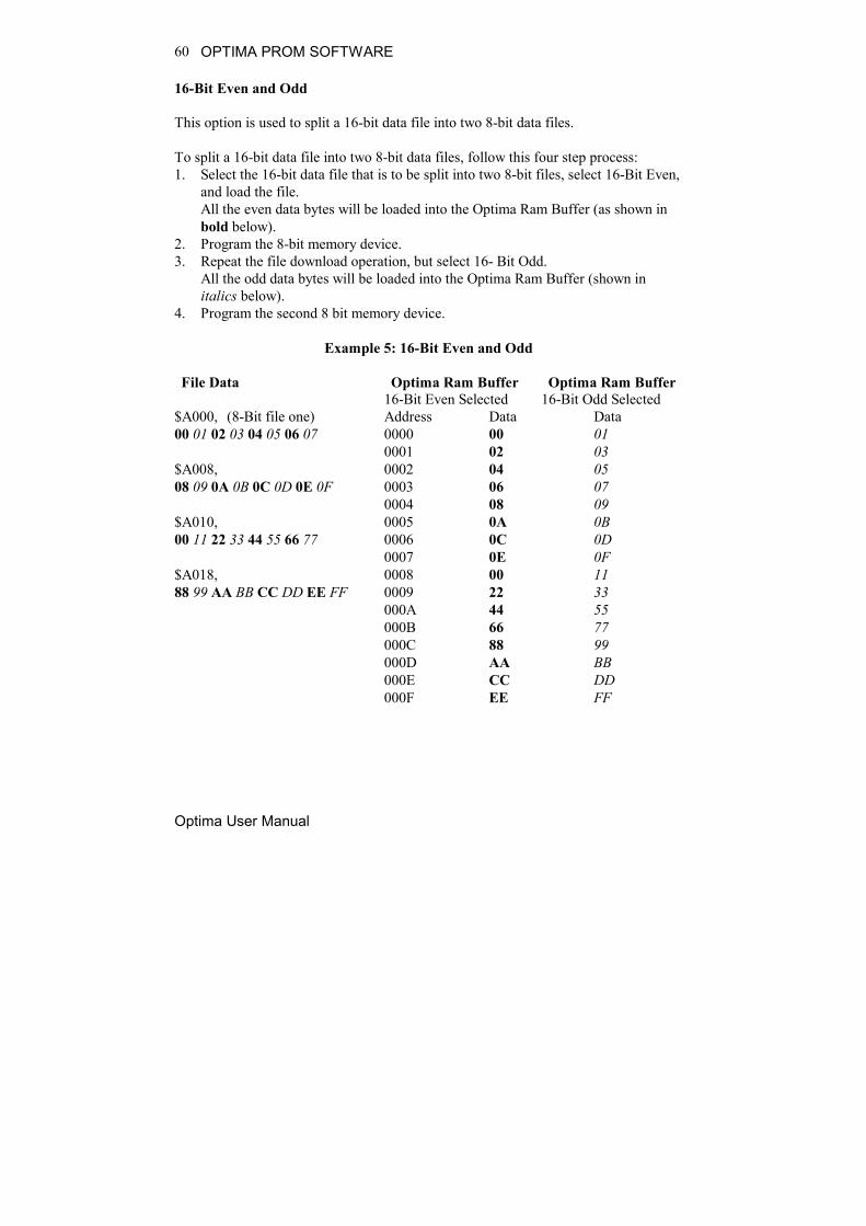
16-Bit Even and Odd
This option is used to split a 16-bit data file into two 8-bit data files.
To split a 16-bit data file into two 8-bit data files, follow this four step process:1. Select the 16-bit data file that is to be split into two 8-bit files, select 16-Bit Even,
and load the file.All the even data bytes will be loaded into the Optima Ram Buffer (as shown inbold below).
2. Program the 8-bit memory device.3. Repeat the file download operation, but select 16- Bit Odd.
All the odd data bytes will be loaded into the Optima Ram Buffer (shown initalics below).
4. Program the second 8 bit memory device.
Example 5: 16-Bit Even and Odd
File Data Optima Ram Buffer Optima Ram Buffer16-Bit Even Selected 16-Bit Odd Selected
$A000, (8-Bit file one) Address Data Data00 01 02 03 04 05 06 07 0000 00 01
0001 02 03$A008, 0002 04 0508 09 0A 0B 0C 0D 0E 0F 0003 06 07
0004 08 09$A010, 0005 0A 0B00 11 22 33 44 55 66 77 0006 0C 0D
0007 0E 0F$A018, 0008 00 1188 99 AA BB CC DD EE FF 0009 22 33
000A 44 55000B 66 77000C 88 99000D AA BB000E CC DD000F EE FF

OPTIMA PROM SOFTWARE
Optima User Manual
61
32-Bit Byte0…Byte3
This option is used to split a 32-bit data file into four 8-bit data files.
To split a 32-bit data file into four 8-bit data files, follow this eight-step process:1. Select the 32-Bit data file that is to be split into four 8-bit files, select 32-Bit Byte
0, and load the file. Data bytes D0-D7 will be loaded into Optima Ram Buffer(shown in bold).
2. Program the first 8-bit memory device.3. Repeat the file download operation, and select 32-Bit Byte 1.
Data bytes D8-D15 will be loaded into the Ram Buffer (shown in italics).4. Program the second 8-bit device.5. Repeat the file download operation, and select 32-Bit Byte 2.
Data bytes D16-D23 will be loaded into the Ram Buffer (shown in underline).6. Program the third 8-bit device.7. Repeat the file download operation a forth time, and select 32-Bit Byte 3.
Data bytes D24-D31 will be loaded into the Ram Buffer (shown in regular).8. Program the fourth 8-bit device.
Example 6: 32-Bit Byte0…Byte3
File Data Ram BufferByte 0 Byte 1 Byte 2 Byte 3
$A000, Address Data Data Data Data00 01 02 03 04 05 06 07 0000 00 01 02 03
0001 04 05 06 07$A008, 0002 08 09 0A 0B08 09 0A 0B 0C 0D 0E 0F0003 0C 0D 0E 0F
0004 00 11 22 33$A010, 0005 44 55 66 7700 11 22 33 44 55 66 77 0006 88 99 AA BB
0007 CC DD EE FF$A018,88 99 AA BB CC DD EE FF

OPTIMA PROM SOFTWARE
Optima User Manual
62
32-Bit Low and High Word
This option is used to split a 32-bit data file into two 16-bit data files.
To split a 32-bit data file into two 16-bit data files, follow this four step process:1. Select the 32-bit data file to be split into two 16-bit files, select 32-Bit Low Word
and load the file.All the low-order data words will be loaded into Optima Ram Buffer (shown inbold).
2. Program the 16-bit memory device.3. Repeat the file download operation, and select 32-Bit High.
All the high order data words will be loaded into the Ram Buffer (shown initalics).
4. Program the second 16-bit device.
Example 7: 32-Bit Low and High Word
File Data Optima Ram Buffer Optima Ram BufferLow Word Selected High Word Selected
$A000, Address Data Data00 01 02 03 04 05 06 07 0000 00 02
0001 01 03$A008, 0002 04 0608 09 0A 0B 0C 0D 0E 0F 0003 05 07
0004 08 0A$A010, 0005 09 0B00 11 22 33 44 55 66 77 0006 0C 0E
0007 0D 0F$A018, 0008 00 2288 99 AA BB CC DD EE FF 0009 11 33
000A 44 66000B 55 77000C 88 AA000D 99 BB000E CC EE000F DD FF

OPTIMA PROM SOFTWARE
Optima User Manual
63
Intel/Motorola Format:
This option is used to do an odd/even byte swap as data is loaded. By selecting IntelLittle Endian (default value), the data is loaded directly into memory. By selectingMotorola Big Endain, an odd/even byte swap is performed before the data is stored inthe Ram Buffer.
Note: Versions of Optima software after B/99 have a Byte Swapfeature located under the Memory menu. This feature canalso be used after a file download.
Example 8: Intel/Motorola Format
File Data Optima Ram Buffer Optima Ram BufferIntel Little Endian Motorola Big Endian
$A000, Address Data Data00 01 02 03 04 05 06 07 0000 00 01
0001 01 00$A008, 0002 02 0308 09 0A 0B 0C 0D 0E 0F 0003 03 02
0004 04 05$A010, 0005 05 0400 11 22 33 44 55 66 77 0006 06 07
0007 07 06$A018, 0008 08 0988 99 AA BB CC DD EE FF 0009 09 08
000A 0A 0B000B 0B 0A000C 0C 0D000D 0D 0C000E 0E 0F000F 0F 0E

OPTIMA PROM SOFTWARE
Optima User Manual
64
File>Save As
There is also an option for saving the data in RAM as a data file. This can be helpfulwhen you have a master device but no data file, and you would like to create one.Selecting File> Save As will produce the following screen:
The Save-As dialogue
You may save data files in the following formats:
Binary (*.com, *.bin) Intel MCS-86 Hex ASCII Hex Space (*.*)
After loading a data file or reading a master device, select Save As from the Filemenu, select the appropriate file format, name the file, and save it to the desiredlocation.

OPTIMA PROM SOFTWARE
Optima User Manual
65
The Memory Menu
The second menu on the Main Programming screen is the Memory menu. TheMemory menu provides you with a method to view and/or modify the contents ofmemory at any time before or after the programming operation.
The Memory menu

OPTIMA PROM SOFTWARE
Optima User Manual
66
Memory>Edit
Selecting Memory>Edit will display the following screen:
Dump/Edit memory
Hexadecimal memory locations are displayed with ASCII equivalents to the right.The editor has two editing modes: hexadecimal and ASCII. Edit by placing the cursorwhere you want to begin and click once. If the hexadecimal editor is chosen, values 0-9, or A-F can be entered from the keyboard. If the ASCII editor is chosen, then anyvalue from the keyboard can be entered. To move to higher memory locations, usethe vertical scroll bar on the right side of the memory window.

OPTIMA PROM SOFTWARE
Optima User Manual
67
As noted in the lower-right corner of the Dump/Edit screen, you may press the rightmouse button for additional editor features:
Right-clicking in the edit screen displays additional editing options
The edit screen provides several useful additional features including:
Print—Allows you to print contents shown on the screen Printer-Setup—Allows you to choose the desired printer and its configuration

OPTIMA PROM SOFTWARE
Optima User Manual
68
Goto Address…—Allows you to jump to any address in the memory array, asshown here:
Goto Address menu function allows you to jump to any memory location
Fill…—Allows you to fill the memory array with any data pattern, as shownhere:
Fill function allows you to fill the memory array with any data pattern

OPTIMA PROM SOFTWARE
Optima User Manual
69
NOTE: The Fill memory menu item accepts values in relation to thedevice to be processed. It is often necessary to know theblock size of the specific device being used. Many devicesdo not support partial programming operations. Therefore,partially filling RAM with a data pattern is not supportedwith those devices. Because of this, an error will occur ifyou attempt to fill RAM with less data than the devicesupports. Also, filling RAM beyond the block size of thedevice will produce a similar error.
Swap bytes—Allows you to transpose high and low order bytes within the data
file Search for byte—Allows you to search the memory array for a specific data
string.Selecting Search for Byte produces this window:
“Search for byte” allows you to locate a hex string within memory array Repeat search—Performs the Search for byte operation again with the
previously entered search data
You may also select Memory>Fill to fill memory with a hexadecimal data pattern.Once selected, the following screen will appear:
Memory>Swap Bytes
In cases where the data bytes must be reversed in the data file to accommodate aspecific device, select Memory> Swap Bytes (or select Memory>Edit and rightclick to select Swap Bytes). This function allows you to transpose odd and even orderbytes within the data file.

OPTIMA PROM SOFTWARE
Optima User Manual
70
Memory>Address Range
For devices that support partial operations, or if the data file is required to begin at aspecific location, the Address Range… menu item may be used to establish theprogramming area of the device. Selecting the Memory>Address Range… producesthe following dialogue:
Setting the device address range

OPTIMA PROM SOFTWARE
Optima User Manual
71
In this dialogue, you can specify the starting and ending addresses. In the exampleshown, the start address is set to 100:
Start address set to 100
The file load operation will cause data to be loaded starting at address location hex100. If a programming operation is performed, data will be programmed from location100 to 1FFFF
OPTIMA PROM SOFTWARE
Optima User Manual
72
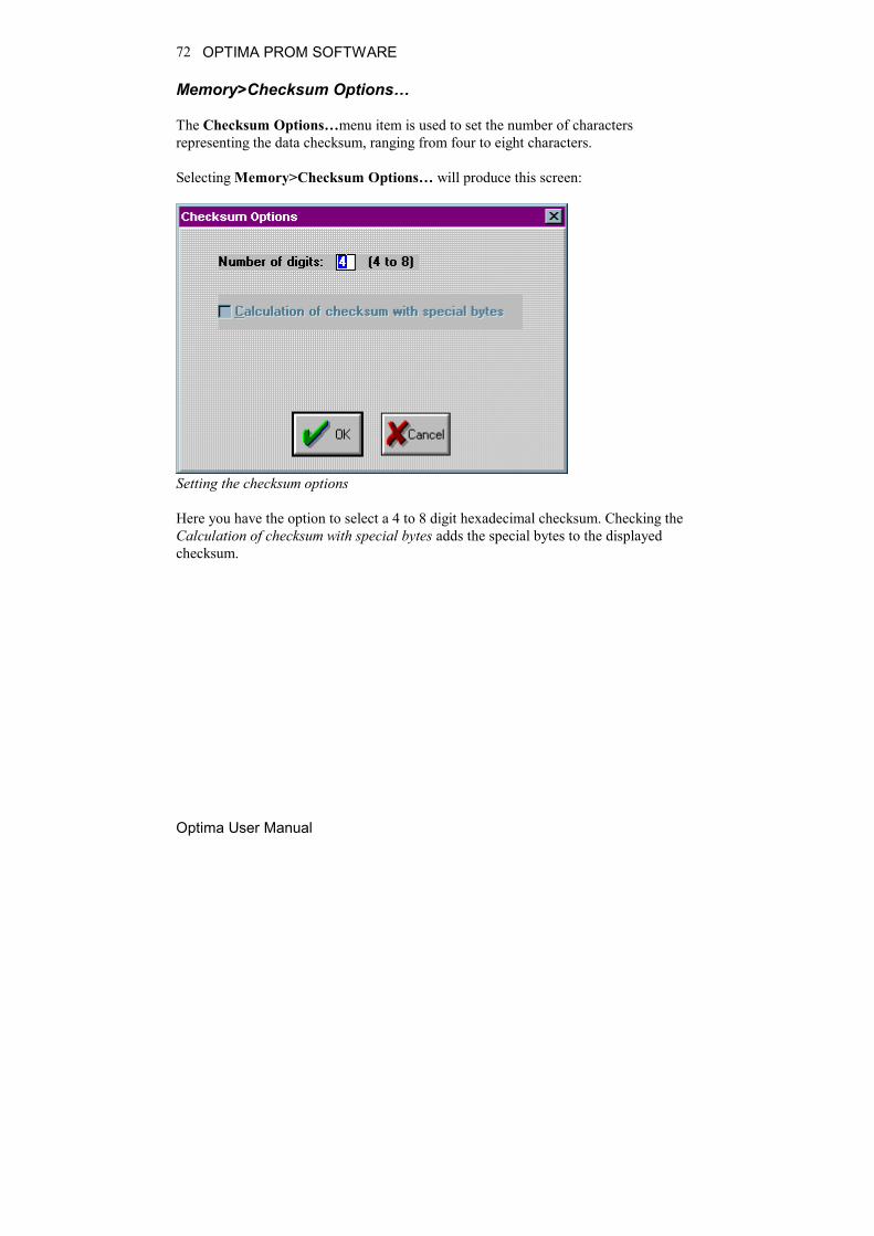
Memory>Checksum Options…
The Checksum Options…menu item is used to set the number of charactersrepresenting the data checksum, ranging from four to eight characters.
Selecting Memory>Checksum Options… will produce this screen:
Setting the checksum options
Here you have the option to select a 4 to 8 digit hexadecimal checksum. Checking theCalculation of checksum with special bytes adds the special bytes to the displayedchecksum.

OPTIMA PROM SOFTWARE
Optima User Manual
73
Memory>Special Device Functions…
The Special Device Functions…menu item is used to set features unique to thedevices under test. This feature is enabled only for devices with special features.Additionally, these features vary from device to device.
Setting special device functions

OPTIMA PROM SOFTWARE
Optima User Manual
74
Memory>Device Serialization Options…
The Device Serialization Options…allows you to assign unique electronic serialnumbers to each device being programmed. When serializing devices, the serialnumber is automatically incremented for the next device each time the Optimasoftware completes a programming operation. When serializing with Multisyteprogrammers (Dual, Quad, and Octal) in gang mode, sequential serial numbers areautomatically generated for devices inserted into adjacent TOPs.
Note: Serialization is only supported with single-socket TOPs, suchas the TOP48, TOP84PLC, and other similar TOPs. It is notsupported on the TOP432or Flash TOP.
To set up this feature, refer to the figures below and perform the following process:
1. Select Memory > Device Serialization Options… The following screen willappear:
Selecting the serial number file 2. Choose the path and serial number file you would like to use, or if creating a new
serial number file, type in the desired name of the file in the File name field. Forclarity, use DOS standard 8.3 file names. The default file extension for serialnumber files is *.sn, but can be anything you like. To locate files with extensions
OPTIMA PROM SOFTWARE
Optima User Manual
75
other than *.sn, select All (*.*) from the List files of type pull-down menu in thelower left of the window.
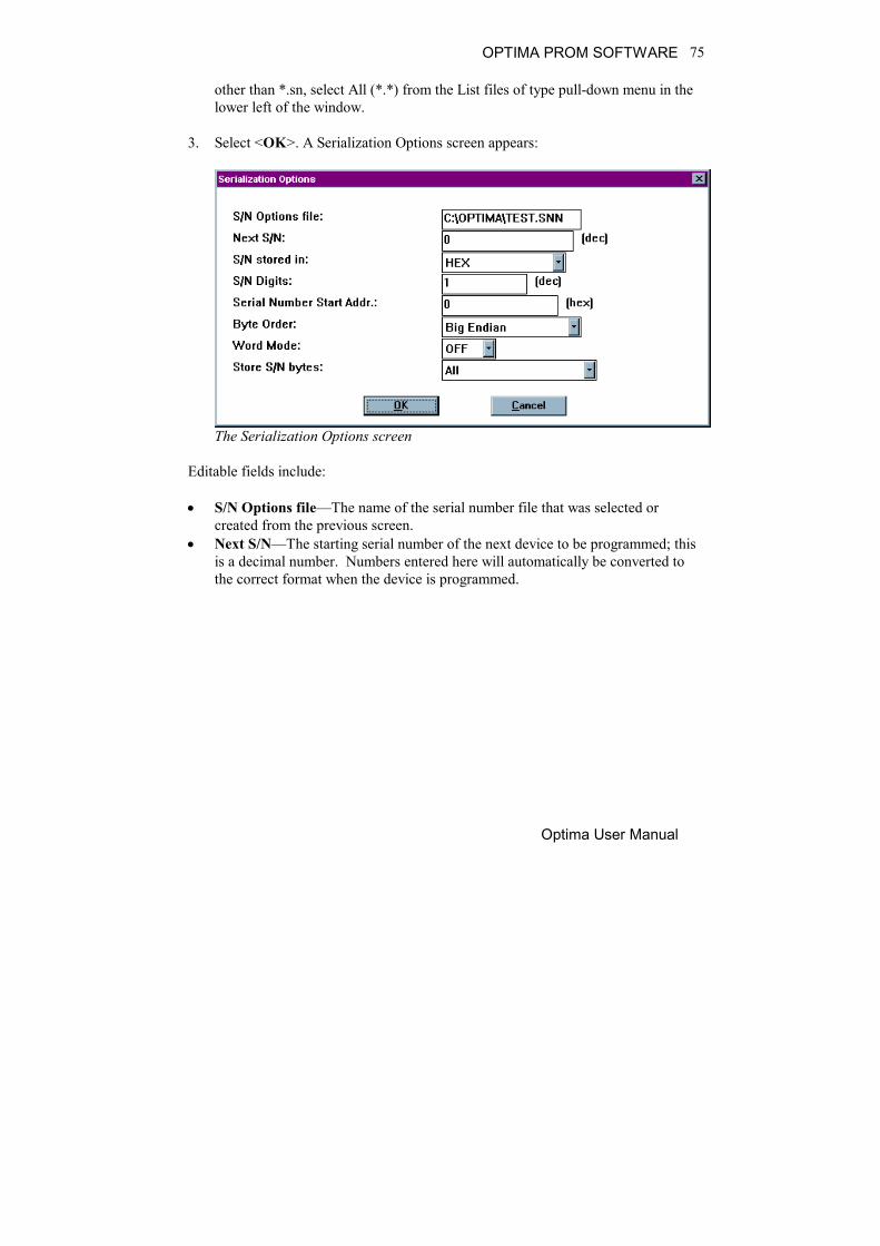
3. Select <OK>. A Serialization Options screen appears:
The Serialization Options screen
Editable fields include:
S/N Options file—The name of the serial number file that was selected orcreated from the previous screen.
Next S/N—The starting serial number of the next device to be programmed; thisis a decimal number. Numbers entered here will automatically be converted tothe correct format when the device is programmed.

OPTIMA PROM SOFTWARE
Optima User Manual
76
S/N stored in—Selects the format that the serial number data will be written tothe device; choices are HEX (each digit from 0h to Fh), ASCII (each digit from30h to 39h), and BCD (00002 to 10012).
Selecting the format to store serial number data
S/N Digits—Selects the number of characters, in decimal, used for the serialnumber format. The maximum number of characters is:
8 for S/Ns stored in HEX (FFFFFFFFh); S/Ns 0 through 4,294,967,295 9 for S/Ns stored in ASCII (393939393939393939h); S/Ns 0 through
999,999,999 8 for S/Ns stored in BCD (99999999h); S/Ns 0 through 2,576,980,377
Note: The S/N Digits value indicates the number of hex charactersthat are permitted to exist as a serial number in the memoryarray. The exception to this rule is the ASCII format, inwhich the number represents hex bytes. While this appearscomplicated, as long as the serial number limits are notexceeded, no errors will occur.
Serial Number Start Addr.—The hexadecimal address in the memory arraywhere the first byte of the serial number will be placed. All characters of theserial number must fit within the memory array of the device or serialization willnot take place.

OPTIMA PROM SOFTWARE
Optima User Manual
77
Byte Order—Used to select the order that the serial number data is placed in thedevice as related to the data file; choices include Big Endian (Hi byte/Lo byte—Motorola) and Little Endian (Lo byte/Hi byte—Intel).
Word Mode—Set when a serial number byte is to extend to the word width ofthe device. If word mode is set to:
Off—The default byte width of 8 bits is used. On—One byte of the serial number data will occupy the width of the
data path. If the data width of the device is 16 bits wide, then one byteof the serial number will also be 16 bits wide. For unique devices, suchas some Microchip Technology devices, the word width may be 12 or 14bits.
Selecting the byte order of a data file

OPTIMA PROM SOFTWARE
Optima User Manual
78
Store S/N bytes—This setting specifies which bytes are written to the memoryarray and in which order. The selections are:
All—All bytes of the serial number are written to the memory array. Even—Only the even bytes of the serial number are written. If this
option is selected, then the number of serial number digits (selected inS/N Digits) must be even (2, 4, 6, or 8).
Odd—Only the odd bytes of the serial number are written. If this optionis selected, then the number of serial number digits must be even (2, 4, 6,or 8).
0 of four, 1 of four, 2 of four, 3 of four—Only bytes in thecorresponding byte position in the serial number are written. Forexample, if a HEX serial number of 00BC614Eh is generated, when 1 offour is selected, BCh (byte #1 of four bytes total) is written to thedesignated start address. The largest hexadecimal serial number allowedis FFFFFFFFh, or 4,294,967,29510. The largest BCD serial numberallowed is 99999999h, or 2,576,980,37710
Selecting the method of storing serial number bytes
Note: The X of four mode works only with hexadecimal and BCDserial number types as selected in the S/N stored in field.

OPTIMA PROM SOFTWARE
Optima User Manual
79
Selecting ASCII as a serial number value type will return anerror.
The Device Menu The third menu on the Main Programming screen is the Device menu. This menuprovides you with basic operational commands as shown in the figure below:
The Device menu The Program, Read, Blank Check, and Verify commands can be initiated from thismenu.

OPTIMA PROM SOFTWARE
Optima User Manual
80
Device>Program Selecting Device>Program produces the following dialogue:
Starting the Program routine Selecting <Yes> begins the programming operation; <No> stops the programmingoperation.

OPTIMA PROM SOFTWARE
Optima User Manual
81
Upon successful completion of the programming operation, PASS will appear in theStatus area indicating proper programming:
Programming operation has passed Any special information related to the programming operation will appear in theMessages text area at the bottom of the screen. The first process performed on the device during the Program operation is a check forblank state. If the device is EEPROM based, then an erase cycle will be executedautomatically. If it is not erased and is UV-erasable or is a one-time programmable(OTP) device, the Optima software will test to see if the pattern in memory can beover-programmed (that is, new data is programmed on top of the existing pattern inthe device). If over-programming is possible, then you will be asked Skip blank check:Yes/No. If you select <YES>, then the device will be over-programmed. If you select<No>, you will receive a “Device not blank” error message, and the Programoperation will stop.

OPTIMA PROM SOFTWARE
Optima User Manual
82
After the automatic blank check is completed, the device will then be programmedusing the algorithm defined by the manufacturer. Intelligent programming is used tokeep programming time to a minimum. The intelligent programming algorithm isselected automatically when the device type is selected. After programming, the device will be verified to confirm proper programming. Ifthere are any errors in verification, you can create a detailed report of the errors on thescreen (see Device>Verify section). If the device vendor specifies it, verification willbe done at the Vcc high and Vcc low levels in accordance with manufacturer’sspecifications. If the device is improperly inserted into the socket, the device is defective, or theprogramming TOP is faulty, then a continuity message appears:
Continuity error A yellow light on the TOP itself, as well as a yellow light on the TOP icon on theMain Programming screen, identifies the socket with the continuity error. Thesoftware prompts you to <Display> the pin(s) in error, <Cancel> the operation,<Retry> the operation, or <Ignore> the error and continue.

OPTIMA PROM SOFTWARE
Optima User Manual
83
The Optima software contains a convenient tool for isolating the cause of a continuityfailure. Selecting the <Display> option presents you with a package diagramoutlining the pin(s) that are believed to be causing the failure:
Pinmap showing continuity failures; pins displayed here in gray are not makingproper contact. On user interface, pins not making proper contact are displayed inred.

OPTIMA PROM SOFTWARE
Optima User Manual
84
Device>Read Selecting Device>Read retrieves the data contents of the device in the socket andreads them into memory. While the read operation is in progress, the status windowdisplays the term ACTIVE and shows the percentage of completion. When the readoperation is complete, a PASS or FAIL message indicates its success or failure. Usingthe <Read Device> button in the Device Action section yields the same results. Anyadditional information related to this read operation is also displayed in the Messagessection of the screen:
Successful completion of a READ operation
When using a Multisyte programmer, insert the device in the left-most TOP for theread operation.

OPTIMA PROM SOFTWARE
Optima User Manual
85
Device>Blank Check The Blank Check feature may be enabled or disabled depending on the deviceselected. If the feature is enabled, selecting Device>Blank Check lets you determineif the device under test is truly empty. If the blank check passes, the device is trulyempty. Otherwise, some of the device locations may have data in them. UV erasable devices must be erased under ultraviolet light in accordance with themanufacturer’s instructions before programming.
Note: Not all UV erasable devices are guaranteed to arrive blankfrom the manufacturer. If they are not blank, simply erasethem according to the manufacturer’s guidelines for thedevice under test.
The Blank Check function is performed prior to all programming functions. You mayalso initiate the Blank Check operation from the <Blank Check> button in the DeviceAction section of the screen.

OPTIMA PROM SOFTWARE
Optima User Manual
86
Device>Verify Devices may also be verified with known good data by selecting Device>Verify Touse this function, you must first read the device’s data into the programmer/softwareRAM. The data can be read two different ways: Select Device>Read to read a master device into programmer/software RAM. Select File>Load to load a data file into programmer/software RAM.
Once the data to be verified has been successfully loaded into programmer/softwareRAM, insert the device into the programmer socket. Select Device>Verify, or clickthe <Verify> button in the Device Action section of the screen to initiate the Verifyaction. During the Verify action, a byte-by-byte comparison is performed between thedata in RAM and the device in the socket. When the Verify action is complete,PASS/FAIL results will be displayed in the Status section of the screen, as well as inthe Messages section
Device Verify Pass message

OPTIMA PROM SOFTWARE
Optima User Manual
87
If you get an error message, the following screen will identify the address from RAMand PROM and data information where errors occurred:
Device verification errors are displayed with location information

OPTIMA PROM SOFTWARE
Optima User Manual
88
The Select Device Menu
The fourth menu on the Main Programming screen is the Select Device menu.
The Select Device menu

OPTIMA PROM SOFTWARE
Optima User Manual
89
The Select Device menu allows you to select the type of device you wish to program.When selected, the Change Device screen appears:
Selecting the device to be programmed
Select the vendor, family and device to be processed from the list and click <OK>.
The devices listed are those that are supported by the TOP that has been installed. Ifyou do not find the device on the list, follow these steps:
1. Turn off power to the programmer2. Close the software3. Remove the TOP4. Install a TOP that supports the device you wish to program

OPTIMA PROM SOFTWARE
Optima User Manual
90
If you see TOP! next to the vendor name, no device manufactured by that vendor issupported by the TOP you have installed. For example, the TOP48 does not supportany Actel devices, as shown here:
Vendor not supported by this TOP

OPTIMA PROM SOFTWARE
Optima User Manual
91
If you see TOP! beside the family name, devices in that family are not supported bythe TOP you have installed. For example, the TOP48 does not support the family ofMB 7 devices. By reading the Sxxx number beside the device listed, you candetermine which TOP does support the device you wish to program:
MB 7 device family not supported by this TOP

OPTIMA PROM SOFTWARE
Optima User Manual
92
If you see Sxxx beside the device name, that device is not supported by the TOP youhave installed. For example, the TOP48 does not support Hitachi HD647325, asshown here:
Device not supported by this TOP

OPTIMA PROM SOFTWARE
Optima User Manual
93
If you see SMP beside the device name, your current level of support does not includethis device and needs to be updated. To update your level of support, see theSOFTWARE MAINTENANCE PLAN section of the Optima User Manual.
Level of support does not include this device

OPTIMA PROM SOFTWARE
Optima User Manual
94
The Options Menu
The fifth menu on the Main Programming screen is the Options menu.
The Options menu
Many programming operations are adjustable through the Options menu. Amongthese are verify operation parameters, blank check, electronic erase, continuity checks,electronic ID checks, specific algorithm parameters, checksum options, and variousspecial functions.
Note: Many of the options displayed in the Options menu aredevice specific and may not be available for allprogramming operations. In the example above, a UVerasable device has been selected, and the EErase menu itemis not available.

OPTIMA PROM SOFTWARE
Optima User Manual
95
The following items can be found in the Options menu:
Verify Off, Verify Normal, Verify High/Low—Used to set the method ofdevice data verification after programming.
Verify Off provides no verification of the device after programming Verify Normal provides a single-pass verify at nominal VCC for the
device after programming Verify High/Low provides a two-pass verify; first at device-rated low
VCC, and second at device-rated high VCC
Blank Check—Adds a Blank Check operation to the programming operation. Ifa device is not blank during the programming operation, a message will appearnotifying you that the device in use is not blank. If you choose to continue, thedevice will be over-programmed. This option will not be available withelectrically-erasable devices.
EErase—Adds an Electrical Erase operation to the programming operation if thefunction is supported with the selected device. This option will not be availablefor UV erasable devices and one-time-programmable (OTP) devices.
Continuity Check—If enabled, checks for proper device continuity before aprogramming operation. Continuity errors will present the standard continuitywarning message and will allow you to display the pins in question. This optionshould not be turned off unless there is a known reason to do so.
ID Check—Allows for checking for the manufacturer’s electronic ID prior toprogramming. As a safety-net style of operation, many manufacturers assigntheir devices a unique identification number. Occasionally, when manufacturerschange a physical or electrical specification for a device, they may also changethe electronic ID of that device.
For example, if a modification in die size also requires a change in theprogramming algorithm to increase performance or compatibility, themanufacturer may change the electronic ID. When electronic ID is turned ON,this change can be detected, and the device manufacturer can be contacted toverify that a change has taken place. If the change is significant, a new algorithmmay need to be developed to support this new device configuration.

OPTIMA PROM SOFTWARE
Optima User Manual
96
Note: If the device ID is different from that which the algorithmexpects, the programmer software may not allow you tocontinue until the discrepancy is corrected.
If the device is determined to require no algorithm changes, electronic ID may beturned OFF until such time that the algorithm may be updated to incorporate thenew electronic ID. Additionally, ID Check may be set to AUTO to automaticallydetect the electronic ID of those devices supporting this option.
Algorithm Options—Used to change specific programming parameters withinthe algorithm.

OPTIMA PROM SOFTWARE
Optima User Manual
97
The Utilities Menu
The sixth menu on the Main Programming screen is the Utilities menu.
The Utilities Menu
You can create a complete list of devices supported by the Optima familyprogrammers by using the Utilities menu.

OPTIMA PROM SOFTWARE
Optima User Manual
98
Utilities>Create Devicelist
To create a device list, select Utilities>Create Devicelist. The following screenappears:
Attention screen
Click <Yes> to continue.
A file titled “dev_prm.txt” is then created in your Optima directory. It lists all theprogrammable memory and microcontroller devices supported for the installedversion of Optima software. The “dev_prm.txt” file is tab delimited and can beimported into an Excel spreadsheet. Once imported, use Excel to filter the file tocreate a device list that meets your specific needs:
Excel spreadsheet device list (portion)

OPTIMA PROM SOFTWARE
Optima User Manual
99
The Help Menu
The seventh menu on the Main Programming screen is the Help menu.
The Help menu
The Help menu provides assistance with commonly used features and functions of theOptima software. This menu function may not be available in early versions of theOptima software. To ensure that you are using the latest revision of programmersoftware, download the programmer updates from Data I/O’s web site.

OPTIMA PROM SOFTWARE
Optima User Manual
100

OPTIMA PAL SOFTWARE
Optima User Manual
101
OPTIMA PAL SOFTWARE
This section of the Optima User Manual provides detailed descriptions of the OptimaPAL software used for programming logic devices. If you wish to get startedprogramming logic devices quickly, go to the QUICK START section of the OptimaUser Manual.
Main Programming Screen
Once the device has been selected, the Main Programming screen for the Optima PALsoftware will appear:
PAL software Main Programming screen

OPTIMA PAL SOFTWARE
Optima User Manual
102
The Main Programming screen is divided into these areas:
File—contains information regarding the checksum of the data currently in RAMand the usable address range of the device
Device—contains information related to the device to be processed. The
Devicecode: field contains a unique identification code for the device selected.This code is used by the optional TaskLink Windows software.
OPTIMA Xx/XX—contains information about the PAL software version, the
TOPs installed on the programmer base, and the programming mode (single,gang, or swap).
Status—provides the status of the last device programmed(PASS/FAIL/CHECK), the total number of devices to be processed (this field iseditable), and the number of devices remaining to be processed.
Device Action—provides quick access to the most commonly used operations.
There are buttons for Program, Read Device, Blank Check, Verify, Secure Deviceand Test operations.
Additional information—contains any additional information that may berequired to process the selected devices, such as a specialized adapter, etc.
Messages—contains any additional messages that describe various conditions
related to the processing of the selected device. Messages that may appearinclude references to specialized adapters, settings that have been changed totheir non-default conditions, and others.
The area titled Optima Xx/XX contains several controls that determine the site(s) tobe used for programming, the TOPs installed on the site(s), and the programmingmodes of operation. This section contains a virtual layout of the programmer in use.If the programmer is an Optima Light, then one programmer site is shown, and theTOP that has been installed is shown. If the programmer is an Octal, then eight sitesare displayed (arranged numerically from left to right, top to bottom, with Site #1 atthe upper left and Site #8 at the lower right), as well as indicators of the TOPsinstalled on each site. If no TOPs are installed on one or more of the sites, those siteswill be displayed as NO TOP.

OPTIMA PAL SOFTWARE
Optima User Manual
103
The area titled Device Action contains several controls that provide quick access tothe most commonly used programming actions, such as Program, Read Device,Blank Check, Verify, Secure Device, and Test. These controls function identicallyto the controls found in the Device menu, and are conveniently located on the MainProgramming screen for quick access.

OPTIMA PAL SOFTWARE
Optima User Manual
104
The File Menu
The first menu on the Main Programming screen is the File menu. The File menu hastwo primary functions: loading data into RAM, and saving data from RAM.Additionally, the PAL software can be terminated from this menu using the Exitfunction.
The File menu

OPTIMA PAL SOFTWARE
Optima User Manual
105
File>Load
Selecting File > Load will produce the File Open dialog screen:
The File Open dialogue
The File Open dialogue allows the use of several different data formats including:
JEDEC standard (*.jed) Altera POF format (*.pof) Altera JAM format (*.jam)
Navigate the computer or network for the required data file, and select the <OK>button. Once the file is loaded, the device may be programmed.

OPTIMA PAL SOFTWARE
Optima User Manual
106
File>Save As
There is also an option for saving the data in RAM as a data file. This can be helpfulwhen you have a master device but no data file, and you would like to create one. TheSave As dialogue allows the generation of data files as shown below:
The Save-As dialogue
You may save data files in standard JEDEC (*.jed) format only. Select a path andfilename for your file, then select <OK> to save it to the designated location.

OPTIMA PAL SOFTWARE
Optima User Manual
107
The Memory Menu
The second menu on the Main Programming screen is the Memory menu. TheMemory menu provides you with a method to view and/or edit the contents ofmemory at any time before or after the programming operation:
The Memory menu

OPTIMA PAL SOFTWARE
Optima User Manual
108
Memory>Edit
Selecting Memory>Edit from the Memory menu will produce the following screen:
The Edit menu
The editor screen allows you to view the fusemap of the logic device under test, andalso allows you to edit the fusemap manually if necessary. As can be seen in thefigure above, a portion of the addressable fuse locations is displayed. If there is a “–”symbol in any location, that fuse has been blown, while the “X” symbol indicates thatthe fuse is still intact. Some of the additional controls on the screen include:
All to ‘–’—Blows all fuses in the device All to ‘X’—Connects all fuses in the device Set Line to ‘–’—Blows all fuses in the line that has been selected by the mouse
cursor; indicated by the highlighted line Set Line to ‘X’—Connects all fuses in the line that has been selected by the
mouse cursor; indicated by the highlighted line Home—Sends the cursor back to the beginning fuse location of the device End—Sends the cursor to the last fuse location of the device

OPTIMA PAL SOFTWARE
Optima User Manual
109
Page (upper button)—Moves the cursor up one page of data each time thebutton is pressed
Page (lower button)—Moves the cursor down one page of data each time thebutton is pressed
Up—Moves the cursor up one line of data each time the button is pressed Down—Moves the cursor down one line of data each time the button is pressed
An additional function that can be used from the editor screen is a simple fuselocation indicator. To use this indicator, simply place the mouse cursor over thelocation in question, right-click the location with the mouse, and a window will appearwith the fuse location:
Right-clicking the edit screen will provide the fuse location under the cursor

OPTIMA PAL SOFTWARE
Optima User Manual
110
The Device Menu
The third menu on the Main Programming screen is the Device menu. This menu isused to select the programmer operation for the device inserted:
The Device menu
Device> Program
This selection initiates the programming operation using the data that is stored in thememory buffer. The device type selected must match the physical device in thesocket.
The device will first be checked for blank state or electrically erased. If the device iselectrically erasable, then an erase cycle will be automatically executed. If it is noterased—and is UV-erasable or is a one-time-programmable (OTP) device—the PAL

OPTIMA PAL SOFTWARE
Optima User Manual
111
software will test to see if the pattern in memory can be over-programmed, whereadditional data is programmed on top of the existing pattern in the device. If over-programming is possible, then you will be prompted to “Skip blank check.” If youselect <Yes>, then the device will be over-programmed. If you select <No>, you willreceive a “Device not blank” error, and programming will stop.
After the blank check or erase operation is complete, the device will be programmedusing the algorithm defined by the manufacturer.
After programming, the device will be verified to confirm proper programming. Ifthere are any errors in verification, you can create a detailed report of the errors on thescreen (see Device>Verify later in this menu description). If the device vendorspecifies it, verification will be done at the VCC high and VCC low levels in accordancewith manufacturer’s specifications. After verification, if the security fuse commandwas included in the JEDEC file, the security fuse of the device will be set (seeDevice>Secure later in this menu description). If test vectors were included in theJEDEC file, they will then be used to exercise the device (see Device>Test later inthis menu description).
You are informed of the sequence of steps in the programming operation by messageson the screen. PASS/FAIL messages are provided in the status box indicatingprogramming status. A cycle counter is provided below the PASS/FAIL message areadisplaying the number of devices programmed with the same content.

OPTIMA PAL SOFTWARE
Optima User Manual
112
Device>Read
This selection reads the contents of the device inserted in the socket and stores it inRAM memory. After the data has been read into memory, the device type may bechanged to a compatible device without altering any data stored.
Successful completion of a READ operation
When using a Multisyte programmer, insert the device in the left-most TOP for theread operation.
Note: Not all logic devices are capable of having their fusemapsread by a device programmer. For those that are readable,if their fusemaps have been placed in a SECURE condition,the programmer will not be permitted to read the fusemap,or the data will be encrypted such that each read operationwill return different results, perhaps even blank. This is asecurity feature on a number of logic devices that ensures

OPTIMA PAL SOFTWARE
Optima User Manual
113
the data on the device cannot be read by unauthorizedpersonnel.
Device>Blank Check
This selection verifies that the non-electrically erasable device in the socket is in theerased condition. The device in the socket is read and the contents compared to theexpected “erased” condition. The device type selected must match the physicaldevice inserted in the socket.
Electrically-erasable devices do not require a blank check operation. These devicesare automatically erased as part of the programming cycle.
Note: Blank Check operation is automatically performed during theProgram operation.
Device>Verify
This selection verifies the fusemap against the data file to ensure they match; anyverify failures will produce the following error:
Verify failure will prompt you to display a detailed report

OPTIMA PAL SOFTWARE
Optima User Manual
114
If you select <YES>, then the following screen appears:
Device error map following a verify failure
On the screen above, there are indications of the device locations and the failuresencountered. Blank spaces indicate locations where the data matched. Any spacewith either a “–” symbol or an “X” symbol is an error, where the symbols indicate thedata that was expected in that location (“–” = blown fuse, “X” = connected fuse). The<More> button provides more failure data if it exceeds the capacity of the window. Ifa device has been secured, the Verify operation will not function correctly.
Device>Secure
This selection manually sets the security feature of the device inserted in the socket.Many logic devices have optional security fuses that can be programmed after allother fuses have been programmed. These final fuses prohibit reading (and

OPTIMA PAL SOFTWARE
Optima User Manual
115
verification) of the device. This means that the pattern set into the fuses of the deviceis no longer readable by personnel who are not authorized to view the data pattern.
To manually secure the device, select Device>Secure. This must be the last step inany programming sequence since the programmer expects to able to verify (read) adevice after programming.
In automatic mode (set with the Auto Security selection in the Options menu), thesecurity fuse(s) will be set during each programming cycle, after verifying and beforevector testing. If the JEDEC file contains the security fuse command (G1*), the AutoSecurity mode is automatically enabled, and the Auto Security feature will bechecked in the Options menu.
The PAL software first programs the security fuse, then reads the array to verify thatthe data no longer matches the array. The PASS message will only be displayed if thearray data is no longer readable.
Some devices disable preload if the security fuse is set. For these devices, OptimaPAL will run the test vector program before setting the security fuse during theprogramming routine.
Some devices have a mode to read out the security fuse bit. Optima PAL can read thisbit and will indicate that the security bit is set. However, it will then perform adouble-check of the array contents to assure protection.
Device>Test
This selection performs vector testing of the device after programming. If a JEDECfile with test vectors has been read into memory, then the device in the socket can betested for conformance with these test sequences with this command. This test willalso be invoked after the Verify operation in a programming cycle if test vectors are inmemory.
Note: If no test vectors are appended to the JEDEC file, this optionis not enabled.
The Test operation has three passes for each vector. Pass 1 sets up all input pins.Any 0, 1, or X levels are presented to the device. All device outputs are set to readmode. Optima PAL has a special method for handling the “X” (don’t care) level,which is incompletely defined in the JEDEC specification and is often a cause ofvector test failures in other systems.

OPTIMA PAL SOFTWARE
Optima User Manual
116
Pass 2 applies any clocks to the device. The vector is scanned from highest pin tolowest pin, and the clocks are output in that order. If a multiple click device requires acontrolled sequence of clocks, then there should be a separate vector for each clock.It is impossible for a universal programmer like the Optima programmer to generatesimultaneous clocks on two pins. There will always be a time spacing betweenmultiple clocks in a test vector. Note that the “C” clock is normally low, and the “K”clock is normally high.
Pass 2 also executes the preload function if a P or B vector is found. A P or B in pin1of the vector indicates preload. Note that entering and leaving preload mode cangenerate transient logic levels that can have other effects in a PAL design.
Pass 3 verifies the outputs of the devices against the test vector. If there are no errors,the next vector is processed. If there are any errors, the good and bad data will bedisplayed on the screen, and testing will stop unless continued by you.
Pins defined as “X” in the vectors are set as inputs to “0” unless the pin is determinedto be an unused output, in which case it is floated. High impedance outputs are testedfor incorrect “0” conditions, but not for low impedance “1” conditions. Testsimulation can also be used to verify a device after the security fuse has beenprogrammed (note that AMD PALCE-family of devices disables preload whensecurity is set).

OPTIMA PAL SOFTWARE
Optima User Manual
117
The Select Device Menu
The fourth menu on the Main Programming screen is the Select Device menu.
The Select Device menu

OPTIMA PAL SOFTWARE
Optima User Manual
118
The Select Device menu allows you to select the type of device you wish to program.When selected, the Change Device screen appears:
Selecting the device to be programmed
In the example above, the Optima software has recognized the TOP48 is in use. Thedevices listed are those that are supported by the TOP that has been installed. If thedevice is not found on the list, then it is probably not supported by that TOP. Be sureto check all of the Family classifications for the device in case the part number is in adifferent location than expected. The Family categories are presorted in a number offashions to make searching for the device more efficient.
Because the information in the device selection dialogue is the exact same data that isused to create the device list, the device menu name will be exactly as it is noted in thedevice list. If you do not have a current device list, see Utilities>Creating aDevicelist.

OPTIMA PAL SOFTWARE
Optima User Manual
119
The Options Menu
The fifth menu on the Main Programming screen is the Options menu.
The Options menu
Many programming operations are adjustable through the Options menu. Amongthese are Continuity Check, Blank Check, verification parameters, AutomaticSecurity, Vectortest, and specific algorithm parameters.
Many of the options displayed in the Options menu are device-specific and may notbe available for all programming operations. For example, a UV erasable device maynot have the Blank Check menu item available to the user.

OPTIMA PAL SOFTWARE
Optima User Manual
120
Options>Continuity Check
If enabled, this selection checks for proper device alignment in the socket before aprogramming operation. Alignment errors will present the standard continuitywarning message and allow you to <Display> the pins in question:
Displaying the device pin map following a continuity failure
Note: The Continuity Check option should always be enabled unlessthere is a known reason to turn it off.
Options>Blank Check
This selection adds a Blank Check operation to the programming operation if thedevice requires blank check. If a device is not blank during the programmingoperation, a message will appear notifying you that the device in use is not blank. Ifyou choose to continue, the device will be over-programmed.

OPTIMA PAL SOFTWARE
Optima User Manual
121
This option is not available with electrically-erasable devices.

OPTIMA PAL SOFTWARE
Optima User Manual
122
Options>Verify Options
This selection is used to set the methods of device data verification afterprogramming:
Verification options in the Options menu
The following device verification options are available:
Verify Off provides no verification of the device after programming Verify Normal provides a single-pass verify at nominal VCC for the device after
programming Verify Low provides a single-pass verify at device-rated low VCC
Verify High provides a single-pass verify at device-rated high VCC
Verify Low and High provides a two-pass verify; once at device-rated low VCC,and a second at device-rated high VCC

OPTIMA PAL SOFTWARE
Optima User Manual
123
Options>Auto Security
When selected, the security fuse(s) will be set during each programming cycle, afterverifying and before vector testing. If the JEDEC file contains the security fusecommand (G1*), the Auto Security mode is automatically enabled, and the AutoSecurity feature will be checked regardless of initial condition.
Options>Vectortest
This selection is used to select the vector testing methods of the device afterprogramming. If a JEDEC file with test vectors has been read into memory, then thedevice in the socket can be tested for conformance with these test sequences with thiscommand:
Vector testing options in the Options menu

OPTIMA PAL SOFTWARE
Optima User Manual
124
The following vector test options are available:
Off provides no vector testing of the device after programming Normal provides a single-pass vector test at nominal VCC for the device after
programming Low provides a single-pass vector test at device-rated low VCC
High provides a single-pass vector test at device-rated high VCC
Low and High provides a two-pass vector test; once at device-rated low VCC,and a second at device-rated high VCC
Options>Algorithm Options…
This selection provides device-specific information about the device to beprogrammed:
Algorithm options screen
Certain PAL devices can store an electronic signature that contains user-defined datasuch as ID codes, revision numbers, or inventory numbers.
The electronic signature is always available to the user independent of the state of thesecurity bit.

OPTIMA PAL SOFTWARE
Optima User Manual
125
The Utilities Menu
The sixth menu on the Main Programming screen is the Utilities menu:
The Utilities menu
You can create a complete list of devices supported by the Optima Familyprogrammers by using the Utilities menu.

OPTIMA PAL SOFTWARE
Optima User Manual
126
Utilities>Create Devicelist
To create a device list, select Utilities>Create Devicelist. The following screenappears:
Attention screen
Click <Yes> to continue.
A file titled “dev_pal.txt” is then created in your Optima directory. It lists all theprogrammable logic devices supported for the installed version of Optima software.The “dev_pal.txt” file is tab delimited and can be imported into an Excel spreadsheet.Once imported, use Excel to filter the file to create a device list that meets yourspecific needs.
Excel spreadsheet device list (portion)

OPTIMA PAL SOFTWARE
Optima User Manual
127
The Help Menu
The seventh menu on the Main Programmer screen is the Help menu:
The Help menu
The information available in the Help menu provides assistance with commonly usedfeatures and functions of the Optima PAL software.

SINGLE, GANG, AND SWAP PROGRAMMING
Optima User Manual
128
SINGLE, GANG, AND SWAP PROGRAMMING
Optima programmers allow you to program devices one at a time or several at a time.This flexibility greatly increases programming efficiency.
In single programming mode, one device at a time is programmed. Singleprogramming can be done on either Singlestye (Optima, Optima Light, or Plus 48) orMultisyte (Dual, Quad, or Octal) programmers, using any of the optional TOPs.
In gang programming mode, multiple devices can be programmed simultaneously,with the same data programmed into all devices. Up to eight devices can beprogrammed using a single site TOP, and up to 32 devices can be programmed usingthe FLASH TOP or TOP432.For gang programming, you need two or more identicalTOPs installed on your Multisyte programmer.
In swap programming mode, up to eight devices can be programmed in alternate (orswap) cycles, with the same data programmed into all devices. For swapprogramming, you need two or more identical TOPs installed on your Multisyteprogrammer.

SINGLE, GANG, AND SWAP PROGRAMMING
Optima User Manual
129
Processing Devices in the Single Programming Mode
In the diagram below, the programmer in use is a Quad, with four TOPs installed:
A Quad programmer with two TOP48s, a TOP432, and a TOP84PLC installed
A Multisyte programmer (Dual, Quad, or Octal) is quite flexible as it allows severaldifferent styles of TOPs to be installed simultaneously. While different TOPs stylescannot be used simultaneously to program different devices, each TOP can, however,be selected directly from the user interface when a different device style is required.
In the above configuration two TOP48s, a TOP432, and a TOP84PLC are installed.The TOP48 on Site #1 (left-most site) is selected, and the programmer is set tooperate in Single mode. As it is currently configured, the programmer will processdevices one at a time on the selected TOP. If you require the use of the another TOP,

SINGLE, GANG, AND SWAP PROGRAMMING
Optima User Manual
130
simply select the TOP on Site #2, #3 or #4 by clicking its icon with the mouse cursor.The newly selected site will be highlighted, indicating that it is the active site.
Note: If the programmer has different styles of TOPs installed,selecting a site with a different style of TOP will prompt youto select a new device. This is normal, as the software mustset up the programmer to process the different style ofdevice.

SINGLE, GANG, AND SWAP PROGRAMMING
Optima User Manual
131
Processing Devices in the Gang Programming Mode
Programming one device at a time can be time consuming. To expedite programmingdevices, gang programming can be used with the Multisyte line of programmers(Dual, Quad, and Octal):
A Quad programmer with four TOP48s installed
Here a Multisyte Quad is set to operate in gang mode. All four identical TOPs arehighlighted, indicating that they can be used simultaneously to program devices. It isnot necessary that all TOPs on the programmer are identical, but you do need at leasttwo identical TOPs for gang programming.

SINGLE, GANG, AND SWAP PROGRAMMING
Optima User Manual
132
To enter the gang-programming mode, perform the following:
1. Select the <single> button to enter the single programming mode.2. Select the TOP style to be used for programming in the gang mode by choosing
the appropriate TOP on any site.3. Select the <gang> button.
The LED to the left of the <gang> button will turn yellow, indicating it is waitingfor the next operation.
4. Select another identical TOP.The software will automatically select all of the TOPs of the same style installedon the programmer.
Note: The majority of devices are supported in gang more, but afew devices, particularly logic devices, may not besupported. Once you select gang programming, go to SelectDevice and make sure the device is supported in gangprogramming mode. You can also get this information fromCreate a Device List.
Note: If you decide to change TOPs while the Optima software isrunning, the programmer and software will not recognizethat the new TOP has been installed. To properly initializethe TOP, end the current session and restart the Optimasoftware. Removing and replacing TOPs while theprogrammer is turned on will not damage the programmeror the TOPs.
Once the gang programming mode is properly configured, all of the selected sites areused for simultaneous programming. When beginning the programming operation,devices can be inserted into all of the selected sockets for programming.

SINGLE, GANG, AND SWAP PROGRAMMING
Optima User Manual
133
Processing Devices in the Swap Programming Mode
In some cases the swap-programming mode further increases efficiency in aproduction environment. The swap mode is a modified gang mode, because it allowsyou to load, unload, and label devices on half of the TOPs on the programmer whilethe other half programs devices. As in gang programming, swap programmingrequires that you have at least two identical TOPs installed on your Multisyteprogrammer.
A Quad programmer with four TOP48s installed for swap programming
To enter the swap programming mode, perform the following:
1. Select the <swap> button.The LED beside it will turn yellow, indicating it is waiting for some user action.

SINGLE, GANG, AND SWAP PROGRAMMING
Optima User Manual
134
2. Select one of the installed TOPs on the programmer.The programmer will then select all of the TOPs that match the one chosen. Theindicator beside the <swap> button will turn green, indicating that theprogrammer is ready for operation in the swap mode.
3. In the Status section of the screen, enter the total number of devices to be
programmed in the text field labeled “total.”
Note: If the total number of devices to program is smaller than thenumber of sites on the programmer, then the swap mode willnot be activated. The purpose of this mode is to enhanceproductivity when processing a large number of devices.The swap mode is purposely deactivated when processingsmall quantities of devices.
4. From the Device Menu, select Program, or select <Program> to begin theprogramming operation.
5. A window will appear instructing you to insert devices into the sockets with
flashing indicators; insert the devices, then select <OK>. 6. While the first set of devices is being programmed, other sets may be prepared,
labeled, etc. 7. When the programming of the first set of devices is complete, the software will
instruct you to remove the programmed devices, insert the new devices, andselect <OK>; the removed devices can then be labeled, prepared, etc.

SINGLE, GANG, AND SWAP PROGRAMMING
Optima User Manual
135

SET PROGRAMMING ON THE TOP432
Optima User Manual
136
SET PROGRAMMING ON THE TOP432
The TOP432 consists of four 32-pin sockets, and is designed primarily for gangprogramming of memory devices, though it can also be used for set programming (upto four devices) of memory devices. A limited range of logic devices can also beprogrammed using the TOP432.
A Quad programmer with a TOP432 installed in Site #3
As with all TOPs, the TOP432 operates independently of other TOPs when differentTOP styles are installed on a Multisyte programmer. The only operating differencebetween the TOP432 and other TOPs is the number of devices supported by each.Otherwise all TOPs operate seamlessly on the programmer.
Like other TOPs, the TOP432 may be used in gang with other TOP432s on the sameprogrammer, thus providing a large throughput of devices. Using the TOP432 in amultiple-gang capacity is as simple as choosing the gang selection and choosing all

SET PROGRAMMING ON THE TOP432
Optima User Manual
137
TOP432s installed on the programmer. In this mode, all devices inserted into all ofthe TOPs will receive the same programming information.
The TOP432 is unique because it has both gang and set programming capabilities. Bydefault the TOP432 is in the gang programming mode, where each device isprogrammed with the same data. If you want to change to set programming, click onthe TOP432 icon. When the TOP432 icon appears, select SET-Mode programming.In set mode, you have the option of 8, 16 or 32 bit programming mode:
Gang/Set mode screen

SET PROGRAMMING ON THE TOP432
Optima User Manual
138
8 Bit Mode
Select the 8 Bit mode when a large data file needs to be programmed over multiplememory devices. In the example below the 64K file data is programmed into four16K memory devices. The first 16K (0000-3FFF) is programmed into socket 1, thesecond 16K (4000-7FFF) into socket 2, the third 16K (8000-BFFF) into socket 3, andthe fourth 16K (C000-FFFF) into socket 4.
The TOP432 creates the division of data automatically. The file is downloaded, the 8Bit mode is selected and the programming operation is started.
Device Size Socket 1 Socket 2 Socket 3 Socket 427C64 0, 1, 2… 2000, 2001… 4000, 4001… 6000, 6001…27C128 0, 1, 2… 4000, 4001… 8000, 8001… C000, C001…
16 Bit Mode
Select the 16 Bit mode when a 16 Bit data file needs to programmed into two 8 Bitdevices. In the example below the file data is a 16 Bit format. As the file data is readduring the programming operation, the TOP432 software places the low order bytes insockets 1 and 3. The high order bytes are placed in sockets 2 and 4.
Note: Often low order bytes are referred to as EVEN bytes and highorder bytes as ODD bytes.
The TOP432 creates the division of data automatically. The file is downloaded, the 16Bit mode is selected and the programming operation is started.
Device Size Socket 1 Socket 2 Socket 3 Socket 427C64 0, 2, 4… 1, 3, 5… 4000, 4002… 4001, 4003…27C128 0, 2, 4… 1, 3, 5… 8000, 8002… 8001, 8003…

SET PROGRAMMING ON THE TOP432
Optima User Manual
139
32 Bit Mode
Select the 32 Bit mode when a 32 Bit data file needs to programmed into four 8 Bitdevices. In the example below the file data is a 32 Bit format. As the file data is readduring the programming operation, the TOP432 software places low order data bytes(D0-D7) in socket 1. Data bytes (D8-D15) are placed in socket 2, data bytes (D16-D23) are placed in socket 3, and the high order bytes (D24-D310) are placed insocket 4.
The TOP432 creates the division of data automatically. The file is downloaded, the 32Bit mode is selected and the programming operation is started.
Device Size Socket 1 Socket 2 Socket 3 Socket 4any 0, 4, 8… 1, 5, 9… 2, 6, A… 3, 7, B…

SOFTWARE MAINTENANCE PLAN
Optima User Manual
140
SOFTWARE MAINTENANCE PLAN
The Software Maintenance Plan (SMP) helps ensure that you have the latest devicesupport available on your Optima programming system. When you purchase theSoftware Maintenance Plan, you are entitled to a full year of device support. You mayaccess this device support on the Data I/O web site or by contacting your Data I/OSales Representative for the latest software release on CD-ROM.
When programming devices, you may see the term “SMP” beside a device. The termindicates that the current level of your software does not support that device, and ifyou wish to proceed with programming, you will need to update your SoftwareMaintenance Plan.
Updating the Software Maintenance Plan
In order to update your Software Maintenance Plan, you will need to get an UpdateCode Number from your Data I/O Sales Representative. Prior to contacting your SalesRepresentative, locate and note the serial number for your programmer. The serialnumber can be located by either running the Self-Test and Calibration program andlooking under Serial #, or by checking for the serial number on the back of theprogrammer.

SOFTWARE MAINTENANCE PLAN
Optima User Manual
141
Once you have your Update Code Number, follow this procedure for updating yourSMP:
Select Optima TEST from the Start menu:
Starting Optima TEST with Window 95 or Windows 98

SOFTWARE MAINTENANCE PLAN
Optima User Manual
142
When selected, the following screen will appear:
Self-Test and Calibration screen
As prompted by the message, remove all devices or adapters from the sockets andpress any key to continue.

SOFTWARE MAINTENANCE PLAN
Optima User Manual
143
Once devices have been removed, pressing any key will begin a series of printer porttests to determine the computer’s ability to communicate with the programmer. Whenthe printer port tests are complete, you will be prompted to perform a Self Test.Selecting the <YES> button will begin the Self Test. When the Self Test is complete,the following screen is visible:
Self-Test and Calibration report
SMP expires after—The date that the current algorithm support expires. In thiscase, after B/99.

SOFTWARE MAINTENANCE PLAN
Optima User Manual
144
To update, select SMP Update from the menu bar. The following dialogue willappear:
Enter the new Update Code Number here, and then select <OK>.
To verify that the SMP has been updated, exit the Optima Calibration Utility using theQuit menu function, and re-start Optima TEST. Perform the steps as outlined above,and ensure that the new features have been installed.

SOFTWARE MAINTENANCE PLAN
Optima User Manual
145