optimal dg and capacitor allocation in distribution ...jestec.taylors.edu.my/vol 9 issue 5 october...
TRANSCRIPT

Journal of Engineering Science and Technology Vol. 9, No. 5 (2014) 641 - 656 © School of Engineering, Taylor’s University
641
OPTIMAL DG AND CAPACITOR ALLOCATION IN DISTRIBUTION SYSTEMS USING DICA
ARASH MAHARI1,*, AFSHIN MAHARI
2
1Faculty of Computer and Electrical Engineering, University of Tabriz, Tabriz, Iran 2Faculty of Engineering, Tabriz Branch, Azad University, Tabriz, Iran
*Corresponding Author: [email protected]
Abstract
In this paper, a method was presented based on Discrete Imperialistic Competition Algorithm (DICA) for optimal placement of Distributed
Generation (DG) and shunt capacitors. In this paper a new assimilation
mechanism in introduced for DICA. Developments of various technologies of
distributed generation and their cost-effectiveness have increased the use of
these resources. Shunt capacitors, as reactive power compensators, are also the equipment that inject reactive power to distribution network in order to
improve voltage profile release a part of the network capacity and also reduce
the losses. The objective function was defined based on the reduction of
active power losses. The performance of the proposed method tested on two,
33-bus and 69-bus IEEE standard systems. In spite of the objective function
defined based on active losses reduction, the results demonstrated that, voltage profile improved and reactive losses greatly reduced after optimal DG
and capacitor allocation.
Keywords: Distributed generation, Shunt capacitor, Optimal placement, Loss
reduction, DICA.
1. Introduction
Distribution networks have the highest rate of losses in power systems. Losses in
distribution networks not only cause electrical energy loss but also occupy
capacity of transformers and lines. Increasingly losses at peak times of load
consumption, increase the investment need in developing power plants and
transmission networks. One of the methods for reducing losses is to use
distributed generation resources and shunt compensation capacitors.
642 A. Mahari and A. Mahari
Journal of Engineering Science and Technology October 2014, Vol. 9(5)
Nomenclatures
Cap
iC
ith Capacitor size
Ii Current of ith line, A
NC Number of capacitors
NDG Number of DGs
DGP
Active powers of DGs
Pd Total active power demand of network loads
lossP
Active power losses of the network
sysP Active powers injected to the network by sub-transmission network
DG
ipf
ith DG power factor
CapQ
Injected reactive power of shunt capacitors
DGQ
Reactive powers of DGs
Qd Total reactive power demand of network loads
lossQ
Reactive power losses of the network
Qsys Reactive powers injected to the network by sub-transmission network
ri Resistance of ith line, ohm DG
iS i
th DG size
TCn Absolute total power of the nth empire
x Random variable
Shunt compensation capacitors are among the first equipment used in
electricity network, in order to improve voltage profile. The advantages of
capacitors include reducing active losses, reducing reactive losses, releasing
capacity of transformers and lines, improving power coefficient and maintaining
voltage within the specified allowed range. To take advantage of the mentioned
cases, the capacitors should be used in optimal locations with optimal sizes. For
optimal placement of a capacitor in electricity networks, different methods have
been presented [1-4].
With the development of technologies related to distributed generation
resources and utilizing inexpensive renewable energies, the penetration percent of
these energy generation resources in networks is increasing. Using distributed
generation resources provides many advantages for the network and its operator,
some of which include reducing active losses, reducing reactive losses,
postponing investment, increasing reliability, peak clipping, reducing cost of
electrical energy, improving voltage profile, etc. Optimal usage of the mentioned
advantages depends on placing and determining the optimal size of these
resources. Various methods have been proposed for optimal placement of
distributed generation resources with different objective functions [5-8].
Considering the advantages of using distributed generation and capacitors,
simultaneous use of these two provides multiple capabilities for electrical energy
distribution systems. Due to their different working bases, simultaneous optimal
placement of these two has different results from their independent placement [9].
Various methods have been proposed for optimal placement of DG and shunt
capacitors. [9] proposed two methods for optimal capacitor and DG placement.
The objective considered in [9] was voltage profile. A numerical method for the
Optimal DG and Capacitor Allocation in Distribution Systems Using DICA 643
Journal of Engineering Science and Technology October 2014, Vol. 9(5)
identification of the target voltage support zones is proposed by reducing the large
search space in [10] for optimal DG and capacitor placement. The optimal DG
and capacitor placement problem solved using Genetic Algorithm (GA) in [11].
In [12], a genetic algorithm (GA) is proposed for simultaneous power quality
improvement, optimal placement and sizing of fixed capacitor banks in radial
distribution networks with nonlinear loads and distributed generation (DG)
imposing voltage–current harmonics. In [13], simultaneous placement of
distributed generation (DG) and capacitor is considered in radial distribution
network with different load levels. The objective of the problem was voltage
stability index. Authors in [14], proposed a strategy for optimal capacitor and DG
placement in radial networks based for reactive and active losses reduction.
In this study, the basis of placement was reduction in losses of distribution
network, considering the technical and electrical constraints of the network. In this
regard, the Discrete Imperialistic Competition Algorithm was introduced. ICA is an
evolutionary computing algorithm and its process is based on social evolution and
colonial competitive between the imperialist in order to increase strength and
improve their positions [15]. ICA validity has been proved by testing on different
benchmark functions and optimization problems, in power systems [16-18].
In this paper, simulations were done on 33-bus and 69-bus IEEE standard
networks. First, optimal placement of capacitor and distributed generation was
separately done and then their simultaneous placement was performed at normal
and peak load conditions. The results showed loss reduction and voltage profile
improvement. These results demonstrated the effectiveness of ICA for solving the
problem of optimal placement of capacitor and distributed generation, both
simultaneously and independently.
2. Problem Formulation
One of the main advantages of using compensating capacitors and distributed
generation resources is to reduce losses in electricity energy distribution networks
as much as possible, considering equality and inequality constraints of the
network. In other words, the problem can be stated as finding the location and
size of shunt capacitor and DGs by maximum reduction of the active power loss.
The applied load flow method has a direct effect on the accuracy and reliability of
responses. In fact, main core of the problem solving is the plan for load flow in
the presence of capacitor and DGs. Therefore, backward and forward load flow
was used in this paper.
Optimal placement problem is one example of mixed integer non-linear
optimization. Formulas and constraints of this problem are as follows. In this case,
location of capacitor and DG, size of capacitor and DGs and power factor of DG are
optimization variables. Load flow was performed in each mode in order to
investigate the losses amount and electrical and technical constraints in the network.
2.1. The objective function
As mentioned before, the objective function was based on reduction of active
power losses in the network. The objective function is as follows:

644 A. Mahari and A. Mahari
Journal of Engineering Science and Technology October 2014, Vol. 9(5)
2
0
: min ( ) .n
i i
i
Objective Function I r=
∑ (1)
where Ii and ri are current and resistance of ith line. In fact, sum of active
power losses of lines, between buses, are considered as total losses of the
distribution network.
2.2. Active and reactive power balance
To maintain balance between generation power of the network and its power
consumption, the following relation should be established:
(2)
(3)
where sysP and Qsys are active and reactive powers, respectively, which are injected
to the desired distribution network by sub-transmission network. DGP and
DGQ are
active and reactive powers of DGs. Pd and Qd are total power demand of network loads.
lossP and lossQ are both active and reactive power losses of the network. Cap
Q is the
injected reactive power of shunt capacitors to the distribution network
2.3. Constraint of voltage's allowed range
All power systems, including distribution network, should be operated in a
voltage within the allowed range. In this article, the allowed deviation was equal
to 5% of the nominal voltage of the network.
(4)
2.4. Constraints of line capacity
All the lines available in the network had thermal limitation. In fact, the current
passing through the lines should not exceed its allowed thermal rate. The thermal
constraint is as follows:
(5)
2.5. Limits of DG and capacitor size
Due to technical and electrical limitations in terms of capacity of compensation
capacitor components and DGs, it is not possible to use these devices with any
capacity. In this article, considering that DGs and capacitors are not available in
every size, practically, standard implementable discrete values were used.
According to this issue, the obtained results were reliable and practically
applicable. For instance, for capacity of distributed generation resources,
discrete values were considered with change of 25(kW) between 10% and 80%
of total network load. The amount of power factor of DGs was considered
sys DG d lossP P P P+ = +
sys DG Cap d lossQ Q Q Q Q+ + = +
( ) ( )0.95 1.05sys
Pu i PuV≤ ≤
| | | |rated
i iI I≤
Optimal DG and Capacitor Allocation in Distribution Systems Using DICA 645
Journal of Engineering Science and Technology October 2014, Vol. 9(5)
between 0.8(lag) to 0.8(lead) with 0.05 intervals [5]. The constraints are
as follows:
min max
DG DG DG
iS S S≤ ≤ (6)
min max
DG DG DG
ipf pf pf≤ ≤ (7)
min max
Cap Cap Cap
iC C C≤ ≤
(8)
3. Discrete Imperialistic Competition Algorithm (DICA)
For the Imperialistic Competition Algorithm (ICA) is an optimization algorithm
based on imperialistic competition between colonizers and their colonies [15].
Like other evolutionary algorithms, this algorithm begins with an initial
population, each of which is called a country. A certain number of initial
countries which have more power and, in other words, less amount of objective
function, are selected as initial emperors. The rest of the countries as colonies are
distributed between these empires based on their power, in order to found the
initial empires. After this step, the colonies begin to move toward their
imperialists and go to new locations. This place is probably even better than the
related imperialist and as a result the role of these two changes. Afterwards,
competition between different empires increases in terms of strengthening their
power. The colonial with more power seizes the colonies of other empires with
less power and increases its overall power which is a function of its own and
colonies position. This procedure is performed several times until only one
empire is left in the world, which is the optimal solution with maximum power or
minimum amount of cost function.
In this algorithm, each country has some variables. Optimization variables
determine the country location in the optimization space. Power of each country,
which is in reverse relationship with the amount of objective function (losses
amount) depends on the values of optimization variable. In this paper, these
variables included location, capacity and power factor of DGs and shunt
compensation capacitors size and locations. In each new position in the
optimization space, load flow was run in the presence of distributed generation
resources and compensation capacitors in order to calculate current values in
different lines and, as a result, the loss quantity of the whole network. In this
paper, ICA was introduced and implemented in a discrete way, so that of
algorithm output for size and power factor of DGs and compensators would be
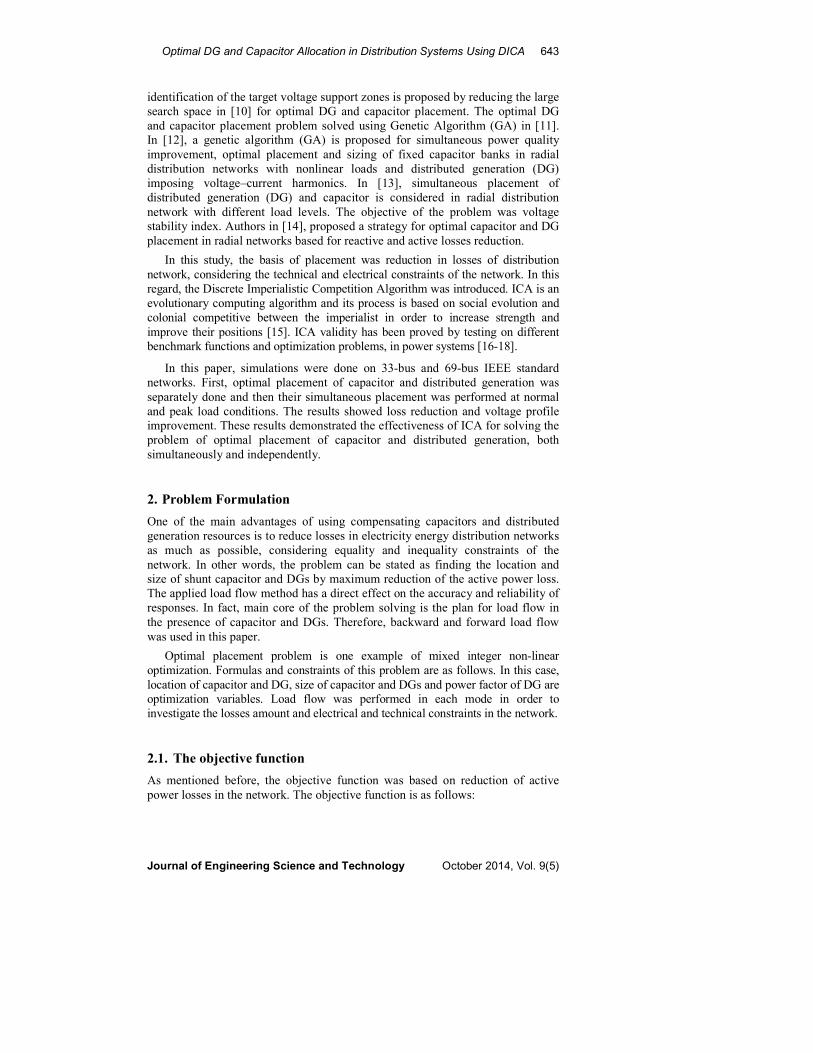
reliable and practically applicable in real distribution networks. Figure 1
demonstrates the complete flowchart of DICA. Considering the evolutionary
mechanism of this algorithm, in comparison with other methods, it can quickly
converge to the optimal value. In this paper a new assimilation mechanism is
proposed for DICA. All the results were obtained after 50 independent runs. In all
cases the DICA converges to same optimal results. Since the results had the same
responses and absolute minimums for several times of independent runs, their
responses could be used as reliable values. Details of the proposed algorithm are
explained in the proceeding sub-sections.
646 A. Mahari and A. Mahari
Journal of Engineering Science and Technology October 2014, Vol. 9(5)
Fig. 1. Flowchart of DICA.
3.1. The generating initial empires
The goal of all optimization algorithms is to find optimal solution, regarding
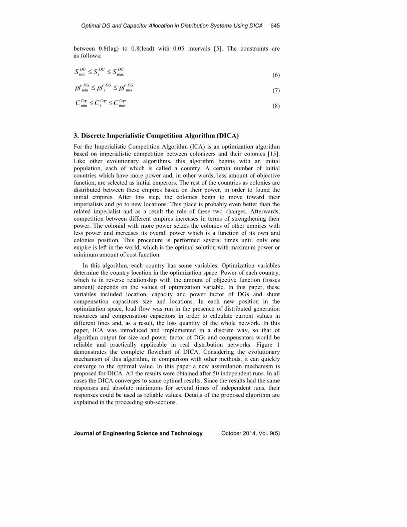
problem variables. In the DICA there is an array of discrete variables which have
to be optimized. In this paper the array variables are include buses numbers, size
of DG and capacitors and p.f. of DG units. Figure 2 shows a country structure.
Fig. 2. A Country Structure in Optima Placement Problem.
To start the optimization process, initial countries (population) are generated.
Then some of the most powerful countries are chosen as imperialists to form the
initial empires. The number of initial empires is assumed to be 10% of total initial
countries as advised in [15]. Once the initial countries are formed, colonies are
divided among imperialists based on their power, in proportion to the inverse of
their cost values.
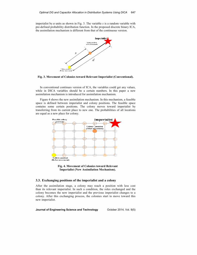
3.2. Moving the colonies of an empire toward the imperialist
At this stage, imperialists start to increase their colonies power. In the ICA, this
mechanism is modeled by moving colonies toward their relevant imperialists, as
shown in Fig. 3. In the continuous version of ICA, colony moves toward
{ {
( 3) ( 2)DG CN N× + ×
1
DGS1
DGBus 1. DGP F DGN
DGS DGN
DGBus . DGN
DGP F
1
CQ1
CBus CN
CQ CN
CBus
Optimal DG and Capacitor Allocation in Distribution Systems Using DICA 647
Journal of Engineering Science and Technology October 2014, Vol. 9(5)
imperialist by x units as shown in Fig. 3. The variable x is a random variable with
pre-defined probability distribution function. In the proposed discrete binary ICA,
the assimilation mechanism is different from that of the continuous version.
Fig. 3. Movement of Colonies toward Relevant Imperialist (Conventional).
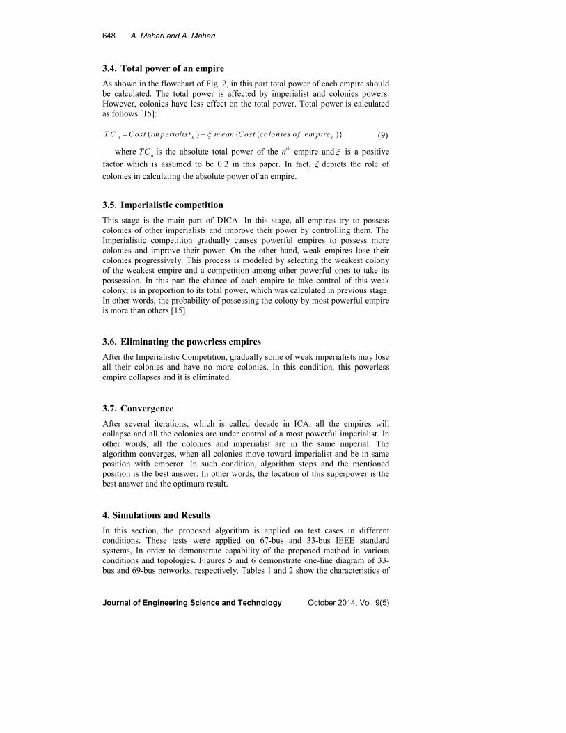
In conventional continues version of ICA, the variables could get any values,
while in DICA variables should be a certain numbers. In this paper a new
assimilation mechanism is introduced for assimilation mechanism.
Figure 4 shows the new assimilation mechanism. In this mechanism, a feasible
space is defined between imperialist and colony positions. The feasible space
contains some certain positions. The colony moves toward imperialist by
transferring from its current place to new one. The probabilities of all locations
are equal as a new place for colony.
Fig. 4. Movement of Colonies toward Relevant
Imperialist (New Assimilation Mechanism).
3.3. Exchanging positions of the imperialist and a colony
After the assimilation stage, a colony may reach a position with less cost
than its relevant imperialist. In such a condition, the roles exchanged and the
colony becomes the new imperialist and the previous imperialist changes to a
colony. After this exchanging process, the colonies start to move toward this
new imperialist.
x
d
648 A. Mahari and A. Mahari
Journal of Engineering Science and Technology October 2014, Vol. 9(5)
3.4. Total power of an empire
As shown in the flowchart of Fig. 2, in this part total power of each empire should
be calculated. The total power is affected by imperialist and colonies powers.
However, colonies have less effect on the total power. Total power is calculated
as follows [15]:
(9)
where nTC is the absolute total power of the nth empire and ξ is a positive
factor which is assumed to be 0.2 in this paper. In fact, ξ depicts the role of
colonies in calculating the absolute power of an empire.
3.5. Imperialistic competition
This stage is the main part of DICA. In this stage, all empires try to possess
colonies of other imperialists and improve their power by controlling them. The
Imperialistic competition gradually causes powerful empires to possess more
colonies and improve their power. On the other hand, weak empires lose their
colonies progressively. This process is modeled by selecting the weakest colony
of the weakest empire and a competition among other powerful ones to take its
possession. In this part the chance of each empire to take control of this weak
colony, is in proportion to its total power, which was calculated in previous stage.
In other words, the probability of possessing the colony by most powerful empire
is more than others [15].
3.6. Eliminating the powerless empires
After the Imperialistic Competition, gradually some of weak imperialists may lose
all their colonies and have no more colonies. In this condition, this powerless
empire collapses and it is eliminated.
3.7. Convergence
After several iterations, which is called decade in ICA, all the empires will
collapse and all the colonies are under control of a most powerful imperialist. In
other words, all the colonies and imperialist are in the same imperial. The
algorithm converges, when all colonies move toward imperialist and be in same
position with emperor. In such condition, algorithm stops and the mentioned
position is the best answer. In other words, the location of this superpower is the
best answer and the optimum result.
4. Simulations and Results
In this section, the proposed algorithm is applied on test cases in different
conditions. These tests were applied on 67-bus and 33-bus IEEE standard
systems, In order to demonstrate capability of the proposed method in various
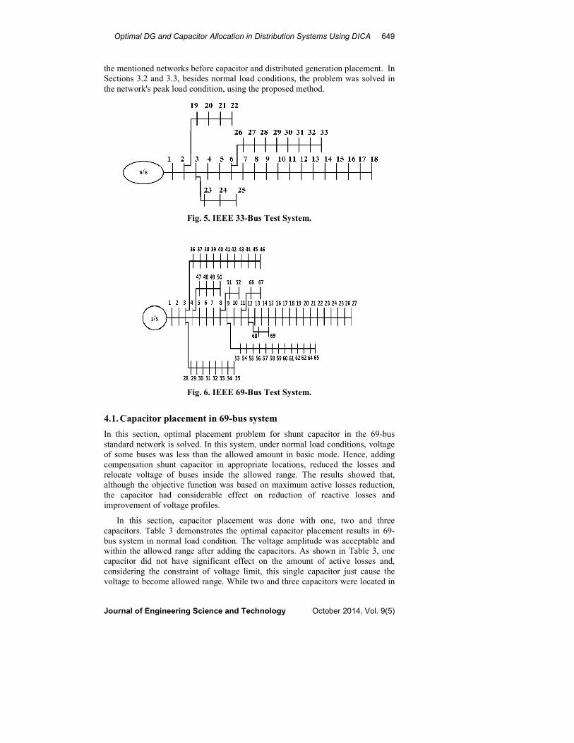
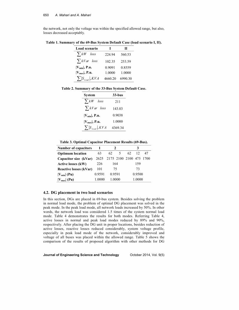
conditions and topologies. Figures 5 and 6 demonstrate one-line diagram of 33-
bus and 69-bus networks, respectively. Tables 1 and 2 show the characteristics of
( ) { ( )}n n nT C Cost im perialist m ean Cost colonies o f em pireξ= +
Optimal DG and Capacitor Allocation in Distribution Systems Using DICA 649
Journal of Engineering Science and Technology October 2014, Vol. 9(5)
the mentioned networks before capacitor and distributed generation placement. In
Sections 3.2 and 3.3, besides normal load conditions, the problem was solved in
the network's peak load condition, using the proposed method.
Fig. 5. IEEE 33-Bus Test System.
Fig. 6. IEEE 69-Bus Test System.
4.1. Capacitor placement in 69-bus system
In this section, optimal placement problem for shunt capacitor in the 69-bus
standard network is solved. In this system, under normal load conditions, voltage
of some buses was less than the allowed amount in basic mode. Hence, adding
compensation shunt capacitor in appropriate locations, reduced the losses and
relocate voltage of buses inside the allowed range. The results showed that,
although the objective function was based on maximum active losses reduction,
the capacitor had considerable effect on reduction of reactive losses and
improvement of voltage profiles.
In this section, capacitor placement was done with one, two and three
capacitors. Table 3 demonstrates the optimal capacitor placement results in 69-
bus system in normal load condition. The voltage amplitude was acceptable and
within the allowed range after adding the capacitors. As shown in Table 3, one
capacitor did not have significant effect on the amount of active losses and,
considering the constraint of voltage limit, this single capacitor just cause the
voltage to become allowed range. While two and three capacitors were located in
650 A. Mahari and A. Mahari
Journal of Engineering Science and Technology October 2014, Vol. 9(5)
the network, not only the voltage was within the specified allowed range, but also,
losses decreased acceptably.
Table 1. Summary of the 69-Bus System Default Case (load scenario I, II).
II I Load scenario
560.53 224.94
253.59 102.35
0.8559 0.9091 |Vmin|, P.u.
1.0000 1.0000 |Vmax|, P.u.
6990.30 4660.20
Table 2. Summary of the 33-Bus System Default Case.
33-bus System
211
143.03
0.9038 |Vmin|, P.u.
1.0000 |Vmax|, P.u.
4369.34
Table 3. Optimal Capacitor Placement Results (69-Bus).
3 2 1 Number of capacitors
47 12 62 5 62 63 Optimum location
1700 475 2100 2100 2175 2625 Capacitor size (kVar)
159 164 226 Active losses (kW)
73 75 101 Reactive losses (kVar)
0.9500 0.9591 0.9591 |Vmin| (Pu)
1.0000 1.0000 1.0000 |Vmax| (Pu)
4.2. DG placement in two load scenarios
In this section, DGs are placed in 69-bus system. Besides solving the problem
in normal load mode, the problem of optimal DG placement was solved in the
peak mode. In the peak load mode, all network loads increased by 50%. In other
words, the network load was considered 1.5 times of the system normal load
mode. Table 4 demonstrates the results for both modes. Referring Table 4,
active losses in normal and peak load modes reduced by 89% and 90%,
respectively. After placing the DG unit in proper locations, besides reduction of
active losses, reactive losses reduced considerably, system voltage profile,
especially in peak load mode of the network, considerably improved and
voltage of all buses was placed within the allowed range. Table 5 shows the
comparison of the results of proposed algorithm with other methods for DG
kW loss∑kVar loss∑
,LoadS KVA∑
kW loss∑kVar loss∑
,Load
S KVA∑
Optimal DG and Capacitor Allocation in Distribution Systems Using DICA 651
Journal of Engineering Science and Technology October 2014, Vol. 9(5)
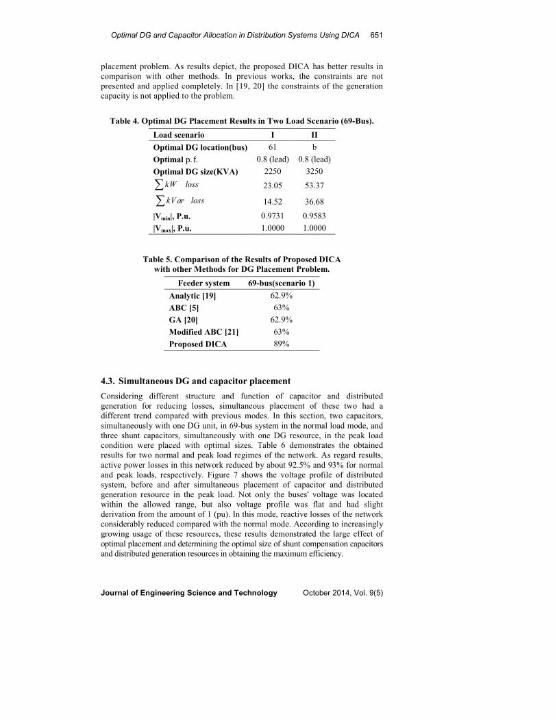
placement problem. As results depict, the proposed DICA has better results in
comparison with other methods. In previous works, the constraints are not
presented and applied completely. In [19, 20] the constraints of the generation
capacity is not applied to the problem.
Table 4. Optimal DG Placement Results in Two Load Scenario (69-Bus).
II I Load scenario
b 61 Optimal DG location(bus)
0.8 (lead) 0.8 (lead) Optimal p. f.
3250 2250 Optimal DG size(KVA)
53.37 23.05
36.68 14.52
0.9583 0.9731 |Vmin|, P.u.
1.0000 1.0000 |Vmax|, P.u.
Table 5. Comparison of the Results of Proposed DICA
with other Methods for DG Placement Problem.
Feeder system 69-bus(scenario 1)
Analytic [19] 62.9%
ABC [5] 63%
GA [20] 62.9%
Modified ABC [21] 63%
Proposed DICA 89%
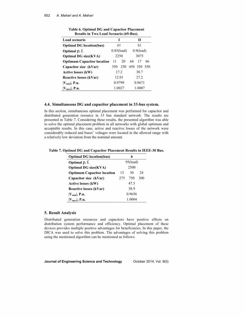
4.3. Simultaneous DG and capacitor placement
Considering different structure and function of capacitor and distributed
generation for reducing losses, simultaneous placement of these two had a
different trend compared with previous modes. In this section, two capacitors,
simultaneously with one DG unit, in 69-bus system in the normal load mode, and
three shunt capacitors, simultaneously with one DG resource, in the peak load
condition were placed with optimal sizes. Table 6 demonstrates the obtained
results for two normal and peak load regimes of the network. As regard results,
active power losses in this network reduced by about 92.5% and 93% for normal
and peak loads, respectively. Figure 7 shows the voltage profile of distributed
system, before and after simultaneous placement of capacitor and distributed
generation resource in the peak load. Not only the buses' voltage was located
within the allowed range, but also voltage profile was flat and had slight
derivation from the amount of 1 (pu). In this mode, reactive losses of the network
considerably reduced compared with the normal mode. According to increasingly
growing usage of these resources, these results demonstrated the large effect of
optimal placement and determining the optimal size of shunt compensation capacitors
and distributed generation resources in obtaining the maximum efficiency.
kW loss∑kVar loss∑
652 A. Mahari and A. Mahari
Journal of Engineering Science and Technology October 2014, Vol. 9(5)
Table 6. Optimal DG and Capacitor Placement
Results in Two Load Scenario (69-Bus).
II I Load scenario
61 61 Optimal DG location(bus)
0.9(lead) 0.85(lead) Optimal p. f. 3075 2250 Optimal DG size(KVA)
66 17 64 20 11 Optimum Capacitor location
550 350 450 250 350 Capacitor size (kVar)
38.7 17.2 Active losses (kW)
27.2 12.01 Reactive losses (kVar)
0.9671 0.9799 |Vmin|, P.u.
1.0007 1.0027 |Vmax|, P.u.
4.4. Simultaneous DG and capacitor placement in 33-bus system.
In this section, simultaneous optimal placement was performed for capacitor and
distributed generation resource in 33 bus standard network. The results are
presented in Table 7. Considering these results, the presented algorithm was able
to solve the optimal placement problem in all networks with global optimum and
acceptable results. In this case, active and reactive losses of the network were
considerably reduced and buses’ voltages were located in the allowed range with
a relatively low deviation from the nominal amount.
Table 7. Optimal DG and Capacitor Placement Results in IEEE-30 Bus.
6 Optimal DG location(bus)
95(lead) Optimal p. f. 2500 Optimal DG size(KVA)
24 30 13 Optimum Capacitor location
300 750 275 Capacitor size (kVar)
47.5 Active losses (kW)
38.9 Reactive losses (kVar)
0.9656 |Vmin|, P.u.
1.0004 |Vmax|, P.u.
5. Result Analysis
Distributed generation resources and capacitors have positive effects on
distribution system performance and efficiency. Optimal placement of these
devices provides multiple positive advantages for beneficiaries. In this paper, the
DICA was used to solve this problem. The advantages of solving this problem
using the mentioned algorithm can be mentioned as follows:

Optimal DG and Capacitor Allocation in Distribution Systems Using DICA 653
Journal of Engineering Science and Technology October 2014, Vol. 9(5)
5.1. Voltage profile
Among the tested cases, the 69-bus system in the peak load condition had the
most unfavorable voltage profile, compared with others. Figure 7 demonstrates
voltage profile of this network before and after simultaneous optimal placement
of DG unit and shunt capacitors. Figure 7 shows that although the objective
function was defined based on reduction of active losses, voltage profile was also
greatly improved. All the voltages of busses were within the allowed range and
the overall standard deviation was negligible compared with the basic mode,
before the placement.
Fig. 7. Voltage Profile of 69-Bus System
(Scenario II) before and after Placement.
5.2. Reduction in active losses
Considering the selection of active losses reduction as the objective function, the
obtained results were the most optimal ones in terms of active loss of the
distribution network. Figure 8 shows the losses amount in different modes.
According to Fig. 8, in the presence of DG and capacitors, losses reduced less to
about 17 kW.
Fig. 8. Active Power Losses Comparison in Different Cases.
0
50
100
150
200
250
Default
One
capacitor
Two
capacit…
Three
capacit…
DG
DG+
capacitorA
ctive losse (kW )
654 A. Mahari and A. Mahari
Journal of Engineering Science and Technology October 2014, Vol. 9(5)
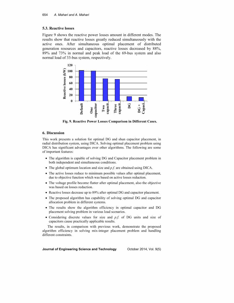
5.3. Reactive losses
Figure 9 shows the reactive power losses amount in different modes. The
results show that reactive losses greatly reduced simultaneously with the
active ones. After simultaneous optimal placement of distributed
generation resources and capacitors, reactive losses decreased by 88%,
89% and 73% in normal and peak load of the 69-bus system and also
normal load of 33-bus system, respectively.
Fig. 9. Reactive Power Losses Comparison in Different Cases.
6. Discussion
This work presents a solution for optimal DG and shun capacitor placement, in
radial distribution system, using DICA. Solving optimal placement problem using
DICA has significant advantages over other algorithms. The following are some
of important features:
• The algorithm is capable of solving DG and Capacitor placement problem in
both independent and simultaneous conditions.
• The global optimum location and size and p.f. are obtained using DICA.
• The active losses reduce to minimum possible values after optimal placement,
due to objective function which was based on active losses reduction.
• The voltage profile become flatter after optimal placement, also the objective
was based on losses reduction.
• Reactive losses decrease up to 89% after optimal DG and capacitor placement.
• The proposed algorithm has capability of solving optimal DG and capacitor
allocation problem in different systems.
• The results show the algorithm efficiency in optimal capacitor and DG
placement solving problem in various load scenarios.
• Considering discrete values for size and p.f. of DG units and size of capacitors cause practically applicable results.
The results, in comparison with previous work, demonstrate the proposed
algorithm efficiency in solving mix-integer placement problem and handling
different constraints.
0
20
40
60
80
100
120
Default
One
capacitor
Two
capacit…
Three
capacit…
DG
DG +
Capaci…
Reactive losses (kW)
Optimal DG and Capacitor Allocation in Distribution Systems Using DICA 655
Journal of Engineering Science and Technology October 2014, Vol. 9(5)
7. Conclusions
In this paper, an algorithm was introduced for loss reduction in distribution systems
by optimal allocation of DG and capacitor using discrete imperialistic competition
algorithm. The new DICA was proposed in this paper, with new assimilation
mechanism. The results shows the proposed DICA converges to same optimal
results after 50 independent runs, which prove the efficiency of proposed method in
solving DG and capacitor placement. The objective function was considered based
on active losses reduction. In all the simulations, technical and electrical constraints
were considered, in order for the values to be reliable and practical. The proposed
method was tested on the IEEE 69-bus standard test system in both normal load and
peak load modes and also in the normal load condition of 33-bus standard system.
The results not only demonstrated significant reduction in active losses, but also
show the great improved of other parameters network. In this paper, discrete
practical values were considered for capacitor and DG sizes, in order for the results
to be practically applicable. The obtained results indicated capability of the
proposed algorithm in solving non-linear mix-integer problem of optimal placement
of capacitor and DG, both separately and simultaneously.
References
1. Gallego, R.A.; Monticelli, A.; and Romero, R. (2001). Optimal capacitor
placement in radial distribution networks. IEEE Transactions on Power
Systems, 16(4), 630-637.
2. da Silva, C.; Carneiro, S.; de Oliveira, E.J.; de Souza Costa, J.; Pereira,
J.L.R.; and Garcia, P.A.N. (2008). A heuristic constructive algorithm for
capacitor placement on distribution systems. IEEE Transactions on Power
Systems, 23(4), 1619-1626.
3. Mekhamer, S.F.; El-Hawary, M.E.; Soliman, S.A.; Moustafa, M.A.; and
Mansour, M.M. (2002). New heuristic strategies for reactive power
compensation of radial distribution feeders. IEEE Transactions on Power
Delivery, 17(4), 1128-1135.
4. Chis, M.; Salama, M.M.A.; and Jayaram, S. (1997). Capacitor placement in
distribution systems using heuristic search strategies. IEE Proceedings
Generation, Transmission and Distribution, 144(3), 225-230.
5. Abu-Mouti, F.S.; and El-Hawary, M.E. (2011). Optimal distributed
generation allocation and sizing in distribution systems via artificial bee
colony algorithm. IEEE Transactions on Power Delivery, 26(4), 2090-2101.
6. Barker, P.P.; and De Mello, R.W. (2000). Determining the impact of
distributed generation on power systems part 1: Radial distribution systems.
Proceedings of IEEE Power Engineering Society Summer Meeting, 3,
1645-1656.
7. Acharya, N.; Mahat, P.; and Mithulananthan, N. (2006). An analytical
approach for DG allocation in primary distribution network. Electric Power
Systems Research, 28(10), 669-678.
8. Mahari, P.; and Babaei, E. (2012). Optimal DG placement and sizing in
distribution systems using imperialistic competition algorithm. IEEE 5th
India International Conference on Power Electronics (IICPE), 1-6.
656 A. Mahari and A. Mahari
Journal of Engineering Science and Technology October 2014, Vol. 9(5)
9. Wang, M.; and Zhong, J. (2011). A novel method for distributed generation
and capacitor optimal placement considering voltage profiles. Power and
Energy Society General Meeting, IEEE, 1-6.
10. Zou, K.; Agalgaonkar, A.P.; Muttaqi, K.M.; and Perera, S. (2009). Voltage
support by distributed generation units and shunt capacitors in distribution
systems. Power & Energy Society General Meeting, 1-8.
11. Kalantari, M.; and Kazemi, A. (2011). Placement of distributed generation unit
and capacitor allocation in distribution systems using genetic algorithm. 10th
International Conference on Environment and Electrical Engineering, 1-5.
12. Taher, S.A.; Hasani, M.; and Karimian, A. (2011). A novel method for
optimal capacitor placement and sizing in distribution systems with nonlinear
loads and DG using GA. Communications in Nonlinear Science and
Numerical Simulation, 16(2), 851-862.
13. Sajjadi, S.M.; Haghifam, M.R.; and Salehi, J. (2013). Simultaneous
placement of distributed generation and capacitors in distribution networks
considering voltage stability index. International Journal of Electrical Power
& Energy Systems, 46, 366-375.
14. Mahari, A.; and Mahari, A. (2012). Optimal capacitor and DG placement in
distribution system for loss reduction. 27th International Power System
Conference, 12-F-PDS-1589.
15. Gargari, E.A.; and Lucas, C. (2007). Imperialist competitive algorithm: An
algorithm for optimization inspired by imperialistic competition. Proceedings
of IEEE Congress Evolutionary Computation, 4661-4667.
16. Nojavan, M.; Seyedi, H.; Mahari, A.; and Zare, K. (2014). Optimization of
fuse-reclose coordination and dispersed generation capacity in distribution
systems. Majlesi Journal of Electrical Engineering, 8(3), 15-24.
17. Mahari, A.; and Zare, K. (2014). A solution to the generation scheduling
problem in power systems with large-scale wind farms using MICA.
International Journal of Electrical Power & Energy Systems, 54, 1-9.
18. Mahari, A.; and Seyedi, H. (2013). Optimal PMU placement for power
system observability using BICA, considering measurement redundancy.
Electric Power Systems Research, 103, 78-85.
19. Acharya, N.; Mahat, P.; and Mithulananthan, N. (2006) An analytical
approach for DG allocation in primary distribution network. Electric Power
Systems Research, 28(10), 669-678.
20. Shukla, T.N.; Singh, S.P.; Srinivasarao, V.; and Naik, K.B. (2010). Optimal
sizing of distributed generation placed on radial distribution systems.
Electrical Power Component System, 38(3), 260-274.
21. Abu-Mouti, S.; and El-Hawary, M.E. (2009). Modified artificial Bee Colony
algorithm for optimal distributed generation sizing and allocation in
distribution systems. IEEE Electrical Power & Energy Conference, 1-9.