optimisation of the iv generation tanks for hydrogen
TRANSCRIPT
Optimisation of the IV Generation Tanks for Hydrogen Stor-age Applied in Vehicles. Modelling and Experiment
J. Kaleta, W. Błazejewski, P. Gąsior, M. Rybaczuk
This document appeared in
Detlef Stolten, Thomas Grube (Eds.):18th World Hydrogen Energy Conference 2010 - WHEC 2010Parallel Sessions Book 4: Storage Systems / Policy Perspectives, Initiatives and Co-operationsProceedings of the WHEC, May 16.-21. 2010, EssenSchriften des Forschungszentrums Jülich / Energy & Environment, Vol. 78-4Institute of Energy Research - Fuel Cells (IEF-3)Forschungszentrum Jülich GmbH, Zentralbibliothek, Verlag, 2010ISBN: 978-3-89336-654-5

Optimisation of the IV Generation Tanks for Hydrogen Storage Applied in Vehicles. Modelling and Experiment
Jerzy Kaleta, Wojciech Błażejewski, Paweł Gąsior, Marek Rybaczuk, Wrocław University of Technology, Poland
1 Introduction
A prevalent technology is storing of hydrogen in a high pressure tanks/vessels (CH2) with increasing Nominal Working Pressure (NWP) to 70 MPa (vessel type IV). The outer layer of such vessel is made of high resistant carbon fibers and liner is made of high density plastics. A burst pressure (a safety ratio = 2.35), must be at least 164.5 MPa. Currently there is no vessel type IV on the market (omitting prototype vessels), which has sensible cost of production and fulfills all safety requirements at the same time. A high value of safety ratio cause that thickness of the composite layer of CH2 cylinders is at least 15 mm or even more. It brings a high price of complete storage system and exclude its mass applicability. The main efforts are presently focused on optimization of the production technology in order to mass and cost reduction. This requires application of new ideas of numerical modeling, experimental identification and sensoring. Good numerical model should allow: description of winding geometry, description of the stress and strain states in vessel for mezo- and macroscales, formulation of the problem of initiation of material damage, acceptance of quantity responsible for damage accumulation and formulation of fatigue hypothesis. The model should indicate location of sensors and their number what constitutes basis for experiment. The paper presents briefly selected methods of modelling and way of experimental verification of proposed models. Some results were obtained under StorHy project (6FP, Integrated Project), InGas project (7FP) and Polish research project No. POIG.01.01.02-00-016/08.
2 Geometry of Winding Composite Layers. Modelling
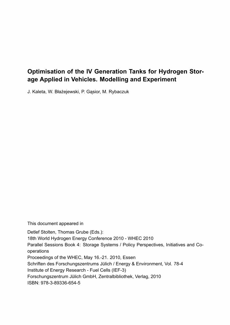
Analysis within construction of composite tank as well as applied structures of composite carrying layer in both cases CNG and CH2 bottles manufactured by leading firms in world allows to conclude that every manufacturer makes use of different arrangement of fibres. There are no differences in materials applied for a liner and braid, actually it is carbon fibres and aluminium or thermoplastic (IV generation) liner. However there are substantial discrepancies in composite carrying layer of tanks. Especially this concerns number of wound layers, angle of winding, layers sequence and finishing of outer layer, etc. This means that there is no widely accepted and documented methods of choice and determination of composite carrying layer. This problem is especially important in the case of designing of tanks, what is called fourth generation CH2. Our team has elaborated universal method of generation of interlace geometry and its application with the help of winders. It was proofed that only finite number of patterns is available. The Figure 1 below presents only four geometries around many possible. Experiment indicates that some structures allow reduction
Proceedings WHEC2010 25
of composite layer thickness thus reduction of mass and price without changes in safety requirements (level of strain, damage accumulation).
Figure 1: Diagrams of geometry of four chosen interlacing of wound fibres made with the help of
winder.
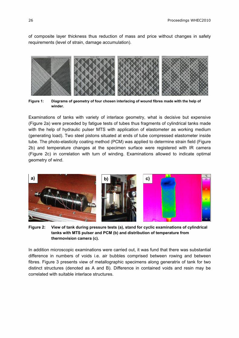
Examinations of tanks with variety of interlace geometry, what is decisive but expensive (Figure 2a) were preceded by fatigue tests of tubes thus fragments of cylindrical tanks made with the help of hydraulic pulser MTS with application of elastometer as working medium (generating load). Two steel pistons situated at ends of tube compressed elastometer inside tube. The photo-elasticity coating method (PCM) was applied to determine strain field (Figure 2b) and temperature changes at the specimen surface were registered with IR camera (Figure 2c) in correlation with turn of winding. Examinations allowed to indicate optimal geometry of wind.
Figure 2: View of tank during pressure tests (a), stand for cyclic examinations of cylindrical tanks with MTS pulser and PCM (b) and distribution of temperature from thermovision camera (c).
In addition microscopic examinations were carried out, it was fund that there was substantial difference in numbers of voids i.e. air bubbles comprised between rowing and between fibres. Figure 3 presents view of metallographic specimens along generatrix of tank for two distinct structures (denoted as A and B). Difference in contained voids and resin may be correlated with suitable interlace structures.
26 Proceedings WHEC2010

Figure 3: View of metallographic specimens (50X) along generatrix of tank for two different structures denoted as A and B. The substantial difference in voids and resin contents is clearly visible.
3 Modelling of Strain State and Damage Accumulation of Tank
Examination of running damage process and current damage level may be effectively performed as an effect of some hybrid procedure, i.e. it should consist of well verified numerical model (of the multi-scale type) of vessel together with local measurements making use of well located limited number of sensors. Good numerical model (for every type of vessel) should allow:
description of winding geometry (so called parquet problem, described above), the constitutive equation of composite (making use of some homogenization
procedure for example) description of the stress and strain states in vessel (applying the model of continuum
and FEM), formulation of the problem of initiation of material damage, acceptance of quantity responsible for damage accumulation (measure of damage)
and formulation of fatigue hypothesis. The model should indicate location of sensors and their number what constitute basis for experiment. Dominating, till recent times, metal constructional materials and elaborated modelling methods are useless in the case of carbon/polymeric composites for high pressure vessels application. Here, the structure, orientation of fibres and interaction between fibres and epoxide matrix, have decisive meaning. Classical models do not provide reasonable safety of construction during computer aided designing. In turn, such modelling reduces costs of experimental works what entails reduction of construction costs. In practice effective methods of modelling becomes unavoidable. Modelling of materials with complicated internal structure (corresponding to sufficiently short scales or equivalently to sufficient magnifications of observations) remains still an open problem. Modern constructional materials like fiber reinforced composites constitute a challenge. The basic problem is to find the correspondence between visible microscopic
Proceedings WHEC2010 27

structure and material properties, mainly mechanical ones, responsible for macro scales usually put forward in engineering applications. The identification of material parameters based on experimental measurements has the key meaning. The experiment should allow:
local measurements of strain at places indicated by the model (here, application of optical fibers sensors is preferred)
measurement of quantity correlated with accumulation of damage of vessel (registration of AE for example),
modelling and experiments for vessels (expensive ones) may be preceded by modelling and experiments for tube specimens.
Especially useful In modelling of composite structures applied in tanks construction approaches are listed below [3,4,5,6]:
Modelling making use of nonstandard models of continual media (using homoganisation),
Modelling in terms of cellular automata, Modelling applying theory of dynamical systems.
Below only chosen aspects are briefly presented. Modelling making use of nonstandard models of continual media. The main purpose of modelling of composite materials is establishing of constitutive equations describing entire large specimens due to known structure and material properties of separate phases forming composite as well as architecture of fibres (transition from micro through meso to large scales). The homogenisation method allows determination of material properties (for example Young module) and it consists in suitable averaging over chosen volume and over separate phases properties. At macro level, the structure of composite becomes invisible but one knows the stress-strain dependence which in fact corresponds to phase and fibres properties. It is possible to assume that fibre reinforced polymeric composites have periodic structure what enables establishing of the Representative Volume Element (RVE).
Figure 4: The structure and quarter of Representative Volume Element (a) and division of a quarter of unit cell into subcells in plane material properties homogenisation (b).
28 Proceedings WHEC2010

We predict the behaviour of composite making use the found RVE and the homogenisation procedure. According to distribution of fibres the RVE may be decomposed into subcells (Figure 4b) and the homogenisation procedure may run in few steps. In turn application of fractal geometry methods allows modelling of acoustic emission (AE). Numerically simulated acoustic events may be compared with acoustic events registered during experimental examinations of specimens and pressure vessels.
4 Sensors, Measurements Methods
The problem of strain measurements and establishing of on board monitoring system [7,8,9,10], which may be applied during manufacturing phase and many years of its exploitation was presented in accompanying paper (Smart fibre optic methods for structural health monitoring of high pressure vessels for hydrogen storage. WHEC 2010; Vehicle and Infrastructure Safety/SI.1).
Figure 5: Scheme of FBG sensors arrangement (a) and SOFO® (b) and view of the braided structure with sensors installed on the penultimate braided layer [9].
Above, only ways of integration of optic fibres sensors FBG and SOFO® inside composite structure made up with braiding technique were presented (Figure 5). Digits 1,2,3,...,6 indicated positions of optical fiber sensors (FBG). System was tested for a pilot vessels made up from glass fibres. Another effective measurement techniques were thermovision, photo-elastic method of surface layer, acoustic emission (for accumulation of damages). Resistance strain gauge method has limited importance.
5 Static and Fatigue Tests of Vessels
Norms assume that experimental examinations are decisive and cannot be replaced with modelling procedures. Therefore the special laboratory for high pressure tests was created at Institute of Materials Science and Applied Mechanics, Wroclaw University of Technology. Among others, it carries cyclic test within the range of pressures 2÷150 MPa (under room
Proceedings WHEC2010 29

temperatures and under extreme conditions , -45ºC, +80ºC and 90% humidity) as well as burst tests up to 200 MPa. There are also testing ground examinations (for example shoot down tests with penetrating bullet). Due to regulations the cyclic load test of tanks is carried out with the help of oil, up do damage or up to approaching 45000 tests in stages of 15000 cycles. Loads amount 20÷875 bars for Hydrogen with frequency not exceeding 10 cycles per minute (usually 2 cycles per minute).
Figure 6: Hydraulic stand for cyclic examinations of vessels (a), stand for static tests of high pressure vessels (b) and vessel in safety chamber after burst test (c) [6].
In turn static tests, including burst tests, are carried out at stand depicted in Figure 6b. Maximal available pressure amounts 3000 bars. Before tests vessels are filled with water and degassed, next they become inserted in safety chamber.
6 Summary
1. Manufacturing of safety, light and relatively cheap composite tank of fourth generation for Hydrogen storage as fuel requires works on optimisation of wound geometry, modelling of effort state, damage accumulation and methods of modelling as well as application of sensors.
2. Methods of modelling allow substantially reduction of costs within constructions, technology and examination of CH2 tanks.
3. Experimental examinations still remain decisive especially within static and cyclic loads of bottles.
References [1] Błażejewski W.: Influence of the winding fibers structures on mechanical strength of
composite cylinder elements made up from epoxy-glass. W: 17th Danubia-Adria Symposium on Experimental Method in Solid Mechanics, Prague, October 11-14, 2000.
[2] Blazejewski W., Gasior P., Kaleta J.: Burst test of high pressure composite vessels for gasoues fuels storage. W: 25th Danubia-Adria Symposium on Advances in Experimental Mechanics, Ceske Budejovice, Cesky Krumlov, Czech Republic, September 24-27, 2008.
30 Proceedings WHEC2010
[3] Czapliński T., Maciejewski Ł., Przygoda A., Ziętek G. A model of textile reinforced composite; homogenisation and identification. 18th Conference on CMM. Zielona Góra, Poland, 2009, pp. 155-156.
[4] Aniszewska D., Rybaczuk M., Fractal characteristics of defects evolution in parallel fibre reinforced composite in quasi-static process of fracture, Theoretical and Applied Fracture Mechanics, 52, (2009), 91-95.
[5] Czopor J., Rybaczuk M., Fibers breaking process in composites models and numerical simulations applying cellular automata, Theoretical and Applied Fracture Mechanics, 52, (2009), 154-157.
[6] Aniszewska D., Rybaczuk M., Modelling defects growth in composites using fractals characteristics, Composites2009 2nd ECCOMAS, Thematic Conference on the Mechanical Response of Composites, 1-3 April 2009, Imperial College London, UK.
[7] Gasior P., Kaleta J., Sankowska A.: Optical fiber sensors in health monitoring of composite high pressure vessels for hydrogen, Proc. SPIE s. 66163G-1-66163G-10, cop. 2007.
[8] Blazejewski W., Gasior P., Kaleta J., Sankowska A..: Optical Fiber Sensors as NDT methods for strain state monitoring of high pressure composites vessels. Comparison of different types of OFS. 8th International Conference on Durability of Composite Systems, 16-18 July 2008, Porto, Portugal.
[9] Blazejewski W., Czulak A., Gasior P., Kaleta J., Mech R.: SMART composite high pressure vessels with integrated Optical Fiber Sensors. SPIE Smart Structures/NDE, San Diego, California, USA, 7 - 11 March 2010.
[10] Blazejewski W., Gasior P., Kaleta J., Sankowska A.: Optical fiber sensors integrated with composite material based constructions. Lightguides and Their Applications III, Proc. SPIE s. 66081L-1-66081L-10, cop. 2007.
Proceedings WHEC2010 31