optimization and cfd analysis of a shell-and-tube …
TRANSCRIPT
Aydin, A., et al.: Optimization and CFD Analysis of a Shell-and-Tube Heat ... THERMAL SCIENCE: Year 2022, Vol. 26, No. 1A, pp. 1-12 1
OPTIMIZATION AND CFD ANALYSIS OF A SHELL-AND-TUBE HEAT EXCHANGER WITH A MULTI SEGMENTAL BAFFLE
by
Ahmet AYDIN a, Halit YASAR b, Tahsin ENGIN b*, and Ekrem BUYUKKAYA b
a Metallurgical and Materials Engineering Department, Engineering Faculty, Sakarya University, Sakarya, Turkey
b Mechanical Engineering Department, Engineering Faculty, Sakarya University, Sakarya, Turkey
Original scientific paper https://doi.org/10.2298/TSCI200111293A
The shell-and-tube type heat exchangers have long been widely used in many fields of industry. These types of heat exchangers are generally easy to design, manufac-turing, and maintenance, but require relatively large spaces to install. Therefore, the optimization of such heat exchangers from thermal and economical points of view is of particular interest. In this article, an optimization procedure based on the minimum total cost (initial investment plus operational costs) has been ap-plied. Then the flow analysis of the optimized heat exchanger has been carried out to reveal possible flow field and temperature distribution inside the equipment using CFD. The experimental results were compared with CFD analyses results. It has been concluded that the baffles play an important role in the development of the shell side flow field. This prompted us to investigate new baffle geometries without compromising from the overall thermal performance. It has been found that the heat exchanger with the new baffle design gives rise to considerably lower pressure drops in the shell side, which in turn reducing operating cost. The new baffle design is particularly well suited for shell-and-tube heat exchangers, where a viscous fluid-flows through shell side with/out phase change.Key words: shell-and-tube heat exchanger, optimization, multi segmental baffle,
CFD analysis, optimal design
Introduction
Heat exchangers are devices used for transferring thermal energy between a solid object and a fluid, or between two or more fluids. The fluids may be separated by a solid wall to prevent mixing or they may be in direct contact. They are widely used in space heating, refriger-ation, air conditioning, power stations, petrochemical, chemical and pharmaceutical industries, natural gas processing and wastewater treatment [1-4]. Among these, shell-and-tube heat ex-changers are the most commonly used ones. In this system, heat transfer performance depends on many parameters such as placement of tubes, number of baffles, number of tubes and length. These heat exchangers have a lot of advantageous, such as having a high ratio of volume and heat transfer area, easier cleaning, manufacturing and repairing, and to be able to transfer high mass-flow rates. However, it is possible to improve the performance of a heat exchanger by
* Corresponding author, e-mail: [email protected]

Aydin, A., et al.: Optimization and CFD Analysis of a Shell-and-Tube Heat ... 2 THERMAL SCIENCE: Year 2022, Vol. 26, No. 1A, pp. 1-12
changing baffle geometry. Since the flow direction may be guided with these component, the whole heat transfer area is involved in the heat transfer and the velocities and the turbulence may be higher due to the decreased flow section. Thus, this improved value may provide high-er heat transfer coefficient and heat performance. However, one of the major constraints that stands in the way of optimizing its thermal design is the pressure drop.
Pressure drop is an important constraint in thermal design of shell-and-tube heat ex-changers. Thermal design of a shell-and-tube heat exchanger is meaningful solely when it is optimum and the value of this is constrained by the pressure drop. As a result, optimization of thermal design requires maximization of overall heat transfer coefficient and effective mean temperature difference so as to minimize the heat transfer area subject to the constraints, pres-sure drop being the major one. The pressure drop should be managed in such a way that the calculated pressure drop is within and as close as possible to the allowable pressure drop. That is, when the pressure drop has a limiting effect during thermal design, the calculated pressure value should be reduced so that it does not exceed the permissible pressure drop. Moreover, drop in the determined pressure value should be as close as possible to the permissible pressure drop when the pressure drop during the thermal design is high [5].
Accurate determination of acceptable pressure drops in a heat exchanger design is possible by repeating several experiments many times. However, the fact that heat exchangers with a wide range of applications can be operated under the most economical conditions de-pends primarily on the fact that the pressure drops are objectively determined [2]. This pressure drop for both fluids sets the initial investment cost of the heat exchanger as well as the cost of energy and the initial investment cost of the pump or compressor required to heat the fluids. However, in many applications, the pressure drop values given for the heat exchanger design are usually not determined objectively.
Various studies have been carried out for the optimization of shell-and-tube type heat exchangers. Two different methods were used in these studies. One of them is Kern [6] and the other one is the Bell-Delaware method [7]. Kern method gives conservative results, suitable for the preliminary sizing. On the other hand, Bell-Delaware method is a detailed accurate in estimating heat transfer coefficient and the pressure drop on the shell side for common geomet-ric arrangements. Bell-Delaware method indicates the existence of possible weaknesses in the shell side design, but does not point out where these weaknesses are.
Investigations were carried out taking into account the pressure drops in the heat exchanger. The first of these is McAdams [8]. This researcher derived two expressions that give optimum heat flux for the unit heat energy. In heat exchanger cost optimization, some of the researchers used Lagrange multipliers and geometric programming techniques. In order to apply these methods, algebraic expressions are needed which express the bound-ary functions and the objective functions correctly. Babu and Shaik [9] performed optimal design of shell-and-tube type heat exchangers using ten different strategies in differential evolution method. Leoni et al. [10] investigated the effect of the usage of different turbu-lence model while Ambekar et al. [11] studied four different segmental baffle types, such as single, double, triple and flower. Irshad et al. [12] done comparison for several shell-and-tube heat exchangers with segmental baffles. Their simulation studies shown how the tem-perature, pressure, velocity varies in shell due to different baffles orientation. Markosvska et al. [4] made the optimal design of trunk tube heat exchangers by providing simultaneous solutions of equations using a software package. Ravagani et al. [13] solved an optimi-zation problem with a shell-and-tube heat exchanger design, the objective function cost being the least, by using the formulation and the particle swarm optimization method. Abd

Aydin, A., et al.: Optimization and CFD Analysis of a Shell-and-Tube Heat ... THERMAL SCIENCE: Year 2022, Vol. 26, No. 1A, pp. 1-12 3
and Naji [14] examined the method of Kern to define the external heat transfer coefficient. Bhandurge et al. [15] done investigation along with CFD simulation on single pass, counter flow shell-and-tube heat exchanger at 0°, 15°, 30°, 45°, and orientation. They examined the heat transfer rate and pressure drop of shell side fluid with Bell-Delaware method. Edwards [16] evaluated the fundamental aspects of the thermal design of trunk tube heat exchangers. Ponce et al. [17] solved a compact formulation of the Bell-Delaware method proposed for optimal shell-and-tube heat exchanger design using genetic algorithm. Varga et al. [18] studied helical baffles for the more favorable flow regulation. Azad and Amidpour [19] used the new approach of structural theory to make the optimal design of shell-and-tube type heat exchangers economical. Shrikant et al. [20] replaced a segmental tube bundles by a bundle of tubes with helical baffles in a shell-and-tube heat exchanger to reduce pressure drop and fouling and hence reduce maintenance and operating cost in Tabriz Petroleum Company. Using the genetic algorithm, Sanaye and Hajabdollahi [21] solved objective function optimization using the genetic algorithm, with the shell-and-tubular heat exchang-ers being the most efficient and least expensive. Jegede and Polley [22] go for a very useful and simple method innovation for heat exchanger optimization. Engin and Gungor [23] have applied this method to different types of heat exchangers on the shell-and-tube type heat exchangers.
In this study, a new type of baffle called multi segmental baffle was proposed for use in shell-and-tube heat exchangers. Then, this heat exchanger was optimized using the method pro-posed by Jegede and Polley [22]. In the study, the results of CFD analysis of the heat exchanger with multi segmental baffle were compared to the heat exchanger with conventional baffles. The heat exchanger produced according to the optimization results was tested and the results were compared with the CFD analysis results for the same heat exchanger.
Optimization methodology
In this study, the optimization method developed by Jegede and Polley [22] was ad-opted. The heat transfer rate of a heat exchanger, that is, the amount of heat transmitting from the hot fluid to the cold fluid is expressed:
( ) [ ] ( ) [ ]h c h ch ch c, ,p pQ mC T Q mC T Q Q= ∆ = ∆ =
(1)
where ṁ is mass-flow rate, Cp – the specific heat of the fluid, ΔT – the temperature differ-ence of the fluid, and the subscripts c and h refer to cold and hot fluids, respectively. The following equation is used to express the heat transfer rate based on logarithmic temperature difference on the shell-and-tube sides:
mQ KA T= ∆ (2)where ΔTm is the logarithmic temperature dif-ference, fig. 1. By neglecting the wall thick-ness of tubes, as well as fouling effects, total heat transfer coefficient can be expressed:
s t
1 1 1
K
h h
=+ (3) Figure 1. Calculation of logaritmic
temperature difference
Length
Tem
pera
ture
� T T T1 = –ti so
Tti
Tso
Tto
Tsi
� T T T2 = –to si
Tsi
TtoTti
Tso
Aydin, A., et al.: Optimization and CFD Analysis of a Shell-and-Tube Heat ... 4 THERMAL SCIENCE: Year 2022, Vol. 26, No. 1A, pp. 1-12
1 2
1
2
log
mT TT
TT
∆ −∆∆ =
∆ ∆
(4)
Shell-and-tube side pressure drops were given by Jegede and Polley [22]:3.5
t t tP C Ah∆ = (5)
5.1s s sAhP C∆ = (6)
where Ct and Cs are the constants depending on geometric properties of the heat exchanger as well as thermophysical properties of the fluids. The cost components of a heat exchanger sys-tem to be taken as basis for optimization are the initial cost and the operating cost:
t he opC C C= + (7)
where Che is the initial investment cost of the heat exchanger and Cop is the cost of energy con-sumption of the system. The initial investment cost of the heat exchanger is expressed by the following equation [23].
he 1 2s t
1 1C C Ch h
= + +
(8)
The operation cost is the energy consumption cost required to overcome the pressure drop of the pump and was given by [23]:
5.1 3.54.1 5.1 2.5 3.5s t
op 3 t 4 s 5 t 4 tt s
h hC C h C h C h C h
h h
= + + + + +
(9)
The total cost function is consequently given as a function of shell-and-tube sides convective heat transfer coefficients:
5.1 3.54.1 5.1 2.5 3.5s t
1 2 3 t 4 s 5 t 4 ts t t s
1 1 th h
C C C C h C h C h C hh h h h
= + + + + + + + +
(10)
Minimizing the aforementioned equation will also optimize the cost. Thus, the follow-ing equations are obtained when the eq. (10) are derived according to hs and ht and equalized to zero:
( ) t1 s t
s, 0
Cf h h
h∂
= =∂
(11)
( ) t2 s t
t, 0
Cf h h
h∂
= =∂
(12)
The roots of the equation were calculated as hs and ht. For the solution of two non-lin-ear equations with two unknowns, the program created on MATLAB was used. After optimized hs and ht were evaluated. Geometric parameters were calculated as shown in tab. 1.

Aydin, A., et al.: Optimization and CFD Analysis of a Shell-and-Tube Heat ... THERMAL SCIENCE: Year 2022, Vol. 26, No. 1A, pp. 1-12 5
Table 1. Parameters of the heat exchanger used in CFD analysisTube-side Shell-Side
h = 6817 W/m2K h = 3240 W/m2K
Velocity 0.8 m/s Velocity 0.38 m/s
Tube number 37 Shell diameter 0.161 mSurface area 2.8 m2 Distance between baffles 0.193 mLength 1.4 m Baffle number 6Pressure drop 736 Pa Pressure drop 736 Pa
Design parameters and CFD model
For optimization of the heat exchanger, the mass-flow rates of water through the inner tubes and the shell surface were 3.3 kg/s and 2.51 kg/s, respectively, which was given in tab. 2. For shell side, the inlet water temperature is 10 °C. The outlet water temperature is 30 °C. For tube-side, the inlet water temperature is 130 °C. The outlet water temperature is 115 °C In order to clearly see the characteristic differences, the analysis was carried out for the case where the temperature difference was highest for the shell side and the tube side. In the optimization studies, the economic life of the heat exchanger, the total working time, the pump efficiency, the total fouling resistance, the energy unit cost and the annual real interest rate were taken as 15 years, 8000 hours, 70%, 0.00036 kg/ms, 0.070 $/kWh, and 7%, respectively.
Table 2. Fluid properties
Parameter Water (Tube side)(Tmean = 122.5 °C)
Water (Shell side)(Tmean = 20 °C)
Mass-flow rate [kgs–1] 3.30 2.51Density [kgm–3] 941.25 998Specific heat [kJkg–1K–1] 4.249 4.182Kinematic viscosity [kgm–1s–1] 0.683 0.598Prandtl number 1.3025 7.01
As a result of optimization of the heat exchanger, the input geometric parameters giv-en in tab. 3 were obtained and these data were used in CFD analysis.
Table 3. Geometric parameters of the heat exchanger used in CFD analysisTube-side Shell-Side
Tube number 37 Shell diameter 0.161 mLength 1.4 m Baffle number 6
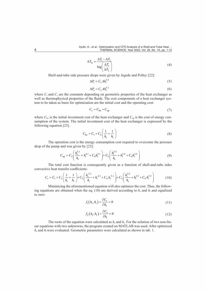
Based on the optimization results obtained first in the CFD analysis developed with the ANSYS FLUENT program, the flow geometry is modeled with the separate design modeler for the conventional and multi segmental baffle shell-and-tube model. In these models, two sep-arate control volumes are modeled to examine the shell side and tube side flows. For simplicity of solution, symmetry of the model showing symmetry feature was taken and the number of solution networks was reduced by half. The heat exchanger models with multi segmental and conventional baffles are shown in fig. 2.
Aydin, A., et al.: Optimization and CFD Analysis of a Shell-and-Tube Heat ... 6 THERMAL SCIENCE: Year 2022, Vol. 26, No. 1A, pp. 1-12
(a) (b)
Figure 2. Multi segmental and conventional baffle shell-and-tube heat exchanger models; (a) multi segmental baffle and (b) conventional baffle
The most important advantage of multi segmental baffle is creating local turbulence zone. Thus, the dead zones are eliminated for the shell side by using the multi segmental baf-fle. The details of multi segmental baffle are shown in fig. 3.
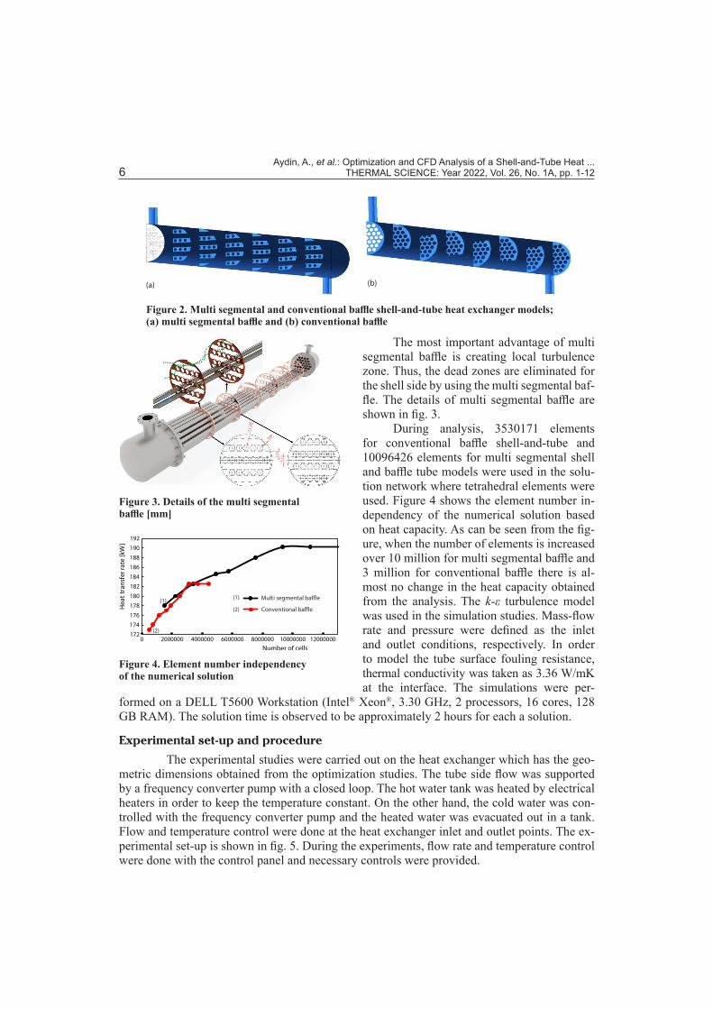
During analysis, 3530171 elements for conventional baffle shell-and-tube and 10096426 elements for multi segmental shell and baffle tube models were used in the solu-tion network where tetrahedral elements were used. Figure 4 shows the element number in-dependency of the numerical solution based on heat capacity. As can be seen from the fig-ure, when the number of elements is increased over 10 million for multi segmental baffle and 3 million for conventional baffle there is al-most no change in the heat capacity obtained from the analysis. The k-ε turbulence model was used in the simulation studies. Mass-flow rate and pressure were defined as the inlet and outlet conditions, respectively. In order to model the tube surface fouling resistance, thermal conductivity was taken as 3.36 W/mK at the interface. The simulations were per-
formed on a DELL T5600 Workstation (Intel® Xeon®, 3.30 GHz, 2 processors, 16 cores, 128 GB RAM). The solution time is observed to be approximately 2 hours for each a solution.
Experimental set-up and procedure
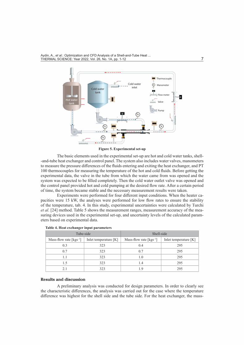
The experimental studies were carried out on the heat exchanger which has the geo-metric dimensions obtained from the optimization studies. The tube side flow was supported by a frequency converter pump with a closed loop. The hot water tank was heated by electrical heaters in order to keep the temperature constant. On the other hand, the cold water was con-trolled with the frequency converter pump and the heated water was evacuated out in a tank. Flow and temperature control were done at the heat exchanger inlet and outlet points. The ex-perimental set-up is shown in fig. 5. During the experiments, flow rate and temperature control were done with the control panel and necessary controls were provided.
Figure 3. Details of the multi segmental baffle [mm]
Figure 4. Element number independency of the numerical solution
172
174
176
178
180
182
184
186
188
190
192
0 2000000 4000000 6000000 8000000 10000000 12000000
Hea
ttra
nsfe
rrat
e[k
W]
Number of cells
Multi segmental baffle
Conventional baffle
(1)
(2)(1)
(2)
Aydin, A., et al.: Optimization and CFD Analysis of a Shell-and-Tube Heat ... THERMAL SCIENCE: Year 2022, Vol. 26, No. 1A, pp. 1-12 7
Figure 5. Experimental set-up
The basic elements used in the experimental set-up are hot and cold water tanks, shell- -and-tube heat exchanger and control panel. The system also includes water valves, manometers to measure the pressure differences of the fluids entering and exiting the heat exchanger, and PT 100 thermocouples for measuring the temperature of the hot and cold fluids. Before getting the experimental data, the valve in the tube from which the water came from was opened and the system was expected to be filled completely. Then the cold water outlet valve was opened and the control panel provided hot and cold pumping at the desired flow rate. After a certain period of time, the system became stable and the necessary measurement results were taken.
Experiments were performed for four different input conditions. When the heater ca-pacities were 15 kW, the analyses were performed for low flow rates to ensure the stability of the temperature, tab. 4. In this study, experimental uncertainties were calculated by Turchi et al. [24] method. Table 5 shows the measurement ranges, measurement accuracy of the mea-suring devices used in the experimental set-up, and uncertainty levels of the calculated param-eters based on experimental data.
Table 4. Heat exchanger input parametersTube-side Shell-side
Mass-flow rate [kgs–1] Inlet temperature [K] Mass-flow rate [kgs–1] Inlet temperature [K]0.3 323 0.4 2950.7 323 0.7 2951.1 323 1.0 2951.5 323 1.4 2952.1 323 1.9 295
Results and discussion
A preliminary analysis was conducted for design parameters. In order to clearly see the characteristic differences, the analysis was carried out for the case where the temperature difference was highest for the shell side and the tube side. For the heat exchanger, the mass-
Aydin, A., et al.: Optimization and CFD Analysis of a Shell-and-Tube Heat ... 8 THERMAL SCIENCE: Year 2022, Vol. 26, No. 1A, pp. 1-12
flow rates of water through the inner tubes and the shell surface were 3.3 kg/s and 2.51 kg/s, respectively. For shell side, the inlet water temperature is 10 °C. The outlet water temperature is 30 °C. For tube-side, the inlet water temperature is 130 °C. The outlet water temperature is 115 °C.
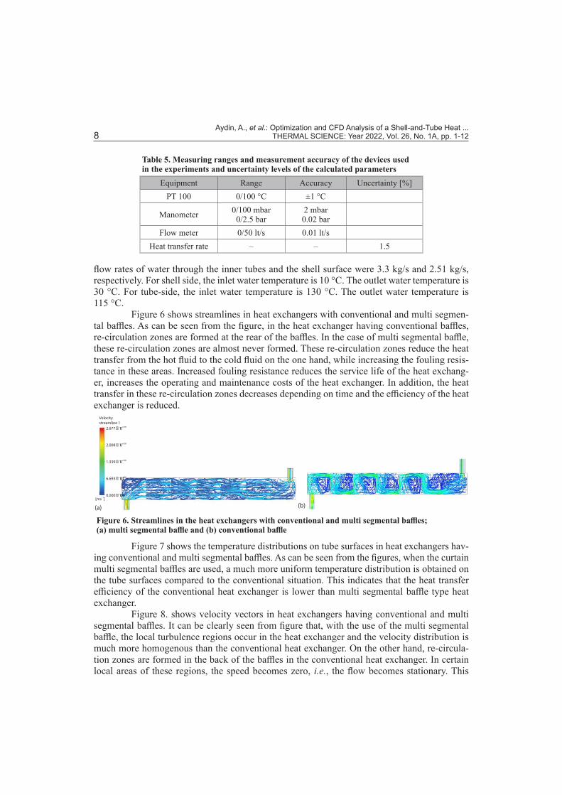
Figure 6 shows streamlines in heat exchangers with conventional and multi segmen-tal baffles. As can be seen from the figure, in the heat exchanger having conventional baffles, re-circulation zones are formed at the rear of the baffles. In the case of multi segmental baffle, these re-circulation zones are almost never formed. These re-circulation zones reduce the heat transfer from the hot fluid to the cold fluid on the one hand, while increasing the fouling resis-tance in these areas. Increased fouling resistance reduces the service life of the heat exchang-er, increases the operating and maintenance costs of the heat exchanger. In addition, the heat transfer in these re-circulation zones decreases depending on time and the efficiency of the heat exchanger is reduced.
(a) (b)
Velocitystreamline 1
2.677 � 10+000
2.008 � 10+000
1.339 � 10+000
6.693 � 10–000
0.000 � 10+000
[ms ]–1
Figure 6. Streamlines in the heat exchangers with conventional and multi segmental baffles; (a) multi segmental baffle and (b) conventional baffle
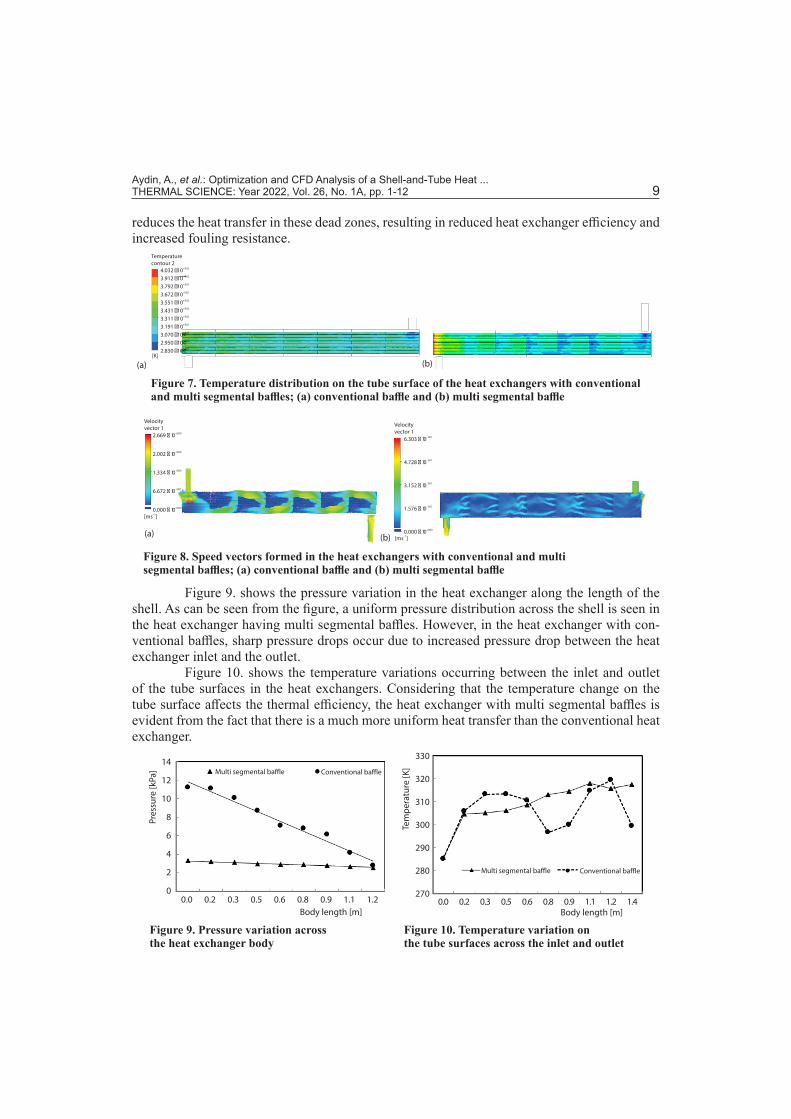
Figure 7 shows the temperature distributions on tube surfaces in heat exchangers hav-ing conventional and multi segmental baffles. As can be seen from the figures, when the curtain multi segmental baffles are used, a much more uniform temperature distribution is obtained on the tube surfaces compared to the conventional situation. This indicates that the heat transfer efficiency of the conventional heat exchanger is lower than multi segmental baffle type heat exchanger.
Figure 8. shows velocity vectors in heat exchangers having conventional and multi segmental baffles. It can be clearly seen from figure that, with the use of the multi segmental baffle, the local turbulence regions occur in the heat exchanger and the velocity distribution is much more homogenous than the conventional heat exchanger. On the other hand, re-circula-tion zones are formed in the back of the baffles in the conventional heat exchanger. In certain local areas of these regions, the speed becomes zero, i.e., the flow becomes stationary. This
Table 5. Measuring ranges and measurement accuracy of the devices used in the experiments and uncertainty levels of the calculated parameters
Equipment Range Accuracy Uncertainty [%]PT 100 0/100 °C ±1 °C
Manometer 0/100 mbar0/2.5 bar
2 mbar0.02 bar
Flow meter 0/50 lt/s 0.01 lt/sHeat transfer rate – – 1.5
Aydin, A., et al.: Optimization and CFD Analysis of a Shell-and-Tube Heat ... THERMAL SCIENCE: Year 2022, Vol. 26, No. 1A, pp. 1-12 9
reduces the heat transfer in these dead zones, resulting in reduced heat exchanger efficiency and increased fouling resistance.
(a) (b)[K]
Temperaturecontour 2
4.032 �10+002
3.912 �10+002
3.792 �10+002
3.672 �10–002
3.551 �10+002
+0023.431 �10+0023.311 �10+0023.191 �10+0023.070 �10+0022.950 �10+0022.830 �10
Figure 7. Temperature distribution on the tube surface of the heat exchangers with conventional and multi segmental baffles; (a) conventional baffle and (b) multi segmental baffle
(a) (b)
2.669 � 10+000
2.002 � 10+000
+0001.334 � 10
+0016.672 � 10
+0000.000 � 10[ms ]–1
[ms ]–1
Velocityvector 1 Velocity
vector 16.303 � 10–001
4.728 � 10–001
–0013.152 � 10
–0011.576 � 10
+0000.000 � 10
Figure 8. Speed vectors formed in the heat exchangers with conventional and multi segmental baffles; (a) conventional baffle and (b) multi segmental baffle
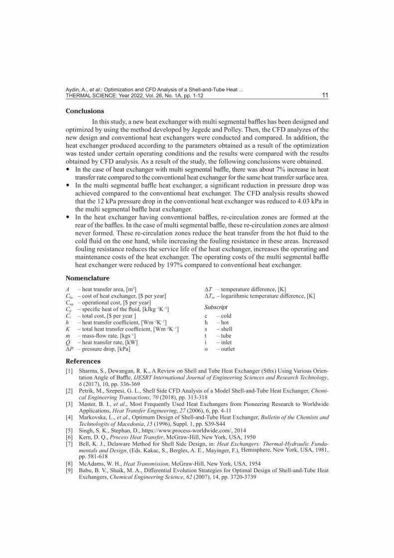
Figure 9. shows the pressure variation in the heat exchanger along the length of the shell. As can be seen from the figure, a uniform pressure distribution across the shell is seen in the heat exchanger having multi segmental baffles. However, in the heat exchanger with con-ventional baffles, sharp pressure drops occur due to increased pressure drop between the heat exchanger inlet and the outlet.
Figure 10. shows the temperature variations occurring between the inlet and outlet of the tube surfaces in the heat exchangers. Considering that the temperature change on the tube surface affects the thermal efficiency, the heat exchanger with multi segmental baffles is evident from the fact that there is a much more uniform heat transfer than the conventional heat exchanger.
Pres
sure
[kPa
]
Body length [m]0.0 0.2 0.3 0.5 0.6 0.8 0.9 1.1 1.2
14
12
10
8
6
4
2
0
Multi segmental baffle Conventional baffle
Multi segmental baffle Conventional baffle
0.0 0.2 0.3 0.5 0.6 0.8 0.9 1.1 1.2 1.4Body length [m]
Tem
pera
ture
[K]
330
320
310
300
290
280
270
Figure 9. Pressure variation across the heat exchanger body
Figure 10. Temperature variation on the tube surfaces across the inlet and outlet

Aydin, A., et al.: Optimization and CFD Analysis of a Shell-and-Tube Heat ... 10 THERMAL SCIENCE: Year 2022, Vol. 26, No. 1A, pp. 1-12
Comparison of the experimental and simulation results
The heat transfer rate calculated by experimental data and the heat transfer rate obtained by CFD analysis in the heat exchanger with multi segmental baffles are compared in fig. 11. As can be seen from the figure, in both cases the heat transfer rate increases as the mass-flow rate increases. A difference up to 9% was occurred between the experimental and the CFD results.
Figure 12 compares the experimental and CFD pressure drops occurring on the tube side of the heat exchanger with multi segmental baffles. As can be seen from the figure, the pressure drops in the tubes increase with the increase of the mass-flow rate as expected. The experimental pressure drops were determined between 0.1-2.0 kPa, and the pressure drop deter-mined with CFD analysis were between 0.09-1.9 kPa. There was a difference up to 8% between the experiment and CFD analysis.
5
10
15
20
25
30
35
40
0 1 2 3 4 5 6
Hea
ttra
nsfe
rrat
e [k
W]
Case
ExperimentCFD
0.0
0.5
1.0
1.5
2.0
2.5
0 1 2 3 4 5 6
Pres
sure
drop
[kPa
]
Case
Experiment
CFD
Figure 11. Heat transfer rate of the heat exchanger for different working conditions
Figure 12. Tube side pressure drop for different working conditions
Table 6 compares CFD analysis results of the optimized multi segmental baffle heat exchanger with the conventional heat exchanger. The results indicate that the new design heat exchanger with multi segmental baffle gives much better results compared to the conventional heat exchanger in terms of both higher heat transfer rate and lower pressure drop. In the case of heat exchanger with multi segmental baffle, there was about 7% increase in heat transfer rate compared to the conventional heat exchanger. In the multi segmental baffle heat exchanger, a significant reduction in pressure drop was achieved compared to the conventional heat ex-changer. The CFD analysis results show that the 12 kPa pressure drop in the conventional heat exchanger was reduced to 4.03 kPa in the multi segmental baffle heat exchanger. Thus, with the use of the multi segmental baffle, the operational cost was reduced 66.42% compared to the conventional baffle.
Table 6. Performance values of the multi segmental and conventional baffle heat exchangers obtained with CFD analyses
Multi segmental baffle Conventional baffleHeat transfer rate [kW] 190 182 Tube outlet temperature [K] 389 390Shell side temperature [K] 300 299Shell side pressure drop [kPa] 4.03 12Tube side pressure drop [kPa] 720 732Heat transfer rate/pressure drop (shell side) [kWk–1Pa–1] 47 15
Aydin, A., et al.: Optimization and CFD Analysis of a Shell-and-Tube Heat ... THERMAL SCIENCE: Year 2022, Vol. 26, No. 1A, pp. 1-12 11
Conclusions
In this study, a new heat exchanger with multi segmental baffles has been designed and optimized by using the method developed by Jegede and Polley. Then, the CFD analyzes of the new design and conventional heat exchangers were conducted and compared. In addition, the heat exchanger produced according to the parameters obtained as a result of the optimization was tested under certain operating conditions and the results were compared with the results obtained by CFD analysis. As a result of the study, the following conclusions were obtained.
y In the case of heat exchanger with multi segmental baffle, there was about 7% increase in heat transfer rate compared to the conventional heat exchanger for the same heat transfer surface area.
y In the multi segmental baffle heat exchanger, a significant reduction in pressure drop was achieved compared to the conventional heat exchanger. The CFD analysis results showed that the 12 kPa pressure drop in the conventional heat exchanger was reduced to 4.03 kPa in the multi segmental baffle heat exchanger.
y In the heat exchanger having conventional baffles, re-circulation zones are formed at the rear of the baffles. In the case of multi segmental baffle, these re-circulation zones are almost never formed. These re-circulation zones reduce the heat transfer from the hot fluid to the cold fluid on the one hand, while increasing the fouling resistance in these areas. Increased fouling resistance reduces the service life of the heat exchanger, increases the operating and maintenance costs of the heat exchanger. The operating costs of the multi segmental baffle heat exchanger were reduced by 197% compared to conventional heat exchanger.
Nomenclature
A – heat transfer area, [m2]Che – cost of heat exchanger, [$ per year]Cop – operational cost, [$ per year]Cp – specific heat of the fluid, [kJkg–1K–1]Ct – total cost, [$ per year ]h – heat transfer coefficient, [Wm–2K–1]K – total heat transfer coefficient, [Wm–2K–1]ṁ – mass-flow rate, [kgs–1]Q̇ – heat transfer rate, [kW]ΔP – pressure drop, [kPa]
ΔT – temperature difference, [K]ΔTm – logarithmic temperature difference, [K]
Subscript
c – coldh – hots – shellt – tubei – inleto – outlet
References[1] Sharma, S., Dewangan, R. K., A Review on Shell and Tube Heat Exchanger (Sthx) Using Various Orien-
tation Angle of Baffle, IJESRT International Journal of Engineering Sciences and Research Technology, 6 (2017), 10, pp. 336-369
[2] Petrik, M., Szepesi, G. L., Shell Side CFD Analysis of a Model Shell-and-Tube Heat Exchanger, Chemi-cal Engineering Transactions, 70 (2018), pp. 313-318
[3] Master, B. I., et al., Most Frequently Used Heat Exchangers from Pioneering Research to Worldwide Applications, Heat Transfer Engineering, 27 (2006), 6, pp. 4-11
[4] Markovska, L., et al., Optimum Design of Shell-and-Tube Heat Exchanger, Bulletin of the Chemists and Technologits of Macedonia, 15 (1996), Suppl. 1, pp. S39-S44
[5] Singh, S. K., Stephan, D., https://www.process-worldwide.com/, 2014[6] Kern, D. Q., Process Heat Transfer, McGraw-Hill, New York, USA, 1950[7] Bell, K. J., Delaware Method for Shell Side Design, in: Heat Exchangers: Thermal-Hydraulic Funda-
mentals and Design, (Eds. Kakac, S., Bergles, A. E., Mayinger, F.), Hemisphere, New York, USA, 1981, pp. 581-618
[8] McAdams, W. H., Heat Transmission, McGraw-Hill, New York, USA, 1954[9] Babu, B. V., Shaik, M. A., Differential Evolution Strategies for Optimal Design of Shell-and-Tube Heat
Exchangers, Chemical Engineering Science, 62 (2007), 14, pp. 3720-3739

Aydin, A., et al.: Optimization and CFD Analysis of a Shell-and-Tube Heat ... 12 THERMAL SCIENCE: Year 2022, Vol. 26, No. 1A, pp. 1-12
[10] Leoni, G. B., et al., Medronho, Assessment with Computational Fluid Dynamics of the Effects of Baffle Clearances on the Shell Side Flow in a Shell and Tube Heat Exchanger, Applied Thermal Engineering, 112 (2017), Feb., pp. 497-506
[11] Ambekar, A. S., et al., The CFD Simulation Study of Shell and Tube Heat Exchangers with Different Baffle Segment Configurations, Applied Thermal Engineering, 108 (2016), Sept., pp. 999-1007
[12] Irshad, M., et al., Design and CFD Analysis of Shell and Tube Heat Exchanger, International Journal of Engineering Science and Computing, 7 (2017), 4, pp. 6453-6457
[13] Ravanagi, M. A. S. S., et al., Optimal Design of Shell-and-Tube Heat Exchangers Using Particle Swarm Optimization, Industrial and Engineering Chemıstry Research, 48 (2009), 6, pp. 2927-2935
[14] Abd, A. A., Naji, S. Z., Analysis Study of Shell and Tube Heat Exchanger for Clough Company with Reselect Different Parameters to Improve the Design, Case Studies in Thermal Engineering, 10 (2017), Sept., pp. 455-467
[15] Bhandurge, S. R., et al., Analysis and Experimentation of Shell and Tube Heat Exchanger with Different Orientation of Baffles, International Journal for Research in Applied Science and Engineering Technol-ogy, 4 (2016), 6, pp. 490-503
[16] Edwards, J. E., Design and Rating Shell and Tube Heat Exchanger, Teesside University, Teesside, UK, 2008
[17] Ponce, J. M., et al., Optimal Design of Shell-and-Tube Heat Exchangers Using Genetic Algorithms, 16th
European Symposium on Computer Aided Process Engineering and 9th International Symposium on Pro-cess Systems Engineering, Elsevier, Amsterdam, The Netherlands, 2006, Vol. 21, pp. 985-990
[18] Varga, T., et al., Horizontal Scraped Surface Heat Exchanger – Experimental Measurements and Numer-ical Analysis, Pollack Periodica, 12 (2017), 1, pp. 107-122
[19] Azad, A. V., Amidpour, M., Economic Optimization of Shell and Tube Heat Exchanger Based on Con-structal Theory, Energy, 36 (2011), 2, pp. 1087-1096
[20] Shrikant, A. A., et al., Comparison of Shell and Tube Heat Exchanger using Theoretical Methods, HTRI, ASPEN and SOLIDWORKS Simulation Softwares, Int. Journal of Engineering Research and Applica-tion, 6 (2016), Mar., pp. 99-107
[21] Sanaye, S., Hajabdollahi, H., Multi-Objective Optimization of Shell and Tube Heat Exchangers, Applied Thermal Engineering, 30 (2010), 14-15, pp. 1937-1945
[22] Jegede, F. O., Polley, G. T., Optimum Heat-Exchanger Design, Chemical Engineerıng Research & De-sign, 70 (1992), Nov., pp. 133-141
[23] Engin, T., Gungor, K. E., Design and Cost of Shell-Tube Heat Exchangers Optimization by Parameters (in Turkish), TÜBİTAK-Türk Mühendislik ve Çevre Bilimleri Dergisi, 20 (1996), pp. 313-322
[24] Turchi, A., et al., Thermochemical Ablation Modelling Forward Uncertainty Analysis – Part II: Ap-plication Plasma Wind-Tunnel Testing, International Journal of Thermal Sciences, 118 (2017), Aug., pp. 510-517
Paper submitted: February 22, 2020Paper revised: September 7, 2020Paper accepted: September 16, 2020
© 2022 Society of Thermal Engineers of SerbiaPublished by the Vinča Institute of Nuclear Sciences, Belgrade, Serbia.
This is an open access article distributed under the CC BY-NC-ND 4.0 terms and conditions