optimizing central chilled water systems · • hydronic system design • chiller fundamentals ......
TRANSCRIPT

1 O P T I M I Z I N G C E N T R A L C H I L L E D W A T E R S Y S T E M S 1 O P T I M I Z I N G C E N T R A L C H I L L E D W A T E R S Y S T E M S
Optimizing Central Chilled Water Systems
Kent W. Peterson, PE, FASHRAE P2S Engineering, Inc. [email protected]

2 O P T I M I Z I N G C E N T R A L C H I L L E D W A T E R S Y S T E M S 2 O P T I M I Z I N G C E N T R A L C H I L L E D W A T E R S Y S T E M S 2
Learning Objectives
1. Gain a better understanding of the operational dynamics of various load and equipment components in chilled water systems
2. Understand opportunities to provide both functional and energy efficient operation of chilled water systems
3. Develop a logical approach to the performance optimization of chilled water systems
3 O P T I M I Z I N G C E N T R A L C H I L L E D W A T E R S Y S T E M S 3 O P T I M I Z I N G C E N T R A L C H I L L E D W A T E R S Y S T E M S
Presentation Outline
• Foundation of CHW Plant Operation
• Hydronic System Design
• Chiller Fundamentals
• Optimizing Plant Performance
• Building Interfaces
3

4 O P T I M I Z I N G C E N T R A L C H I L L E D W A T E R S Y S T E M S 4 O P T I M I Z I N G C E N T R A L C H I L L E D W A T E R S Y S T E M S
Sustainability Opportunities
• Optimize energy use
• Protect and conserve water
• Effective use of natural resources
4

5 O P T I M I Z I N G C E N T R A L C H I L L E D W A T E R S Y S T E M S 5 O P T I M I Z I N G C E N T R A L C H I L L E D W A T E R S Y S T E M S
Foundation of Operation
• Why look “outside the plant”? - Understand how distribution system will operate - Understand how CHW ∆T will be effected by
dynamics of the systems connected
Deliver CHW to all loads under various load conditions as efficiently as possible
5

6 O P T I M I Z I N G C E N T R A L C H I L L E D W A T E R S Y S T E M S 6 O P T I M I Z I N G C E N T R A L C H I L L E D W A T E R S Y S T E M S
Understanding Loads & Their Impact on Design
• Overall plant capacity is determined by peak design load
• Cooling load profile describes how the load varies over time is needed to design the plant to stage efficiently
• Cooling load “diversity”
6
7 O P T I M I Z I N G C E N T R A L C H I L L E D W A T E R S Y S T E M S 7 O P T I M I Z I N G C E N T R A L C H I L L E D W A T E R S Y S T E M S
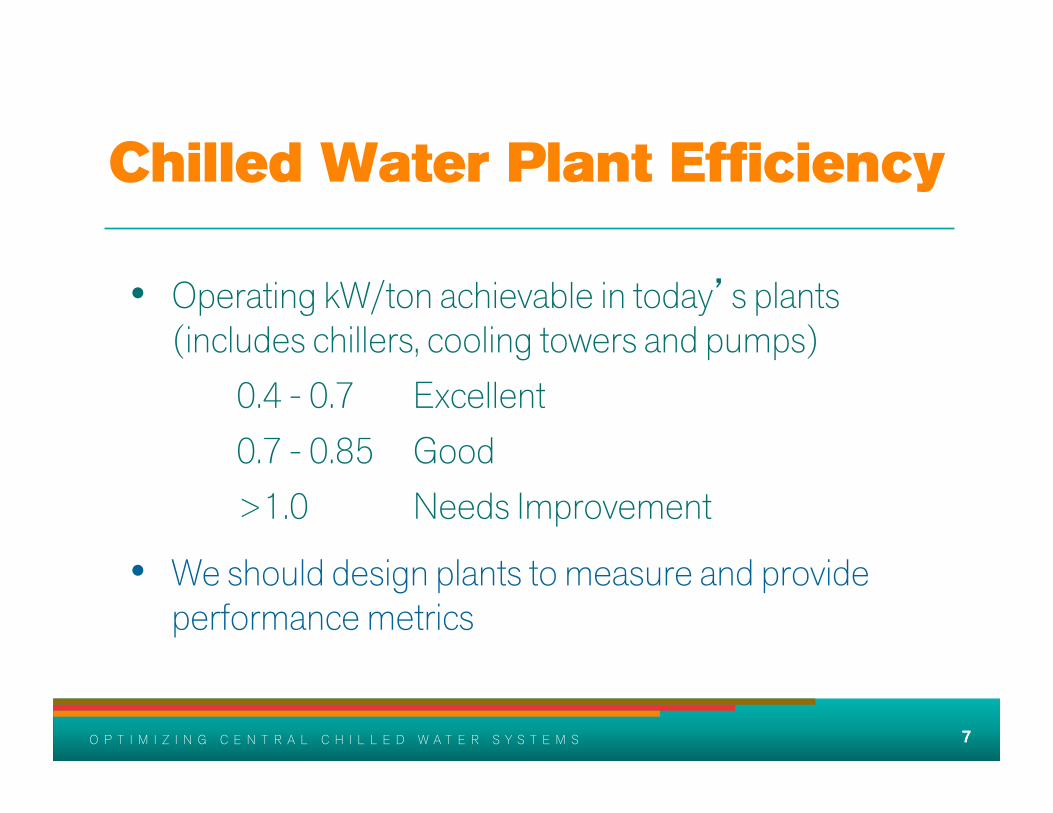
Chilled Water Plant Efficiency
• Operating kW/ton achievable in today’s plants (includes chillers, cooling towers and pumps)
• 0.4 - 0.7 Excellent • 0.7 - 0.85 Good • >1.0 Needs Improvement
• We should design plants to measure and provide performance metrics
7

8 O P T I M I Z I N G C E N T R A L C H I L L E D W A T E R S Y S T E M S 8 O P T I M I Z I N G C E N T R A L C H I L L E D W A T E R S Y S T E M S
Discussion on Hydronics
8
9 O P T I M I Z I N G C E N T R A L C H I L L E D W A T E R S Y S T E M S 9 O P T I M I Z I N G C E N T R A L C H I L L E D W A T E R S Y S T E M S
Purpose of Pumping Systems
Move enough water through the piping system at the minimum differential pressure
that will satisfy all connected loads
9
10 O P T I M I Z I N G C E N T R A L C H I L L E D W A T E R S Y S T E M S 10 O P T I M I Z I N G C E N T R A L C H I L L E D W A T E R S Y S T E M S
Understanding Hydronics
• The pumping system will be required to operate under various load conditions
• Variable flow system differential pressures throughout the system will be dynamic
• Hydronic systems should be hydraulically modeled to design or troubleshoot complex systems
10

11 O P T I M I Z I N G C E N T R A L C H I L L E D W A T E R S Y S T E M S 11 O P T I M I Z I N G C E N T R A L C H I L L E D W A T E R S Y S T E M S
Caution
• Excessive pump head can cause systems to not function as designed and waste considerable energy
• Pump Selection

12 O P T I M I Z I N G C E N T R A L C H I L L E D W A T E R S Y S T E M S 12 O P T I M I Z I N G C E N T R A L C H I L L E D W A T E R S Y S T E M S
System & Pump Curves
Total Flow
Tota
l Pre
ssur
e
12
0
50
100
150
200
250
300
0 1500 3000 4500 6000 7500 9000 10500 12000
S ystem Curve Combined Pump Curve
13 O P T I M I Z I N G C E N T R A L C H I L L E D W A T E R S Y S T E M S 13 O P T I M I Z I N G C E N T R A L C H I L L E D W A T E R S Y S T E M S
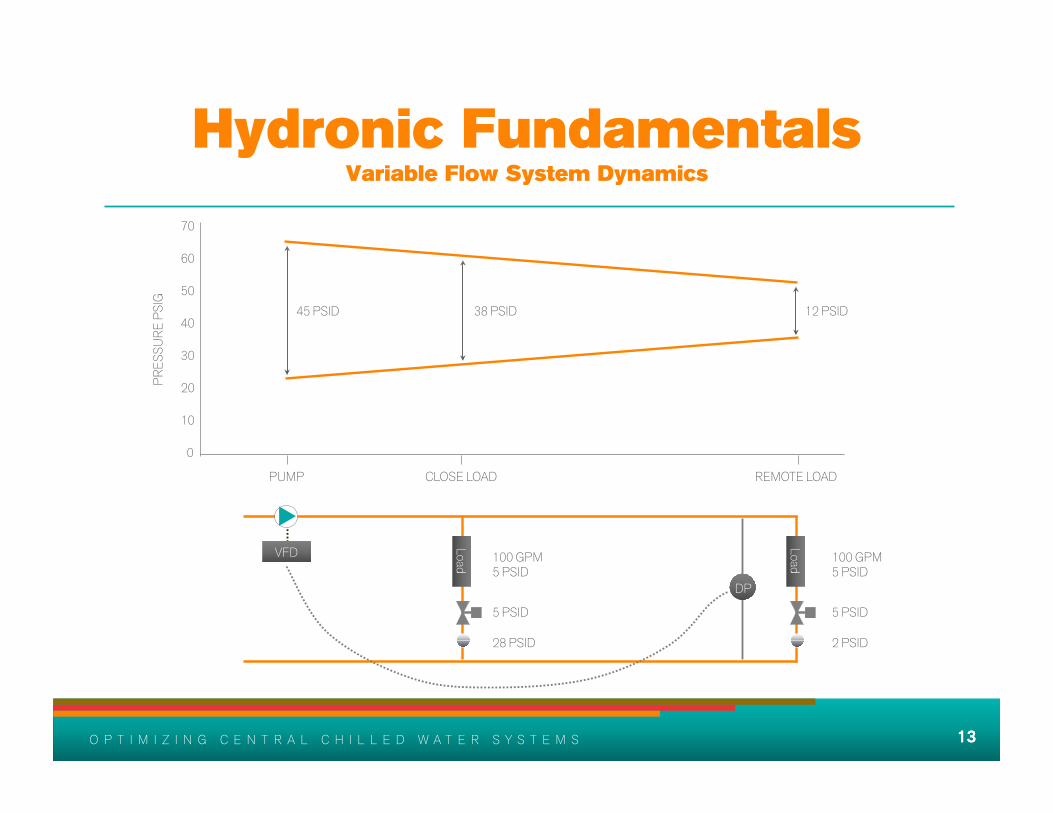
Hydronic Fundamentals Variable Flow System Dynamics
VFD
Load DP
100 GPM 5 PSID
100 GPM 5 PSID
5 PSID 28 PSID
5 PSID 2 PSID
12 PSID 38 PSID 45 PSID
PUMP CLOSE LOAD REMOTE LOAD
20
60
50
40
30
10
0
70
PRES
SURE
PSI
G
13
Load

14 O P T I M I Z I N G C E N T R A L C H I L L E D W A T E R S Y S T E M S 14 O P T I M I Z I N G C E N T R A L C H I L L E D W A T E R S Y S T E M S
Hydronic Fundamentals Variable Flow System Dynamics
VFD
DP
100 GPM 5 PSID
0 GPM 0 PSID
5 PSID 28 PSID
38 PSID 0 PSID
BAD SENSOR LOCATION
38 PSID 38 PSID 45 PSID
PUMP CLOSE LOAD REMOTE LOAD
20
60
50
40
30
10
0
70
PRES
SURE
PSI
G
14
Load
Load
15 O P T I M I Z I N G C E N T R A L C H I L L E D W A T E R S Y S T E M S 15 O P T I M I Z I N G C E N T R A L C H I L L E D W A T E R S Y S T E M S
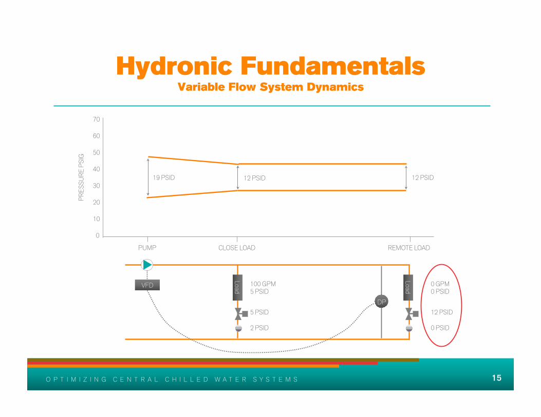
Hydronic Fundamentals Variable Flow System Dynamics
100 GPM 5 PSID
0 GPM 0 PSID
5 PSID 2 PSID
12 PSID 0 PSID
12 PSID 12 PSID 19 PSID
PUMP CLOSE LOAD REMOTE LOAD
20
60
50
40
30
10
0
70
PRES
SURE
PSI
G
VFD
Load
DP Load
16 O P T I M I Z I N G C E N T R A L C H I L L E D W A T E R S Y S T E M S 16 O P T I M I Z I N G C E N T R A L C H I L L E D W A T E R S Y S T E M S
Hydronic Fundamentals Variable Flow System Dynamics
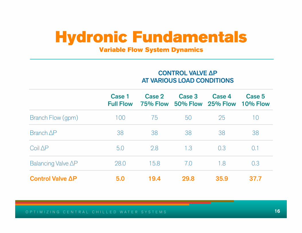
CONTROL VALVE ∆P AT VARIOUS LOAD CONDITIONS
Case 1 Full Flow
Case 2 75% Flow
Case 3 50% Flow
Case 4 25% Flow
Case 5 10% Flow
Branch Flow (gpm) 100 75 50 25 10
Branch ∆P 38 38 38 38 38
Coil ∆P 5.0 2.8 1.3 0.3 0.1
Balancing Valve ∆P 28.0 15.8 7.0 1.8 0.3
Control Valve ∆P 5.0 19.4 29.8 35.9 37.7
16
17 O P T I M I Z I N G C E N T R A L C H I L L E D W A T E R S Y S T E M S 17 O P T I M I Z I N G C E N T R A L C H I L L E D W A T E R S Y S T E M S
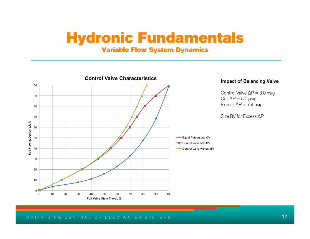
Hydronic Fundamentals Variable Flow System Dynamics
Impact of Balancing Valve Control Valve ∆P = 3.0 psig Coil ∆P = 5.0 psig Excess ∆P = 7.4 psig Size BV for Excess ∆P

18 O P T I M I Z I N G C E N T R A L C H I L L E D W A T E R S Y S T E M S 18 O P T I M I Z I N G C E N T R A L C H I L L E D W A T E R S Y S T E M S
Balancing Considerations Variable Flow Systems
• Too large a balancing valve pressure drop affects the performance and flow characteristic of the control valve. Too small a pressure drop affects its flow measurement accuracy as it is closed to balance the system. - ASHRAE 2011 Applications Handbook, page 38.8

19 O P T I M I Z I N G C E N T R A L C H I L L E D W A T E R S Y S T E M S 19 O P T I M I Z I N G C E N T R A L C H I L L E D W A T E R S Y S T E M S
Hydronic Pumping Conclusions
• Coil heat transfer is easier to control in low head (<50 ft) branches
• Remote, high head loads can be served more efficiently with variable speed series booster pumping

20 O P T I M I Z I N G C E N T R A L C H I L L E D W A T E R S Y S T E M S 20 O P T I M I Z I N G C E N T R A L C H I L L E D W A T E R S Y S T E M S
What You Must Know About
CHW ∆T
20
21 O P T I M I Z I N G C E N T R A L C H I L L E D W A T E R S Y S T E M S 21 O P T I M I Z I N G C E N T R A L C H I L L E D W A T E R S Y S T E M S
CHW Temperature Differential
• Poor CHW ∆T is the largest contributor to poor CHW plant performance
• To predict ∆T, you must know: - Characteristics of connected loads - Control valve requirements and limitations - Control valve control algorithms and set points - Heat exchanger characteristics
22 O P T I M I Z I N G C E N T R A L C H I L L E D W A T E R S Y S T E M S 22 O P T I M I Z I N G C E N T R A L C H I L L E D W A T E R S Y S T E M S
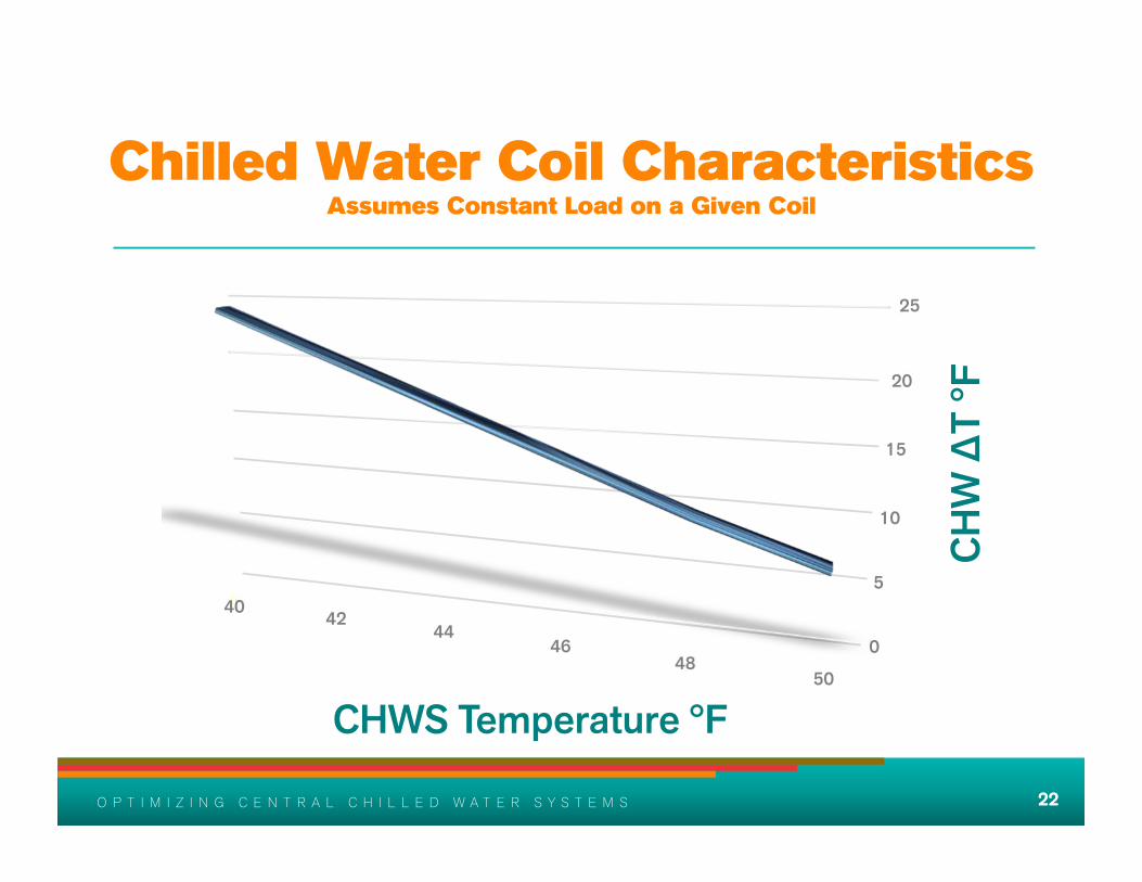
Chilled Water Coil Characteristics Assumes Constant Load on a Given Coil
22
CHWS Temperature °F
CHW
∆T
°F
40 42 44
46 48
50
0
5
10
15
20
25
23 O P T I M I Z I N G C E N T R A L C H I L L E D W A T E R S Y S T E M S 23 O P T I M I Z I N G C E N T R A L C H I L L E D W A T E R S Y S T E M S
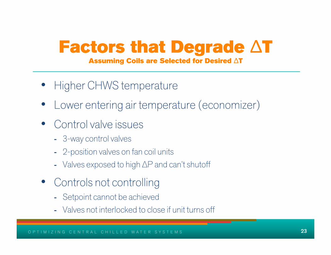
Factors that Degrade ∆T Assuming Coils are Selected for Desired ∆T
• Higher CHWS temperature
• Lower entering air temperature (economizer)
• Control valve issues - 3-way control valves - 2-position valves on fan coil units - Valves exposed to high ∆P and can’t shutoff
• Controls not controlling - Setpoint cannot be achieved - Valves not interlocked to close if unit turns off

24 O P T I M I Z I N G C E N T R A L C H I L L E D W A T E R S Y S T E M S 24 O P T I M I Z I N G C E N T R A L C H I L L E D W A T E R S Y S T E M S
∆T Conclusions
• Design, construction and operation errors that cause low ∆T can be avoided
• Other causes for low ∆T can never be eliminated
• Therefore, system design must accommodate the level of degradation anticipated

25 O P T I M I Z I N G C E N T R A L C H I L L E D W A T E R S Y S T E M S 25 O P T I M I Z I N G C E N T R A L C H I L L E D W A T E R S Y S T E M S
Chiller Fundamentals
25

26 O P T I M I Z I N G C E N T R A L C H I L L E D W A T E R S Y S T E M S 26 O P T I M I Z I N G C E N T R A L C H I L L E D W A T E R S Y S T E M S
Understanding Compressor Lift
• Temperature Lift = SCT - SST - Saturated Condensing Temperature (SCT) is
dependent upon LEAVING condenser water temperature
- Saturated Suction Temperature (SST) is based off of LEAVING chilled water temperature

27 O P T I M I Z I N G C E N T R A L C H I L L E D W A T E R S Y S T E M S 27 O P T I M I Z I N G C E N T R A L C H I L L E D W A T E R S Y S T E M S
Percent Loaded
KW/t
on
Centrifugal Chiller without VFD 1200T Low Pressure
0.2
0.4
0.6
0.8
1.0
25 50 75 100
65 ECWT 75 ECWT 85 ECWT
28 O P T I M I Z I N G C E N T R A L C H I L L E D W A T E R S Y S T E M S 28 O P T I M I Z I N G C E N T R A L C H I L L E D W A T E R S Y S T E M S
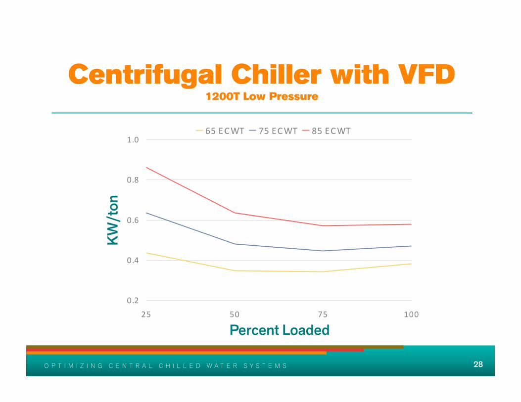
Centrifugal Chiller with VFD 1200T Low Pressure
0.2
0.4
0.6
0.8
1.0
25 50 75 100
65 ECWT 75 ECWT 85 ECWT
Percent Loaded
KW/t
on

29 O P T I M I Z I N G C E N T R A L C H I L L E D W A T E R S Y S T E M S 29 O P T I M I Z I N G C E N T R A L C H I L L E D W A T E R S Y S T E M S
0.2
0.4
0.6
0.8
1.0
25 50 75 100
65 ECWT 75 ECWT 85 ECWT
Centrifugal Chiller without VFD 1200T High Pressure
Percent Loaded
KW/t
on

30 O P T I M I Z I N G C E N T R A L C H I L L E D W A T E R S Y S T E M S 30 O P T I M I Z I N G C E N T R A L C H I L L E D W A T E R S Y S T E M S
Centrifugal Chiller with VFD 1200T High Pressure
0.2
0.4
0.6
0.8
1.0
25 50 75 100
65 ECWT 75 ECWT 85 ECWT
Percent Loaded
KW/t
on
31 O P T I M I Z I N G C E N T R A L C H I L L E D W A T E R S Y S T E M S 31 O P T I M I Z I N G C E N T R A L C H I L L E D W A T E R S Y S T E M S
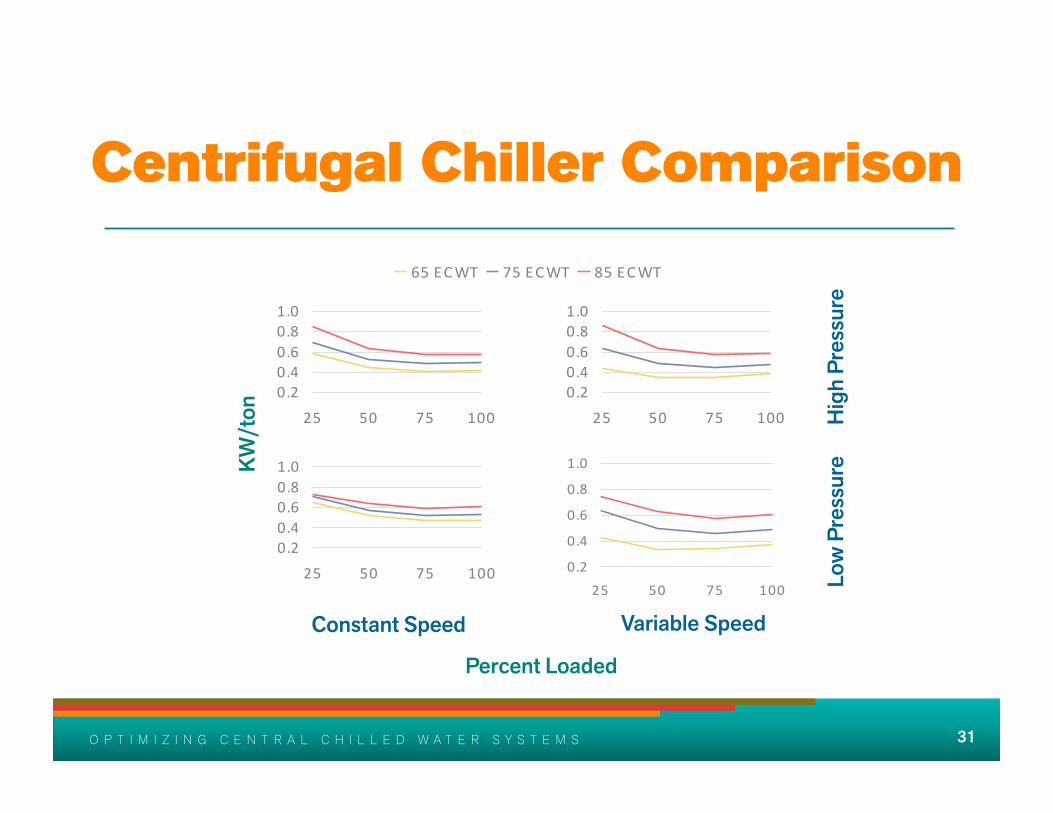
Centrifugal Chiller Comparison
0.2
0.4
0.6
0.8
1.0
25 50 75 100
65 ECWT 75 ECWT 85 ECWT
Percent Loaded
KW/t
on
0.20.40.60.81.0
25 50 75 100
0.20.40.60.81.0
25 50 75 100
0.20.40.60.81.0
25 50 75 100 Hig
h Pr
essu
re
Low
Pre
ssur
e
Constant Speed Variable Speed

32 O P T I M I Z I N G C E N T R A L C H I L L E D W A T E R S Y S T E M S 32 O P T I M I Z I N G C E N T R A L C H I L L E D W A T E R S Y S T E M S
Centrifugal Chiller with VFD 1000T High Pressure, Multiple Oil-Free Compressors
0.2
0.4
0.6
0.8
1.0
25 50 75 100
65 ECWT 75 ECWT 85 ECWT
Percent Loaded
KW/t
on

33 O P T I M I Z I N G C E N T R A L C H I L L E D W A T E R S Y S T E M S 33 O P T I M I Z I N G C E N T R A L C H I L L E D W A T E R S Y S T E M S
Optimizing Plant Performance

34 O P T I M I Z I N G C E N T R A L C H I L L E D W A T E R S Y S T E M S 34 O P T I M I Z I N G C E N T R A L C H I L L E D W A T E R S Y S T E M S
Primary-Secondary vs Variable Primary Flow
• Variable primary flow plants can provide advantages over traditional primary-secondary configurations
• Less plant space required for VPF
• VPF is not conducive to CHW Thermal Energy Storage

35 O P T I M I Z I N G C E N T R A L C H I L L E D W A T E R S Y S T E M S 35 O P T I M I Z I N G C E N T R A L C H I L L E D W A T E R S Y S T E M S
Primary-Secondary Variable Flow Part Load Operation - 4500 Ton Plant
Load
58°F
42°F VFD
∆P
6000 GPM 4500 GPM
1500 GPM
42°F
54°F
1500 tons
1500 tons
OFF
Load
Load
Load
Load

36 O P T I M I Z I N G C E N T R A L C H I L L E D W A T E R S Y S T E M S 36 O P T I M I Z I N G C E N T R A L C H I L L E D W A T E R S Y S T E M S
Primary-Secondary Variable Flow Effect of Low CHWR Temperature
Low ∆T Syndrome
44°F
52°F
42°F
6000 GPM 9000 GPM
3000 GPM
Additional chiller will need to be started to maintain the secondary CHWS temperature setpoint if load increases
Loss of CHWS temp control
Load
Load
Load
Load
Load VFD
∆P 1500 tons
1500 tons
OFF 52°F
37 O P T I M I Z I N G C E N T R A L C H I L L E D W A T E R S Y S T E M S 37 O P T I M I Z I N G C E N T R A L C H I L L E D W A T E R S Y S T E M S
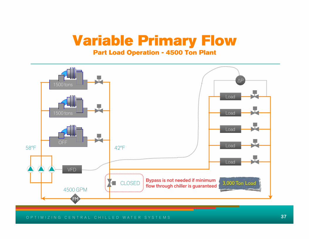
Variable Primary Flow Part Load Operation - 4500 Ton Plant
42°F
CLOSED
58°F
4500 GPM FM
Bypass is not needed if minimum flow through chiller is guaranteed
1500 tons
1500 tons
OFF
∆P
Load
Load
Load
Load
Load VFD
38 O P T I M I Z I N G C E N T R A L C H I L L E D W A T E R S Y S T E M S 38 O P T I M I Z I N G C E N T R A L C H I L L E D W A T E R S Y S T E M S
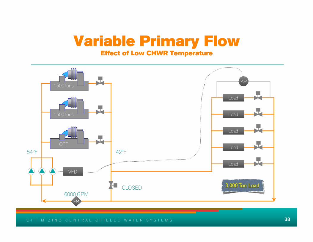
Variable Primary Flow Effect of Low CHWR Temperature
CLOSED
54°F
6000 GPM
42°F
1500 tons
1500 tons
OFF
∆P
Load
Load
Load
Load
Load VFD
FM
39 O P T I M I Z I N G C E N T R A L C H I L L E D W A T E R S Y S T E M S 39 O P T I M I Z I N G C E N T R A L C H I L L E D W A T E R S Y S T E M S
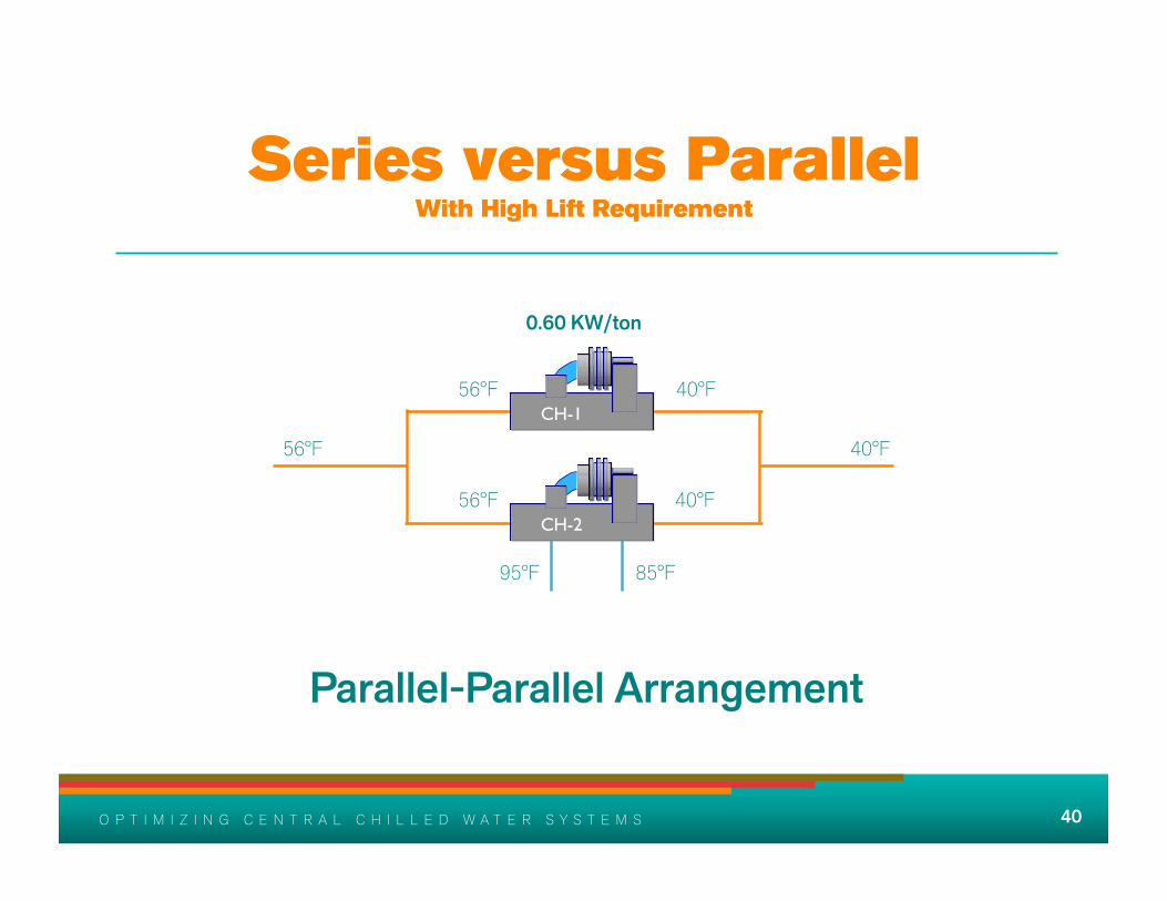
Series Arrangement
• In applications with high lift, a series evaporator arrangement can improve overall plant performance
40 O P T I M I Z I N G C E N T R A L C H I L L E D W A T E R S Y S T E M S 40 O P T I M I Z I N G C E N T R A L C H I L L E D W A T E R S Y S T E M S
85°F 95°F
40°F 56°F CH-1
CH-2 40°F 56°F
40°F 56°F
0.60 KW/ton
Parallel-Parallel Arrangement
Series versus Parallel With High Lift Requirement

41 O P T I M I Z I N G C E N T R A L C H I L L E D W A T E R S Y S T E M S 41 O P T I M I Z I N G C E N T R A L C H I L L E D W A T E R S Y S T E M S
7% KW Reduction on Chillers or
450 KW Reduction on 10,000 ton Plant
30 feet head increase on condenser water would
result in 230 KW increase in pump power
220
Series versus Parallel With High Lift Requirement
CH-1 CH-2
95°F 85°F 90°F
0.52 KW/ton 0.59 KW/ton
0.555 KW/ton
Series-Counterflow Arrangement
40°F 56°F 48°F

42 O P T I M I Z I N G C E N T R A L C H I L L E D W A T E R S Y S T E M S 42 O P T I M I Z I N G C E N T R A L C H I L L E D W A T E R S Y S T E M S
CH-1 CH-2 40°F 56°F 48°F
0.50 KW/ton 0.61 KW/ton
7% KW Reduction or
450 KW Reduction on 10,000 ton Plant
0.555 KW/ton
Series-Parallel Arrangement
85°F 95°F 85°F 95°F
Series versus Parallel With High Lift Requirement
43 O P T I M I Z I N G C E N T R A L C H I L L E D W A T E R S Y S T E M S 43 O P T I M I Z I N G C E N T R A L C H I L L E D W A T E R S Y S T E M S
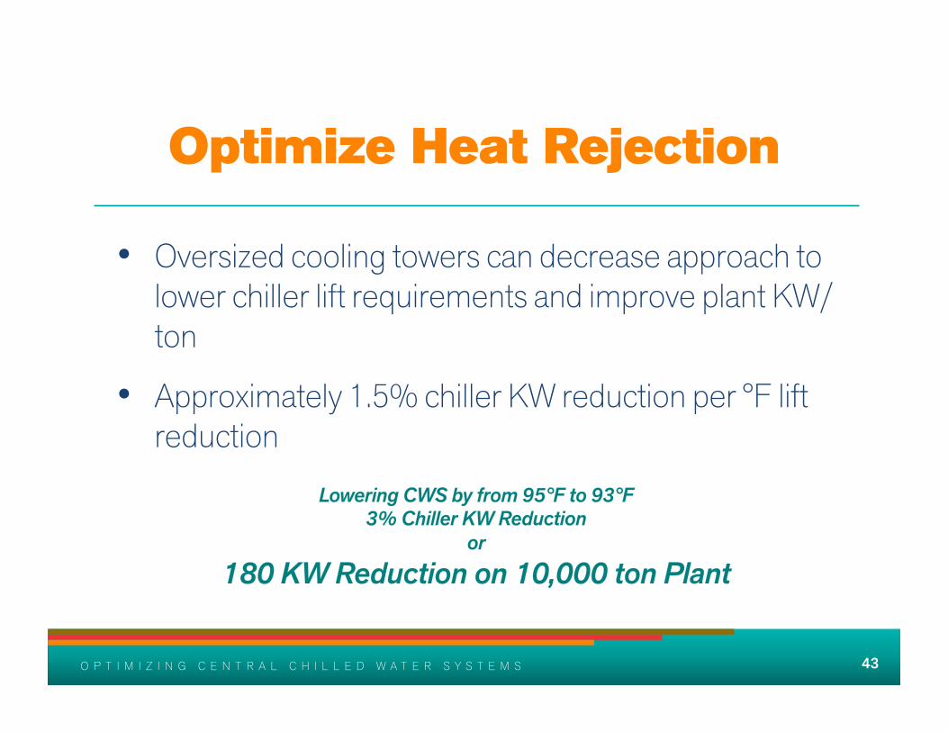
Optimize Heat Rejection
• Oversized cooling towers can decrease approach to lower chiller lift requirements and improve plant KW/ton
• Approximately 1.5% chiller KW reduction per °F lift reduction
Lowering CWS by from 95°F to 93°F 3% Chiller KW Reduction
or 180 KW Reduction on 10,000 ton Plant

44 O P T I M I Z I N G C E N T R A L C H I L L E D W A T E R S Y S T E M S 44 O P T I M I Z I N G C E N T R A L C H I L L E D W A T E R S Y S T E M S
CHW ∆T
Option 1 40°F 56°F 16°F
10,000 tons 15,000 gpm
200 feet head 667
38% Pump KW Reduction or
254 KW Reduction on 10,000 ton Plant
Option 2 38°F 58°F 20°F
10,000 tons 12,000 gpm
146 feet head 413
CHWS Temp CHWR Temp CHW ∆T Plant Size CHW Flow Head Pump KW
87
Increased chiller lift would result in 167
KW increase in chiller power

45 O P T I M I Z I N G C E N T R A L C H I L L E D W A T E R S Y S T E M S 45 O P T I M I Z I N G C E N T R A L C H I L L E D W A T E R S Y S T E M S
Thermal Energy Storage
• Chilled water thermal storage is a viable means of reducing peak electrical demand and increasing plant efficiency
• Less chiller and cooling tower capacity required
• You may qualify for a Permanent Load Shift incentive
• Keep it simple!

46 O P T I M I Z I N G C E N T R A L C H I L L E D W A T E R S Y S T E M S 46 O P T I M I Z I N G C E N T R A L C H I L L E D W A T E R S Y S T E M S
Building Interface Considerations
47 O P T I M I Z I N G C E N T R A L C H I L L E D W A T E R S Y S T E M S 47 O P T I M I Z I N G C E N T R A L C H I L L E D W A T E R S Y S T E M S
Building Interface Considerations Energy Transfer Stations Using Heat Exchangers
• Heat exchangers designed with lower approaches will typically yield higher CHW ∆T
• Always focus on supplying load with proper CHWS temperature

48 O P T I M I Z I N G C E N T R A L C H I L L E D W A T E R S Y S T E M S 48 O P T I M I Z I N G C E N T R A L C H I L L E D W A T E R S Y S T E M S
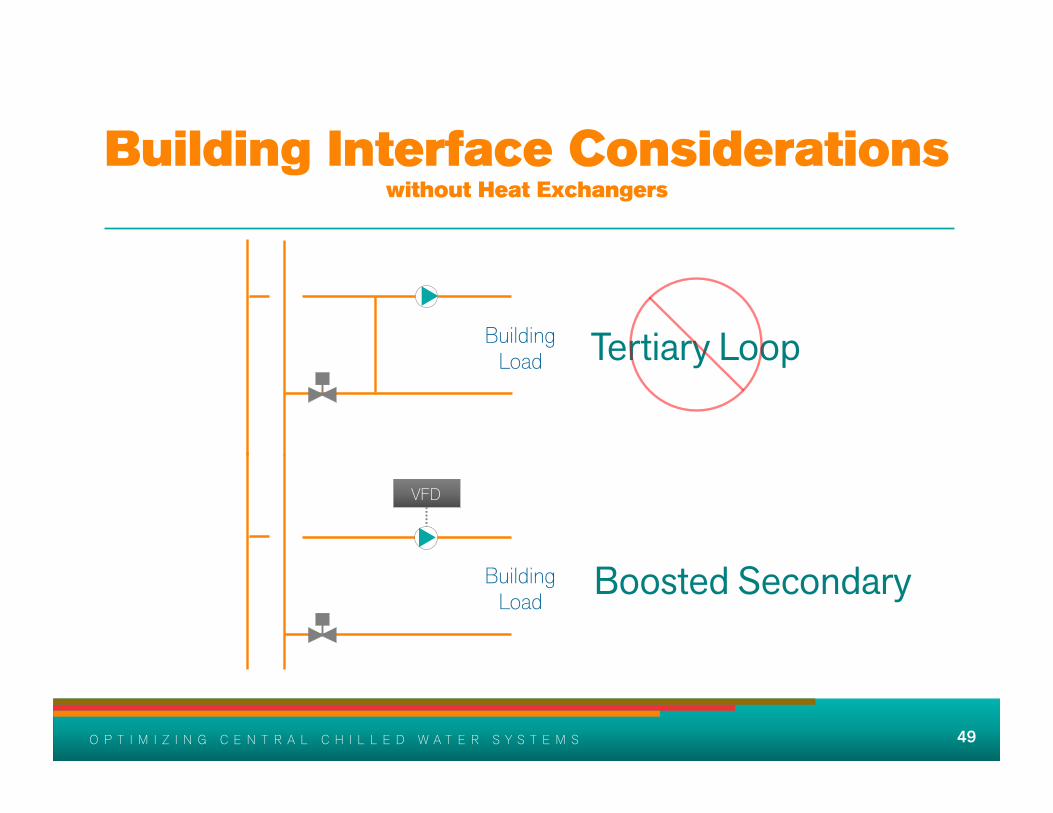
Building Interface Considerations without Heat Exchangers
• Avoid chilled water tertiary loops - Remember cooling coil fundamentals
• A variable speed booster pump should be used to boost differential pressure when needed
49 O P T I M I Z I N G C E N T R A L C H I L L E D W A T E R S Y S T E M S 49 O P T I M I Z I N G C E N T R A L C H I L L E D W A T E R S Y S T E M S
Building Interface Considerations without Heat Exchangers
Building Load Tertiary Loop
Building Load
VFD
Boosted Secondary
50 O P T I M I Z I N G C E N T R A L C H I L L E D W A T E R S Y S T E M S 50 O P T I M I Z I N G C E N T R A L C H I L L E D W A T E R S Y S T E M S
A Case for Metering
• Most efficiently designed systems are horribly inefficient after several years of operation
• How can we improve operation if we don’t evaluate the efficiency?
• Calibrate regularly
51 O P T I M I Z I N G C E N T R A L C H I L L E D W A T E R S Y S T E M S 51 O P T I M I Z I N G C E N T R A L C H I L L E D W A T E R S Y S T E M S
A Case for Commissioning
• Commissioning is a systematic process of assuring that systems perform in accordance with the design intent and owner’s operational needs
• Retro-commissioning

52 O P T I M I Z I N G C E N T R A L C H I L L E D W A T E R S Y S T E M S 52 O P T I M I Z I N G C E N T R A L C H I L L E D W A T E R S Y S T E M S
Control Design Issues
• Control strategies should consider impact on complete system
• Aim to continually optimize energy efficiency for entire system - Demand control - Relational control
• Aim for reliability and “simplicity”
53 O P T I M I Z I N G C E N T R A L C H I L L E D W A T E R S Y S T E M S 53 O P T I M I Z I N G C E N T R A L C H I L L E D W A T E R S Y S T E M S
Summary
• Understand parameters that affect chiller plant and overall system performance
• Optimize operation through equipment selection and control sequences to deliver CHW to all loads as efficiently as possible throughout the year
• Commission and monitor plant performance

54 O P T I M I Z I N G C E N T R A L C H I L L E D W A T E R S Y S T E M S 54 O P T I M I Z I N G C E N T R A L C H I L L E D W A T E R S Y S T E M S
If you are not prepared to be wrong, you won’t come up with
anything original
55 O P T I M I Z I N G C E N T R A L C H I L L E D W A T E R S Y S T E M S 55 O P T I M I Z I N G C E N T R A L C H I L L E D W A T E R S Y S T E M S
For More Information
• ASHRAE Self Directed Learning Course “Fundamentals of Water System Design”
• ASHRAE District Cooling Guide, 2013
• ASHRAE Journal series “Optimizing Chilled Water Plants”
• Hydronic System Design & Operation by E.G. Hansen

56 O P T I M I Z I N G C E N T R A L C H I L L E D W A T E R S Y S T E M S 56 O P T I M I Z I N G C E N T R A L C H I L L E D W A T E R S Y S T E M S
Thank You