orange2014 - igvc.org
TRANSCRIPT

HOSEI UNIVERSITY
Orange2014
Design Report
Hironobu Kariya, Kentaro Ueno, Tomoya Yoshida, Hideyuki Saito, Kazuki Ito, Mikito
Takahashi, Yoshitaka Fukuda, Shinnosuke Tokuda, Kazuki Fukuda and Yosuke Takebayashi
May 9, 2014
Faculty Advisor Statement
I hereby certify that the engineering design on Orange2014 was done by the current student
team and has been significant and equivalent to what might be awarded credit in a senior
design course.
Signed Date
Prof. Kazuyuki Kobayashi May 9,2014
Prof. Rebbeca Erwin Fukuzawa
Prof. Kazuyuki Kobayashi
Faculty of Science and Engineering, Hosei University
3-7-2 Kajinocho Koganei, Tokyo 194-8584, Japan
E-mail; [email protected]
1
ORANGE2014
Hosei University
Hironobu Kariya, Kentaro Ueno, Tomoya Yoshida, Hideyuki Saito, Kazuki Ito, Mikito Takahashi, Yoshitaka Fukuda, Shinnosuke Tokuda,
Kazuki Fukuda and Yosuke Takebayashi
Kazuyuki Kobayashi & [email protected] Rebbeca Erwin Fukuzawa & [email protected]
ABSTRACT
This paper describes the development of Orange2014 for participation in
IGVC2014. Orange2014 is basically built on the basis of Orange2013, which
participated in last year’s IGVC. The authors’ team achieved second place in the
overall judgment, fourth in the Auto-Nav Challenge, and first in JAUS Challenge.
Based on the experiences gained from the failures encountered in the last year’s
competition, we have reviewed the shortcomings of Orange 2013 and redesigned
Orange2014 with overall improvement in performance.
INTRODUCTION
The Autonomous Robotics Laboratory research team of Hosei University has redesigned and
amended both the hardware and software of Orange2014 based on the team discussions to
implement the new concept of “dependability” for IGVC 2014. Dependability is a measure of a
system’s availability, reliability, and maintainability. This also encompasses the mechanisms
designed to increase and maintain the dependability of a system. Based on the experiences gained
from the failures and shortcomings of IGVC 2013, it is believed that such concepts are very
important for designing the autonomous mobile robot.
A summary of the failures and shortcomings of Orange2013 from the viewpoint of
dependability is presented in Figure 1. This paper provides a detailed explanation of the problems
that need to be circumvented in this regard.
IGVC2014-ORANGE2014

2
Figure 1. Schematic depicting the shortcomings of Orange2013 and the suggested improvements in
Orange2014 in terms of both software and hardware
Table 1. Problems associated with Orange2013 and the corresponding solutions for
circumventing the shortcomings, as proposed in Orange2014
Problem Solution
Low resolution of the Omnidirectional camera. To improve the resolution par grid of the straight
lane pixels in omnidirectional image, the camera is
rotated 45° with respect to the yaw axis.
Line detection failed because of the color tone
change in the Omnidirectional camera image.
The brightness of the image is corrected, signifying
the observation of the color patch.
3D LIDAR failed to detect the fence owing to the
extreme thinness of the fence.
The fence is detected using the Omnidirectional
camera.
3D LIDAR was sensitive to rain. A waterproof 3D LIDAR is reconstructed.
The glass of the Omnidirectional camera was
fogged.
An anti-fog coat is sprayed on the lens of the
Omnidirectional camera.
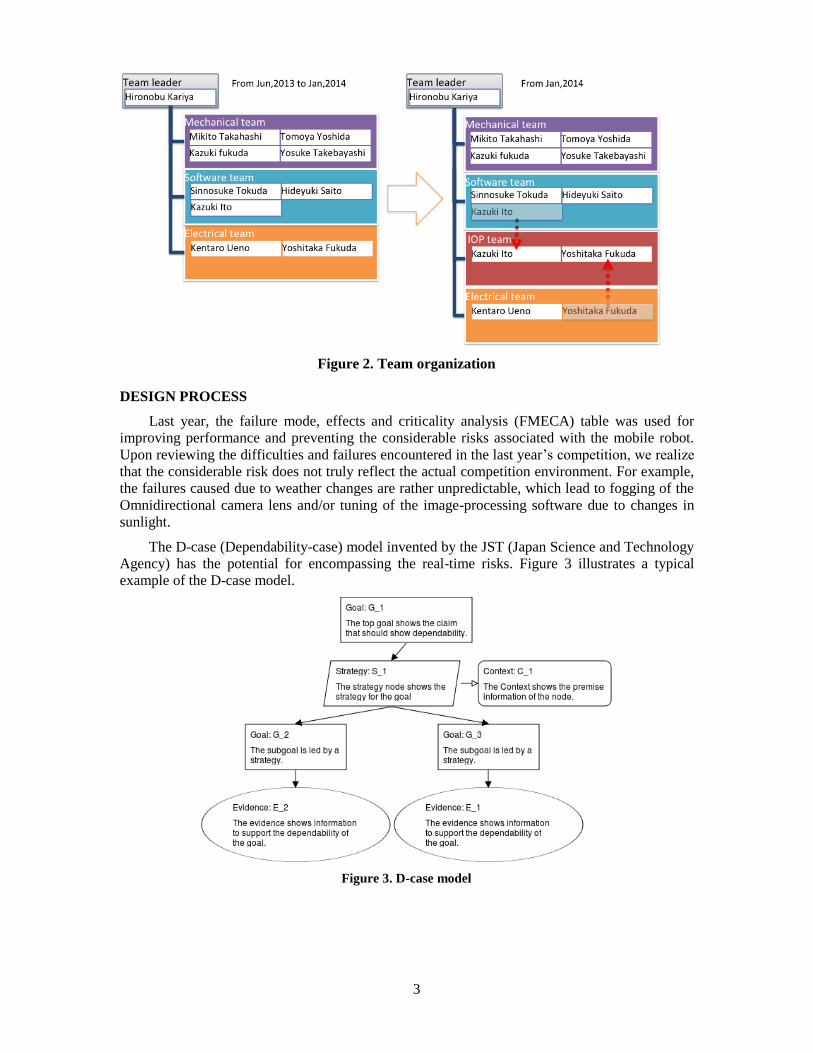
TEAM ORGANIZATION
Figure 2 shows the list of team members from various groups, including mechanical, electrical
and software experts, involved during the early stages of our team organization. Based on the
amendment in the IGVC2014 IOP rules, the software and electrical subgroups have been
reorganized into three sub-groups, as software, electrical, and IOP.
The team leader is responsible for managing and leading the three subgroups toward the
completion of their respective components through frequent team meetings and discussions.
Overall, the time spent for building Orange2014 is approximately 1200 man hours.
3
Figure 2. Team organization
DESIGN PROCESS
Last year, the failure mode, effects and criticality analysis (FMECA) table was used for
improving performance and preventing the considerable risks associated with the mobile robot.
Upon reviewing the difficulties and failures encountered in the last year’s competition, we realize
that the considerable risk does not truly reflect the actual competition environment. For example,
the failures caused due to weather changes are rather unpredictable, which lead to fogging of the
Omnidirectional camera lens and/or tuning of the image-processing software due to changes in
sunlight.
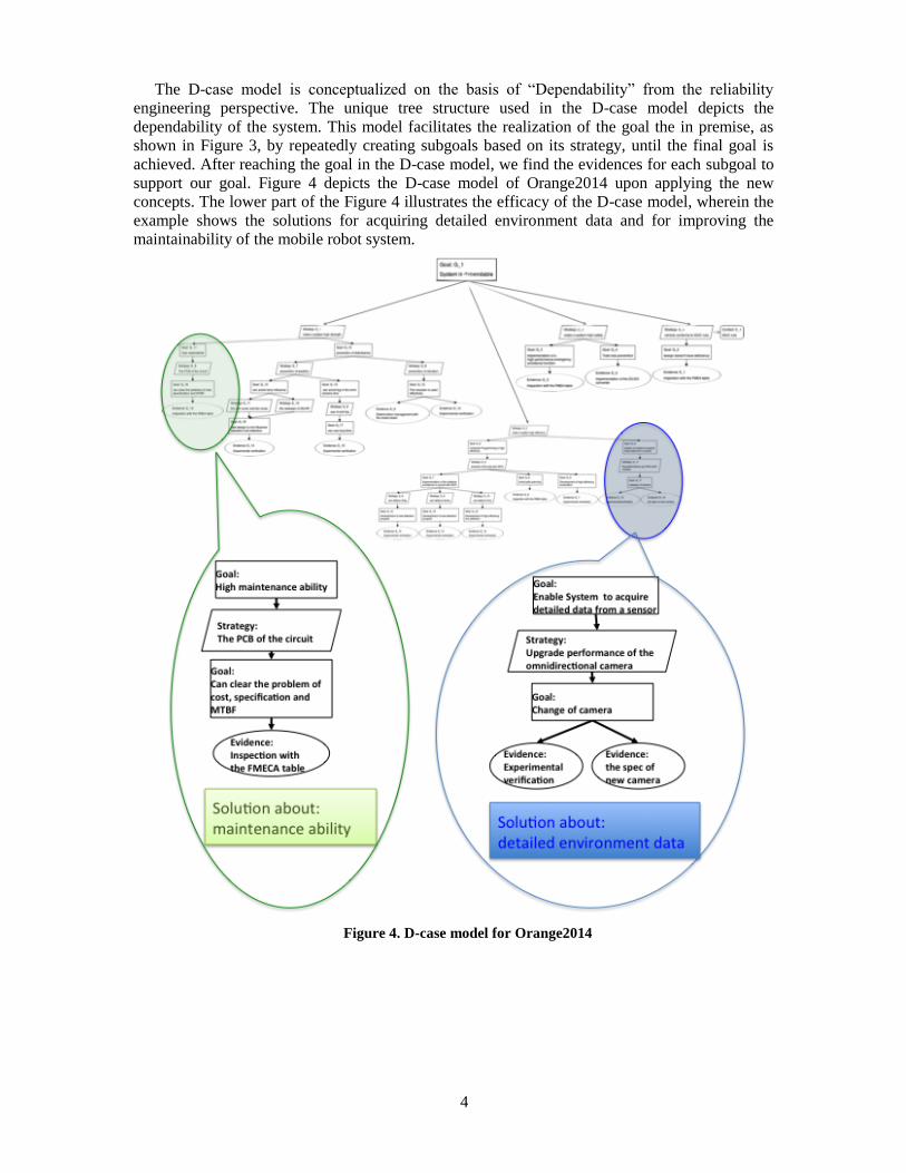
The D-case (Dependability-case) model invented by the JST (Japan Science and Technology
Agency) has the potential for encompassing the real-time risks. Figure 3 illustrates a typical
example of the D-case model.
Figure 3. D-case model
4
The D-case model is conceptualized on the basis of “Dependability” from the reliability
engineering perspective. The unique tree structure used in the D-case model depicts the
dependability of the system. This model facilitates the realization of the goal the in premise, as
shown in Figure 3, by repeatedly creating subgoals based on its strategy, until the final goal is
achieved. After reaching the goal in the D-case model, we find the evidences for each subgoal to
support our goal. Figure 4 depicts the D-case model of Orange2014 upon applying the new
concepts. The lower part of the Figure 4 illustrates the efficacy of the D-case model, wherein the
example shows the solutions for acquiring detailed environment data and for improving the
maintainability of the mobile robot system.
Figure 4. D-case model for Orange2014

5
MECHANICAL DISIGN
Based on the detailed team discussions and results of the D-case model analysis, our mobile
robot concept is defined as the mobile robot portability.
In pursuit of a compact design for the mobile robot in Orange2013, we encountered
difficulties in assembling, especially the electrical circuit box, according to the results of the
D-case model analysis. To improve the feasibility of assembling accessibility in the electrical
circuit box, we redesigned Orange2013 to a newer form in Orange2014. Figure 5 shows the new
CAD design of Orange2014.
Orange2014 consists of an actuator part, detachable circuit box part, and pole part for
attaching the sensors, such as 3D LIDAR. Moreover, to circumvent rain-related issues, we have
designed a raincoat and a fan cover attached to the circuit box.
Figure 5. New design of Orange2014
Chassis and Circuit Box
The chassis used for the Orange2014 is the YAMAHA electric chair (JW-Active) and some
short poles. The circuit box is positioned on the top of the chassis, whereas the bottom of the
chassis offers enough space for payload. The circuit box is made of aluminum and has a width of
41 cm (1.35 feet), depth of 39 cm (1.28 feet), and height of 21 cm (0.69 feet). As a change from
the last year’s design, the circuit box is demountable. This allows the mobile robot to be taken
from the home country, without the need for dismantling the circuit box each time. Besides, the
mobile robot can be easily carried everywhere and the circuit box can be built rather quickly.
Figure 6 shows the CAD design of the chassis and circuit box of Orange2014.

6
Figure 6. CAD design of the circuit box and chassis of Orange2014
3D Light Detection and Ranging
On the basis of the D-case model analysis, Orange2014 has been completely redesigned with
3D LIDAR module to incorporate a rainproof design and to improve smooth rotational
mechanism for reducing unwanted motion. Figure 7 shows the comparison of 3D LIDAR used in
Orange2013 and Orange2014.
Figure 7. Comparison of 3D LIDAR used in Orange2013 and Orange2014
Omnidirectional Camera
As shown in Figure 9(a), most pixels of the straight-line component in omnidirectional image
are diagonally distributed. To improve the resolution par grid for straight-line pixels in the
omnidirectional image, the camera is rotated by 45° with respect to the yaw axis. This enhances
the projected straight-line pixels by approximately more than 140%, as shown in Figure 9(b).

7
Figure 8. The New omnidirectional camera
(a) Conventional camera view (b) 45° rotated camera view
Figure 9. Omnidirectional camera view
8
ELECTRICAL DESIGN
Electrical Design
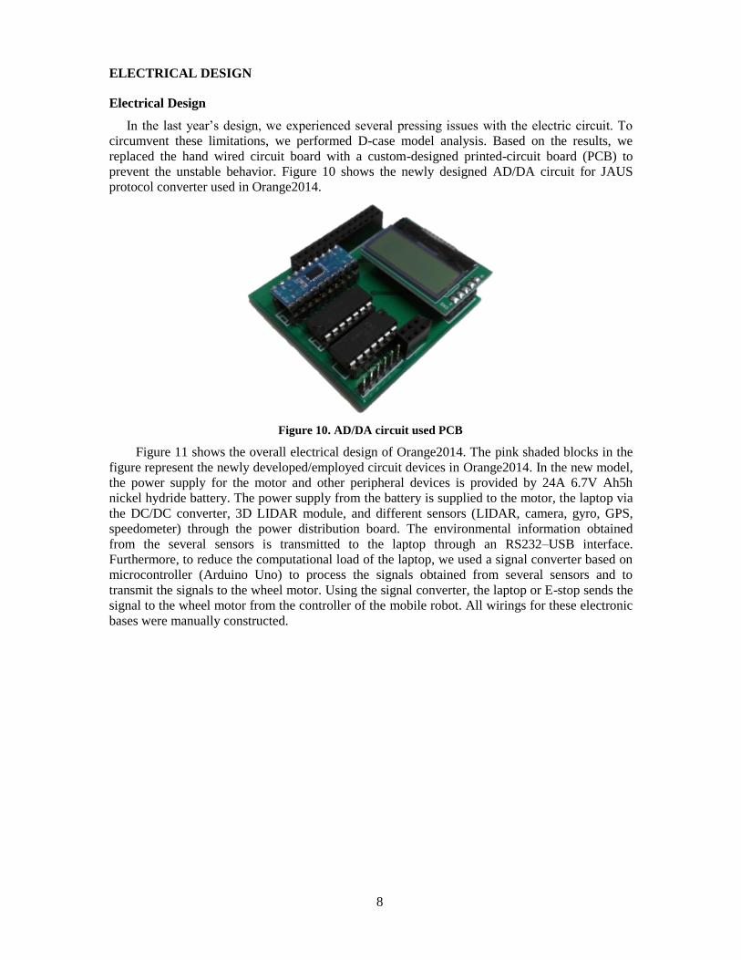
In the last year’s design, we experienced several pressing issues with the electric circuit. To
circumvent these limitations, we performed D-case model analysis. Based on the results, we
replaced the hand wired circuit board with a custom-designed printed-circuit board (PCB) to
prevent the unstable behavior. Figure 10 shows the newly designed AD/DA circuit for JAUS
protocol converter used in Orange2014.
Figure 10. AD/DA circuit used PCB
Figure 11 shows the overall electrical design of Orange2014. The pink shaded blocks in the
figure represent the newly developed/employed circuit devices in Orange2014. In the new model,
the power supply for the motor and other peripheral devices is provided by 24A 6.7V Ah5h
nickel hydride battery. The power supply from the battery is supplied to the motor, the laptop via
the DC/DC converter, 3D LIDAR module, and different sensors (LIDAR, camera, gyro, GPS,
speedometer) through the power distribution board. The environmental information obtained
from the several sensors is transmitted to the laptop through an RS232–USB interface.
Furthermore, to reduce the computational load of the laptop, we used a signal converter based on
microcontroller (Arduino Uno) to process the signals obtained from several sensors and to
transmit the signals to the wheel motor. Using the signal converter, the laptop or E-stop sends the
signal to the wheel motor from the controller of the mobile robot. All wirings for these electronic
bases were manually constructed.

9
Figure 11. Electrical design of Orange2014
Sensors and Processing Unit
The Orange2014 is equipped with six sensors for acquiring the environmental information.
Table 2 summarizes the specifications and targets of each sensor in Orange2014. The main
controller for Orange2014 is the laptop (FUJITU LIFEBOOK A561/C) with an Intel Core i5
processor and memory of 16 GB, running on Windows 7 OS.
Table 2. Sensors unit
Sensor Product name Target Specification
LIDAR
HOKUYO
UTM-30LX
URG-04LX-UG01
・Obstacle detection
・Mapping
Angular range is 240/270
deg. Angular resolution is
0.25/0.352°.
Speedometer Raspberry Pi
Model B ・Self-localization
This module calculates the
speed from the pulse signal of
the rotary encoder.
3D LIDAR HOKUYO
UTM-30LX
・Obstacle detection
・Mapping

10
Omnidirectional
camera
Vstone
VS-C42N-TK
・Obstacle detection
・Line detection
・Mapping
D-GPS Hemisphere A100 ・Self-localization Accuracy is 0.6 m(2 feet),
and the output rate is 20 Hz.
Gyroscope
Japan Aviation
Electronics Industry
JG-35FD ・Self-localization
Angular speed is 200°. and
the response frequency is 20
Hz/s.
IOP CHALLENGE
IOP Interface Tasks
In view of the significant rule changes established in the IOP challenge for this year, we
decided to assign two persons for the IOP team from the software and electrical teams. Table 3
summarizes the additional JAUS query messages that were included to comply with the new IOP
challenge rules. For the sake of simplicity, we have not shown the JAUS query messages that
were implemented last year.
Table 3. New supported query in Orange2014
Capabilities Discovery Platform Management Task
Query Services Discovery
Core Services Task Register Services
Event Query Configuration
Query Event Query Sub-system List
Create Event Query Services
Update Event Liveliness
Cancel Event Query Heartbeat Pulse
Event Navigation and Reporting Task
Access Control Local Waypoint Driver
Release Control Set Travel Speed
Query Authority Set Local Waypoint
Query Timeout Local Waypoint List Driver
Set Authority Query Travel Speed
Management
Reset
Set Emergency
Clear Emergency
Liveliness
Query Heartbeat Pulse
JAUS Protocol Converter
The JAUS protocol converter module used in Orange2013 was developed by an
Arduino-based embedded microcontroller. In Orange2014, we have used a Raspberry Pi
microcontroller system with Linux to enhance the intelligent controlling ability, fast message
response, as well as the multitasking capability of the system. Besides, the use of raspberry pi
enables faster message processing, which is approximately 43 (=700MHz/16MHz) times faster

11
when compared with the Arduino-based embedded microcontroller used in Orange2013. Figure
12 shows the new JAUS protocol converter module used in Orange2014.
Figure 12. New JAUS protocol converter
SOFTWARE INTEGRATION
This section describes the software integration of Orange2014, as illustrated in Figure 13. For
the simplicity of integration, the software systems were developed using MATLAB. Besides, we
also increased the memory from 8 GB to 16 GB and changed from HDD to SSD, to reduce the
time required for data acquisition, and to enhance the system’s ability to handle a large amount of
data. This allows the mobile robot to be programmed much more intelligently than the last year’s
model.
Figure 13. Software integration

12
OBSTACLE RECOGNITION
Line Detection
During IGVC2013, the rapid changes in the weather conditions induced variations in the color
tone of the images generated by the omnidirectional camera. Such tone changes and fixed
threshold of the binarized image often lead to line detection failure. Figure 14 shows the typical
example of line detection failure in IGVC2013 image. The abovementioned shortcoming can be
circumvented by adjusting the line detection brightness level.
Figure 14. Failure of line detection
To adapt the rapid change in color tone, we introduced the new technique of color patch
correcting image processing. Figure 15 shows the actual implementation of color patch in
Orange2014. The comparison of the observed color patch and the environmental color illustrates
that the color of the target object can be clearly identified regardless of the changes in the weather
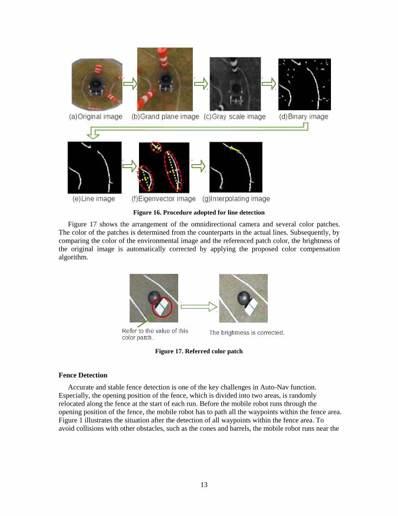
condition. Figure 16 shows the procedure of line detection using the color patch correction image
method for omnidirectional image. Figure 16(a) shows the representative image captured by the
omnidirectional camera, and Figure 16(b) shows the reconstructed ground image. After
reconstruction, the RGB color image is converted to a gray scale image, using only the B
component, as shown in Figure 16(c). We use template matching to binarize the gray scale image.
Figure 16(d) shows the binary image. The isolated noise in the binary image is removed using
Quad tree. The filtered image thus obtained is shown in Figure 16(e). The lines on the image are
piece-wise, which are interpolated by using the eigenvector. After recognizing the lines, the
mobile robot subsequently evaluates the eigenvector of the lines. Figure 16(f) shows the
eigenvector image. Using the eigenvector, the lines are interpolated.
Figure 15. Color patch
13
Figure 16. Procedure adopted for line detection
Figure 17 shows the arrangement of the omnidirectional camera and several color patches.
The color of the patches is determined from the counterparts in the actual lines. Subsequently, by
comparing the color of the environmental image and the referenced patch color, the brightness of
the original image is automatically corrected by applying the proposed color compensation
algorithm.
Figure 17. Referred color patch
Fence Detection
Accurate and stable fence detection is one of the key challenges in Auto-Nav function.
Especially, the opening position of the fence, which is divided into two areas, is randomly
relocated along the fence at the start of each run. Before the mobile robot runs through the
opening position of the fence, the mobile robot has to path all the waypoints within the fence area.
Figure 1 illustrates the situation after the detection of all waypoints within the fence area. To
avoid collisions with other obstacles, such as the cones and barrels, the mobile robot runs near the

14
fence to find the opening position of the fence by using LIDAR. Once the opening position of the
fence is identified, the mobile robot turns and moves through the opening position.
As illustrated in Figure 18, when the LIDAR detects the fence, the mobile robot sets the
virtual waypoint to the forward position for searching. When the LIDAR detects the opening
position, the virtual waypoint is changed, as shown in Figure 19, to move through the opening
position.
Figure 18. Strategy for identifying the opening position of the fence
Figure 19. Method for changing the virtual waypoint to find the opening position of the fence
Flag Detection
To find a safe pathway in the flagged area, we have developed a new flag detection algorithm
by using LIDAR. The LIDAR often fails to detect the flag wire owing to its low resolution when
compared to the flag wire diameter. To overcome this limitation, we have employed a
SLAM-based occupancy grid map detection algorithm. Furthermore, to facilitate safe navigation,
we define a minimum grid size of about 1010 cm (0.320.32 feet) for detecting the flag wire
area. Figure 21 shows the typical example of flag wire detection based on the proposed

15
SLAM-based occupancy grid map. Because of the gird size and accuracy of LIDAR, a maximum
range profile of 2 m (6.6 feet) is used for building the grid map of the flagged area. As shown in
left picture of Figure 20, virtual lanes are generated based on the grid map of the flagged area, to
facilitate safe navigation.
Figure 20. Obstacle grid map
PATH PLANNING
Self-localization and Mapping
As mentioned earlier, the variations in weather conditions greatly influenced the mobile robot
image processing system in IGVC2013. A deeper insight on the last year’s data indicated that the
accuracy of self-localization with GPS was greatly influenced by weather conditions. To improve
the accuracy of self-localization regardless of the weather condition, we used LIDAR and
omnidirectional camera based SLAM algorithm, when the GPS signal becomes unreliable.
Figure 21 shows the self-localized global map generated for the mobile robot. To compensate
the accuracy of the global map, the local maps observed from both the LIDAR and the
omnidirectional camera are combined by applying the template matching technique.
Figure 21. FNCC template matching

16
In Orange2014, we have used FNCC (Fast Normalized Cross Correlation) to achieve real-time
self-localization and global map correction based on the observed local map. Figure 22(a) shows
the global map that is corrected by using the template match technique. Figure 22 (b) shows the
comparison of the self-localization results.
(a) Locus of self-localization (b) Comparison of the self-localization results
Figure 22. Self-localization result
Path Planning
We achieved stabilized path generation by combining A* algorithm in the potential method
for the path planning. This year, we plan to refine this plan. Based on the design process and
IGVC2013, we frequently observed left and right path switching problem which result the
colliding with the obstacle in front of mobile robot. Figure 23 shows the planning scheme after
fixing the errors. To avoid path switching problem, we newly introduce virtual obstacle, the
mobile robot enables the generation of more stable and smooth path planning.
Figure 23. Path planning realized by combining A* and Potential method

17
PERFORMANCE
This section discusses the performance of Orange2014. Its specifications are based on
YAMAHA electric wheelchair (JW-Active). The hardware of the mobile robot has been devised
considering the safety factors of not only the circuits but also ensuring the surrounding safety.
Specifications of the Mobile Robot
Table 4. Performance of the mobile robot
Measurement Performance prediction Performance result
Speed 5.7 km/h (3.5 mph) 5.6 km/h (3.4 mph)
Ramp climbing ability 10° incline 10.2° incline
Reaction time 0.20 s 0.25 s
Battery life 3 h 2 hours 20 minutes
Obstacle detection distance 0–10 m (0-33 feet) 0–10 m (0-33 feet)
Waypoint navigation 0.10 m( 0.33feet) 0.14 m( 0.46 feet)
Safety
Orange2014 is equipped with two different types of emergency stop systems, namely, the
E-stop and wireless E-stop, to prevent any unpredictable accidents. The color of the manual
E-stop button is red, while the E-stop box is colored in black and yellow stripes for easy
identification. The wireless E-stop is designed on the Arduino-based embedded microcontroller
module with XBee transmitter/receiver. According to the specifications of the XBee device, the
maximum wireless communication range is approximately 33 m (108 feet), allowing the mobile
robot to be stopped remotely in case of an emergency.
To identify the requirement of manual or autonomous modes, a helically wrapped LED ribbon
strip is employed as a safety light on the central pole of the mobile robot. The LED ribbon
displays a stable (turned on) or flashing light when the mobile robot is in the autonomous or
manual mode, respectively.
Cost
Table 5. Estimated developmental cost of Orange2014
Components Retail cost Team cost Description
YAMAHA JW-Active $5,600 $0 Electric wheelchair
HOKUYO UTM-30LX $4,000 $0 LIDAR
VS-C42N-TK $2,613 $2,613 Omnidirectional camera
CSSD-S6tT256NHG5Q $175 $175 SSD
I-O DATA GV-USB2 $50 $0 USB video capture cable
Japan Aviation Electronics Industry JG-35FD $5,800 $0 Fiber optic gyroscope
Hemisphere A100 $2,414 $0 DGPS
FUJITSULIFEBOOK A561/C $1,000 $0 Laptop personal computer
Mechanical parts $483 $483 Various mechanical components
Electronic parts $268 $268 Various electrical components
Total $22,403 $3,539

18
CONCLUSION
In this paper, we present the design and implementation of Orange2014 using the D-case
model, which was used to address the hardware and software problems identified in the last
year’s mobile robot (Orange2013).
Moreover, to comply with the new rule changes established in IGVC2014, we developed a
robust and reliable robotic system utilizing a new 3D LIDAR module, omnidirectional camera,
and improved obstacle detection algorithm. These capabilities are expected to improve the safety,
dependability, and durability of the mobile robot. Redesigned with these new functionalities, we
look forward to a favorable placement of Orange2014 in this year’s IGVC.
REFARENCE
1 S. Thrun, W. Burgard, and D. Fox, "Probabilistic Robotics, " The MIT-Press,2005.
2 M. Montemerlo, S. Thrun, D. Koller, and B. Wegbreit, "FastSLAM: A Factored
Solution to the Simultaneous Localization and Mapping Problem,” Proceedings of AAAI
National Conf. on Artificial Intelligence, pp.593-598, 2002.
3 J.Negishi, N.Ohta, and H.Hiyoshi, "Quantitative Color Measurement Using Consumer
Oriented Digital Cameras, " The Institute of Electronics, Information and
Communication Engineers. Vol. J91-D, No.6, pp. 1663-1671, 2008 (In Japanese)