oregon manufactured dwelling installation … · method rulings acceptable statewide, see ors...
TRANSCRIPT

2010
OREGON
MANUFACTURED
DWELLING
INSTALLATION
SPECIALTY CODE
Effective April 1, 2010
DEPARTMENT OF CONSUMER and BUSINESS SERVICES
BUILDING CODES DIVISION


2010 OREGON MANUFACTURED DWELLING
INSTALLATION SPECIALTY CODE
Authorized by ORS 446.185
Oregon Department of Consumer and Business Services
Building Codes Division
P.O. Box 14470
1535 Edgewater Street NW
Salem, Oregon 97309-0404
bcd.oregon.gov
First Printing: January 19, 2010
ORIGIN AND DEVELOPMENT OF THE
2010 OREGON MANUFACTURED DWELLING INSATLLATION SPECIALTY CODE
The Oregon Manufactured Dwelling Installation Specialty Code was originally published under the title
Oregon Manufactured Dwelling Standard (OMDS) in 1996 and again in 1997. In April 2002 the
Oregon Manufactured Dwelling and Park Specialty Code (MD&P) was published. The MD&P was the
result of an extensive rewrite of the code and the inclusion of a chapter devoted to the construction of
manufactured dwelling parks. This is the fourth publication of the original code. This code is typically
adopted and amended every three years.
The 2010 Oregon Manufactured Dwelling Installation Specialty Code was developed with four
purposes in mind. The first and most important is to provide safe, accessible, and energy-efficient
manufactured dwelling installations. The second is to improve the quality of manufactured dwelling
installations and inspections by providing uniform and consistent installation requirements. The third is
to ensure consistency among municipalities in the plan review and inspection of manufactured
dwelling installations. Finally, this code meets or exceeds the minimum requirements in the Model
Manufactured Home Installation Standards established by the Department of Housing and Urban
Development.
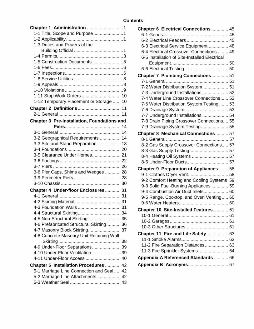
Contents
Chapter 1 Administration ............................ 1
1-1 Title, Scope and Purpose ....................... 1
1-2 Applicability ............................................ 1
1-3 Duties and Powers of the
Building Official ...................................... 1
1-4 Permits................................................... 3
1-5 Construction Documents ........................ 5
1-6 Fees ....................................................... 6
1-7 Inspections ............................................. 6
1-8 Service Utilities ...................................... 8
1-9 Appeals .................................................. 8
1-10 Violations ............................................. 9
1-11 Stop Work Orders .............................. 10
1-12 Temporary Placement or Storage ...... 10
Chapter 2 Definitions ................................. 11
2-1 General ................................................ 11
Chapter 3 Pre-Installation, Foundations and
Piers........................................... 14
3-1 General ................................................ 14
3-2 Geographical Requirements ................. 14
3-3 Site and Stand Preparation .................. 18
3-4 Foundations ......................................... 20
3-5 Clearance Under Homes ...................... 21
3-6 Footings ............................................... 22
3-7 Piers .................................................... 26
3-8 Pier Caps, Shims and Wedges ............ 28
3-9 Perimeter Piers .................................... 28
3-10 Chassis .............................................. 30
Chapter 4 Under-floor Enclosures ............ 31
4-1 General ................................................ 31
4-2 Skirting Material ................................... 31
4-3 Foundation Walls ................................. 31
4-4 Structural Skirting ................................. 34
4-5 Non-Structural Skirting ......................... 35
4-6 Prefabricated Structural Skirting ........... 36
4-7 Masonry Block Skirting ......................... 37
4-8 Concrete Masonry Unit Retaining Wall
Skirting ................................................ 38
4-9 Under-Floor Separations ...................... 39
4-10 Under-Floor Ventilation ...................... 39
4-11 Under-Floor Access ........................... 40
Chapter 5 Installation Procedures ............ 42
5-1 Marriage Line Connection and Seal ..... 42
5-2 Marriage Line Attachments .................. 42
5-3 Weather Seal ....................................... 43
Chapter 6 Electrical Connections ............. 45
6-1 General ................................................ 45
6-2 Electrical Feeders ................................ 45
6-3 Electrical Service Equipment................ 48
6-4 Electrical Crossover Connections ........ 49
6-5 Installation of Site-Installed Electrical
Equipment ............................................ 50
6-6 Electrical Testing .................................. 50
Chapter 7 Plumbing Connections ............. 51
7-1 General ................................................ 51
7-2 Water Distribution System .................... 51
7-3 Underground Installations .................... 52
7-4 Water Line Crossover Connections ...... 52
7-5 Water Distribution System Testing ....... 53
7-6 Drainage System ................................. 53
7-7 Underground Installations .................... 54
7-8 Drain Piping Crossover Connections .... 55
7-9 Drainage System Testing ..................... 55
Chapter 8 Mechanical Connections .......... 57
8-1 General ................................................ 57
8-2 Gas Supply Crossover Connections..... 57
8-3 Gas Supply Testing .............................. 57
8-4 Heating Oil Systems ............................ 57
8-5 Under-Floor Ducts ................................ 57
Chapter 9 Preparation of Appliances ....... 58
9-1 Clothes Dryer Vent ............................... 58
9-2 Comfort Heating and Cooling Systems 59
9-3 Solid Fuel-Burning Appliances ............. 59
9-4 Combustion Air Duct Inlets ................... 60
9-5 Range, Cooktop, and Oven Venting ..... 60
9-6 Water Heaters ...................................... 60
Chapter 10 Site-Installed Features ............ 61
10-1 General .............................................. 61
10-2 Garages ............................................. 61
10-3 Other Structures ................................. 61
Chapter 11 Fire and Life Safety ................. 63
11-1 Smoke Alarms.................................... 63
11-2 Fire Separation Distances .................. 63
11-3 Fire Sprinkler Systems ....................... 64
Appendix A Referenced Standards ........... 66
Appendix B Acronyms ............................... 67

2010 Oregon Manufactured Dwelling Installation Specialty Code
1
CHAPTER 1
ADMINISTRATION
1-1 Title, Scope and Purpose.
1-1.1 Title. These provisions shall be known as the Oregon Manufactured Dwelling Installation Specialty Code, and shall be cited as such and will be referred to herein as “this code.”
1-1.2 Scope. The provisions of this code shall apply to the installation of manufactured dwellings.
1-1.3 Purpose. This code is intended to establish the minimum requirements to safeguard public health, safety and general welfare of the consumer, general public, and the owners and occupants of manufactured dwellings. The requirements of this code may be exceeded by a homeowner, contractor, dealer, distributor, financial institution, or manufacturer, but no building official may require a person to exceed this code except where specifically permitted within this code.
1-2 Applicability.
1-2.1 Application. Where, in any specific case, different sections of this code specify different materials, methods of construction or other requirements, the most restrictive shall govern. Where there is a conflict between a general requirement and a specific requirement, the specific requirement shall be applicable. The manufacturer’s installation instructions shall apply to items not covered by this code.
1-2.2 Application of References. References to chapter or section numbers, or to provisions not specifically identified by number, shall be construed to refer to such chapter, section or provisions of this code.
1-2.3 Referenced Codes and Standards. The codes and standards referenced in this code shall be considered part of the requirements of this code to the prescribed extent of each such reference. Where differences occur between provisions of this code and referenced codes and standards, the provisions of this code shall apply. See Appendix A for a list of reference standards.
1-2.4 Partial Invalidity. In the event that any part or provision of this code is held to be illegal or void, it shall not have the effect of making void or illegal any of the other parts or provisions of this code.
1-2.5 Non-applicability. Except where otherwise stated, this code does not apply to the following:
(1) Installation of manufactured dwellings on land owned and occupied by the federal government;
(2) Installation of manufactured dwellings on tribal lands or on land owned and occupied by a tribal council;
(3) Construction or installation of prefabricated structures, modular buildings, or modular homes regulated under ORS 455.010;
(4) Construction of site-built dwellings, except for cabanas;
(5) Manufactured dwellings used for other than dwelling purposes; and
(6) Recreational vehicles regulated under ORS chapter 446.
1-3 Duties and Powers of the Building Official.
1-3.1 General. The building official is hereby authorized and directed to enforce the provisions of this code. The building official shall have the authority to render interpretations of this code and to adopt policies and procedures in order to clarify the application of its provisions. Such interpretations, policies and procedures shall be in compliance with the intent and purpose of this code. Such policies and procedures shall not have the effect of waiving requirements specifically provided for in this code or statewide interpretations of code.
1-3.2 Applications and Permits. The building official shall receive applications, review construction documents and issue permits for the installation of manufactured dwellings for which such permits have been issued and enforce compliance with the provisions of this code.
1-3.3 Notices and Orders. The building official shall issue all necessary notices or orders to ensure compliance with this code.
1-3.4 Inspections. The building official is authorized to make all of the required inspections, or to accept reports of inspection by approved agencies or individuals. Reports of such inspections shall be in writing and be certified by a responsible officer of such approved agency or by the responsible individual. The building official is authorized to engage such expert opinion as deemed necessary to report upon unusual technical

2010 Oregon Manufactured Dwelling Installation Specialty Code
2
issues that arise, subject to the approval of the appointing authority.
1-3.5 Right of Entry. Where it is necessary to make an inspection to enforce the provisions of this code, or where the building official has reasonable cause to believe that there exists in a manufactured dwelling or upon a premises a condition which is contrary to or in violation of this code which makes the manufactured dwelling or premises unsafe, dangerous or hazardous, the building official is authorized to enter the manufactured dwelling or premises at reasonable times to inspect. If the manufactured dwelling or premises is occupied, identification shall be presented to the occupant and entry requested. If the manufactured dwelling or premises is unoccupied, the building official shall first make a reasonable effort to locate the owner or other persons having charge or control of the manufactured dwelling or premises and request entry. If entry is refused, the building official shall have recourse to the remedies provided by law to secure entry.
1-3.6 Department Records. The building official shall keep official records as dictated by OAR 166-150-0020 where a county has jurisdiction, OAR 166-200-0025 where a city has jurisdiction, and OAR chapter 166, division 300 where the State of Oregon has jurisdiction. Such records shall be retained in the official records for the period indicated in the respective OARs noted above. The building official shall maintain a permanent record of all permits issued in flood hazard areas, including copies of inspection reports and certifications required in Section 1-5.8.
1-3.7 Approved Materials and Equipment. Materials, equipment and devices approved by the building official shall be constructed and installed in accordance with this approval. The use of used materials which meet the requirements of this code for new materials is permitted.
1-3.8 Modifications. Wherever there are practical difficulties involved in carrying out the provisions of this code, the building official shall have the authority to grant modifications for individual cases, upon application of the owner or owner’s representative. The building official shall first find that special individual reasons make the strict letter of this code impractical and the modification is in compliance with the intent and purpose of this code, and that such modification does not lessen health,
accessibility, life and fire safety, or structural requirements. The details of the action granting modifications shall be recorded and entered in the files of the department of building safety.
1-3.9 Alternative Materials, Design and Methods of Construction and Equipment. The provisions of this code are not intended to prevent the installation of any material or to prohibit any design or method of construction not specifically prescribed by this code, provided that any such alternative has been approved. An alternative material, design or method of construction shall be approved where the building official finds that the proposed design is satisfactory and complies with the intent of the provisions of this code, and that the material, method or work offered is, for the purpose intended, at least the equivalent of that prescribed in this code in quality, strength, effectiveness, fire resistance, durability and safety. For the process governing alternate method rulings acceptable statewide, see ORS 455.060.
ORS 455.060 is not part of this code but is
reproduced here for the reader’s convenience:
455.060 Rulings on acceptability of material, design
or method of construction; effect of approval. (1)
Any person who desires to use or furnish any material,
design or method of construction or installation in the
state, or any building official, may request the Director
of the Department of Consumer and Business Services
to issue a ruling with respect to the acceptability of any
material, design or method of construction about which
there is a question under any provision of the state
building code. Requests shall be in writing and, if made
by anyone other than a building official, shall be made
and the ruling issued prior to the use or attempted use of
such questioned material, design or method.
(2) In making rulings, the director shall obtain the
approval of the appropriate advisory board as to
technical and scientific facts and shall consider the
standards and interpretations published by the body that
promulgated any nationally recognized model code
adopted as a specialty code of this state.
(3) A copy of the ruling issued by the director shall
be certified to the person making the request. Additional
copies shall be transmitted to all building officials in the
state. The director shall keep a permanent record of all
such rulings, and shall furnish copies thereof to any
interested person upon payment of such fees as the
director may prescribe.
(4) A building official or inspector shall approve the
use of any material, design or method of construction
approved by the director pursuant to this section if the
requirements of all other local ordinances are satisfied.
1-3.10 Tests. Whenever there is evidence of non-compliance with the provisions of this code,

2010 Oregon Manufactured Dwelling Installation Specialty Code
3
or evidence that a material or method does not conform to the requirements of this code, or in order to substantiate claims for alternative materials or methods; the building official shall have the authority to require tests as evidence of compliance to be made at no expense to the municipality. Test methods shall be as specified in this code or by other recognized test standards. In the absence of recognized and accepted test methods, the building official shall approve the testing procedures. Tests shall be performed by an approved agency. Reports of such tests shall be retained by the building official for the period required for retention of public records.
1-4 Permits.
1-4.1 Permits Required. Any person who intends to commence work which is regulated by this code, or to cause any such work to be done, shall first make application to the building official and obtain the required permit. Multiple permits may be required when the proposed work involves two or more code areas (i.e., structural, electrical, plumbing, or mechanical).
1-4.2 Work Exempt from Permit. Exemption from permit requirements of this code shall not be deemed to grant authorization for any work to be done in any manner in violation of the provi-sions of this code or any other laws or ordinances of the municipality. Permits shall not be required for the following: (1) Nonhabitable one-story detached accessory
structures used as tool and storage sheds, playhouses and similar uses, provided the floor area does not exceed 200 square feet and a height of 10 ft. measured from the finished floor level, to the average height of the roof surface.
(2) Except for barriers around swimming pools, fences not over 6 feet high.
(3) Retaining walls that are not over 4 ft. in height measured from the bottom of the footing to the top of the wall, unless supporting a surcharge.
(4) Concrete sidewalks, slabs, platforms and driveways.
(5) Painting, papering, tiling, carpeting, cabinets, counter tops interior wall, floor or ceiling covering and similar finish work.
(6) Swings and other playground equipment. (7) Patio and porch covers not over 200 square
ft. and supported by an exterior building wall. (8) Window awnings supported by an exterior wall
which do not project more than 54 in. from
the exterior wall and do not require additional support.
(9) Nonbearing partitions, except when such partitions create habitable rooms.
(10) Replacement or repair of siding not required to be fire-resistive.
(11) Retrofitted insulation. (12) Masonry repair. (13) Porches and decks, where the floor or deck
is not more than 30 in. above adjacent grade at any point and where in the case of a covered porch, the covered portion of the porch does not come closer than 3 ft. to property lines.
(14) Gutters and downspouts. (15) Door and window replacements (where no
structural member is changed). (16) Re-roofing, where replacement or repair of
roofing does not exceed 30 percent of the required live load design capacity and the roof is not required to be fire-resistive. Exceptions: (1)Permits for re-roofing are required for
structures in wildfire hazard zones as provided in the Oregon Residential Specialty Code, Section R325; and
(2)Structures falling within the scope of Oregon Residential Specialty Code, Section R317.2.
(17) Plastic glazed storm windows. (18) Framed-covered nonhabitable accessory
buildings not more than 500 square feet in area, one story in height and not closer than 3 ft. to a property line, where the structure is composed of a rigid framework that supports a fabric membrane.
1-4.3 Application for Permit. To obtain a permit, the applicant shall first file an application in writing on a form furnished for that purpose. The application shall:
(1) Identify and describe the work to be covered by the permit for which application is made;
(2) Describe the land on which the proposed work is to be done by legal description, street address or similar description that will readily identify and definitely locate the proposed building or work;
(3) Indicate the use and occupancy for which the proposed work is intended;
(4) Be accompanied by construction documents and other information as required in Section 1-5.1;
(5) State the valuation of the proposed work;

2010 Oregon Manufactured Dwelling Installation Specialty Code
4
(6) Be signed by the applicant, or the applicant’s authorized agent;
(7) Give such other data and information as required by the building official; and
(8) Inform the building official when the manufactured dwelling or any portion of the manufactured dwelling will be installed to the manufacturer’s installation instructions in lieu of this code.
1-4.4 Action on Application. The building official shall examine or cause to be examined applications for permits and amendments thereto within a reasonable time after filing. If the application or the construction documents do not conform to the requirements of pertinent laws, the building official shall reject the application in writing, stating the reasons. If the building official is satisfied that the proposed work conforms to the requirements of this code and laws and ordinances applicable, the building official shall issue a permit as soon as practicable.
1-4.5 Time Limitation of Application. An application for a permit for any proposed work shall be deemed to have been abandoned 180 days after the date of filing, unless such application has been pursued in good faith or a permit has been issued; except that the building official is authorized to grant one or more extensions of time for additional periods not exceeding 90 days each. The extension shall be requested in writing and justifiable cause demonstrated.
1-4.6 Validity of Permit. The issuance or granting of a permit shall not be construed to be a permit for, or an approval of, any violation of any of the provisions of this code or of any other laws or ordinance of the municipality. Permits presuming to give authority to violate or cancel the provisions of this code or other laws or ordinances of the municipality shall not be valid. The issuance of a permit based on construction documents and other data shall not prevent the building official from requiring the correction of errors in the construction documents and other data. The building official is also authorized to prevent occupancy or use of a structure where in violation of this code or of any other laws or ordinances of the municipality.
1-4.7 Expiration. Every permit issued shall become invalid unless the work on the site authorized by such permit is commenced within 180 days after its issuance, or if the work authorized on the site by such permit is suspended or abandoned for a period of 180
days after the time the work is commenced. The building official is authorized to grant, in writing, one or more extensions of time, for periods not more than 180 days each. The extension shall be requested in writing and justifiable cause demonstrated.
1-4.8 Suspension or Revocation. The building official is authorized to suspend or revoke a permit issued under the provisions of this code wherever the permit is issued in error or on the basis of incorrect, inaccurate or incomplete information, or in violation of any ordinance or regulation or any of the provisions of this code.
1-4.9 Placement of Permit. The building permit or copy shall be kept on the site of the work until the completion of the project.
1-4.10 Installation Permits. Installation permits include, but are not limited to:
(1) Excavation, grading and placement of fill.
(2) Stand preparation and drainage systems.
(3) Footings and piers.
(4) Foundation and perimeter retaining walls.
(5) Concrete-encased electrodes.
(6) Installation of the vapor barrier.
(7) Structural marriage line connections.
(8) Weather seals and insulation.
(9) Anchoring devices.
(10) Electrical feeder connections.
(11) Electrical crossover connections.
(12) Ship loose electrical fixture installations.
(13) Water supply and valve installation.
(14) Water crossover connections.
(15) Heat tape installation.
(16) Drain line and crossover connections.
(17) Ship loose drain line installations.
(18) Fuel gas supply connections.
(19) Fuel gas crossover connections.
(20) Ducts, flues, and vents.
(21) Skirting.
(22) Roof gutters and down spouts.
(23) Fire separation walls.
(24) Sidewalks.
(25) Driveways located on single lots.
(26) Temporary steps.
(27) Earthquake-resistant bracing when part of the original manufactured dwelling installation.

2010 Oregon Manufactured Dwelling Installation Specialty Code
5
1-5 Construction Documents.
1-5.1 Submittal Documents. Construction documents, statement of special inspections and other data shall be submitted in one or more sets with each permit application. The construction documents shall be prepared by a registered design professional where required by the statutes of the municipality in which the project is to be constructed. Where special conditions exist, the building official is authorized to require additional construction documents to be prepared by a registered design professional.
Exception: The building official shall accept DAPIA approved construction documents where the application of this code or the Oregon Residential Specialty Code requires a registered design professional.
1-5.2 Information on Construction Documents. Construction documents shall be dimensioned and drawn upon suitable material. Electronic media documents are permitted to be submitted when approved by the building official. Construction documents shall clearly indicate the location, nature and extent of the work proposed and show in detail that it conforms to the provisions of this code and relevant laws, ordinances, rules and regulations, as determined by the building official.
1-5.3 Manufacturer’s Installation Instructions. Manufacturer’s installation instructions, as required by this code, shall be available on the site of work at the time of inspection.
1-5.3.1 Information for Construction in Flood Hazard Areas. Manufactured dwellings located in whole or in part in flood hazard areas as established by the municipality, construction documents shall include:
(1) Delineation of flood hazard areas, floodway boundaries and flood zones and the design flood elevation, as appropriate;
(2) The elevation of the proposed lowest floor, including basement; in areas of shallow flooding (AO zones), the height of the proposed lowest floor, including basement, above the highest adjacent grade;
(3) The elevation of the bottom of the lowest horizontal structural member in coastal high hazard areas (V Zone); and
(4) If design flood elevations are not included on the municipalities Flood Insurance Rate Map (FIRM), the building official and the applicant shall obtain and reasonably utilize any
design flood elevation and floodway data available from other sources.
1-5.4 Site Plan. The construction documents submitted with the application for permit shall be accompanied by a site plan showing the size and location of new construction, existing structures on the site, and distances from lot lines. The building official is authorized to waive or modify the requirement for a site plan when the application for permit is for alteration or repair, or when otherwise warranted.
1-5.5 Examination of Documents. The building official shall examine or cause to be examined the accompanying construction documents and shall determine whether the construction indicated and described is in accordance with the requirements of this code and other pertinent laws or ordinances.
1-5.5.1 Approval of Construction Documents. When the building official issues a permit, the construction documents shall be approved, in writing or by stamp, as "Reviewed for Code Compliance." One set of construction documents shall be retained by the building official. The other set shall be returned to the applicant. The applicant shall be keep a set at the site of work and shall be available to inspection by the building official or authorized representative. Construction documents shall be approved in the timelines authorized in ORS 455.467.
ORS 455.467 is not part of this code but is
reproduced here for the reader’s convenience:
455.467 Timelines for approval or disapproval of
certain specialty code building plans; exceptions;
phased permit systems; failure to adhere to
timelines. (1) Except as provided in subsection (2) of
this section, for specialty code plan reviews of simple
low-rise residential dwellings, the Department of
Consumer and Business Services or a municipality that
administers a building inspection program under ORS
455.148 or 455.150 shall approve or disapprove the
specialty code building plan:
(a) For a jurisdiction with a population that is less
than 300,000, within 10 business days of receiving a
complete application, or shall implement the process
described in ORS 455.465.
(b) For a jurisdiction with a population that is
300,000 or more, within 15 business days of receiving a
complete application, or shall implement the process
described in ORS 455.465.
(2) The 10-day and 15-day requirements in
subsection (1) of this section do not apply if:
(a) The plan requires approval by federal, state or
local agencies outside the jurisdiction of the issuing
agency;

2010 Oregon Manufactured Dwelling Installation Specialty Code
6
(b) The plan is for a complex structure that requires
additional review as determined by the department or
municipality; or
(c) Based on conditions that exist in the affected
municipality, the Director of the Department of
Consumer and Business Services authorizes a different
plan review schedule as described in a building
inspection program submitted under ORS 455.148 or
455.150.
1-5.5.2 Previous Approvals. This code shall not require changes in the construction documents, construction or designated occupancy of a structure for which a lawful permit has been issued or otherwise lawfully authorized, and the construction of which has been pursued in good faith within 180 days after the effective date of this code and has not been abandoned.
1-5.6 Design Professional in Responsible Charge. When it is required that documents be prepared by a registered design professional, the building official shall be authorized to require the owner to designate on the building permit application a registered design professional who shall act as the registered design professional in responsible charge. If the circumstances require, the owner shall designate a substitute registered design professional in responsible charge who shall perform the duties required. The building official shall be notified in writing by the owner if the registered design professional in responsible charge has changed or is unable to continue to perform the duties. The registered design professional in responsible charge shall be responsible for reviewing and coordinating submittal documents prepared by others, including phased and deferred submittal items, for compatibility with the design of the building.
1-5.7 Amended Construction Documents. Any changes made during construction that are not in compliance with the approved construction documents shall be resubmitted for approval as an amended set of construction documents.
1-5.8 Retention of Construction Documents. One set of approved construction documents shall be retained by the building official for a period of not less than that authorized by OAR 166-150-0020 where a county has jurisdiction, OAR 166-200-0025 where a city has jurisdiction, and OAR chapter 166, division 300 where the State of Oregon has jurisdiction. The building official shall maintain a permanent record of all permits issued in flood hazard areas, including copies of inspection reports and certifications.
1-6 Fees.
1-6.1 Payment of Fees. A permit shall not be valid until the fees prescribed by law have been paid. Nor shall an amendment to a permit be released until the additional fee, if any, has been paid.
1-6.2 Schedule of Permit Fees. Permit and plan review fees shall be adopted by the municipality, except as otherwise limited by statute, under authority of ORS 455.020 and 455.210.
1-6.3 Work Commencing Before Permit Issuance. Any person who commences any work installing a manufactured dwelling before obtaining the necessary permits shall be subject to an investigation fee equal to the permit fee in addition to the required permit fees.
1-6.4 Related Fees. The payment of the fee for work done in connection to or concurrently with the work authorized by a building permit shall not relieve the applicant or holder of the permit from the payment of other fees that are prescribed by law.
1-6.5 Refunds. The building official is authorized to establish a refund policy.
1-7 Inspections.
1-7.1 General. Construction or work for which a permit is required shall be subject to inspection by the building official. Construction or work shall remain accessible and exposed for inspection purposes until approved. Approval as a result of an inspection shall not be construed to be an approval of a violation of the provisions of this code or of other laws or ordinances of the municipality. Inspections presuming to give authority to violate or cancel the provisions of this code or of other laws or ordinances of the municipality shall not be valid. It shall be the duty of the permit applicant to cause the work to remain accessible and exposed for inspection purposes unless prior arrangements have been made between the permit holder and the building official for work that is not feasible to leave open for inspection. Neither the building official nor the municipality shall be liable for expense entailed in the removal or replacement of any material required to allow inspection.
OAR 918-020-0090(8)(a) to (f) is not part of this code
but is reproduced here for the reader's convenience:

2010 Oregon Manufactured Dwelling Installation Specialty Code
7
918-020-0090 Program Standards.
(8) Inspection Standards. A building inspection
program shall:
(a) Set reasonable time periods between 7 a.m. and 6
p.m. on days its permit office is open, weekends and
holidays excluded, when it will provide inspection
services or alternative inspection schedules agreed to by
the municipality and permittee;
(b) Unless otherwise specified by statute or specialty
code, establish reasonable time periods when inspection
services will be provided following requests for
inspections;
(c) Establish policies and procedures for inspection
services;
(d) Leave a written copy of the inspection report on
site;
(e) Make available any inspection checklists;
(f) Maintain a list of all persons it employs or
contracts with to provide inspection services including
licenses, registrations and certifications held by persons
performing inspection services and evidence of
compliance with all applicable statutory or professional
continuing education requirements;
1-7.1.1 Set-up Inspection. A set-up inspection shall be performed by the building official on each manufactured dwelling installation. The set-up inspection shall include, but is not limited to those items covered by the installation permit identified in Section 1-4.10. This inspection shall be performed prior to the under-floor area being enclosed by skirting or retaining walls.
1-7.1.2. If the under-floor area is enclosed by skirting prior to the set-up inspection, the building official may require the installation permit holder to make all necessary arrangements to have the under-floor area inspected by a certified inspector.
1-7.1.3. Final Inspection. Final inspection shall be made after all work required by the installation permit is completed. Final inspection includes, but is not limited to, verification of the following:
(1) Skirting installation.
(2) Under-floor access.
(3) Under-floor ventilation.
(4) Temporary step removal.
(5) Permanent step or ramp installation.
(6) Permanent landing, guardrail, and handrail construction.
(7) Site grading and drainage.
(8) Sidewalks and driveways.
(9) Under-floor dryer and range exhaust duct through skirting or perimeter foundation and terminated with approved devices.
(10) Smoke alarm location, installation, and test.
(11) Ground fault circuit interrupter (GFCI) test.
(12) Installer's certification tag(s) are installed.
OAR 918-515-0300 & 918-515-0310 is not part of this
code but is reproduced here for the reader's
convenience:
918-515-0300 Requirements for Installer
Certification Tags
(1) Licensed manufactured dwelling installers and
limited skirting installers installing manufactured
dwellings, cabanas, tie-downs, ERB's, and skirting shall
affix a division-issued certification tag to the
manufactured dwelling, cabana, or skirting upon
completion of the installation, and prior to inspection.
(2) Certification tags may be purchased in bulk by
licensed installers, manufactured dwelling dealers, and
limited skirting installers. An application to purchase
certification tags must be submitted to the division in
duplicate and accompanied by the appropriate tag fee.
(3) Only licensed installers and licensed limited
skirting installers may be assigned certification tags by
the dealer or division. Certification tags may only be
affixed by licensed installers and licensed limited
skirting installers upon completion of the installation.
(4) The person purchasing certification tags from the
division is responsible for their security, use, and
reporting.
(5) The division may sell a maximum two-month
supply of certification tags to a manufactured dwelling
dealer based on monthly installations and certification
tag reports submitted to the division.
(6) The division or a manufactured dwelling dealer
may issue a maximum of 30 certification tags to an
installer at one time and a maximum of 30 certification
tags to a limited skirting installer at one time.
(7) Certification tags assigned to licensed installers
and limited skirting installers can only be transferred by
the division.
(8) If an installer or limited skirting installer license is
suspended, revoked, or expires, all unused certification
tags assigned to that person must be returned to the
division.
(9) If a manufactured dwelling dealer is no longer in
business or changes ownership, all unused certification
tags assigned to the original dealer must be returned to
the division.
918-515-0310 Certification Tag Installation
Certification tags shall be affixed to the manufactured
dwelling, cabana or skirting in a permanent manner and
shall be located:
(1) On a cabana: In a visible location on an exterior
wall;
(2) On a manufactured dwelling: In a visible location
on the exterior wall at the rear end of the manufactured
dwelling and near the insignia or HUD label; and
(3) On skirting: In a visible location near the utility
connections.

2010 Oregon Manufactured Dwelling Installation Specialty Code
8
1-7.2 Other Inspections. The building official is authorized to make or require additional inspections of any construction work to ascertain compliance with the provisions of this code and other laws that are enforced by the building official.
1-7.2.1 Fire-Resistance-Rated Construction Inspection. Where fire-resistance-rated construction is required between dwelling units or due to location on property, the building official shall require an inspection of such construction after all lathing and/or wallboard is in place, but before any plaster is applied, or before wallboard joints and fasteners are taped and finished. See Chapter 11.
1-7.3 Inspection Agencies. The building official is authorized to accept reports of approved inspection agencies, provided such agencies satisfy the qualifications and reliability requirements.
1-7.4 Inspection Requests. It shall be the duty of the permit holder or their authorized agent to notify the building official when work is ready for inspection. It shall be the duty of the permit holder to provide access for inspections of the work.
1-7.5 Approval Required. Work shall not be done beyond the point indicated in each successive inspection without first obtaining the approval of the building official. The building official, upon notification, shall make the requested inspections and shall indicate the portion of the construction that is satisfactory as completed, or notify the permit holder or their agent when the work fails to comply with this code. Any portions that do not comply shall be corrected and shall not be covered or concealed until authorized by the building official.
1-8 Service Utilities.
1-8.1 Connection of Service Utilities. No person shall make connections from a utility, source of energy, fuel or power to any building or system that is regulated by this code for which a permit is required, until approved by the building official.
1-8.2 Temporary Connection. The building official shall have the authority to authorize and approve the temporary connection of the building or system to the utility, source of energy, fuel or power.
1-8.3 Authority to Disconnect Service Utilities. The building official shall have the authority to authorize disconnection of a fuel
supply or appliance that does not conform to this code. The building official shall also have the authority to order the disconnection of a gas utility service, or other energy supply to a building, structure, premises or equipment in case of emergency when necessary to eliminate an immediate hazard to life or property. A notice shall be attached to the energy supply or appliances stating the reason for disconnection. Such notices shall not be removed nor shall the system or appliance be reconnected until authorized by the building official. The owner or occupant of the building, structure or service system shall be notified in writing as soon as practical.
1-9 Appeals.
1-9.1 General. In order to hear and decide appeals of orders, decisions or determinations made by the building official relative to the application and interpretation of this code, the municipality shall establish an appeals procedure.
ORS 455.690 is not part of this code but is
reproduced here for the reader's convenience:
455.690 Appeal to advisory boards. Any person
aggrieved by the final decision of a municipal appeals
board or a subordinate officer of the Department of
Consumer and Business Services as to the application of
any provision of a specialty code may, within 30 days
after the date of the decision, appeal to the appropriate
advisory board. The appellant shall submit a fee of $20,
payable to the department, with the request for appeal.
The final decision of the involved municipality or state
officer shall be subject to review and final determination
by the appropriate advisory board as to technical and
scientific determinations related to the application of the
specialty code involved.
1-9.1.1 Alternate Appeals Process. ORS 455.475 provides an alternative appeals process to that set forth by the municipality.
NOTE: Forms for appeals under ORS 455.690 and ORS 455.475 are available online at www.bcd.oregon.gov.
1-9.2 Limitations on Authority. An application for appeal shall be based on a claim that the true intent of this code or the rules legally adopted have been incorrectly interpreted, the provisions of this code do not fully apply, or an equally good or better form of construction is proposed. An appeals board, when appointed, shall have no authority to waive requirements of this code.

2010 Oregon Manufactured Dwelling Installation Specialty Code
9
ORS 455.475 is not part of this code but is
reproduced here for the reader's convenience:
455.475 Appeal of decision of building official. A
person aggrieved by a decision made by a building
official under authority established pursuant to ORS
455.148, 455.150 or 455.467 may appeal the decision.
The following apply to an appeal under this section:
(1) An appeal under this section shall be made first
to the appropriate specialty code chief inspector of the
Department of Consumer and Business Services. The
decision of the department chief inspector may be
appealed to the appropriate advisory board. The decision
of the advisory board may only be appealed to the
Director of the Department of Consumer and Business
Services if codes in addition to the applicable specialty
code are at issue.
(2) If the appropriate advisory board determines that
a decision by the department chief inspector is a major
code interpretation, then the inspector shall distribute
the decision in writing to all applicable specialty code
public and private inspection authorities in the state. The
decision shall be distributed within 60 days after the
board’s determination, and there shall be no charge for
the distribution of the decision. As used in this
subsection, a “major code interpretation” means a code
interpretation decision that affects or may affect more
than one job site or more than one inspection
jurisdiction.
(3) If an appeal is made under this section, an
inspection authority shall extend the plan review
deadline by the number of days it takes for a final
decision to be issued for the appeal.
1-9.3 Qualifications. An appeals board shall consist of members who are qualified by experience and training to pass on matters pertaining to building construction.
1-10 Violations.
1-10.1 Prohibited Acts. Prohibited acts are as described in ORS 455.450.
ORS 455.450 is not part of this code but is
reproduced here for the reader's convenience:
455.450 Prohibited acts. A person shall not:
(1) Violate or procure, aid or abet in the violation of
any final order concerning the application of a provision
of the state building code in a particular case made by
the Director of the Department of Consumer and
Business Services, an advisory board, a state
administrative officer or any local appeals board,
building official or inspector.
(2) Engage in or procure, aid or abet any other person to
engage in any conduct or activity for which a permit,
certificate, label or other formal authorization is required
by any specialty code or other regulation promulgated
pursuant to this chapter without first having obtained
such permit, certificate, label or other formal
authorization.
1-10.2 Notice of Violation. The building official is authorized to serve a notice of violation or order on the person responsible for the installation of a manufactured dwelling in violation of the provisions of this code, or in violation of a detail statement or an approved plan, or in violation of a permit or certificate issued under the provisions of this code. Such order shall direct the discontinuance of the illegal action or condition and the abatement of the violation.
1-10.3 Prosecution of Violation. If the notice of violation is not complied with in the time period prescribed by the notice, the building official is authorized to request the legal counsel of the municipality to institute the appropriate proceeding at law or in equity to restrain, correct or abate the violation.
1-10.4 Violation Penalties. Any person who violates a provision of this code or fails to comply with any of the requirements, or who erects, constructs, alters or repairs a building or structure in violation of the approved construction documents or directive of the building official, or of a permit or certificate issued under the provisions of this code, shall be subject to penalties as prescribed by law.
1-10.5 Penalties. Penalties for violations are prescribed in ORS 455.895 or as adopted by the municipality. Local authority to levy penalties is limited to violations of code application only.
ORS 455.895 is not part of this code but is
reproduced here for the reader's convenience:
455.895 Civil penalties. (1)(a) The State Plumbing
Board may impose a civil penalty against a person as
provided under ORS 447.992 and 693.992. Amounts
recovered under this paragraph are subject to ORS
693.165.
(b) The Electrical and Elevator Board may impose a
civil penalty against a person as provided under ORS
479.995. Amounts recovered under this paragraph are
subject to ORS 479.850.
(c) The Board of Boiler Rules may impose a civil
penalty against a person as provided under ORS
480.670. Amounts recovered under this paragraph shall
be deposited to the General Fund.
(2) The Director of the Department of Consumer and
Business Services, in consultation with the appropriate
board, if any, may impose a civil penalty against any
person who violates any provision of ORS 446.003 to
446.200, 446.225 to 446.285, 446.395 to 446.420,
446.566 to 446.646, 446.666 to 446.746, 479.510 to
479.945, 479.950 and 480.510 to 480.670 and this
chapter and ORS chapters 447, 460 and 693, or any rule
adopted or order issued for the administration and
enforcement of those provisions. Except as provided in
2010 Oregon Manufactured Dwelling Installation Specialty Code
10
subsections (3) and (8) of this section or ORS 446.995, a
civil penalty imposed under this section must be in an
amount determined by the appropriate board or the
director of not more than $5,000 for each offense or, in
the case of a continuing offense, not more than $1,000
for each day of the offense.
(3) Each violation of ORS 446.003 to 446.200 or
446.225 to 446.285, or any rule or order issued
thereunder, constitutes a separate violation with respect
to each manufactured structure or with respect to each
failure or refusal to allow or perform an act required
thereby, except that the maximum civil penalty may not
exceed $1 million for any related series of violations
occurring within one year from the date of the first
violation.
(4) The maximum penalty established by this section
for a violation may be imposed only upon a finding that
the person has engaged in a pattern of violations. The
Department of Consumer and Business Services, by
rule, shall define what constitutes a pattern of violations.
Except as provided in subsections (1) and (9) of this
section, moneys received from any civil penalty under
this section are appropriated continuously for and shall
be used by the director for enforcement and
administration of provisions and rules described in
subsection (2) of this section.
(5) Civil penalties under this section shall be
imposed as provided in ORS 183.745.
(6) A civil penalty imposed under this section may
be remitted or reduced upon such terms and conditions
as the director or the appropriate board considers proper
and consistent with the public health and safety. In any
judicial review of a civil penalty imposed under this
section, the court may, in its discretion, reduce the
penalty.
(7) Any officer, director, shareholder or agent of a
corporation, or member or agent of a partnership or
association, who personally participates in or is an
accessory to any violation by the partnership,
association or corporation of a provision or rule
described in subsection (2) of this section is subject to
the penalties prescribed in this section.
(8) In addition to the civil penalty set forth in
subsection (1) or (2) of this section, any person who
violates a provision or rule described in subsection (2)
of this section may be required by the director or the
appropriate board to forfeit and pay to the General Fund
of the State Treasury a civil penalty in an amount
determined by the director or board that shall not exceed
five times the amount by which such person profited in
any transaction that violates a provision or rule
described in subsection (2) of this section.
(9) If a civil penalty is imposed for a violation of a
provision of ORS 446.566 to 446.646 and the violation
relates to a filing or failure to file with a county assessor
functioning as agent of the department, the department,
after deducting an amount equal to the department’s
procedural, collection and other related costs and
expenses, shall forward one-half of the remaining civil
penalty amount to the county in which the manufactured
structure is located at the time of the violation.
1-11 Stop Work Orders.
1-11.1 Authority. Whenever the building official finds work regulated by this code being performed in a manner either contrary to the provisions of this code or dangerous or unsafe, the building official is authorized to issue a stop work order.
1-11.2 Issuance. The stop work order shall be in writing and shall be given to the owner of the property involved, to the owner’s agent, or to the person doing the work. Upon issuance of a stop work order, the cited work shall immediately cease. The stop work order shall state the reason for the order, and the conditions under which the cited work will be permitted to resume.
1-11.3 Unlawful Continuance. A person who continues any work after having been served with a stop work order, except for work a person is directed to perform to remove a violation or unsafe condition, shall be subject to penalties as prescribed by law.
1-12 Temporary Placement or Storage.
1-12.1. When a manufactured dwelling is placed temporarily on display or in storage by a manufacturer, dealer, or distributor for a period of over thirty (30) days from the date of manufacture, the manufactured dwelling shall be protected according to the following:
(1) Manufactured dwellings shall be adequately supported under the perimeter of each floor section at 10 ft. on center and under the marriage line at each column support post location. Perimeter supports shall start not more than 5 ft. from the end of the home and shall not be located under any window or door opening.
(2) Electrical connection, if any, shall be as required in Section 6-2.5.
(3) Manufactured dwellings occupied or intended to be occupied or manufactured dwellings on display in manufactured dwelling parks, mobile home parks, or manufactured dwelling subdivisions may not be installed temporarily but shall be installed according to this code.

2010 Oregon Manufactured Dwelling Installation Specialty Code
11
CHAPTER 2
DEFINITIONS
2-1 General.
2-1.1 Scope. Unless otherwise expressly stated, the following words and terms shall, for the purposes of this code, have the meanings indicated in this chapter.
2-1.2 Terms Defined in Statute, Administrative Rule, or Other Codes. Where terms are not defined in this code and are defined in the Oregon Revised Statutes, Oregon Administrative Rules, Oregon Electrical Specialty Code, Oregon Structural Specialty Code, Oregon Fire Code, Oregon Mechanical Specialty Code, Oregon Residential Specialty Code, or Oregon Plumbing Specialty Code, such terms shall have meanings ascribed to them as in those statutes, rules, and codes.
2-1.3 Terms not Defined. Where terms are not defined through the methods authorized by this section, such terms shall have ordinarily accepted meanings such as the context implies. Words of common usage are given their plain, natural, and ordinary meanings. Words that have well-defined legal meanings are given those meanings.
Accessible. Able to approach, access a fixture, connection, appliance, or equipment. Access shall be permitted to require the removal of an access panel, door, or similar obstruction.
Accessory Building or Structure. A building or structure that is an addition to or supplements the facilities provided by a manufactured dwelling. Accessory building specifically includes, but is not limited to cabanas, ramadas, storage sheds and garages. Accessory structure specifically includes, but is not limited, to awnings, carports, decks, steps and ramps.
Alteration. Any change, addition, repair, conversion, replacement, modification or removal of any equipment or installation which may affect the operation, construction or occupancy of a manufactured structure.
Anchoring System. Equipment or materials used to secure a manufactured dwelling to the ground.
Approved. Approved or certified by the Department of Consumer and Business Services or its designee.
Awning. Any stationary structure, permanent or demountable, used in conjunction with a manufactured structure, other than window awning, for the purpose of providing shelter from the sun and rain, and having a roof with supports and not more than one wall or storage cabinet substituting for a wall.
Bonding. Permanent joining of metallic parts to form an electrically conductive path that will ensure electrical continuity and the capacity to conduct safely any current likely to be imposed.
Building. Any permanent building but does not include manufactured dwellings or manufactured dwelling accessory buildings.
Cabana. A stationary, light-weight structure which may be prefabricated or demountable, with two or more walls, used adjacent to and in conjunction with a manufactured structure to provide additional living space.
Carport. A stationary structure consisting of a roof with its supports and not more than one wall, or storage cabinet substituting for a wall, and used for sheltering a motor vehicle.
Chassis. The entire transportation system comprising the following subsystems: drawbar and coupling mechanism, frame, running gear assembly, and lights.
DAPIA (Design Approval Primary Inspection Agency). A state or private organization that has been accepted by the Secretary of HUD to evaluate and approve manufactured dwelling designs and quality control procedures.
Drain. A pipe that carries waste, water, or water-borne waste in a drainage system.
Drain, Main. The lowest pipe of a drainage system that receives sewage from all the fixtures within a manufactured dwelling and conducts these wastes to the drain outlet.
Drainage System. All piping, within or attached to the structure, that conveys sewage or other liquid waste to the drain outlet, not including the drain connector.
Earthquake-Resistant Bracing System. A certified and approved anchoring, bracing, or support system designed and constructed to protect the health and safety of the occupants of, and reducing damage to, a manufactured dwelling in the event of an earthquake.

2010 Oregon Manufactured Dwelling Installation Specialty Code
12
Elevation.
Base Flood Elevation (BFE). The elevation of the base flood, including wave height, relative to the datum specified on a municipalities flood hazard map.
Design Flood Elevation (DFE). The elevation of the design flood, including wave height, relative to the datum specified on a municipalities flood hazard map.
Equipment. Materials, appliances, devices, fixtures, fittings, or accessories used in the construction of manufactured dwellings and the fire safety, plumbing, heat-producing, and electrical systems of a manufactured dwelling.
Fill. A man made deposit of materials intended to raise an existing grade.
Flood.
Base Flood. The flood having a one percent chance of being equaled or exceeded in any given year.
Design Flood. The greater of either (1) the base flood or (2) the flood so designated by the municipality as its regulatory flood, with a one percent chance, or less, of being equaled or exceeded in any given year.
Flood Damage-Resistant Material. Any construction material capable of direct and prolonged contact with floodwaters without sustaining any damage that requires more than cosmetic repairs.
Flood Hazard Area. The greater of the either (1) the area within a flood plain subject to a one percent or greater chance of flooding in any year or (2) the area designated as a flood hazard area on a municipalities flood hazard map, or otherwise legally designated.
Flood Insurance Rate Map (FIRM). An official map of a municipality on which FEMA has delineated both the special hazard areas and the risk premium zones applicable to the municipality.
Footing. That portion of the support system that transmits loads directly to the soil.
Foundation Wall. A wall below the floor nearest grade that serves as a structural support for the home.
Frame. The fabricated, rigid substructure that provides support to the affixed manufactured dwelling structure, both during transport and on-site; and provides a platform for
securement of the running gear assembly and the draw bar and coupling mechanism.
Freezing Climate. For the purposes of this code, the Building Codes Division has established that a freezing climate is a climate region where the maximum number of heating degree days exceeds 9,000 hours. Heating degree day hours have been established by the U.S. Department of Energy and further determined by the Oregon Department of Energy.
Garage. A structure located on a manufactured dwelling site designed for the storage of motor vehicles.
Grade. Has the following meanings:
(1) As it relates to plumbing, is the fall (slope) of a pipe in reference to a horizontal plane expressed in inches per foot length; or
(2) As it relates to the earth, is the finished ground level adjoining the building at all exterior walls.
Ground Anchor. Any device at a manufactured dwelling stand designed to transfer manufactured dwelling anchoring loads to the ground.
Installation. Has the following meanings:
(1) As it relates to construction is the arrangements and methods of construction, fire and life safety, electrical, plumbing and mechanical equipment and systems within a manufactured structure; or
(2) As it relates to siting is the manufactured structure and cabana foundation support and tie-down, the structural, fire and life safety, electrical, plumbing and mechanical equipment and material connections and the installation of skirting and temporary steps.
Labeled. Equipment or materials to which has been attached a label, symbol, or other identifying mark of an organization that is acceptable to the building official and concerned with product evaluation, that maintains periodic inspection of production of labeled equipment or materials, and by whose labeling the manufacturer indicates compliance with appropriate standards or performance in a specified manner.
Lot. Any space, area or tract of land, or portion of a manufactured dwelling park or mobile home park, which is designated or used for occupancy by one manufactured dwelling.

2010 Oregon Manufactured Dwelling Installation Specialty Code
13
Lowest Floor. The floor of the lowest enclosed area of a manufactured dwelling. For the purpose of this code, lowest floor shall mean the bottom of the longitudinal chassis frame beam in A zones, and the bottom of the lowest horizontal structural member supporting the home in V zones. An unfinished or flood-resistant enclosure, used solely for vehicle parking, home access or limited storage, shall not be considered the lowest floor, provided the enclosed area is not constructed so as to render the home in violation of the flood-related provisions of this code.
Main Frame. The structural component on which the body of the manufactured dwelling is mounted.
Manufactured Dwelling. A manufactured dwelling, mobile home or residential trailer, as defined in ORS 446.003 (Manufactured dwelling does not mean any building or structure subject to the Oregon Structural Specialty Code, the Oregon Residential Specialty Code, or any unit identified by the manufacturer as a prefabricated structure, modular building, or recreational vehicle).
Manufacturer’s Installation Instructions. As required by 24 CFR 3285.2, manufacturers must provide installation designs and instructions with each new manufactured dwelling that have been approved by the Secretary of Housing and Urban Development or by a DAPIA. These installation instructions are required to equal or exceed the protection provided by 24 CFR 3285 (MMHIS).
Pier. An isolated support used in a support system extending between the footing and the manufactured dwelling.
Porch. An outside walking area having a floor that is elevated more than 8 in. above grade.
Prefabricated Pier. A listed or approved individual pier which is manufactured at an off site location but does not include concrete masonry units or earthquake-resistant bracing systems.
Ramada. Any freestanding roof or shade structure installed or erected above a manufactured dwelling or any portion thereof.
Registered Design Professional. An individual who is registered or licensed to practice their respective design profession as defined by
the statutory requirements of the professional registration laws of the state or municipality in which the project is to be constructed.
Repair. The reconstruction or renewal of any part of an existing manufactured dwelling or piece of equipment for the purpose of its maintenance.
Service Equipment. The equipment containing the disconnecting means, overcurrent protective devices, receptacles, or other means for connecting a manufactured dwelling feeder assembly.
Skirting. A weather resistant material used to enclose the space below the manufactured structure.
Stand. The area of the manufactured dwelling site which has been reserved for the placement of a manufactured dwelling or accessory structure.
Structure. That which is built or constructed.
Support System. A combination of footings, piers, caps, and shims that will, when properly installed, support the manufactured dwelling.
Tie-down. See Anchoring System.
Diagonal Tie. A tie intended to resist horizontal or shear forces and to resist vertical uplift, and overturning forces.
Vertical Tie. A tie intended to resist uplifting and overturning forces.
Under-Floor Enclosure. The perimeter skirting, foundation wall or retaining wall used to enclose the under-floor area of a manufactured dwelling.
Utility Connection. The connection of the manufactured dwelling to existing utilities that include, but are not limited to, electricity, water, sewer, gas, or fuel oil.
2010 Oregon Manufactured Dwelling Installation Specialty Code
14
CHAPTER 3
PRE-INSTALLATION – FOUNDATIONS - PIERS
3-1 General.
3-1.1 Scope. All manufactured dwellings shall be installed to the requirements of this code. Where authorized or required by this code, installation may be according to the manufacturer’s installation instructions, according to site specific engineering, or as allowed by the building official. At the time the permit is issued, the applicant should inform the building official when the manufactured dwelling or any portion of the manufactured dwelling will be installed to the manufacturer’s installation instructions.
3-1.2 Content. This code prescribes the minimum requirements for the siting, design, materials, access, and installation of manufactured dwellings, accessory structures, accessory buildings, earthquake-resistant bracing, and wind and flood resistant anchoring.
3-1.3 Unique Installations. Manufactured dwellings with unique installation requirements specifically addressed by the manufacturer but not addressed in this code shall be installed to the manufacturer’s installation instructions.
3-1.4 Unusual Installations. This code is not intended to limit the appropriate use of materials, equipment, or methods of design or construction not specifically prescribed by this code. A person may design for unusual installations as long as the alternate method or material is at least equivalent to the requirements of this code in suitability, quality, strength, effectiveness, fire resistance, durability, dimensional stability, safety, and sanitation. All alternate methods or materials shall have prior approval from the building official.
3-1.5 Design Loads. Except as otherwise stated, the manufactured dwelling siting, foundation and installation requirements contained in this code shall be based on the following criteria:
(1) Minimum soil bearing capacity of 1,000 PSF.
(2) Minimum pier capacity of 4,000 lbs.
(3) Floor live load (LL) of 40 PSF.
(4) Floor dead load (DL) of 15 PSF.
(5) Wall dead load (DL) of 10 PSF.
(6) Roof live load (LL) of 30 PSF.
(7) Roof dead load (LL) of 10 PSF.
(8) Total manufactured dwelling LL and DL, 105 PSF.
(9) Horizontal wind load of 15 PSF.
(10) Roof uplift of 9 PSF.
3-1.6 Basic Requirement. The foundation shall assure the manufactured dwelling has adequate support, a level floor, flush roof, flush floor, and flush wall connections at the marriage lines of multi-section manufactured dwellings.
3-2 Geographical Requirements.
3-2.1 Frost Line. Footings shall be designed using methods and practices that prevent the effects of frost heave.
3-2.1.1 Conventional Footings. In freezing climates, conventional footings shall be placed below the frost line, unless an insulated foundation or monolithic slab is used. The frost line is as per Table 3-2.1 and where not specific, to the Oregon Residential Specialty Code, Table R301.2(1).
3-2.1.2. Insulated Foundation and Monolithic Slabs. In freezing climates, an insulated foundation or monolithic slab is permitted above the frost line when all relevant site-specific conditions, including soil characteristics, site preparation, ventilation, and insulative properties of the under-floor enclosure are considered. An insulated foundation or monolithic slab system shall be designed by a registered design professional or in accordance with SEI/ASCE 32-01 to prevent the effects of frost heave.
3-2.1.3 Foundation and Retaining Walls. Foundation wall and retaining wall footings shall be placed below the frost line as per Table 3-2.1 and where not specific, to the Oregon Residential Specialty Code, Table R301.2(1).
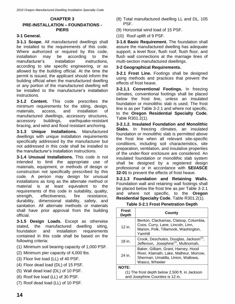
Table 3-2.1 Frost Penetration Depth
Frost Depth
County
12 in.
Benton, Clackamas, Clatsop, Columbia, Coos, Curry, Lane, Lincoln, Linn, Marion, Polk, Tillamook, Washington, Yamhill
18 in. Crook, Deschutes, Douglas, Jackson
(1),
Jefferson, Josephine(1)
, Multnomah,
24 in.
Baker, Gilliam, Grant, Harney, Hood River, Klamath, Lake, Malheur, Morrow, Sherman, Umatilla, Union, Wallowa, Wasco, Wheeler
NOTE:
(1) The frost depth below 2,500 ft. in Jackson and Josephine Counties is 12 in.

2010 Oregon Manufactured Dwelling Installation Specialty Code
15
3-2.2 Special Snow Load Conditions. Manufactured dwellings designed for and located in areas with roof live loads greater than 30 PSF shall be installed to the manufacturer’s installation instructions or designed by a registered design professional.
3-2.3 Wind Resistant Anchoring. To resist overturning, sliding and lateral movement, manufactured dwellings shall be anchored to resist the design wind loads in Section 3-1.5 according to the requirements in Section 3-2.6.
3-2.4 Flood Hazard Areas. When manufactured dwellings are installed in flood hazard areas they shall be elevated and anchored according to the Oregon Residential Specialty Code, Section R324.1.8.
3-2.5 Seismic Design Categories. To identify the different levels of earthquake activity, three seismic design categories have been established in Oregon. See Figure 3-2.5(a).
Figure 3-2.5(a) Seismic Design Category Map
3-2.5.1 Seismic Design Category C. Manufactured dwellings in seismic design category C shall comply with the following. See Figure 3-2.5(b).
(1) Manufactured dwellings shall be limited in height to 3 ft. as measured from the top of the footing to the bottom of the main frame for 75 percent of the under-floor area.
(2) Manufactured dwellings shall be limited in height to 5 ft. – 7 in. as measured from the top of the footing to the bottom of the main frame for 25 percent of the under-floor area.
(3) The fuel gas supply to the manufactured dwelling shall be made with a minimum 6 ft. flexible gas connector.
(4) The maximum height limitations identified in this section may be exceeded when the support system is designed for the appropriate seismic design category by a registered design professional, or the manufacturer’s DAPIA approved plans, and accepted by the building official.
3-2.5.2 Seismic Design Category D1. Manufactured dwellings in seismic design category D1 shall comply with the following. See Figure 3-2.5(b).
(1) Manufactured dwellings shall be limited in height to 3 ft. as measured from the top of the footing to the bottom of the main frame for 75 percent of the under-floor area.
(2) Manufactured dwellings shall be limited in height to 5 ft. – 7 in. (67 in.) as measured from the top of the footing to the bottom of the main frame for 25 percent of the under-floor area.
(3) The fuel gas supply to the manufactured dwelling shall be made with a 6 ft. flexible gas connector.
(4) If the home exceeds 3 ft. from the top of the footing to the bottom of the I-beam, the manufactured dwelling shall be braced or anchored to resist overturning, sliding, and lateral forces according to Section 3-2.5.4.

2010 Oregon Manufactured Dwelling Installation Specialty Code
16
(5) The maximum height limitations identified in this section may be exceeded when the support system is designed for the appropriate seismic design category by a registered design professional, or the manufacturer’s DAPIA approved plans, and accepted by the building official.
3-2.5.3 Seismic Design Category D2. Manufactured dwellings in seismic design category D2 shall comply with the following. See Figure 3-2.5(c).
(1) Manufactured dwellings shall be limited in height to 2 ft. as measured from the top of the footing to the bottom of the main frame for 75 percent of the under-floor area.
(2) Manufactured dwellings shall be limited in height to 5 ft. as measured from the top of
the footing to the bottom of the main frame for 25 percent of the under-floor area.
(3) The fuel gas supply to the manufactured dwelling shall be made with a 6 ft. flexible gas connector.
(4) If the home exceeds 2 ft. from the top of the footing to the bottom of the I-beam, the manufactured dwelling shall be braced or anchored to resist overturning, sliding, and lateral forces according to Section 3-2.5.4.
(5) The maximum height limitations identified in this section may be exceeded when the support system is designed for the appropriate seismic design category by a registered design professional, or manufacturer’s DAPIA approved plans, and accepted by the building official.
Figure 3-2.5(b) Maximum Pier Height for Seismic Zone C & D1
Figure 3-2.5(c) Maximum Pier Height for Seismic Zone D2

2010 Oregon Manufactured Dwelling Installation Specialty Code
17
3-2.5.4 Earthquake-Resistant Bracing. When required, manufactured dwellings shall be anchored or braced to resist seismic forces by any of the following:
(1) Installing an approved earthquake-resistant bracing system.
(2) Installing an approved anchoring system designed to resist seismic conditions.
(3) Installing positive connection piers at the main frame and anchoring with approved ground anchors.
(4) Supporting and securing to a foundation wall, basement wall, or positive connection piers.
(5) Supporting and securing to an approved structural skirting system designed to resist seismic conditions.
(6) Supporting and securing to a foundation system capable of resisting seismic forces designed by a registered design professional and approved by the building official.
3-2.6 Anchoring. Anchoring of a manufactured dwelling shall be according to the following.
(1) The initial installation of all new manufactured dwellings shall be according to one of the following methods:
(a) Installation of approved ground anchors that comply with all the requirements for Wind Zone I in 24 CFR 3285.402 contained within the manufacturer’s installation instructions.
(b) Structural attachment to a foundation system, structural skirting, basement wall, or footing when designed by a registered design professional and approved by the building official. See Section 3-2.6(2)(b) and Figure 3-2.6 for examples of a typical approved anchoring systems.
(c) An earthquake-resistant bracing system shall be installed at a maximum of 24 ft. on center and have a capacity of at least 5,000 lbs. in the lateral and longitudinal directions and 35,000 lbs. vertically, and are limited for use with multisection manufactured dwellings only having a roof slope of 20 degrees or less and supported on piers not greater than 24 in. in height.
(2) The secondary installation of a manufactured dwelling shall be according to one of the following methods, see Figure 3-2.6:
(a) Ground anchors shall be sized and spaced according to the equipment manufacturer’s instructions. The mechanical connections of
the anchoring equipment shall be made according to the equipment manufacturer’s instructions.
(b) Foundation footing U-Bar anchoring ties shall be sized and the U-Bars spaced according to the manufacturer’s instructions. The mechanical connections of the anchoring ties shall be made according to the equipment manufacturer’s instructions.
(A) In the absence of manufacturer’s instructions, the U-Bar attachments shall be installed 11 ft. on center and no more than 12 in. from each end on both sides of the manufactured dwelling.
(B) Tie materials and strapping shall be capable of resisting an allowable working load of 3,150 lbs. with no more than two percent elongation, and shall withstand a 50 percent overload. Tie-downs and ground anchors shall have protection against weather deterioration and corrosion at least equivalent to that provided by a coating of zinc on steel of .30 oz./ft2 of surface coat.
(c) Connector Plate anchoring:
(A) At least 3-1/2 in. x 7 in., 20 gage connector plates no more than 12 in. from each end on both sides and 4 ft. on center for single wide dwellings, and 5 ft. on center for multiple section dwellings.
(B) Plates shall be fastened with a combined total of 32 8d nails into the rim joist and foundation wall top plate.
(d) Plywood trim board anchoring:
(A) Exterior type 15/32 in. grade B plywood at least 3-1/2 in. wide and continuous on both sides of the dwelling.
(B) Trim board shall be secured to the rim joist and the foundation wall top plate with 8d nails 6 in. on center in each row and caulked for weather seal.

2010 Oregon Manufactured Dwelling Installation Specialty Code
18
Figure 3-2.6 Typical Foundation Anchoring
3-3 Site and Stand Preparation.
3-3.1 Suitability of Site. Each site shall be suitable for its intended use and acceptable to the building official based on this code and local land use regulations. Manufactured dwellings shall not be located on land that is unsuitable due to swampy terrain, lack of drainage, or proximity to the breeding places of rodents or vermin unless improvements have been made to the land to eliminate or control the hazards. In areas having highly expansive, compressible, or shifting soils, the building official may require a soil test.
3-3.2 Unforeseen Factors. When unforeseen factors are encountered (i.e., rock formation, high ground water levels, springs, or biological generated gasses), corrective drainage work, acceptable to the building official, shall be completed prior to the siting of the manufactured dwelling.
3-3.3 Grading and Drainage. Site grading and drainage shall be provided according to the following and Figure 3-3.3:
(1) Lots and stands shall be provided with adequate drainage and shall be properly graded to divert surface water away from manufactured dwellings, accessory buildings, and accessory structures.
(2) Roof run-off from manufactured dwellings shall be adequately diverted away from the stand.
(3) Lots shall have sufficient drainage to prevent standing water, excessive soil saturation, or erosion from becoming detrimental to the lot, stand, or any structures.
(4) All drainage shall be diverted away from the home and shall slope a minimum of 1/2 in. per foot away from the foundation for the first 10 ft. Where property lines, wall, slopes, or other physical conditions prohibit this slope, the site shall be provided with drains or swales or otherwise graded to drain water away from the structure. Alternate grading methods may be used if approved by the building official.
(5) Sidewalks, walkways, patio slabs, or driveways abutting the manufactured dwelling stand or foundation shall have a slope of 1/4 in. per 12 in. to divert water away from the stand or foundation. The concrete shall be no closer than 3 in. vertically to any untreated wood or siding.
(6) The slope of cut or fill surfaces shall be no steeper than is safe for the intended use according to Oregon Residential Specialty Code, Section R403.1.9.
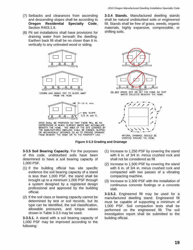
2010 Oregon Manufactured Dwelling Installation Specialty Code
19
(7) Setbacks and clearances from ascending and descending slopes shall be according to Oregon Residential Specialty Code, Section R403.1.9.
(8) Pit set installations shall have provisions for draining water from beneath the dwelling. Earthen back fill shall be no closer than 6 in. vertically to any untreated wood or siding.
3-3.4 Stands. Manufactured dwelling stands shall be natural undisturbed soils or engineered fill. Stands shall be free of grass, weeds, organic materials, highly expansive, compressible, or shifting soils.
Figure 3-3.3 Grading and Drainage
3-3.5 Soil Bearing Capacity. For the purposes of this code, undisturbed soils have been determined to have a soil bearing capacity of 1,000 PSF.
(1) If the building official has site specific evidence the soil bearing capacity of a stand is less than 1,000 PSF, the stand shall be brought up to a minimum 1,000 PSF through a system designed by a registered design professional and approved by the building official.
(2) If the soil class or bearing capacity cannot be determined by test or soil records, but its type can be identified, the soil classification, allowable pressures, and torque values shown in Table 3-3.5 may be used.
3-3.5.1. A stand with a soil bearing capacity of 1,000 PSF may be improved according to the following:
(1) Increase to 1,250 PSF by covering the stand with 6 in. of 3/4 in. minus crushed rock and shall not be considered as fill.
(2) Increase to 1,500 PSF by covering the stand with 6 in. of 3/4 in. minus crushed rock and compacted with two passes of a vibrating compacting machine.
(3) Increase to 2,300 PSF with the installation of continuous concrete footings or a concrete slab.
3-3.5.2. Engineered fill may be used for a manufactured dwelling stand. Engineered fill must be capable of supporting a minimum of 1,000 PSF. Soil compaction tests shall be performed on the engineered fill. The soil investigation report shall be submitted to the building official.

2010 Oregon Manufactured Dwelling Installation Specialty Code
20
Table 3-3.5 Soil Classification
Soil Classification
Soil Description Allowable Soil
Bearing Pressure (PSF)
1
Blow count ASTM D 1586-99
Torque Probe3
Value4
(inch-pounds)- Classification
Number ASTM D 2487-00
or D 2488-00
1 ---- Rock or hard pan 4,000+ ---- ----
2 GW, GP, SW, SP,
GM, SM.
Sandy gravel and gravel; very than dense and/or cemented sands; course gravel/cobbles;
preloaded silts, clays and coral.
2,000 40+ More than 550
3 GC, SC, ML, CL
Sand; silty sand; clayey sand; silty gravel; medium dense
course sands; sandy gravel; and very stiff silt, sand clays.
1,500 24 – 39 351 – 550
4A CG, MH2
Loose to medium dense sands; firm to stiff clays and silts;
alluvial fills. 1,000 18 – 23 276 – 350
4B CH, MH2
Loose sands; firm clays; alluvial fills
1,000 12 – 17 175 – 275
5 OL, OH, PT Uncompacted fill, peat; organic
clays Refer to Note (5) 0 – 11 Less than 175
NOTES:
(1) The values provided in this table have not been adjusted for overburden pressure, embedment depth, water table height, or settlement problems.
(2) For soils classified as CH or MH, without either torque probe values or below count test results, selected anchors must be rated for a 4B soil.
(3) The torque test probe is a device for measuring the torque value of soils to assist in evaluating the holding capacity of the soil in which the ground anchor is placed. The shaft must be of suitable length for the full depth of the ground anchor.
(4) The torque value is a measure of the load resistance provided by the soil when subject to the turning or twisting force of the probe.
(5) In lieu of determining the soil bearing capacity by use of the methods shown in the table, an allowable pressure of 1,500 PSF may be used, unless the site-specific information requires the use of lower values based on soil classification and type.
3-3.6 Moisture Barrier. Every manufactured dwelling stand shall have a moisture barrier installed. The moisture barrier shall be a minimum 6 mil polyethylene membrane sheeting installed according to the following:
(1) The entire area under the heated portion of the manufactured dwelling shall be covered with sheeting, it shall be overlapped by at least 12 in. at all joints;
(2) All holes, tears, and penetrations in the sheeting shall be adequately sealed or patched;
(3) Sheeting shall be installed above the stand and any poured-in-place concrete footing. If sheeting is installed below the poured-in-place concrete slab, an additional layer shall be installed on top of the footing. If the concrete slab will be constructed with a
foundation encased electrode, there shall not be a vapor barrier under the concrete; and
(4) Sheeting is not permitted on the ground below factory-built porches, decks, or landings having open floors constructed so air and moisture can pass through. For the purposes of this code, “factory built porch” is an exterior porch, deck, or landing, including roof, built by the manufactured dwelling manufacturer and shipped with the manufactured dwelling.
3-4 Foundations.
3-4.1 General. Foundations for manufactured dwelling installations shall be constructed in accordance with this code. Alternative support systems shall be permitted to conform to engineered design methods.
3-4.1.1 Flood Hazard Areas. See Oregon Residential Specialty Code, Section R324.1.8.

2010 Oregon Manufactured Dwelling Installation Specialty Code
21
3-4.1.2 Seismic Design Categories D1 and D2. Support systems for manufactured dwellings installed in seismic design categories D1 and D2 shall meet the additional requirements of Section 3-2.5.
3-4.1.3 Acceptable Types of Foundations. Foundation materials shall meet the requirements contained within this code. Listed or engineered foundation systems may incorporate the foundation footing, pier, and shimming requirements into one device. Foundation materials made from wood or wood by-products exposed to excess moisture, such as under open porches and decks, shall be cedar, redwood, pressure treated lumber, or wood-polymer composite. For the purposes of this code, “engineered foundation system” is a certified and approved engineered system of prefabricated foundation supports installed to manufacturer’s installation instructions.
3-4.2 Load-Bearing Capacity. Footings, piers, and other similar load-bearing devices used to support the weight of the manufactured dwelling shall be capable of individually supporting a minimum of 4,000 lbs.
3-4.2.1. Concrete masonry units (CMU) must be capable of supporting 15,000 lbs.
3-4.2.2. Footings, piers, and other similar load-bearing devices used to support the concentrated loads at the marriage line column support posts shall be individually or collectively capable of supporting those loads identified by the manufacturer’s installation instructions at the locations identified.
3-4.2.3. Footings shall support each pier and be a minimum area of 256 square inches.
3-4.5 Permanent Foundations. Designs for permanent foundations for basements shall be designed by a registered design professional and constructed in accordance with the Oregon Residential Specialty Code. Basements shall not use the longitudinal floor joists to resist any horizontal pressures against the basement walls.
3-5 Clearance Under Homes.
3-5.1 Minimum Foundation Heights. Manufactured dwellings shall have the following minimum foundation heights. See Figure 3-5.1.
(1) 75 percent of the under-floor crawl space of a manufactured dwelling shall be at least 18 in. in height between the underside of the main frame and the top of the footing or slab.
(2) No area under the chassis main frame shall have a clearance less than 12 in. between the underside of the main frame and the top of the footing.
Figure 3-5.1 Minimum Under-Floor Clearance
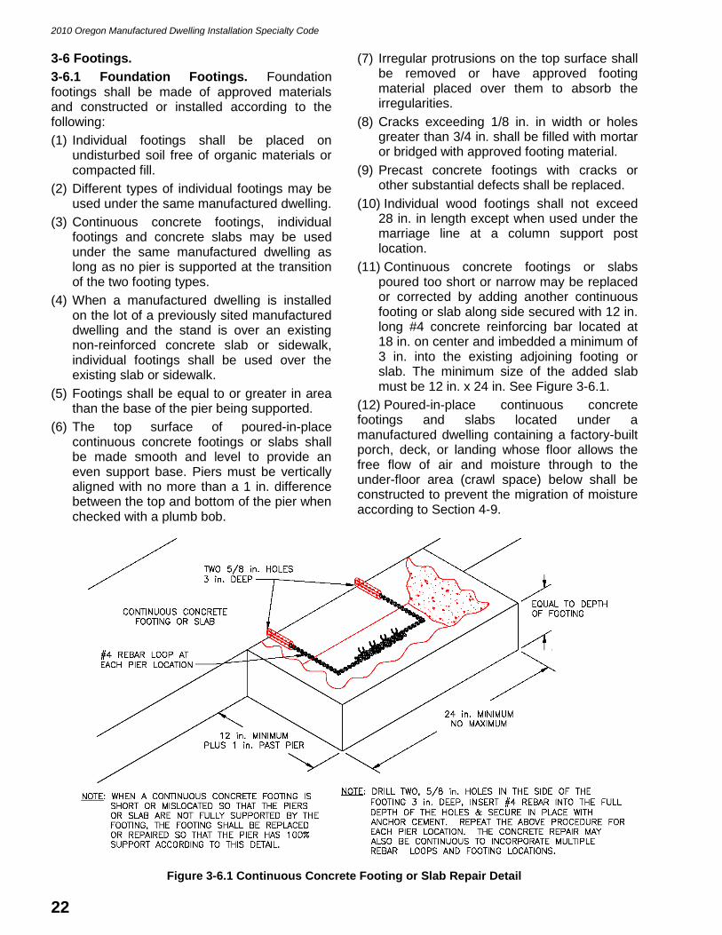
2010 Oregon Manufactured Dwelling Installation Specialty Code
22
3-6 Footings.
3-6.1 Foundation Footings. Foundation footings shall be made of approved materials and constructed or installed according to the following:
(1) Individual footings shall be placed on undisturbed soil free of organic materials or compacted fill.
(2) Different types of individual footings may be used under the same manufactured dwelling.
(3) Continuous concrete footings, individual footings and concrete slabs may be used under the same manufactured dwelling as long as no pier is supported at the transition of the two footing types.
(4) When a manufactured dwelling is installed on the lot of a previously sited manufactured dwelling and the stand is over an existing non-reinforced concrete slab or sidewalk, individual footings shall be used over the existing slab or sidewalk.
(5) Footings shall be equal to or greater in area than the base of the pier being supported.
(6) The top surface of poured-in-place continuous concrete footings or slabs shall be made smooth and level to provide an even support base. Piers must be vertically aligned with no more than a 1 in. difference between the top and bottom of the pier when checked with a plumb bob.
(7) Irregular protrusions on the top surface shall be removed or have approved footing material placed over them to absorb the irregularities.
(8) Cracks exceeding 1/8 in. in width or holes greater than 3/4 in. shall be filled with mortar or bridged with approved footing material.
(9) Precast concrete footings with cracks or other substantial defects shall be replaced.
(10) Individual wood footings shall not exceed 28 in. in length except when used under the marriage line at a column support post location.
(11) Continuous concrete footings or slabs poured too short or narrow may be replaced or corrected by adding another continuous footing or slab along side secured with 12 in. long #4 concrete reinforcing bar located at 18 in. on center and imbedded a minimum of 3 in. into the existing adjoining footing or slab. The minimum size of the added slab must be 12 in. x 24 in. See Figure 3-6.1.
(12) Poured-in-place continuous concrete footings and slabs located under a manufactured dwelling containing a factory-built porch, deck, or landing whose floor allows the free flow of air and moisture through to the under-floor area (crawl space) below shall be constructed to prevent the migration of moisture according to Section 4-9.
Figure 3-6.1 Continuous Concrete Footing or Slab Repair Detail

2010 Oregon Manufactured Dwelling Installation Specialty Code
23
3-6.2 Concrete. Footings may consist of one of the following:
(1) One 4 in. nominally thick individual precast concrete footing.
(2) One 3-1/2 in. thick poured-in-place individual concrete footing.
(3) Minimum 6 in. thick, continuous concrete footings (also known as concrete runners), not less than 18 in. wide and reinforced with two continuous minimum #4 reinforcement rods. Rods shall be:
(a) Overlapped 12 in.;
(b) connected with wire ties or equivalent;
(c) Be 3 in. from the bottom of the footing, and not closer than 3 in. from the edge of the footing; and
(d) Located 10 in. apart in the footing and the pair centered beneath the pier locations. If a continuous concrete footing is wide enough to support two or more rows of piers (i.e., a three-pad pour), the reinforcement rods shall be installed under each row of piers including the mainframe, perimeter, and marriage line piers. See Figures 3-6.2(a) and 3-6.2(b).
(4) Minimum of 3-1/2 in. thick continuous concrete slab footings (also known as a three-pad pour), not less than 48 in. wide, reinforced with approved fibers or with 10 gage 6 in. x 6 in. wire fabric centered vertically within the continuous footing and no closer than 1 in. from the edge of the continuous concrete slab footing. See Figure 3-6.2(c).
(5) Minimum 3-1/2 in. thick concrete slab (also known as a full slab) not less in area than the manufactured dwelling, reinforced with approved fibers or with 10 gage 6 in. x 6 in. wire fabric centered vertically within the slab and no closer than 1 in. from the edge of the slab. See Figure 3-6.2(d).
(6) Poured in place concrete shall have a minimum 28-day compressive strength of 3,000 lbs.
Figure 3-6.2(a) Typical Individual Continuous Concrete Footing
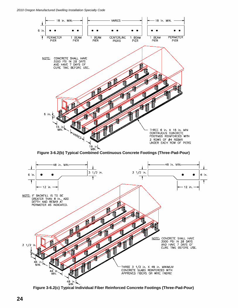
2010 Oregon Manufactured Dwelling Installation Specialty Code
24
Figure 3-6.2(b) Typical Combined Continuous Concrete Footings (Three-Pad-Pour)
Figure 3-6.2(c) Typical Individual Fiber Reinforced Concrete Footings (Three-Pad-Pour)
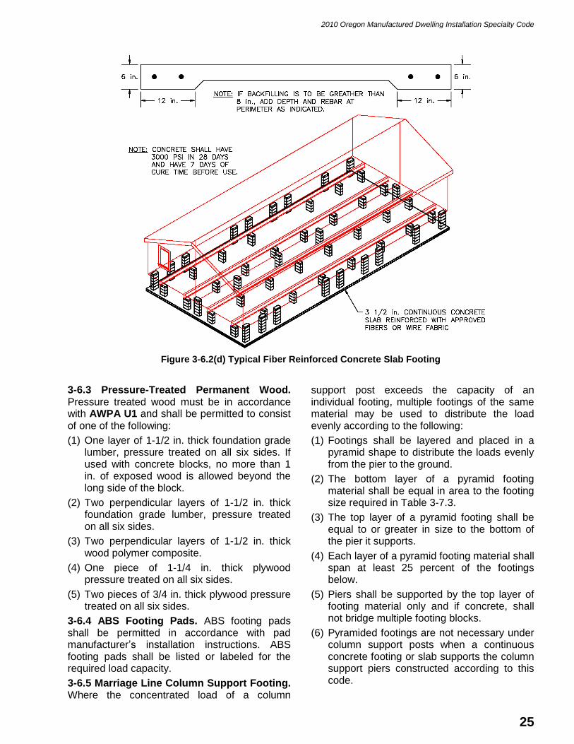
2010 Oregon Manufactured Dwelling Installation Specialty Code
25
Figure 3-6.2(d) Typical Fiber Reinforced Concrete Slab Footing
3-6.3 Pressure-Treated Permanent Wood. Pressure treated wood must be in accordance with AWPA U1 and shall be permitted to consist of one of the following:
(1) One layer of 1-1/2 in. thick foundation grade lumber, pressure treated on all six sides. If used with concrete blocks, no more than 1 in. of exposed wood is allowed beyond the long side of the block.
(2) Two perpendicular layers of 1-1/2 in. thick foundation grade lumber, pressure treated on all six sides.
(3) Two perpendicular layers of 1-1/2 in. thick wood polymer composite.
(4) One piece of 1-1/4 in. thick plywood pressure treated on all six sides.
(5) Two pieces of 3/4 in. thick plywood pressure treated on all six sides.
3-6.4 ABS Footing Pads. ABS footing pads shall be permitted in accordance with pad manufacturer’s installation instructions. ABS footing pads shall be listed or labeled for the required load capacity.
3-6.5 Marriage Line Column Support Footing. Where the concentrated load of a column
support post exceeds the capacity of an individual footing, multiple footings of the same material may be used to distribute the load evenly according to the following:
(1) Footings shall be layered and placed in a pyramid shape to distribute the loads evenly from the pier to the ground.
(2) The bottom layer of a pyramid footing material shall be equal in area to the footing size required in Table 3-7.3.
(3) The top layer of a pyramid footing shall be equal to or greater in size to the bottom of the pier it supports.
(4) Each layer of a pyramid footing material shall span at least 25 percent of the footings below.
(5) Piers shall be supported by the top layer of footing material only and if concrete, shall not bridge multiple footing blocks.
(6) Pyramided footings are not necessary under column support posts when a continuous concrete footing or slab supports the column support piers constructed according to this code.
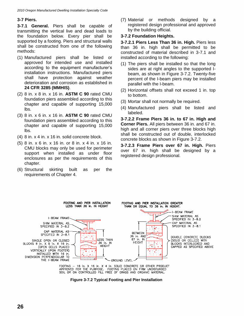
2010 Oregon Manufactured Dwelling Installation Specialty Code
26
3-7 Piers.
3-7.1 General. Piers shall be capable of transmitting the vertical live and dead loads to the foundation below. Every pier shall be supported by a footing. Piers and structural walls shall be constructed from one of the following methods:
(1) Manufactured piers shall be listed or approved for intended use and installed according to the equipment manufacturer’s installation instructions. Manufactured piers shall have protection against weather deterioration and corrosion as established in 24 CFR 3285 (MMHIS).
(2) 8 in. x 8 in. x 16 in. ASTM C 90 rated CMU foundation piers assembled according to this chapter and capable of supporting 15,000 lbs.
(3) 8 in. x 6 in. x 16 in. ASTM C 90 rated CMU foundation piers assembled according to this chapter and capable of supporting 15,000 lbs.
(4) 8 in. x 4 in. x 16 in. solid concrete block.
(5) 8 in. x 6 in. x 16 in. or 8 in. x 4 in. x 16 in. CMU blocks may only be used for perimeter support when installed as under floor enclosures as per the requirements of this chapter.
(6) Structural skirting built as per the requirements of Chapter 4.
(7) Material or methods designed by a registered design professional and approved by the building official.
3-7.2 Foundation Heights.
3-7.2.1 Piers Less Than 36 in. High. Piers less than 36 in. high shall be permitted to be constructed of material described in 3-7.1 and installed according to the following:
(1) The piers shall be installed so that the long sides are at right angles to the supported I-beam, as shown in Figure 3-7.2. Twenty-five percent of the I-beam piers may be installed parallel with the I-beam.
(2) Horizontal offsets shall not exceed 1 in. top to bottom.
(3) Mortar shall not normally be required.
(4) Manufactured piers shall be listed and labeled.
3-7.2.2 Frame Piers 36 in. to 67 in. High and Corner Piers. All piers between 36 in. and 67 in. high and all corner piers over three blocks high shall be constructed out of double, interlocked concrete blocks as shown in Figure 3-7.2.
3-7.2.3 Frame Piers over 67 in. High. Piers over 67 in. high shall be designed by a registered design professional.
Figure 3-7.2 Typical Footing and Pier Installation

2010 Oregon Manufactured Dwelling Installation Specialty Code
27
3-7.2.4 Elevated Homes. When more than 25 percent of the area of a home is installed so that the bottom of the main frame members are more than 36 in. above ground level, the home stabilizing devices shall be designed by a registered design professional.
3-7.3 Marriage Line Support.
3-7.3.1 Marriage Line Column Support Piers. For the initial installation of a new multisection manufactured dwelling, footings shall be sized and piers shall be placed under the column support locations according to the manufacturer’s installation instructions.
3-7.3.2. For secondary installations where the column support post location and capacity cannot be obtained or located, the column support post must be visually located and identified to determine that the spans and capacity of the piers and footings are according to Table 3-7.3. Column support may be placed parallel or perpendicular to the rim joist. If necessary, column support piers may be offset up to 6 in.
3-7.3.3 Marriage Line Concentrated Loads. Where the concentrated load of a column support post exceeds the capacity of a single pier, multiple piers of the same type and rating may be used to distribute the load. When two or more piers are used, each pier may be supported by individual footings having a combined size and rating equivalent to the applied load identified in Table 3-7.3.
3-7.4 Pier Location and Spacing.
3-7.4.1 General. Piers shall be spaced according to the following and Table 3-7.4.
3-7.4.2 Main Frame Piers. Piers shall be located under each main frame member within 12 in. from the end of each beam. All other piers under the main frame may be offset or placed as close as possible to accommodate foundation walls or other obstructions. Main frame piers shall not be offset more than 12 in. Up to 25 percent of the main frame CMU piers may be placed parallel to the beam.
3-7.4.3 Perimeter Piers. Perimeter piers shall be located on either side of each door over 30 in. wide, side wall window openings 4 ft. wide or greater, and recessed side wall openings 4 ft. wide or greater. Perimeter piers may be offset up to 12 in. and may be recessed up to 16 in. from the end wall.
Table 3-7.3 Center Beam Span and Footing Capacity for Secondary Installations
Footing Size 1,000 PSF
Soil/Span Capacity 1,250 PSF
Soil/Span Capacity 1,500 PSF
Soil/Span Capacity 2,300 PSF Concrete
Runner or Slab
256 SQ IN
1 – 16 in. x 16 in.
5 ft. – 6 in.
1,780 lbs.
6 ft. – 11 in.
2,225 lbs.
7 ft. – 9 in.
2,500 lbs.
12 ft. – 9 in.
4,094 lbs.
512 SQ IN
2 – 16 in. x 16 in.
11 ft. – 1 in.
3,560 lbs.
13 ft. – 10 in.
4,450 lbs.
15 ft. – 7 in.
5,000 lbs.
25 ft. – 7 in.
8,188 lbs.
768 SQ IN
3 – 16 in. x 16 in.
16 ft. – 8 in.
5,340 lbs.
20 ft. – 10 in.
6,675 lbs.
23 ft. – 2 in.
7,500 lbs.
38 ft. – 4 in.
12,282 lbs.
1,024 SQ IN
4 – 16 in. x 16 in.
22 ft. – 3 in.
7,120 lbs.
27 ft. – 9 in.
8,900 lbs.
31 ft. – 3 in.
10,000 lbs.
51 ft. – 2 in.
16,376 lbs.
1,536 SQ IN
6 – 16 in. x 16 in.
33 ft. – 4 in.
10,680 lbs.
41 ft. – 8 in.
13,350 lbs.
46 ft. – 10 in.
15,000 lbs. ------
2,048 SQ IN
8 – 16 in. x 16 in.
44 ft. – 6 in.
14,240 lbs.
55 ft. – 7 in.
17,800 lbs.
62 ft. – 6 in.
20,000 lbs. ------
NOTES:
(1) Piers may be placed directly on concrete runners or slabs and do not require additional footing materials to be placed.
(2) Other pier spacing is based on 256 square inch footings.

2010 Oregon Manufactured Dwelling Installation Specialty Code
28
Table 3-7.4 Pier Spacing
Pier Spacing 1,000 PSF
Soil Capacity
1,250 PSF
Soil Capacity
1,500 PSF
Soil Capacity
2,300 PSF Concrete Runner or Slab
Main Frame Piers 4 ft. – 6 in. 5 ft. – 6 in. 6 ft. – 0 in. 8 ft. – 0 in.
Perimeter Sidewall Piers 4 ft. – 6 in 5 ft. – 6 in. 6 ft. – 6 in. 8 ft. – 0 in.
Marriage Line Wall Piers 4 ft. – 6 in. 5 ft. – 6 in. 6 ft. – 6 in. 8 ft. – 0 in.
Marriage Line Floor Piers 8 ft. – 0 in. 8 ft. – 0 in. 8 ft. – 0 in. 8 ft. – 0 in.
NOTES:
(1) Pier spacing is based on 256 square inch footings.
(2) Perimeter piers are required at both sides of all doors and at any opening 4 ft. wide or greater.
(3) This table applies to the initial installation of homes having floors that are 14 ft. wide or less. Homes with floors over 14 ft. wide shall be installed according to the manufacturer’s installation instructions.
(4) For all secondary installations, piers shall be spaced according to this table.
(5) Perimeter piers are required on all homes, except when the distance from the I-beam to the perimeter of the home is less than 16 in.
3-7.5 Concrete Block Pier Configuration.
3-7.5.1. Concrete block piers shall be installed in accordance with the following: Figure 3-7.2.
(1) The concrete blocks shall be stacked with their hollow cells aligned vertically.
(2) When piers are constructed of blocks stacked side by side, each layer shall be at right angles to the preceding one.
3-8 Pier Caps, Shims and Wedges.
3-8.1 Pier Caps. Structural loads shall be evenly distributed across capped hollow block piers. Material shall be equal in size to the pier blocks. Piers shall be constructed from one of the following:
(1) A 4 in. nominally thick solid concrete block;
(2) A 1 in. nominally thick group 2 or 3 parallel laminated veneer wood plate;
(3) One piece of 1-1/4 in. plywood;
(4) Two pieces of 3/4 in. plywood;
(5) One 1-1/2 in. thick S-P-F (Spruce-Pine-Fir) or better board lumber free of loose knots, splits, or other visual defects;
(6) One 1-1/2 in. thick wood polymer composite;
(7) Listed and approved prefabricated pier caps; or
(8) Material or methods designed by a registered design professional and approved by the building official.
3-8.2 Pier Shims. Pier shims for CMU block foundation piers shall be a minimum of 5-1/2 in. x 16 in. constructed using any of the following materials, but shall not exceed a combined height of 9 in.:
(1) 1 in. thick group 2 or 3 parallel laminated veneer wood plate;
(2) 1/4 in. or greater plywood;
(3) One 1-1/2 in. thick S-P-F (Spruce-Pine-Fir) or better board lumber free of loose knots, splits, or other visual defects;
(4) 3/4 in. thick S-P-F (Spruce-Pine-Fir) or better board lumber free of loose knots, splits, or other visual defects;
(5) 1-1/4 in. minimum thick wood polymer composite;
(6) 4 in. x 6 in. wood beam;
(7) Listed and approved shimming material; or
(8) Material or methods designed by a registered design professional and approved by the building official.
3-8.3 Wedges. Wedges for CMU block foundation piers shall be made with one of the following materials, but shall not exceed a combined height of 9 in.:
(1) Two sets of 3/4 in. thick by 3-1/2 in. wide by 8 in. to 16 in. long wood wedges;
(2) One set of 1-1/2 in. thick by 3-1/2 in. wide by 8 in. to 16 in. long wood wedges;
(3) Listed or approved shimming material; or
(4) Material or methods designed by a registered design professional and approved the building official.
3-9 Perimeter Piers.
3-9.1 Perimeter Piers. Perimeter piers may be recessed under the sidewalls, up to 12 in., to allow room for skirting to be constructed or installed. When foundation walls, basement

2010 Oregon Manufactured Dwelling Installation Specialty Code
29
walls, or structural skirting walls are used for support, recessed perimeter piers are not required.
3-9.2 Recessed Perimeter Piers. Recessed perimeter piers shall be listed or approved prefabricated foundation piers or rated CMU piers installed according to the following:
(1) On manufactured dwellings with transverse floor systems (floor joists perpendicular to the main frame), the recessed perimeter piers shall support a single 4 in. x 4 in. horizontal wood beam, or two 2 in. x 4 in. dimensional lumber nailed together, or equal, spanning a minimum of two transverse floor joists. See Figure 3-9.2(a).
(2) On manufactured dwellings with longitudinal floor systems (floor joists parallel with the main frame), the recessed perimeter piers shall support the floor joists outside the main frame. A 4 in. x 4 in. horizontal wood beam, or two 2 in. x 4 in. dimensional lumber nailed together, or equal, spanning each floor joist may be located on the outer side of the main frame. The beam shall fit tight against the bottom of the top flange of the main frame. See Figure 3-9.2(b).
(3) Perimeter piers may be recessed so the bearing point of a concrete block or a prefabricated pier is no more than 12 in. from the perimeter of the manufactured dwelling.
(4) Recessed perimeter piers shall be centered beneath the horizontal beams.
(5) A 4 in. x 4 in. horizontal wood beam or two 2 in. x 4 in. dimensional lumber nailed together and placed on edge, spanning each floor joist, shall be placed against the floor.
(6) Recessed perimeter piers shall support the horizontal beams in a level position so that the beam is tight against the bottom of each floor joist.
(7) Recessed perimeter piers shall provide a tight fit between the top of the pier and the bottom of the horizontal beams in a manner that does not allow rocking or other movement.
Figure 3-9.2(a) Typical Recessed Pier Detail for Transverse Floors

2010 Oregon Manufactured Dwelling Installation Specialty Code
30
Figure 3-9.2(b) Typical Recessed Pier Detail for Longitudinal Floors
3-10 Chassis.
3-10.1 Chassis Removal. Except for wheels, tires, axles, hitches, transportation lights, and those parts of the chassis specifically made to be removed to accommodate the foundation, no portion of a manufactured dwelling chassis shall be removed before, during, or after the manufactured dwelling installation.
3-10.2 Chassis Alteration. Alterations or modifications to the chassis may only be performed according to plans approved by the DAPIA or designed by a registered design professional, and with the approval of the Building Codes Division.

2010 Oregon Manufactured Dwelling Installation Specialty Code
31
CHAPTER 4
UNDER-FLOOR ENCLOSURES
4-1 General.
4-1.1. All manufactured dwellings shall have the under-floor area enclosed with skirting installed according to this code. Skirting is not required for manufactured dwellings installed in flood hazard areas.
4-2 Skirting Material.
4-2.1. Skirting shall be constructed of a durable rigid material such as painted wood, exterior grade wood composites, exterior grade plywood, vinyl, aluminum, steel, foam, masonry, cement board, concrete or other material acceptable to the building official.
4-2.2. Skirting shall meet the following:
(1) Skirting materials shall be manufactured and intended for exterior use.
(2) Non-structural skirting shall not be used to support any loads except as necessary to carry its own weight and to resist the elements.
(3) Skirting shall be self-supporting but may be attached to the bottom of the manufactured dwelling floor for stability.
(4) Skirting shall be adequately secured to assure stability and to minimize vibration and susceptibility to wind damage.
(5) Skirting shall be installed to compensate for possible frost heave and settling but is not required to have a footing located at or below the frost line.
(6) Holes or gaps below the skirting shall be sealed to resist air and water infiltration.
(7) Skirting shall be designed to resist the entrance of moisture and rodents into the under-floor area.
(8) Skirting transitions between the skirting and the bottom of the home shall be attached in a manner that does not trap water between the skirting and the home siding or trim.
(9) The transition from the siding on the home to the skirting shall be weather sealed to prevent water migration behind the transition board or into the crawl space.
(10) All under-floor enclosures that retain over 8 in. of backfill must be water proofed below grade around the perimeter of the home.
4-3 Foundation Walls.
4-3.1. Foundation walls may be used in place of recessed perimeter piers, skirting, marriage line column support piers under the end walls, anchoring, and to support the horizontal pressures of backfill around the manufactured dwelling. Foundation walls shall be constructed according to this code and where not specific, to the Oregon Residential Specialty Code. Concrete based foundation walls can hold up to 48 in. of backfill. Lumber framed foundation walls can hold up to 36 in. of backfill.
4-3.2. Foundation walls, when used, shall be constructed according to the following and Figures 4-3.2(a), 4-3.2(b) and 4-3.2(c):
(1) Foundation walls shall be constructed of poured-in-place concrete, concrete masonry units (CMUs), foundation grade lumber, insulated concrete forms, or an approved or listed prefabricated perimeter foundation wall system.
(2) A minimum 6 in. thick, continuous concrete footing, not less than 12 in. wide reinforced with two continuous minimum #4 reinforcement rods. Rods shall be lapped 12 in., connected with wire ties or equal, be 3 in. from the bottom of the footing, and not closer than 3 in. from the edge of the footing.
(3) Foundation walls shall provide a tight fit to the bottom of the manufactured dwelling floor framing. Shimming may be permitted between outriggers and other permanent obstructions.
(4) Foundation walls or footings shall be secured to the manufactured dwelling.
(5) The stand shall be a minimum of 12 in. above the base flood elevation (BFE) according to the Flood Insurance Rate Map (FIRM) unless the foundation wall is opened on one side or end so that floodwater cannot be trapped.
(6) All under-floor enclosures that retain over 8 in. of backfill and where ground water may present a detrimental condition, one or more of the following must be done and the building official shall require any or all of the following:
(a) Foundation walls water proofed around the perimeter of the manufactured dwelling;
(b) A perimeter drain around the foundation wall to divert water away from the manufactured dwelling; or
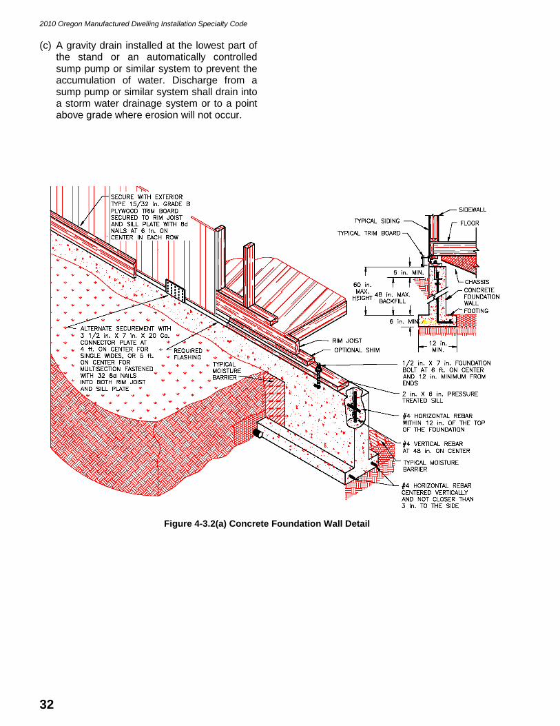
2010 Oregon Manufactured Dwelling Installation Specialty Code
32
(c) A gravity drain installed at the lowest part of the stand or an automatically controlled sump pump or similar system to prevent the accumulation of water. Discharge from a sump pump or similar system shall drain into a storm water drainage system or to a point above grade where erosion will not occur.
Figure 4-3.2(a) Concrete Foundation Wall Detail

2010 Oregon Manufactured Dwelling Installation Specialty Code
33
Figure 4-3.2(b) CMU Foundation Wall Detail
Figure 4-3.2(c) Pressure Treated Lumber Foundation Wall Detail
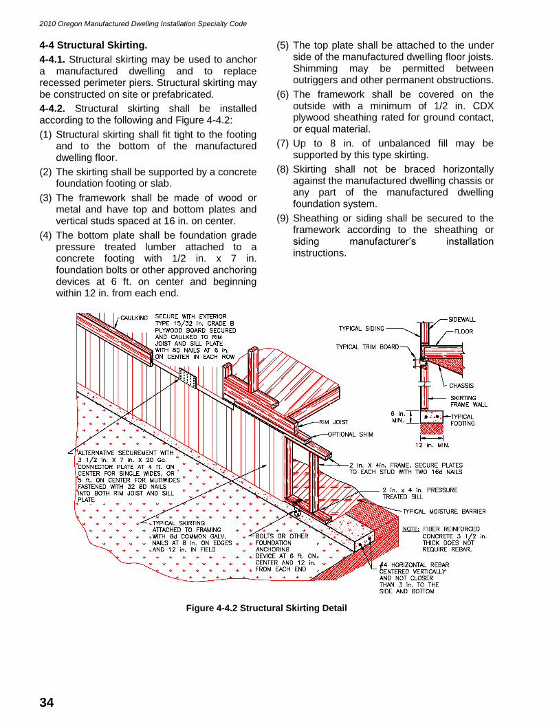
2010 Oregon Manufactured Dwelling Installation Specialty Code
34
4-4 Structural Skirting.
4-4.1. Structural skirting may be used to anchor a manufactured dwelling and to replace recessed perimeter piers. Structural skirting may be constructed on site or prefabricated.
4-4.2. Structural skirting shall be installed according to the following and Figure 4-4.2:
(1) Structural skirting shall fit tight to the footing and to the bottom of the manufactured dwelling floor.
(2) The skirting shall be supported by a concrete foundation footing or slab.
(3) The framework shall be made of wood or metal and have top and bottom plates and vertical studs spaced at 16 in. on center.
(4) The bottom plate shall be foundation grade pressure treated lumber attached to a concrete footing with 1/2 in. x 7 in. foundation bolts or other approved anchoring devices at 6 ft. on center and beginning within 12 in. from each end.
(5) The top plate shall be attached to the under side of the manufactured dwelling floor joists. Shimming may be permitted between outriggers and other permanent obstructions.
(6) The framework shall be covered on the outside with a minimum of 1/2 in. CDX plywood sheathing rated for ground contact, or equal material.
(7) Up to 8 in. of unbalanced fill may be supported by this type skirting.
(8) Skirting shall not be braced horizontally against the manufactured dwelling chassis or any part of the manufactured dwelling foundation system.
(9) Sheathing or siding shall be secured to the framework according to the sheathing or siding manufacturer’s installation instructions.
Figure 4-4.2 Structural Skirting Detail

2010 Oregon Manufactured Dwelling Installation Specialty Code
35
4-5 Non-Structural Skirting.
4-5.1 Non-Structural Wood Skirting. Non-structural wood skirting shall be installed according to the following and Figure 4-5.1:
(1) Skirting constructed on site with sheathing or siding material shall be supported by a wood or metal framework. The framework shall have top and bottom horizontal rails or plates and shall have vertical members at 16 in. on center.
(2) Wood framing material shall not be located within 5-1/2 in. of the ground except when separated and protected from the earth with 3 in. of metal, concrete, or wood polymer composite and a layer of 15 pound felt roofing underlayment, or when the wood is pressure treated foundation grade lumber.
(3) Top horizontal rails may be fastened to the bottom of the manufactured dwelling floor for support.
(4) Bottom horizontal rails may be eliminated when steel or fiberglass stakes are fastened to each vertical member and driven into the ground with a minimum penetration of 6 in. into firm soil, 18 in. into soft soil, or as necessary to secure the frame work and skirting in place.
(5) Up to 8 in. of unbalanced fill may be supported by this type of skirting.
(6) Skirting made of cement board, untreated plywood, and wood composite materials shall not be located within 5-1/2 in. of the ground except when separated from the earth by 3 in. of metal, concrete, or wood polymer composite and a layer of 15 pound felt roofing underlayment. Only cement board specifically approved for ground contact may be in direct contact with the ground.
(7) Skirting shall not be braced horizontally against the manufactured dwelling chassis or any part of the manufactured dwelling foundation system.
(8) Sheathing or siding shall be secured to the framework according to the sheathing or siding manufacturer’s installation instructions.
(9) Recessed perimeter support piers are required with this type of skirting and shall be spaced as per Table 3-7.4.
(10) Materials making ground contact shall be tested and approved for ground contact.
Figure 4-5.1 Non-Structural Wood Skirting Detail
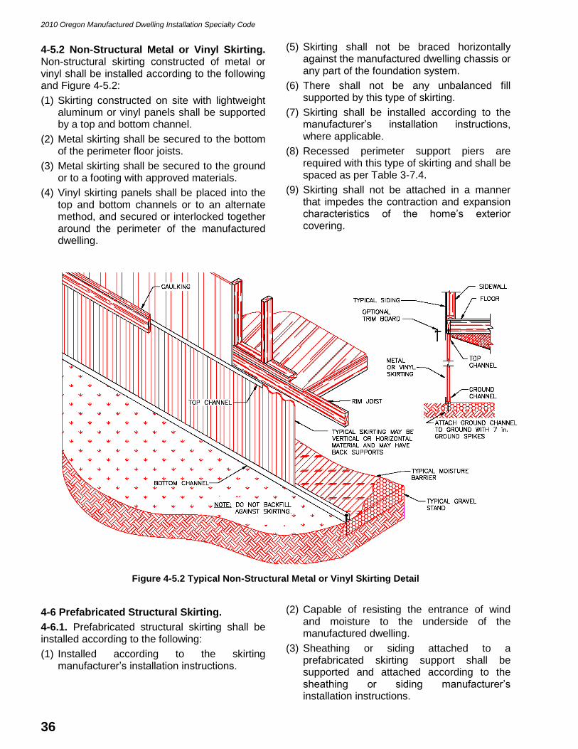
2010 Oregon Manufactured Dwelling Installation Specialty Code
36
4-5.2 Non-Structural Metal or Vinyl Skirting. Non-structural skirting constructed of metal or vinyl shall be installed according to the following and Figure 4-5.2:
(1) Skirting constructed on site with lightweight aluminum or vinyl panels shall be supported by a top and bottom channel.
(2) Metal skirting shall be secured to the bottom of the perimeter floor joists.
(3) Metal skirting shall be secured to the ground or to a footing with approved materials.
(4) Vinyl skirting panels shall be placed into the top and bottom channels or to an alternate method, and secured or interlocked together around the perimeter of the manufactured dwelling.
(5) Skirting shall not be braced horizontally against the manufactured dwelling chassis or any part of the foundation system.
(6) There shall not be any unbalanced fill supported by this type of skirting.
(7) Skirting shall be installed according to the manufacturer’s installation instructions, where applicable.
(8) Recessed perimeter support piers are required with this type of skirting and shall be spaced as per Table 3-7.4.
(9) Skirting shall not be attached in a manner that impedes the contraction and expansion characteristics of the home’s exterior covering.
Figure 4-5.2 Typical Non-Structural Metal or Vinyl Skirting Detail
4-6 Prefabricated Structural Skirting.
4-6.1. Prefabricated structural skirting shall be installed according to the following:
(1) Installed according to the skirting manufacturer’s installation instructions.
(2) Capable of resisting the entrance of wind and moisture to the underside of the manufactured dwelling.
(3) Sheathing or siding attached to a prefabricated skirting support shall be supported and attached according to the sheathing or siding manufacturer’s installation instructions.

2010 Oregon Manufactured Dwelling Installation Specialty Code
37
(4) Unless specifically allowed by the manufacturer’s installation instructions, there shall be no unbalanced fill in excess of 8 in. supported by prefabricated skirting. Such designed backfill provision may not transfer any horizontal loading to the manufactured dwelling, and must be supported solely by the skirting structure.
(5) Prefabricated skirting may take the place of recessed perimeter pier supports if the skirting is rated for a 4,000 pound design load, supported on a minimum 256 square inch footing, and spaced according with Table 3-7.4 or a concrete runner or slab. If the skirting manufacturer allows unbalanced fill in excess of 8 in. to be supported by the prefabricated skirting, the concrete runner or slab shall be installed according to Section 4-3.
(6) Prefabricated structural skirting that retains over 8 in. of backfill must be waterproofed below grade around the perimeter of the home.
4-7 Masonry Block Skirting.
4-7.1 Masonry Block Skirting. Masonry block skirting shall be installed according to the following and Figure 4-7.1:
(1) Masonry block skirting shall be made with concrete masonry units, cinder block, pumice block, brick, block, or stone, and shall be a minimum of 4 in. thick. Masonry block skirting is not required to be rated for structural strength if it is not being used as perimeter support.
(2) Masonry block skirting shall be supported by and mortared to a concrete footing a minimum of 12 in. wide by 6 in. deep, or on a footing described in Section 3-6 if used for perimeter support.
(3) Masonry block skirting shall be mortared at each joint or dry stacked and filled with concrete, or dry stacked and interlocked when manufactured with an interlocking system.
(4) Masonry block skirting may support up to 8 in. of unbalanced fill without having to be constructed as a foundation wall or retaining wall.
(5) Masonry block skirting may take the place of the recessed perimeter pier supports if constructed with ASTM C 90 rated concrete block, capped with a pier cap, and shimmed up to the bottom of the floor at each location required in Table 3-7.4.
Figure 4-7.1 Concrete Masonry Block (CMU) Skirting Detail

2010 Oregon Manufactured Dwelling Installation Specialty Code
38
4-8 Concrete Masonry Unit Retaining Wall Skirting.
4-8.1. Concrete masonry unit (CMU) retaining walls may be used to take the place of skirting and to support the horizontal pressures of backfill around the manufactured dwelling.
4-8.2. CMU retaining walls shall be installed according to the following and Figure 4-8.2:
(1) CMU retaining walls shall be constructed with ASTM C 90 rated concrete block.
(2) CMU retaining walls that retain over 8 in. of backfill must be waterproofed below grade around the perimeter of the home.
(3) CMU retaining wall footings shall be supported by 12 in. x 6 in. deep concrete with #4 horizontal rebar centered vertically and not closer than 3 in. to the side and 3 in. from the bottom.
(4) CMU retaining walls shall be self supporting.
(5) CMU blocks shall be mortared at each joint and to the concrete footing.
(6) CMU blocks a minimum of 8 in. x 8 in. x 16 in. are not required to be grout or concrete filled. CMU blocks less than 8 in. in width shall be grout or concrete filled with a vertical #4 rebar installed from within the footing to the top of the foundation every 48 in., and a continuous #4 horizontal rebar within 8 in. of the top of the foundation.
(7) CMU retaining walls may support up to 28 in. of unbalanced fill.
(8) CMU retaining walls may take the place of the recessed perimeter pier supports if capped with a pier cap and shimmed up to the bottom of the floor at each location required in Table 3-7.4.
(9) CMU retaining walls shall not be braced off of any part of the manufactured dwelling or manufactured dwelling.
Figure 4-8.2 Concrete Masonry Unit (CMU) Retaining Wall Skirting Detail

2010 Oregon Manufactured Dwelling Installation Specialty Code
39
4-9 Under-Floor Separations.
4-9.1. Manufactured dwellings shall be installed to provide a separation between the under-floor areas of porches, decks, landings or other similar structures, including factory built structures, to the underside of the home to prevent the migration of moisture to the underside of the home.
4-9.2. The separation shall be made according to one of the following:
(1) An under-floor enclosure shall be placed below the recessed exterior walls of the manufactured dwelling, see Figure 4-9.2;
(2) An under-floor enclosure shall be placed below the outside perimeter of the porch,
deck, landing, or similar structure. A durable, rigid or flexible, curtain wall material (i.e. sheet vinyl, plexiglas, fiberglass, rubber membrane, ABS, pressure treated wood, 6 mil polyethylene membrane sheeting, or EPDM (ethylene propylene diolefin monomer) is placed below the recessed exterior walls of the manufactured dwelling. For the purposes of this code, EPDM is a rubber sheeting used to prevent water penetration in roofing, foundations and other similar applications where moisture or water penetration must be eliminated or minimized; or
(3) A barrier at the footing to prevent water migration into the crawl space.
Figure 4-9.2 Under-Floor Separations
4-10 Under-Floor Ventilation.
4-10.1 Under-Floor Ventilation. The enclosed under-floor area of a manufactured dwelling shall be vented. Foundation walls, perimeter retaining walls, basements and skirting shall be vented as follows:
(1) Each manufactured dwelling shall have cross ventilation on at least two sides of the home.
(2) There shall be a minimum of four ventilation openings provided through the under-floor enclosure.
(3) When possible ventilation openings shall begin at or within 3 ft. of a corner and then be evenly spaced.
(4) Ventilation openings shall not be located at marriage lines or where the free flow of air would be restricted or obstructed.
(5) Ventilation openings shall be placed as high as possible. In flood hazard areas, the vent openings shall be located within 12 in. of the interior grade.
(6) Ventilation openings may be of a closable type for seasonal climatic conditions unless the stand is located at or below the base flood elevation in which case closable vents are prohibited.

2010 Oregon Manufactured Dwelling Installation Specialty Code
40
(7) Ventilation openings shall be provided with maximum 1/4 in. corrosion-resistant wire mesh or with louvered openings with not less than 1/8 in. screen to retard the entry of vegetation, waste materials, and rodents.
(8) Ground level installations shall have vent wells installed where backfill or pavement would otherwise block the vent opening.
(9) Under-floor vents may be omitted when the manufactured dwelling is placed over a basement containing a living area.
4-10.2 Ventilation Sizing. The under-floor net free ventilation area shall be:
(1) Equivalent to 1 square foot for every 1,500 square feet of under-floor area, as per Table 4-10.2.
(2) When a vent does not include a rating of the net free area, deduct 25 percent of the gross ventilation area for vent hardware such as screens or louvers.
(3) Under-floor vents may be omitted when a continuously operated mechanical ventilation system is provided. A minimum air flow rate of 1.0 CFM for each 50 square feet of under-floor area shall be maintained and an equally sized air intake port at the opposite end of the home shall be provided.
Table 4-10.2 Ventilation Sizing Table
Type of Home Min. # Vents Required Min. Free Area Required
Singe Wide 4 90 sq. in.
Double Wide 4 180 sq. in.
Triple Wide 4 280 sq. in.
Quad 4 380 sq. in.
NOTES: (1) More vents than the minimum required may be installed to achieve the minimum free area. (2) The minimum free area required is provided as a guide for a typical type of home being vented. The
actual amount of free area required may be determined by calculation as per 4-10.2.
4-11 Under-Floor Access.
4-11.1. Access to the under-floor area of a manufactured dwelling shall be provided according to this section.
4-11.1.1 Skirting Access. Access through the skirting shall be as follows:
(1) Access opening shall provide a minimum clear opening of 18 in. x 24 in.
(2) Access doors or panels that are not easily recognizable shall be permanently labeled “ACCESS” in 3/4 in. high bold letters.
(3) There shall be a minimum 6 in. x 6 in. covered hand hole access opening through the under-floor enclosure within reach and not more than 12 in. from the main water inlet shutoff valve and the main drain cleanout if either is located in the enclosed area under the manufactured dwelling.
4-11.1.2 Ground Level Access. Foundation walls, retaining walls, and some basement walls shall be provided with an under-floor ground level access well constructed according to the following, see Figure 4-11.1.2:
(1) The access well shall be constructed with materials approved for supporting unbalanced fill to the depth of the access well below grade.
(2) The access shall provide a minimum clear opening of 18 in. x 24 in. through the foundation wall, retaining wall, or basement wall to the underside of the manufactured dwelling.
(3) The access well shall have a minimum inside horizontal dimension of 24 in. x 30 in. Measurements shall be taken from the outside face of the access opening.
(4) The bottom of the access well shall be below the threshold of the access opening.
(5) The access well shall have a removable water resistive cover weighing not more than 50 lbs., made to resist the entrance of rodents and animals, without a locking device, and have handles or a method of opening without the use of special tools.

2010 Oregon Manufactured Dwelling Installation Specialty Code
41
Figure 4-11.1.2 Typical Ground Level Ventilation and Under-Floor Access Detail
4-11.1.3 Through the Floor Access. Access to the under-floor area through the floor of a manufactured dwelling shall:
(1) Be constructed according to the manufacturer’s approved DAPIA plans.
(2) Have a minimum clear opening of 24 in. x 30 in.
(3) Have an access panel that is tight fitting, capable of resisting rodents, and insulated with an R-value equivalent to the insulation within the floor cavity.
(4) Have an access panel weighing not more than 50 lbs. with a handle or method of opening that does not require the use of tools.
(5) Have a minimum 24 in. x 30 in. x 48 in. space directly above the access panel without any permanent obstructions.
(6) Be made available for inspectors and service personnel.
4-11.1.4 Stairway Access Through the Floor. Stairways within a manufactured dwelling shall comply with the following:
(1) Access openings through the manufactured dwelling floor or ceiling for stairways shall be constructed according to the manufacturer’s approved DAPIA plans.
(2) Stairways, landings, guardrails, handrails, and headroom used for access to a basement, second floor, or between multi-level floors shall be constructed and installed according to the Oregon Residential Specialty Code whether constructed on site or in the factory.

2010 Oregon Manufactured Dwelling Installation Specialty Code
42
CHAPTER 5
INSTALLATION PROCEDURES
5-1 Marriage Line Connection and Seal.
5-1.1 Interconnection of Multisection Manufactured Dwellings. The interconnection of multisection manufactured dwellings shall be completed in accordance with the following.
5-1.2 Preparation. Prior to joining the sections of a multi-section manufactured dwelling:
(1) Remove all shipping and close-up materials from the marriage line floor, wall, and roof areas between the sections so there are no exposed or protruding fasteners, material scraps, or other protrusions on either side of the marriage line.
(2) Install a durable, non-porous caulking, closed cell foam, urethane, or sill seal on the floor, wall, and roof areas of the marriage line between each section. See Figure 5-1.2.
(3) Caulking, when used, shall be capable of compressing and stretching.
(4) Sill seal, if used, shall be a minimum of 5-1/2 in. wide, doubled over, and attached with fasteners staggered at 6 in. on center.
(5) Gaps between multisection manufactured dwellings shall be shimmed with wood shims, expansive foam, or other air infiltration barrier listed in this section. Gaps larger than 1 in. must be shimmed with full depth wood at the bolt locations. Gaps larger than 1-1/2 in. shall be referred to the manufacturer for correction.
Figure 5-1.2 Typical Marriage Line Seal
5-2 Marriage Line Attachments.
5-2.1. Marriage line attachments shall be secured according to this section.
5-2.1.1 Ridge Beam Connections. Multisection manufactured dwellings marriage line ridge beams shall be secured together according to one of the following:
(1) With 1/2 in. diameter bolts and washers, spaced equally along the length of the ridge beam, and at a maximum of 32 in. on center. Bolts shall be long enough to penetrate through both beams, washers, and all shimming material, and have 1 in. of exposed thread for installing the nut. Bolts shall be installed through 5/8 in. diameter pre-drilled holes 2 in. below the top of the ridge beam, at a 90 degree angle to the beam.
(2) With 3/8 in. diameter lag screws installed with washers, spaced equally and staggered side to side the length of the ridge beam and at a maximum of 16 in. on center. Lag screws shall be long enough to penetrate through both ridge beams. Lag screws shall be installed through pre-drilled pilot holes with a diameter equal to half the diameter of the lag screw. Lag screws shall be installed at a 45 to 90 degree angle.
(3) When permitted by the manufacturer’s installation instructions, with 1-1/2 in. wide, by 10 in. long, by 30 gage galvanized steel straps spaced equally along the length of the ridge beam at a maximum of 32 in. on center and fastened into the top chords of the rafters or trusses on each side of the ridge beam with three #8 by 1 in. wood screws at each end of each strap.

2010 Oregon Manufactured Dwelling Installation Specialty Code
43
(4) Ridge beam column support locations on an initial installation shall be secured according to the manufacturer’s installation instructions. For secondary installations where a ridge beam column support post is located only on one side of a marriage line, install eight 1/2 in. diameter bolts with washers or ten 3/8 in. lag screws through both ridge beams, spaced at 2 to 4 in. on center horizontally, and centered over each applicable column support post. Use the same fastening specifications identified in (1) or (2) of this subsection.
(5) In addition to the ridge beam securement methods in subsections (1) through (4) of this section, the ridge beams may also be secured from the ceiling side.
(6) Marriage line fasteners (i.e. bolts, lag screws, and wood screws) shall only be installed in areas where there is solid ridge beam material or equal between the sections.
(7) Where it is not possible to secure the beams according to these instructions, secure according to the manufacturer’s installation instructions.
5-2.1.2 Wall Connections. Multisection manufactured dwelling marriage line walls shall be secured together at the ends of each adjoining wall section according to the following:
(1) End walls shall be:
(a) Secured with #10 wood screws, spaced equally at 12 in. on center on one side or staggered from side to side of the mating studs to 6 in. of the floor and ceiling; or
(b) Secured with 3/8 in. diameter lag screws installed with washers, spaced equally and staggered from side to side of the mating studs at a maximum of 24 in. on center. Lag screws shall be sized long enough to penetrate 2 in. into the adjoining stud on both sides of the marriage line walls. Lag screws shall be installed through pre-drilled pilot holes with a diameter equal to half the diameter of the lag screw; and
(2) Interior marriage line walls shall be secured with # 8 wood screws, spaced equally at 16 in. on center on one side or staggered from side to side of the mating studs to 8 in. of the floor and ceiling.
5-2.1.3 Floor Connections. Multisection manufactured dwelling marriage line floors shall be secured together according to one of the following:
(1) With 1/2 in. diameter bolts and washers installed through each marriage clip under the floor and drawn tight with a nut when the marriage line clips are welded to the chassis outriggers.
(2) With 3/8 in. diameter lag screws installed with washers, spaced equally and staggered from side to side of the mating joists 24 in. on center. Lag screws shall be installed into the rim joists at a 45 to 90 degree angle. Lag screws shall be sized long enough to penetrate through both rim joists. Lag screws shall be installed through pre-drilled pilot holes with a diameter equal to half the diameter of the lag screw.
(3) With #10 wood screws, spaced equally, and staggered from side to side of the mating joists 12 in. on center. Wood screws shall be installed into the floor rim joists at a 45 to 90 degree angle. Wood screws shall be sized long enough to penetrate through both rim joists.
5-3 Weather Seal.
5-3.1. All joints between multisection manufactured dwellings sections shall be sealed and weather-stripped.
5-3.1.1 Roof Seal. Multisection manufactured dwelling roofs shall be sealed according to the following:
(1) Roofing at the marriage line seam shall be sealed with 10 in. wide roofing underlayment centered over the seam the entire length of the roof.
(2) The roof cap shall be attached according to the roofing manufacturer’s installation instructions. Field installed shingled roof caps (hip and ridge shingles) shall be oriented with respect to the prevailing winds.
(3) Ceilings at the marriage line seam shall be sealed with material of the same type and thickness as the ceiling material or covered with wood or foam molding attached with appropriate fasteners.

2010 Oregon Manufactured Dwelling Installation Specialty Code
44
(4) Holes from shipping material fasteners in the roofing material shall be sealed with approved roofing cement. Sealant shall be placed under the shingles or if exposed shall be of the same color as the roofing material.
(5) All damaged roofing shall be replaced with a like material.
(6) All roofing material shall be installed according to the roofing manufacturer’s installation instructions.
(7) All roof penetrations for site installed plumbing vents, mechanical vents, or chimneys shall be sealed according to this code and the product manufacturer’s installation instructions.
(8) Marriage line ridge caps utilizing ridge ventilation systems shall be installed according to the ventilation system installation instructions.
5-3.1.2 Wall Seal. Multisection manufactured dwelling marriage line walls shall be sealed according to the following:
(1) Exterior wall seams at the marriage line shall be closed up with siding material rated for exterior exposure.
(2) All damaged siding shall be repaired according to the manufacturer’s instructions or replaced with material rated for exterior exposure.
(3) All wall penetrations for mechanical, electrical, gas, or plumbing equipment, fixtures or devices shall be sealed.
(4) All insulation removed or displaced during the installation and testing of the manufactured dwelling shall be put back in place.
(5) All access panels shall be attached in place.
(6) Doors and windows shall be adjusted, squared, secured in place, sealed, and made operational.
(7) Damage to doors or windows affecting their operation or thermal performance shall be repaired or replaced.
5-3.1.3 Floor Seal. Multisection manufactured dwelling floors shall be sealed according to the following:
(1) Floor surfaces shall be made smooth, flush, and level before finish-flooring material is installed.
(2) All floor decking penetrations for mechanical, electrical, gas, or plumbing equipment, fixtures or devices shall be sealed.
(3) All insulation removed or displaced during the installation and testing of the manufactured dwelling shall be put back in place.
(4) All access panels shall be attached in place.
(5) All cuts, holes or tears in the bottom board or floor insulation including but not limited to areas around structural connections, plumbing, mechanical, electrical, gas, and heating equipment penetrations shall be adequately repaired or sealed to resist the entrance of rodents.

2010 Oregon Manufactured Dwelling Installation Specialty Code
45
CHPATER 6
ELECTRICAL CONNECTIONS
6-1 General.
6-1.1. All electrical equipment and installations shall be designed, constructed, and installed in accordance with this code and where not specific, to the applicable provisions of the Oregon Electrical Specialty Code.
6-2 Electrical Feeders.
6-2.1. Manufactured dwelling feeder conductors shall consist of one of the following:
(1) A listed power cord either factory installed or shipped loose and installed as per the manufacturer’s installation instructions and this code;
(2) A permanently installed overhead feeder containing four insulated conductors listed for use and sized according to Table 6-2.1(a);
(3) A permanently installed overhead feeder containing three insulated conductors listed for use and sized according to Table 6-2.1(a). An “uninsulated” messenger of a factory assembled quadraplex cable shall be installed in compliance with the applicable provisions of Oregon Electrical Specialty Code, Articles 230.24, 230.32, and 550-10;
(4) A permanently installed underground feeder containing four insulated conductors listed for use and sized according to Table 6-2.1(b);
(5) A permanently installed feeder installed by the manufacturer according to DAPIA approved plans when the service equipment is mounted on the manufactured dwelling by the manufacturer at the manufacturing facility; or
(6) A permanently installed feeder containing four insulated conductors and protected in an approved raceway in or through the floor, wall, or roof or under the chassis when the service equipment is mounted on the manufactured dwelling on site.
6-2.2 Feeder Sizing. The feeder size shall be based on the amperage of the main circuit breaker inside the manufactured dwelling’s main distribution panel. The amperage may also be found on an exterior label located near the feeder or on the manufacturer’s data plate located inside the dwelling. Feeders shall be sized according to the following:
(1) Feeders shall be sized adequately to carry the combined loads of the manufactured dwelling and all external accessories receiving power from the main distribution panel (i.e. air conditioner, heat pump, accessory buildings, accessory structures, or water and sewer pumps).
(2) Overhead feeders shall be sized according to Table 6-2.1(a).
(3) Underground feeders and conduit shall be sized according to Table 6-2.1(b).
6-2.3 Feeder Installations. Feeder conductors shall be installed according to the following and, where not specific, to the Oregon Electrical Specialty Code.
(1) Cord connected feeders shall consist of one listed 50 ampere power-supply cord attached to the main distribution panel or a junction box.
(2) Overhead feeders shall be provided with the clearances required in Table 6-2.3(a).
(3) Underground feeders shall be provided with the clearances required in Table 6-2.3(b), and where not specific, to Oregon Electrical Specialty Code, Table 300-5.
(4) Conduit shall be installed and secured at the intervals required in Table 6-2.3(c).
(5) Feeders shall be connected to the electrical service disconnect within view of the manufactured dwelling and within 30 ft. of the manufactured dwelling exterior wall.

2010 Oregon Manufactured Dwelling Installation Specialty Code
46
Table 6-2.1(a) Overhead Feeder Conductor Sizing
Amperage of Home
Conductor Use Number of
Conductors Wire Size (Copper)
Wire size (Aluminum)
50 Amps
Ungrounded 2 # 8 # 8
Grounded 1 # 10 # 10
Grounding 1 # 10 # 8
100 Amps
Ungrounded 2 # 4 # 3
Grounded 1 # 6 # 4
Grounding 1 # 8 # 6
150 Amps
Ungrounded 2 # 2 # 1/0
Grounded 1 # 3 # 1
Grounding 1 # 6 # 4
200 Amps
Ungrounded 2 # 1/0 # 3/0
Grounded 1 # 1 # 1/0
Grounding 1 # 6 # 4
225 Amps
Ungrounded 2 # 2/0 # 4/0
Grounded 1 # 1/0 # 3/0
Grounding 1 # 4 # 2
NOTES: (1) Insulation type shall be type THW, THWN, or THHW only. (2) For installations not specifically covered in this table see the Oregon Electrical Specialty Code for
further information.
Table 6-2.1(b) Underground Feeder Conductor and Conduit Sizing
Amperage of Home
Conductor Use
Number of Conductors
Wire Size (Copper)
Wire Size (Aluminum)
Conduit Size (Copper)
Conduit Size (Aluminum)
50 Amps
Ungrounded 2 # 6 # 4
1 in. I.D. 1 in. I.D. Grounded 1 # 8 # 6
Grounding 1 # 10 # 8
100 Amps
Ungrounded 2 # 4 # 2
1 in. I.D. 1-1/4 in. I.D. Grounded 1 # 6 # 3
Grounding 1 # 8 # 6
150 Amps
Ungrounded 2 # 1 # 2/0
1-1/4 in. I.D. 1-1/2 in. I.D. Grounded 1 # 2 # 1/0
Grounding 1 # 6 # 4
200 Amps
Ungrounded 2 # 2/0 # 4/0
1-1/2 in. I.D. 2 in. I.D. Grounded 1 # 1/0 # 2/0
Grounding 1 # 6 # 4
225 Amps
Ungrounded 2 # 3/0 250 MCM
2 in. I.D. 2 in. I.D. Grounded 1 # 2/0 # 4/0
Grounding 1 # 4 # 2
NOTES: (1) Insulation type shall be type USE, UF, THW, THWN, or THHW only. (2) Conduit sizes are based on Schedule 40 PVC only. (3) For installations not specifically covered in this table see the Oregon Electrical Specialty Code for
further information.

2010 Oregon Manufactured Dwelling Installation Specialty Code
47
Table 6-2.3(a) Above Ground Feeder Conductor Clearances
Location Minimum Height
Above Roof Surface 8 ft.
Above Roof Ridge 3 ft.
Above Pedestrian Access 10 ft.
Above Private Driveways 12 ft.
Above Public Driveways 18 ft.
Above Alleys and Streets 18 ft.
NOTES:
(1) Exceptions to Article 230-24 of the Oregon Electrical Specialty Code.
(a) The area above a roof surface subject to pedestrian or vehicular traffic shall have a vertical clearance from the roof surface in accordance with the clearance requirements of Section 230-24(b).
(b) A reduction in clearance to 3 ft. shall be permitted where the voltage between conductors does not exceed 300 volts and the roof has a slope of 4 in. in 12 in. or greater.
(c) Where the voltage between conductors does not exceed 300 volts, a reduction in clearance above only the overhanging portion of the roof not less than 18 in. shall be permitted if (1) not more than 6 ft. of service-drop conductors, 4 ft. horizontally, pass above the roof overhang, and (2) they are terminated at a through-the-roof raceway or approved support.
(d) The requirement for maintaining the vertical clearance 3 ft. from the edge of the roof shall not apply to the final conductor span where the service drop is attached to the side of the building.
(2) For installations not specifically covered in this table see the Oregon Electrical Specialty Code for
further information.
Table 6-2.3(b) Underground Feeder Conductor Clearances
Location of Wiring Method Direct Burial
Cable Rigid Metal
Conduit Rigid Non-
Metal Conduit Branch Circuit 20
Amp max.
All Locations not specified below
24 in. 6 in. 18 in. 12 in.
Trench with 2 in. thick concrete cover
18 in. 6 in. 12 in. 6 in.
Under 4 in. concrete slab extending 6 in. over wiring
18 in. 4 in. 4 in. 6 in.
Under Streets & Driveways and Parking Lots
24 in. 24 in. 24 in. 24 in.
1 & 2 Family Driveways and Parking Areas
18 in. 18 in. 18 in. 12 in.
NOTE:
For installations not specifically covered in this table see the Oregon Electrical Specialty Code for further
information.

2010 Oregon Manufactured Dwelling Installation Specialty Code
48
Table 6-2.3(c) Electrical Raceway Securement Schedule
Conduit Type From Termination Point
(J-Box) Intermediate Support
Electrical Metallic Tubing 3 ft. 10 ft.
Electrical Nonmetallic Tubing 3 ft. 3 ft.
Flexible Metal Conduit 12 in. 54 in.
Intermediate Metal Conduit 3 ft. 10 ft.
Liquidtight Flexible Metal Conduit 12 in. 54 in.
Liquidtight Flexible Nonmetallic Conduit
12 in. 3 ft.
Rigid Metal Conduit 3 ft. 16 ft.(1)
Rigid Nonmetallic Conduit 3 ft. 5 ft.(1)
NOTES:
(1) Spacing of supports is based on 2 in. diameter conduit only and will vary for smaller or larger sizes according to the Oregon Electrical Specialty Code.
(2) Raceways shall have hangars, slings, clamps or brackets which do not compress, distort, cut, or abrade the raceway.
(3) For installations not specifically covered in this table see the Oregon Electrical Specialty Code for
further information.
6-2.4 Grounding. The green colored insulated conductor of the feeder shall be connected to the grounding bus inside the main electrical distribution panel and to the grounding bus inside the service entrance equipment located on or adjacent to the manufactured dwelling. The neutral bar shall be isolated from the ground bar inside the main distribution panel or inside any junction boxes used in conjunction with the manufactured dwelling branch circuit or feeder.
6-2.5 Temporary Feeder Installations. When a manufactured dwelling is installed for display purposes only on a manufacturer’s, dealer’s or distributor’s lot or facility, or at a show the electrical feeders may be installed according to the following:
(1) Temporary feeders may be reduced in size and amperage adequate to supply only the equipment being used during the display.
(2) Temporary feeders supplying only 120 volt circuits may be made up of three insulated conductors and may use service entrance (SE) cable.
(3) Temporary feeders shall provide a means of grounding the manufactured dwelling to an approved electrical ground.
6-3 Electrical Service Equipment.
6-3.1 Service Equipment Installations. Service equipment shall be provided for a manufactured dwelling by one of the following methods:
(1) Service equipment may be installed on the manufactured dwelling by the manufacturer at the manufacturing facility during the initial construction;
(2) The service equipment may be field installed on the manufactured dwelling at its final installation site;
(3) The service equipment may be installed on a pole or as an approved pedestal adjacent to the manufactured dwelling; or
(4) When service equipment is installed on a permanent detached structure (i.e. garage, cabana, or accessory building) on the same site, the service equipment must be within 30 ft. and in sight of the manufactured dwelling, or a disconnect means may be provided within 30 ft. and in sight of the manufactured dwelling.

2010 Oregon Manufactured Dwelling Installation Specialty Code
49
6-4 Electrical Crossover Connections.
6-4.1 Crossover Connection. Multisection manufactured dwellings shall have the electrical circuits connected at the marriage line according to the following:
(1) All electrical crossover connections shall be a minimum of 12 in. above the base flood level.
(2) All electrical crossover connections shall be made with approved connectors and contained within junction boxes or within wall or floor cavities, or other areas designated by the manufacturer.
(3) All electrical crossover connections shall remain accessible.
(4) Electrical crossover connections at the marriage line shall be made according to Oregon Electrical Specialty Code requirements for physical protection and suitability of terminations.
6-4.2 Component Interconnection Devices. When provided by the manufactured dwelling manufacturer, multisection manufactured dwellings may be connected through listed and approved component interconnection devices according to the following:
(1) Each component interconnection device shall be matched with a similar connector identified by the manufacturer with corresponding colors, numbers, letters, or other identifying marks.
(2) Each pair of component interconnection devices shall be connected and locked according to the device manufacturer’s installation instructions.
(3) The connected pair of component interconnection devices shall be pushed back inside the floor or wall cavity.
6-4.3 Hard Wire Connections. When provided by the manufacturer of the manufactured dwelling, multisection manufactured dwellings may be connected through junction boxes according to the following:
(1) The cables shall be inserted into the junction boxes and secured with approved clamps where required.
(2) Each cable shall have the sheathing stripped back exposing the conductors and each conductor shall have the insulation stripped back exposing the bare wire.
(3) Each cable, containing three to four conductors, shall be matched with another cable identified by the manufacturer with corresponding colors, numbers, letters, or other identifying marks.
(4) The conductors of each matched circuit shall be joined together according to their identification with appropriately sized wire nuts. There shall not be any exposed bare conductors showing outside the wire nuts except for the grounding conductor.
(5) The grounding conductors (bare conductors and green) of all circuits shall be joined together with a wire nut or other approved device.
(6) Where the junction box is metal, it shall be bonded to the grounding conductors inside the box.
(7) Wire nut connections shall be checked to make sure there are no loose conductors.
(8) The conductors shall be pushed into the box and the junction box cover secured in place.
(9) All exposed cables shall be inside the wall or floor or shall be protected in an approved conduit.
(10) Split circuits provided by the manufacturer shall be connected according to the color-coding or other coding provided by the manufacturer.
6-4.4 Bonding. Multisection manufactured dwellings shall be bonded at each marriage line according to one of the following methods, see Figure 6-4.4:
(1) Each steel chassis shall be bonded to the adjacent chassis with a solid or stranded, green insulated or bare number 8 copper conductor secured to connectors supplied by the manufacturer; or
(2) Each steel chassis shall be bonded to the adjacent chassis with bolts or rods capable of conducting current from one chassis to another. Star washers, self tapping or self drilling screws, or similar paint penetrating devices shall be used to provide an effective bonding path between each chassis.

2010 Oregon Manufactured Dwelling Installation Specialty Code
50
Figure 6-4.4 Typical Chassis Bonding Crossover Connection
6-5 Installation of Site-Installed Electrical Equipment.
6-5.1 Lights and Fixtures. Electrical equipment and fixtures (i.e. ceiling fans, chandeliers, exterior lights, and mechanical equipment) that are shipped-loose with the manufactured dwelling shall be installed on site according to the equipment manufacturer’s installation instructions and in accordance with the following:
(1) Wiring connections of shipped-loose electrical equipment or fixtures shall be properly connected to the corresponding color coded or marked conductors of the manufactured dwelling branch circuit conductors.
(2) When fixtures are located on a combustible surface (i.e. hardboard, wood, logs, vinyl, etc.) install a flash ring between the electrical device and the combustible surface.
6-6 Electrical Testing.
6-6.1 Required Tests. Each manufactured dwelling shall be subjected to the following tests after all electrical connections have been made:
(1) A polarity test to determine that connections have been made in accordance with the applicable provisions of the Oregon Electrical Specialty Code.
(2) A continuity test to ensure that metallic parts are properly bonded.
(3) Each ground fault circuit interrupter (GFCI) shall be tested by pushing the test button and then reset by pushing the reset button.
All receptacles protected by a GFCI shall be tested with a GFCI receptacle tester to assure it is connected and in working order.
(4) An operational test of all devices and utilization equipment except water heaters, electric ranges, electric furnaces, dishwashers, clothes washers/dryers, and portable appliances to demonstrate that they are connected and in good working order.
6-6.2 Test Failures. Upon failure of any of the above tests, check all applicable field connections, correct any faults, and re-test. If tests continue to fail, notify factory authorized service personnel immediately and report failures. Other than during testing, do not energize the manufactured dwelling until all faults in the electrical system have been corrected.

2010 Oregon Manufactured Dwelling Installation Specialty Code
51
CHAPTER 7
PLUMBING CONNECTIONS
7-1 General.
7-1.1 Plumbing Installations. All plumbing equipment and installations shall be designed, constructed, and installed in accordance with this code and where not specific, to the applicable provisions of the Oregon Plumbing Specialty Code.
7-2 Water Distribution System.
7-2.1 Water Connections. The installation and connection of manufactured dwelling water distribution system (utility connection) to the building water supply (utility termination) shall comply with the following:
(1) The building water supply piping shall be new and made of approved materials in accordance with Table 7-2.1.
(2) Water supply piping shall be supported at 3 ft. on-center for rigid water piping (PVC or CPVC), 32 in. on-center for flexible water tubing (PB or PEX), or where not specific, to the Oregon Plumbing Specialty Code.
(3) Where static water pressure exceeds 80 PSI at the building water supply connection to the manufactured dwelling, an approved pressure regulator shall be installed.
(4) The building water supply shall be a minimum 3/4 in. inside diameter.
(5) An accessible full way shutoff valve shall be installed on the building water supply within 5 ft. of the manufactured dwelling as shown in Figure 7-2.1. The valve on the water meter may not serve as the shutoff valve for the manufactured dwelling.
(6) The water riser for the shutoff valve connection may be located underneath or adjacent to the dwelling.
(7) The shutoff valve shall be a full-flow gate or ball valve or a valve acceptable to the building official.
(8) When a backflow device (check valve) is installed in the building water supply, an approved thermal expansion tank or other device designed for intermittent operation for thermal expansion control shall be installed according to the manufacturer’s installation instructions.
(9) Expansion tanks shall be adequately supported to carry twice the weight of the tank filled with water without placing any strain on the connecting piping.
Table 7-2.1 Approved Water Piping Materials
Approved Materials Reference Standard
Acrylonite Butadine Styrene (ABS) ASTM D 2282 or ASTM D 1527
Chlorinated Polyvinyl Chloride (CPVC) ASTM D 2846
Cross-linked Polyethylene (PEX) ASTM F 877 or ASTM F 876
Flexible Connector ASME A 112.18.6
Polyethylene (PE) ASTM D 2239
Polyvinyl Chloride (PVC) ASTM D 1785 or ASTM D 2241
Steel Hot Dipped Zinc Coated ASTM A 53
NOTES:
(1) See the Oregon Plumbing Specialty Code for a more comprehensive list of approved piping
material.
(2) Piping must be labeled or marked by the manufacturer to indicate that the material conforms to that specific standard.
(3) ABS, PVC and PE may only be installed up to the building water supply line; they are not approved for installations under the home.
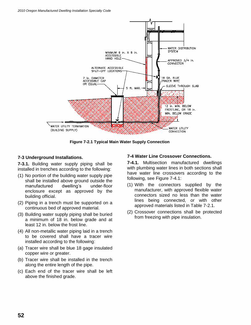
2010 Oregon Manufactured Dwelling Installation Specialty Code
52
Figure 7-2.1 Typical Main Water Supply Connection
7-3 Underground Installations.
7-3.1. Building water supply piping shall be installed in trenches according to the following:
(1) No portion of the building water supply pipe shall be installed above ground outside the manufactured dwelling’s under-floor enclosure except as approved by the building official.
(2) Piping in a trench must be supported on a continuous bed of approved material.
(3) Building water supply piping shall be buried a minimum of 18 in. below grade and at least 12 in. below the frost line.
(4) All non-metallic water piping laid in a trench to be covered shall have a tracer wire installed according to the following:
(a) Tracer wire shall be blue 18 gage insulated copper wire or greater.
(b) Tracer wire shall be installed in the trench along the entire length of the pipe.
(c) Each end of the tracer wire shall be left above the finished grade.
7-4 Water Line Crossover Connections.
7-4.1. Multisection manufactured dwellings with plumbing water lines in both sections shall have water line crossovers according to the following, see Figure 7-4.1:
(1) With the connectors supplied by the manufacturer, with approved flexible water connectors sized no less than the water lines being connected, or with other approved materials listed in Table 7-2.1.
(2) Crossover connections shall be protected from freezing with pipe insulation.

2010 Oregon Manufactured Dwelling Installation Specialty Code
53
Figure 7-4.1 Typical Water Line Crossover Connection
7-4.2 Protection. Exposed sections of water supply piping, shutoff valves, and pressure reducers shall be protected from freezing according to the following:
(1) Wrapped with pipe insulation, or
(2) With the installation of electric heat tape listed and approved for manufactured dwelling use.
7-5 Water Distribution System Testing.
7-5.1 Water Test. Upon completion of the building water supply connection and marriage line crossover connections, the manufactured dwelling water distribution system shall be tested by pressurizing all water lines with water from the site’s water supply or using air at 80 PSI for 15 minutes without loss of pressure or evidence of leakage. When the test is performed using the site’s water supply, the water supply connection, marriage line crossover connections, and fixture connections shall be checked for leaks during the test.
Exception: CPVC piping shall not be tested with air only at 80 PSI. The test pressure may be reduced to 30 PSI when the water system is constructed using CPVC.
7-5.2 Test Failures. Upon failure of the water test in Section 7-5.1, check all applicable field connections, repair any leaks, and repeat the applicable test until the system passes. If tests continue to fail, notify factory authorized service personnel and report failures. The site’s water supply shall remain off, except for further testing, until all leaks have been repaired.
7-6 Drainage System.
7-6.1 Drain Piping. Drain piping under the manufactured dwelling shall be installed according to the manufacturer’s installation instructions and 24 CFR 3280 (MHCSS). The building drain piping shall be new and made of approved materials in accordance with Table 7-6.1 and supported as required in this section.
Table 7-6.1 Approved Drain Piping Materials
Approved Materials Reference Standard
Acrylonite Butadine Styrene (ABS) ASTM D 2661 or ASTM F 628
Polyvinyl Chloride (PVC) ASTM D 2665 or ASTM D 891
NOTES:
(1) See the Oregon Plumbing Specialty Code for a more comprehensive list of approved piping
material.
(2) Piping must be labeled or marked by the manufacturer to indicate that the material conforms to that specific standard.

2010 Oregon Manufactured Dwelling Installation Specialty Code
54
7-6.2 Drain Piping Connection. The installation and connection of the manufactured dwelling drain outlet to the sewer shall comply with this code and where not specific to the Oregon Plumbing Specialty Code. See Figure 7-6.2.
(1) Piping shall be installed to provide a minimum1/4 in. per ft. grade in all horizontal drain piping.
(2) When a cleanout is installed at the upper end of the run, the grade may be reduced to 1/8 in. per ft.
(3) Appropriate sized directional fittings shall be used for all changes in direction.
(4) Piping shall be installed without undue strains, stresses, and shall have provisions for expansion and contraction.
(5) Piping shall be supported at 4 ft. on-center for rigid drain piping (ABS or PVC). Horizontal piping under the home does not require vertical rigid support.
7-6.3 Drain Piping Cleanouts. A cleanout fitting shall be installed in the building drain under or within 5 ft. of the manufactured dwelling. If underground, a two-way cleanout fitting shall be used. The cleanout shall have 18 in. of clearance directly in front of the cleanout opening without removing any permanent construction.
Figure 7-6.2 Typical Drain Line Connection
7-7 Underground Installations.
7-7.1. Building drain piping shall be installed in trenches according to the following:
(1) No portion of the building drain pipe shall be installed above ground outside the manufactured dwelling’s under-floor.
(2) Piping in a trench must be supported on a continuous bed of approved material.
(3) Piping shall be a minimum of 12 in. below grade.
(4) Piping installed deeper than and parallel to footings shall be set away from the footing at a minimum of 45 degrees. See Figure 7-7.1.
(5) All building drain pipe shall be graded at 1/4 in. per foot except as otherwise permitted by the building official.
(6) All non-metallic water piping laid in a trench to be covered shall have a tracer wire installed according to the following:
(e) Tracer wire shall be green 18 gage insulated copper wire or greater.
(f) Tracer wire shall be installed in the trench along the entire length of the pipe.
(g) One end of the tracer wire shall be left above the finished grade at the cleanout next to the manufactured dwelling.

2010 Oregon Manufactured Dwelling Installation Specialty Code
55
Figure 7-7.1 Typical Footing Setback from Trench
7-8 Drain Piping Crossover Connections.
7-8.1. Drainage line crossovers in multisection manufactured dwellings shall be connected in accordance with one of the following, see Figure 7-8.1:
(1) With the materials supplied by the manufacturer and installed according to the manufacturer’s installation instructions.
(2) With approved pipe and fitting connectors of the same diameter as the pipes and fittings being connected and not less than schedule 40 DWV (Drain, Waste, and Vent).
(3) With approved shielded flexible connectors.
Figure 7-8.1 Typical Drain Line Support and Crossover Connection
7-9 Drainage System Testing.
7-9.1 Drainage Test. Upon completion of the building drain connection and marriage line crossover connection, the drainage system shall be rechecked for leaks according to the following:
(1) This test shall be accomplished by testing each fixture or receptor, including the
clothes washer standpipe, by letting water flow through the fixture or receptor at normal operating pressure for a minimum of 3 minutes.
(2) If water under pressure is not available, test each fixture and receptor by pouring at least 3 gallons of water into each fixture and receptor.

2010 Oregon Manufactured Dwelling Installation Specialty Code
56
(3) Visually check the connection on each fixture and receptor during the test to assure there is no evidence of leakage. (Removal of access panels may be required to visually inspect all connections).
7-9.2 Test Failures. Upon failure of any of the above tests, check all applicable field connections, repair any leaks, and repeat the applicable test. If tests continue to fail, notify factory authorized service personnel immediately and report failures. The site’s water supply shall remain off, except for further testing, until all leaks have been repaired.

2010 Oregon Manufactured Dwelling Installation Specialty Code
57
CHAPTER 8
MECHANICAL CONNECTIONS
8-1 General.
8-1.1 Gas Supply. Gas supply requirements not specifically covered in this code shall be in accordance with the Oregon Residential Specialty Code, Chapter 24.
8-2 Gas Supply Crossover Connections.
8-2.1. All gas supply piping crossovers and fittings in multisection manufactured dwellings shall be listed for exterior use and be of the same size as the main unit pipe. Crossover piping shall be made of connectors supplied by the manufacturer or other approved materials.
8-2.3. Tools shall not be used to connect or remove the flexible connector quick-disconnect. If a quick-disconnect is not used, an approved shutoff valve is required at each crossover point upstream of the connection.
8-3 Gas Supply Testing.
8-3.1 Testing. The gas system shall be retested for leaks at the installation site in accordance with the Oregon Residential Specialty Code, Chapter 24.
8-3-2 Connection Procedures. Gas burning–appliance vents shall be inspected to ensure that they have been connected to the appliance and that roof jacks are installed and have not come loose during transit.
8-4 Heating Oil Systems.
8-4.1. Heating oil heating systems shall be installed and tested in accordance with the Oregon Residential Specialty Code, Chapter 22.
8-5 Under-Floor Ducts.
8-5.1 General. Under-floor heat and air conditioning ducts shall be installed with a minimum of bends and excess length so as not to restrict airflow. Ducts shall be supported and connected according to the duct and appliance manufacturer’s instructions. Ducts shall not be crushed, dented, or compressed. All tears, holes, and penetrations shall be sealed with approved foil tape or other approved duct sealer.
8-5.2 Duct Materials. Under-floor heating and air conditioning ducts shall be listed to UL 181.
8-5.2.1. Under-floor duct material shall have a minimum of R-8 insulation, a vapor retarder rated at 1.0 perm or less, an inner liner of spring steel wire helix banded within two layers of 57 gage mylar polyester film or equal, and
an interior diameter not less than the diameter of the plenum collars on the manufactured dwelling.
8-5.2.2 Extensions, Splices, and Sharp Turns. Where extensions, splices or sharp turns (when the inside radius is less than the inside diameter of the duct) are used, they shall be made with minimum 28 gage sheet metal extensions, elbows, tees, wyes, or collars secured with proper mechanical fasteners with each seam and joint sealed with foil tape or other approved duct sealer. The insulation and vapor retarder required above shall be installed on all sheet metal extensions, elbows, tees, wyes, and collars.
8-5.3 Duct Securement. The inner liner shall be secured to the extension, elbow, tee, wye, or collar with proper mechanical fasteners and installed so the insulation and vapor retarder extends up into the floor insulation and bottom board. Ducts shall not have stress at the connection points.
8-5.3.1. The outer liner, insulation, and vapor retarder shall be secured to the extension, elbow or collar with stainless steel worm drive clamps or nylon straps. Stainless steel worm drive clamps, nylon straps, and all duct vapor retarder joints shall be sealed with approved foil tape or other approved duct sealer.
8-5.4 Duct Clearances. Adequate clearances shall be maintained under the manufactured dwelling for the under-floor heat and air conditioning ducts. Ducts shall be elevated above the ground, footing, or slab a minimum of 1 in. with masonry or pressure treated blocks or straps.

2010 Oregon Manufactured Dwelling Installation Specialty Code
58
CHAPTER 9
PREPARATION OF APPLIANCES
9-1 Clothes Dryer Vent.
9-1.1. When a manufactured dwelling is wired for a clothes dryer, the clothes dryer vent shall exhaust to the exterior of the dwelling, beyond any perimeter skirting or foundation installed around it according to the following, and as shown in Figure 9-1.1:
(1) Exhaust ducts shall be installed according to the manufacturer’s installation instructions and this code.
(2) Exhaust ducts shall be a minimum of 4 in. diameter.
(3) Exhaust duct material shall be 30 gage rigid sheet metal, semi-rigid metal, or flexible metal.
(4) Exhaust ducts shall have no dips or traps in the duct run unless a 1/4 in. hole is made at the lowest point of the exhaust duct.
(5) Exhaust ducts shall have no screws, mechanical fasteners, screens or any other obstructions extending into any interior portion of the duct.
(6) Exhaust ducts shall be a maximum of 25 ft. in length. The length shall be reduced by 2-1/2 ft. for each 45-degree bend and 5 ft. for each 90-degree bend.
(7) Exhaust ducts shall be routed through the wall, floor, skirting, foundation, or retaining wall to the exterior of the manufactured dwelling.
(8) Exhaust ducts shall not terminate in any under-floor area, garage, or accessory structure.
(9) The exhaust duct termination shall be equipped with back draft damper.
Figure 9-1.1 Typical Dryer Exhaust Duct Installation

2010 Oregon Manufactured Dwelling Installation Specialty Code
59
9-2 Comfort Heating and Cooling Systems.
9-2.1 Air Conditioners. Installed air-conditioning systems shall not exceed the rating shown on the home's compliance certificate.
9-2.2 Heat Pumps. Heat pumps shall be installed according to the heat pump manufacturer's instructions.
9-2.3 Circuit Rating. If a manufactured dwelling is factory provided with an exterior outlet to energize heating and/or air-conditioning equipment, the branch circuit rating on the tag adjacent to this outlet shall be equal to or greater than the minimum circuit ampacity identified on the equipment rating plate.
9-3 Solid Fuel-Burning Appliances.
9-3.1. Solid fuel-burning appliances, such as fireplaces and wood stoves, may be installed in manufactured dwellings.
9-3.2. Solid fuel-burning appliances shall:
(1) Be listed for use in manufactured dwellings or mobile homes.
(2) Be installed as per 24 CFR 3280 (MHCSS), Section 3280.709, this code, and the manufacturer’s installation instructions.
(3) Be secured to the manufactured dwelling floor.
(4) Not be installed in alcoves or sleeping rooms.
Exception 1: Solid fuel-burning appliances may be installed in alcoves if allowed by the manufacturer’s installation instructions.
Exception 2: Solid fuel-burning appliances may be installed in sleeping areas if approved by HUD as an alternative construction prior to production.
9-3.3. Solid fuel-burning appliance chimneys and air inlets shall be installed in accordance with their listings and Figure 9-3.3.
9-3.4 Minimum Extensions Above Roof. The finished chimney shall extend at least 3 ft. above the highest point at which it penetrates the roof and at least 2 ft. higher than any building or other obstruction located within a horizontal distance of 10 ft. See Figure 9.3.3.
9-3.5 Required Components. The required components of a correctly installed chimney shall be as shown in Figure 9.3.3.
Figure 9-3.3 Typical Fireplace Stove Installation

2010 Oregon Manufactured Dwelling Installation Specialty Code
60
9-4 Combustion Air Duct Inlets.
9-4.1. Combustion air intake ducts shall not terminate under the home and must extend to the home’s exterior outside the skirting.
9-4.2. The air intake ducts shall not be installed in a garage cabana, basement, or other confined area.
9-5 Range, Cooktop, and Oven Venting.
9-5.1. If the home is equipped with a combination range (cooktop/grill) or oven that contains its own exhaust system, the vent shall exhaust to the exterior of the home.
9-5.2. When the vent exhausts through the floor and if perimeter skirting is installed, the vent shall extend through the exterior perimeter of the home.
9-6 Water Heaters.
9-6.1. Water heaters installed in a manufactured dwelling shall be according to this section, and where not specific, to the manufacturer’s installation instructions and the Oregon Residential Specialty Code.
9-6.2. Water heaters installed in a manufactured dwelling during or prior to the initial sale to the first customer shall be installed according to 24 CFR 3280 (MHCSS) and listed for manufactured home or mobile home use.
9-6.3. Water heaters installed in a manufactured dwelling after the completion of the initial sales contract shall be installed according to the following:
(1) Water heaters shall be listed, but do not have to be listed for manufactured home or mobile home use;
(2) Installed according to the appliance manufacturer’s installation instructions; and
(3) If required to have a drain pan installed, the drain pan drain line shall drain to the exterior of the manufactured dwelling. See Figure 9-6.3.
9-6.4. Fuel-burning water heaters shall be installed to provide for the complete separation of the combustion system from the interior atmosphere of the manufactured dwelling by:
(1) The installation of a listed direct vent (sealed combustion system) appliance; or
(2) The installation of the appliance within an enclosure accessible only from outside the manufactured dwelling so as to separate the appliance combustion and venting systems from the interior atmosphere of the manufactured dwelling. There shall not be any door, removable access panel, or other opening into the enclosure from the inside of the manufactured dwelling. Any opening or penetrations for ducts, return air inlets, piping, or wiring shall be sealed with non-combustible caulking or equal.
9-6.5. Fuel-burning water heaters shall be equipped with a direct vent combustion air inlet designed to conduct air directly into the fire chamber. Combustion air shall not be taken from within any manufactured dwelling wall, floor, ceiling, or crawl space.
Figure 9-6.3 Typical Water Heater Drain Pan Drain Line

2010 Oregon Manufactured Dwelling Installation Specialty Code
61
CHAPTER 10
SITE-INSTALLED FEATURES
10-1 General.
10-1.1. All buildings and structures shall be designed to support all of their own live and dead loads and shall comply with the requirements of the State Building Code.
10-1.2. Fire separation distance shall be as per the requirements in Chapter 11.
10-1.3. When the manufacturer's instructions are not available, the blocking, securing, anchoring, and utility connections shall be completed in accordance with the requirements of this code.
10-2 Garages.
10-2.1. Garages shall be constructed to the Oregon Residential Specialty Code and located according to the plans approved by the building official.
(1) Garages may be attached to the manufactured dwelling with flashing, roofing material, or other sealing materials.
(2) Garages may be permanently attached to a manufactured dwelling when a manufactured dwelling is supported and secured to a foundation wall or basement wall according to the requirements of this code.
10-2.2 Access and Egress. Manufactured dwelling access and egress shall be maintained when a garage is attached to a manufactured dwelling.
(1) When a garage encloses a required egress, as required in 24 CFR 3280 (MHCSS), an additional exit door shall be installed in the garage.
(2) At least one required exit door of the manufactured dwelling must open directly to the outside without passing through an accessory building.
10-3 Other Structures.
10-3.1 Porches, Awnings, Carports, Cabanas, Ramadas, Decks, Landings, Stairs, Ramps, Guardrails and Handrails. Site-constructed porches, awnings, carports, cabanas, ramadas, decks, landings, stairs, ramps, guardrails and handrails shall be constructed and inspected according to this code and where not specific, to the Oregon Residential Specialty Code.
10-3.2. Porches, awnings, carports, cabanas, ramadas, decks, landings, stairs, ramps, guardrails and handrails:
(1) Shall be self supported, free standing structures.
(2) May be attached to a manufactured dwelling only with flashing, roofing materials, or other sealing materials to provide a weather seal and prohibit the trapping of water.
(3) When prefabricated, shall be installed according to the structure manufacturer’s installation instructions and this code.
(4) May be supported by the manufactured dwelling when the engineered DAPIA approved plans demonstrate the manufactured dwelling was engineered and constructed to carry the additional live loads, dead loads, and uplift loads imposed by an attached structure.
(5) Prefabricated awnings and carports may be supported by the manufactured dwelling’s exterior wall provided extra perimeter foundation support in that area consisting of one-half spaced perimeter blocking is installed.
(6) Shall not block a required egress as required in 24 CFR 3280 (MHCSS).
Exception: Railings and guardrails may be attached to and supported by the manufactured dwelling.
10-3.3 Dormers and Gables. Roof dormers or gables may be installed over an existing manufactured dwelling roof for the purpose of tying in a garage, cabana, or porch. Dormers and gables shall be installed according to the following:
(1) Constructed according to the Oregon Residential Specialty Code and the roofing manufacturer’s installation instructions; or
(2) Constructed according to the manufacturer’s DAPIA approved plans, and the roofing manufacturer’s installation instructions.
10-3.4 Temporary Steps. Temporary steps are intended for use during the installation of a manufactured dwelling only and are not intended for continuous use by the occupants.
10-3.4.1. Temporary steps shall be removed and replaced with an appropriate permanent structure prior to final inspection.

2010 Oregon Manufactured Dwelling Installation Specialty Code
62
10-3.4.2. Temporary steps shall be provided for at least one door.
10-3.4.3. Temporary steps shall be designed for the applicable loads and constructed according to the following:
(1) A minimum of 36 in. wide, a maximum of 48 in. high, with a maximum 8 in. tread rise, and a minimum of 10 in. tread run. There shall not be more than a 3/8 in. difference in height of any tread rise of the depth of any tread run within the same flight of stairs.
(2) Provided with a handrail on one side 30 in. to 34 in. above the stair tread when there are three or more risers.
(3) Supported in a manner that provides safe, level, and stable stairs.
(4) Provided with a top step not more than 8 in. below the door threshold (no landing is required).
10-3.5 Ramadas. A ramada shall be constructed and installed according to the following:
(1) Designed and constructed to the requirements of this code and, where not specific, to the Oregon Residential Specialty Code.
(2) Shall not be wholly enclosed on the sides or ends.
(3) Shall provide a minimum clearance of not less than:
(a) 18 in. vertically above the highest portion of a manufactured dwelling or cabana roof; and
(b) 6 in. horizontally on either side of a manufactured dwelling or cabana.

2010 Oregon Manufactured Dwelling Installation Specialty Code
63
CHAPTER 11
FIRE AND LIFE SAFETY
11-1 Smoke Alarms.
11-1.1. As required by 24 CFR 3280 (MHCSS) manufacturers shall provide instructions on how to inspect and retest each smoke alarm during initial installation of the home, and provide homeowners with operating and testing information from the smoke alarm manufacturer.
11-1.2. When a manufactured dwelling is relocated, each smoke alarm, as required in ORS 479.260 and OAR 837-045-0050, shall be tested to assure it is connected and in working order.
ORS 479.260 is not part of this code but is
reproduced here for the reader’s convenience:
479.260 Transfer of dwelling unit or lodging house
without smoke alarm or smoke detector
prohibited. (1) A person may not convey fee title to
any real property that includes a dwelling unit or
lodging house, or transfer possession of any dwelling
unit or lodging house pursuant to a land sale contract,
unless there is installed in the dwelling unit or lodging
house a smoke detector or the required number of
approved smoke alarms, installed in accordance with
the state building code and rules of the State Fire
Marshal adopted under ORS 479.295. The smoke
alarms required by this subsection must meet the
requirements of ORS 479.297.
(2)(a) A person may not convey ownership or
transfer possession of any manufactured dwelling, as
defined in ORS 446.003, unless there is installed in
the manufactured dwelling the required number of
approved smoke alarms or smoke detectors, installed
in accordance with the state building code or with the
federal manufactured dwelling construction and safety
standards adopted under ORS 446.155.
(b) A smoke alarm installed in a manufactured
dwelling that is resold by a person other than the
manufacturer or authorized dealer must meet the
requirements of ORS 479.297.
OAR 837-045-0050 is not part of this code but is
reproduced here for the reader’s convenience:
837-045-0050
Installation and Location of Smoke Alarms and
Smoke Detectors (1) All smoke alarms or smoke detectors shall be
installed and located in accordance with the listing
and manufacturer's instructions and OAR 837-045-
0045 through 837-045-0060.
(2) Dwelling Units:
(a) Smoke alarms and smoke detectors in dwelling
units shall be installed in each sleeping room as per
the applicable requirements of the State Building
Code at the time of construction and in the corridor
or area giving access to sleeping areas according to
the manufacturer's instructions. Where sleeping
areas are located on an upper level, the smoke alarm
or smoke detector shall be installed in an accessible
location as close as practical to the center of the
ceiling directly over the stairway. Where sleeping
areas are widely separated (i.e., on different levels
or opposite ends of the dwelling unit) and/or where
a single smoke alarm or smoke detector will not
adequately service all sleeping areas, a smoke alarm
or smoke detector shall be installed adjacent to each
sleeping area.
(b) When activated, the installed smoke alarm(s)
or smoke detector(s) shall produce an alarm sound
audible in the dwelling unit, guestroom(s) and
sleeping area(s).
(3) Efficiency Dwelling Units, Lodging Houses
and Hotels:
(a) In an efficiency dwelling unit, lodging house
guestroom or hotel room or suite, the smoke alarm
or smoke detector shall be installed on the ceiling or
a wall of the main room or sleeping area.
(b) When activated, the smoke alarm(s) or smoke
detector(s) shall produce an alarm sound audible in
the main room and sleeping area(s).
11-2 Fire Separation Distances.
11-2.1. Fire separation distances shall comply with the requirements of this code and where not specific, to the State Building Code.
11-2.2. Fire separation distances outside a manufactured dwelling park shall be in accordance with the Oregon Residential Specialty Code, Section R302, or the requirements of the municipality, whichever is more stringent.
11-2.3. Fire separations within a manufactured dwelling park shall be as required Table 11-2.3, as per ORS 446.100, and where not specific, to the Oregon Residential Specialty Code.
ORS 446.100 is not part of this code but is
reproduced here for the reader’s convenience:
446.100 Prohibited acts in connection with
construction and use of parks; rules for spacing of
units. (1) A person may not:
(a) Construct a mobile home or manufactured
dwelling park at a place that is unsuitable due to
swampy terrain, lack of adequate drainage or
proximity to the breeding places of insects or rodents.
(b) Install a manufactured dwelling closer than five
feet from a property boundary line.
(c) Construct in a mobile home or manufactured
dwelling park a manufactured dwelling space less
than 30 feet in width or less than 40 feet in length.
(2) The Director of the Department of Consumer

2010 Oregon Manufactured Dwelling Installation Specialty Code
64
and Business Services shall adopt rules pursuant to
the rulemaking provisions of ORS chapter 183
specifying minimum distances between adjacent
manufactured dwellings and between manufactured
dwellings and other structures. In adopting these rules,
the director shall take into consideration the standards
established by the National Fire Protection
Association and standards recommended by the State
Fire Marshal.
(3) Except as provided in this subsection, the rules
adopted by the director under subsection (2) of this
section must provide for at least 10 feet of space
between manufactured dwellings. The director may
adopt a rule allowing less than 10 feet of space
between manufactured dwellings that are separated by
a one-hour fire-resistive wall. A standard established
by the director for a one-hour fire-resistive wall
separating manufactured dwellings must be at least as
stringent as the equivalent standard, if any, for a fire-
resistive wall in a two family dwelling under the Low-
Rise Residential Dwelling Code.
11-3 Fire Sprinkler Systems.
11-3.1. Fire sprinkler systems, if provided, shall have a water supply system that complies with NFPA 13D, Standard for the Installation of Sprinkler Systems in One- and Two-Family Dwellings and Manufactured Homes.
11-4 Fire Department Access and Fire Protection Water Supply.
Sections 503 and 508 of the Oregon Fire Code are
not part of this code but are referenced here for
informational purposes only.
The provisions of the Oregon Fire Code, Section 503
Fire Apparatus Access Roads and Section 508 Fire
Protection Water Supplies specify where fire
department access and fire protection water supplies
are required.

2010 Oregon Manufactured Dwelling Installation Specialty Code
65
Table 11-2.3 Minimum Setbacks and Fire Separation Inside Parks
Manufactured Dwellings Accessory Buildings Accessory Structures
Property Line 5 ft. 5 ft. 5 ft.
Park Street 5 ft. 5 ft. 5 ft.
Park Sidewalk 2 ft. 2 ft. 0 ft.
Manufactured Dwelling on Same Lot
See Note (1) & (2) 3 ft. 0 ft.
Manufactured Dwelling on Adjacent Lot
10 ft. 6 ft. 6 ft.
Buildings on the Same Property
10 ft. 6 ft. 6 ft.
Accessory Buildings on Same Lot
3 ft. 3 ft. 0 ft.
Accessory Building on Adjacent Lot
6 ft. 6 ft. 6 ft.
Accessory Structures on Same Lot
0 ft. 0 ft. 0 ft.
Accessory Structures on Adjacent Lot
6 ft. 6 ft. 6 ft.
NOTES:
(1) The building official may approve reduced setbacks and clearances than those dimensions in this table with the use of fire resistive construction according to the prescriptive requirements in the Oregon Residential Specialty Code.
(2) Additional requirements in OAR 918-500-0530 may be applicable.
(3) Setbacks from perimeter property lines and public streets may be greater than those dimensions shown in this table if the municipality adopted local amendments by ordinance.
(4) Setbacks and clearances addressed in this table shall be measured to the exterior wall of the structure and shall not include the eave overhangs except for awnings and carports.

2010 Oregon Manufactured Dwelling Installation Specialty Code
66
APPENDIX A
REFERENCED STANDARDS
A.1-1. The standards or portions thereof listed in this appendix are referenced within this code and shall be considered part of the requirements of this code.
Oregon Residential Specialty Code ................................................................................... 2008 edition
Oregon Structural Specialty Code .............................. 2007 edition – effective 7/1/10 use 2010 edition
Oregon Plumbing Specialty Code ...................................................................................... 2008 edition
Oregon Mechanical Specialty Code ........................... 2007 edition – effective 7/1/10 use 2010 edition
Oregon Electrical Specialty Code ...................................................................................... 2008 edition
Oregon Fire Code ............................................................................................................. 2010 edition
ASCE 7, Minimum Design Loads for Buildings and Other Structures ................................ 2005 edition
ASME A 112.18.6, Flexible Water Connectors .................................................................. 2003 edition
ASTM A 53, Pipe, Steel, Black and Hot-Dipped, Zinc-Coated, Welded, and Seamless ..... 2004 edition
ASTM B 88, Seamless Copper Water Tube ...................................................................... 2003 edition
ASTM C 90, Specification for Load-bearing Concrete Masonry Units ................................ 2003 edition
ASTM D 891, Standard Test Methods for Specific Gravity, Apparent, of Liquid
Industrial Chemicals ................................................................................. 1999 edition
ASTM D 1586, Standard Test Method for Standard Penetration Test (SPT) and
Split-Barrel Sampling of Soils ................................................................... 1999 edition
ASTM D 1587, Acrylonitrile-Butadiene-Styrene (ABS) Plastic Pipe (SDR Series) ............. 1999 edition
ASTM D 1785, Poly (Vinyl Chloride) (PVC) Plastic Pipe, Sch. 40 and 80 .......................... 2006 edition
ASTM D 2241, Poly (Vinyl Chloride) (PVC) Pressure-Rated Pipe (SDR Series) ................ 2006 edition
ASTM D 2239, Polyethylene (PE) Plastic Pipe, (SDR-PR) Based on Controlled
Inside Diameter ........................................................................................ 2003 edition
ASTM D 2282, Acrylonitrile-Butadiene-Styrene (ABS) Plastic Pipe (SDR Series) ............. 1999 edition
ASTM D 2487, Standard Practice for Classification of Soils for Engineering Purposes
(Unified Soil Classification System) .......................................................... 2000 edition
ASTM D 2488, Standard Practice for Description and Identification of Soils
(Visual-Manual Procedure) ....................................................................... 2000 edition
ASTM D 2661, Acrylonitrile-Butadiene-Styrene (ABS) Sch. 40 Plastic Drain, Waste,
and Vent Pipe and Fittings ........................................................................ 2006 edition
ASTM D 2241, Poly (Vinyl Chloride) (PVC) Pressure-Rated Pipe (SDR Series) ................ 2006 edition
ASTM D 2665, Poly (Vinyl Chloride) (PVC) Plastic Drain, Waste, and Vent Pipe
and fittings ................................................................................................ 2004 edition
ASTM F 628, Acrylonitrile-Butadiene-Styrene (ABS) Sch. 40 Plastic Drain, Waste,
and Vent Pipe with a Cellular Core .............................................................. 2006 edition
ASTM F 876, Crosslinked Polyethylene (PEX) Tubing ...................................................... 2005 edition
ASTM F 877, Crosslinked Polyethylene (PEX) Plastic Hot- and Cold-Water
Distribution System ...................................................................................... 2005 edition
AWPA U1, Use Category System: User Specification for Treated Wood ........................... 2004 edition
NFPA 13D, Standard for the Installation of Sprinkler Systems in One- and Two-Family
Dwellings and Manufactured Homes .............................................................. 2007 edition

2010 Oregon Manufactured Dwelling Installation Specialty Code
67
SEI/ASCE, Design and Construction of Frost-Protected Shallow Foundation Systems ..... 2001 edition
Title 24, CFR, Part 3280. Manufactured Home Construction and Safety Standards (MHCSS).
Title 24, CFR, Part 3285. Model Manufactured Home Installation Standards (MMHIS).
UL 181, Factory-made Air Ducts and Air Connectors – with Revisions through May 2003 1996 edition
APPENDIX B
ACRONYMS
B.1.1. This code uses terminology and acronyms unique to the manufactured dwelling and construction industry. The following are explanations of acronyms used in this code and are included here for the convenience of the user.
ABS. Acrylonitrile-Butadiene-Styrene.
ASCE. American Society of Civil Engineers.
AMP. Ampere.
ASME. American Society of Mechanical Engineering.
ASTM. American Society for Testing and Materials.
AWPA. American Wood Protection Association.
BFE. Base Flood Elevation.
CDX. C-D Exposure 1 plywood.
CFM. Cubic feet per minute.
CFR. Code of Federal Regulations.
CMU. Concrete Masonry Unit.
CPVC. Chlorinated Polyvinyl Chloride.
FEMA. Federal Emergency Management Agency.
HUD. U.S. Department of Housing and Urban Development.
LBS. Pounds
NFPA. National Fire Protection Association.
OAR. Oregon Administrative Rule.
ORS. Oregon Revised Statute.
PB. Polybutylene.
PE. Polyethylene
PEX. Crosslinked Polyethylene.
PSI. Pounds per Square Inch.
PSF. Pounds per Square Foot.
PVC. Polyvinyl Chloride.
SEI. Structural Engineering Institute.
UL. Underwriters Laboratories.

Continued 440-2652 (9/07/COM/WEB)
STAFF USE ONLY Code Amendment Proposal Application Application no.:
Approved Denied
Department of Consumer & Business Services Building Codes Division 1535 Edgewater NW, Salem, Oregon Mailing address: P.O. Box 14470, Salem, OR 97309-0404 Phone: (503) 378-4133, Fax: (503) 378-2322 Web: bcd.oregon.gov
Instructions: Fill in all the following information, attach any supplementary information you relied on, and mail to the address listed above. For more information, please refer to the Building Codes Division Web site, bcd.oregon.gov.
APPLICANT INFORMATION Name: Date:
Representing: Phone:
Address (street or P.O. Box): Fax:
City: State: ZIP:
E-mail address: PROPOSED CODE LANGUAGE
This proposed code amendment (check one): Amends (code, edition, section):
Adopts a new section (code, edition):
Repeals (code, edition, section):
You must provide language for review by the division. Failure to provide language will invalidate the application.
Please use the following format to show additions and deletions from the code — strike through deleted text, underline and bold new text.
Use arrow keys to advance to the next text box.
Proposed language:

440-2652 (9/07/COM/WEB)
APPLICATION CRITERIA Attach to this application written responses to the following questions. If needed, include in the response an explanation as to why a question does not apply to your proposed code amendment. The division may reject an incomplete application. Questions:
1. Is your proposed code amendment necessary to correct any unforeseen or probable outcomes resulting from the application of a code section, and if so, why?
2. Is your proposed code amendment needed to protect the health, safety, welfare, comfort, and security of occupants and the public, and if so, why?
3. Does your proposed code amendment correct inadequate application by a code section to a method, material, or design, and if so, how?
4. Is your proposed code amendment necessary to correct unique geographic or climatic conditions within Oregon, and if so, why?
5. Is your proposed code amendment needed to eliminate conflicting, obsolete, or duplicative code provisions or standards among Oregon-adopted codes, statutes, or regulations, and if so, why?
6. Does your proposed code amendment work to conserve scarce resources, and if so, how? 7. Does your proposed code amendment provide for the use of unique or emerging technologies or promote advances
in construction methods, devices, materials, and techniques, and if so, how? 8. Does your proposed code amendment meet any energy conservation or indoor air quality requirements, and if so,
how? 9. Does your proposed code amendment involve the adoption of an electrical or plumbing building product? If an
electrical or plumbing building product is involved, note if the appropriate board approved the product. 10. Does your proposed code amendment create any adverse fiscal impact or cost savings for the general public, the
construction industry, local and state governments, or small businesses? If so, please describe the added or reduced cost of the proposed code amendment, the adverse fiscal impact or cost savings in relation to the current Oregon specialty code, and any standards of measure used to arrive at the result given.
11. If your proposed code amendment relates to the development of a 6,000-square-foot parcel and the construction of a 1,200-square-foot detached single-family dwelling on that parcel, please provide information to assist the division in preparing a housing cost impact statement.
APPLICANT SIGNATURE
Signature: Date: Copyright notice: By signing this proposed code amendment application, I understand and acknowledge that the work contained in this application is original, or if not original, I have the right to copy the work. By signing this work, I understand that any rights I may have in this work, including any form of derivative works and compilations, are assigned to the Department of Consumer and Business Services. I also understand that I do not retain or acquire any rights once this work is used in a Department of Consumer and Business Services publication.
APPLICATION PROCESSING The Building Codes Division screens proposed amendments to determine whether they meet the requirements of Oregon Administrative Rule (OAR) 918-008-0060. The division will return proposed code amendments that do not substantially meet the requirements of OAR 918-008-0060, with specific reasons included in the returned application
If you submit completed proposed code amendments to the division before the end of the timetable established under OAR 918-008-0020, the division will forward them to the appropriate advisory board for review. The division will not forward proposed code amendments that are not completed before the end of the timetable.
If you complete proposed code amendments but do not submit them to the division before the end of the timetable, you may submit them as completed applications for consideration during the next opportunity given to make amendments to the state building code.
Note: The division is not obligated to examine a proposed code amendment submitted after the end of the timetable.


68