oshpd special seismic certification preapproval (osp)...“access to safe, quality healthcare...
TRANSCRIPT

OFFICE OF STATEWIDE HEALTH PLANNING AND DEVELOPMENT FACILITIES DEVELOPMENT DIVISION
“Access to Safe, Quality Healthcare Environments that Meet California’s Diverse and Dynamic Needs”
STATE OF CALIFORNIA – HEALTH AND HUMAN SERVICES AGENCY OSH-FD-759 (REV 12/16/15) Page 1 of 3
APPLICATION FOR OSHPD SPECIAL SEISMIC CERTIFICATION PREAPPROVAL (OSP)
OFFICE USE ONLY
APPLICATION #: OSP – 0075 – 10
OSHPD Special Seismic Certification Preapproval (OSP)
Type: New Renewal
Manufacturer Information
Manufacturer: Nortek Air Solutions
Manufacturer’s Technical Representative: Preston Harris
Mailing Address: 19855 Southwest 124th Avenue, Tualatin, OR 97062
Telephone: (503) 639-0113 Email: [email protected]
Product Information
Product Name: Air Handling Unit and Internal Components
Product Type: Air Handling Unit
Product Model Number: Please refer to attachment for complete list of products tested. (List all unique product identification numbers and/or part numbers)
General Description: Rigid base mounted air handling units without internal or external isolators designed and tested
for the modular configurations shown in the attached drawings. Internal components shall be limited to those listed in the attached product matrices. Seismic enhancements made to the test units and modifications required to address the anomalies observed during the tests shall be incorporated into the production units.
Mounting Description: Rigid Base mounted
Applicant Information
Applicant Company Name: David Evans and Associates, Inc
Contact Person: Alison Wyatt, PE
Mailing Address: 2100 SW River Parkway, Portland, OR 97201
Telephone: (503) 499-0230 Email: [email protected] I hereby agree to reimburse the Office of Statewide Health Planning and Development review fees in accordance with the California Administrative Code, 2016. Signature of Applicant:
Date: 5/25/16 Title: Senior Professional Engineer Company Name: David Evans and Associates, Inc
03/07/2017
OSP-0075-10
Page 1 of 31
OFFICE OF STATEWIDE HEALTH PLANNING AND DEVELOPMENT FACILITIES DEVELOPMENT DIVISION
“Access to Safe, Quality Healthcare Environments that Meet California’s Diverse and Dynamic Needs”
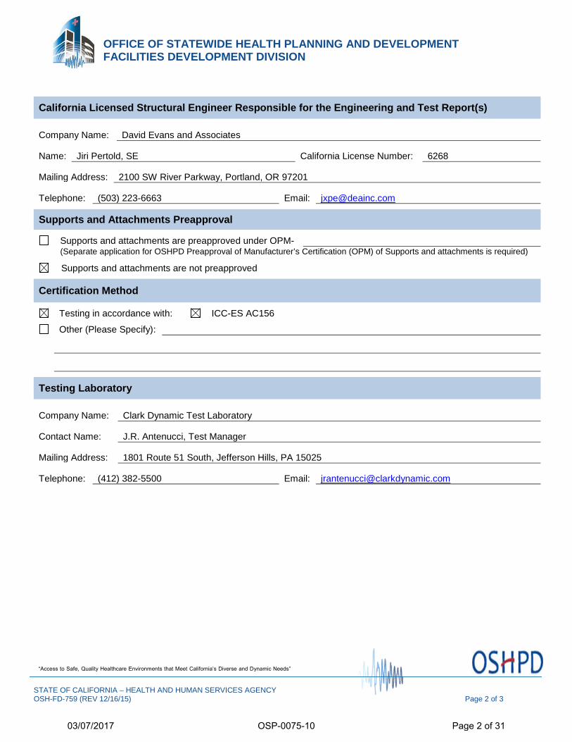
California Licensed Structural Engineer Responsible for the Engineering and Test Report(s)
Company Name: David Evans and Associates
Name: Jiri Pertold, SE California License Number: 6268
Mailing Address: 2100 SW River Parkway, Portland, OR 97201
Telephone: (503) 223-6663 Email: [email protected]
Supports and Attachments Preapproval
Supports and attachments are preapproved under OPM- (Separate application for OSHPD Preapproval of Manufacturer’s Certification (OPM) of Supports and attachments is required)
Supports and attachments are not preapproved
Certification Method
Testing in accordance with: ICC-ES AC156
Other (Please Specify):
Testing Laboratory
Company Name: Clark Dynamic Test Laboratory
Contact Name: J.R. Antenucci, Test Manager
Mailing Address: 1801 Route 51 South, Jefferson Hills, PA 15025
Telephone: (412) 382-5500 Email: [email protected]
STATE OF CALIFORNIA – HEALTH AND HUMAN SERVICES AGENCY OSH-FD-759 (REV 12/16/15) Page 2 of 3
03/07/2017
OSP-0075-10
Page 2 of 31

OFFICE OF STATEWIDE HEALTH PLANNING AND DEVELOPMENT FACILITIES DEVELOPMENT DIVISION
“Access to Safe, Quality Healthcare Environments that Meet California’s Diverse and Dynamic Needs”
STATE OF CALIFORNIA – HEALTH AND HUMAN SERVICES AGENCY OSH-FD-759 (REV 12/16/15) Page 3 of 3
Seismic Parameters
Design in accordance with ASCE 7-10 Chapter 13: Yes No
Design Basis of Equipment or Components (Fp/Wp) = 1.50g
SDS (Design spectral response acceleration at short period, g) = 2.0
ap (In-structure equipment or component amplification factor) = 2.5
Rp (Equipment or component response modification factor) = 6.0
Ω0 (System overstrength factor) = 2.0
Ip (Importance factor) = 1.5
z/h (Height factor ratio) = 1.0
Equipment or Component Natural Frequencies (Hz) = See attachments
Overall dimensions and weight (or range thereof) = See attachments
Equipment or Components @ grade designed in accordance with ASCE 7-10 Chapter 15: Yes No
Design Basis of Equipment or Components (V/W) =
SDS (Design spectral response acceleration at short period, g) =
SD1 (Design spectral response acceleration at 1 second period, g) =
R (Response modification coefficient ) =
Ω0 (System overstrength factor) =
Cd (Deflection amplification factor) =
Ip (Importance factor) = 1.5
Height to Center of Gravity above base =
Equipment or Component Natural Frequencies (Hz) =
Overall dimensions and weight (or range thereof) =
Tank(s) designed in accordance with ASME BPVC, 2015: Yes No
List of Attachments Supporting Special Seismic Certification
Test Report(s) Drawings Calculations Manufacturer’s Catalog
Other(s) (Please Specify): Attachments
OSHPD Approval (For Office Use Only) – Approval Expires on December 31, 2022
Signature: Date: March 7, 2017
Print Name: Timothy J. Piland Title: SSE
Special Seismic Certification Valid Up to : SDS (g) = 2.00 z/h = 1
Condition of Approval (if applicable):
03/07/2017
OSP-0075-10
Page 3 of 31

Tested Enclosure Construction
UUT
Lateral Bracing
Description/ Test
Details Sp
aci
ng
of
late
ral
ele
me
nts
Base
Structure
Material and
Height
Base Material Exterior
Wall
Material
Liner and
Blankoffs
Material
Wall
Thickness
(in)
Doors Mount
Dimensions (in) Max
Operating
Weight
(lb)
Sds
(z/h=
1) Skin Liner Depth Widt
h Height
1a
4 walls 96"
6” Carbon Steel
Structural
Channel
16 ga. G90
Galv Carbon
Steel
Solid 20 ga.
G90 Galv
Carbon
Steel
16 ga. G90
Galv
Carbon
Steel
Solid 20 ga.
G90 Galv
Carbon
Steel
&Stainless
Steel
Standard 2"
Panels
2"
Rigid
Base 96" 96" 96'' 7450 2
1b
2a 4 walls 101"
6” Carbon
Steel Structural
Channel
16 ga. G90
Galv Carbon
Steel
Solid 20 ga.
G90 Galv
Carbon
Steel
16 ga. G90
Galv
Carbon
Steel
Solid 20 ga.
G90 Galv
Carbon
Steel
Standard 4"
Panels 2''
Rigid
Base 108" 144" 144'' 9050 2
2b
Inlet wall removed w/
cable bracing at filter
rack
108.25"
2c
Inlet and outlet walls
removed w/ cable brace
at filter rack and coil
wall. 101"
2d Inlet and outlet walls
removed w/ coil
3a 4 walls
96"
6”
Aluminum
Structural
Tubing
5052
Aluminum,
0.188"
treadplate
Solid 20 ga.
G90 Galv
Carbon
Steel
0.080"
5052
Aluminum
0.063"
5052
Aluminum
Standard 4"
Panels 2''
Rigid
Base 96" 240" 144'' 11600 2
3b
Inlet and outlet walls
removed w/cable brace
on damper wall
Certified Enclosure Modules
Model
Spacing of
lateral
elements
Base
Structure
Base
Ht.
Base Material Exterior
Wall
Material
Liner and
Blankoffs
Material
Wall
Thickness
(in)
Doors Mount
Max Module Dimensions
(in)
Max
Loading
(psf)
Sds
(z/h=
1) Skin Liner Depth Width Height
Enclosure
Modules 96"
Carbon Steel
or
Aluminum,
Channel or
Tube
6”
Galvanized
Steel or
Aluminum
Galvanized
Steel or
Aluminum
Galvanized
Steel or
Aluminum
Galvanized
Steel,
Aluminum, &
Stainless Steel
2" or 4" 2'' or
4''
Rigid
Base
mount
636'' 240" 144" 116 2
Special Seismic Certification Certified Components
Manufacturer: Nortek
Product Line: Custom Air Handling Unit
Certified Options: Direct drive fans, dampers, louvers, fanwalls, coils, VFDs, filters, sound attenuators
Certified Mounting Description: Rigid base mount
03/07/2017
OSP-0075-10
Page 4 of 31
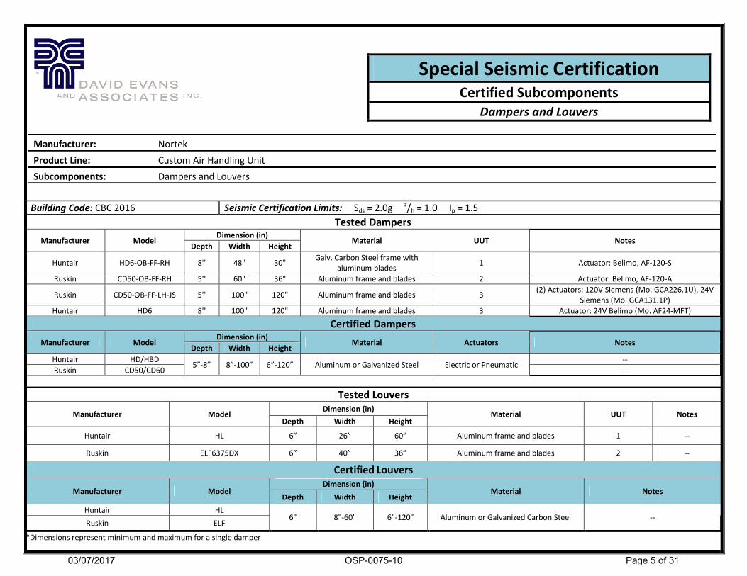
Building Code: CBC 2016 Seismic Certification Limits: Sds = 2.0g z/h = 1.0 Ip = 1.5
Tested Dampers
Manufacturer Model Dimension (in)
Material UUT Notes Depth Width Height
Huntair HD6-OB-FF-RH 8'' 48" 30" Galv. Carbon Steel frame with
aluminum blades 1 Actuator: Belimo, AF-120-S
Ruskin CD50-OB-FF-RH 5'' 60" 36" Aluminum frame and blades 2 Actuator: Belimo, AF-120-A
Ruskin CD50-OB-FF-LH-JS 5'' 100" 120" Aluminum frame and blades 3 (2) Actuators: 120V Siemens (Mo. GCA226.1U), 24V
Siemens (Mo. GCA131.1P)
Huntair HD6 8'' 100" 120" Aluminum frame and blades 3 Actuator: 24V Belimo (Mo. AF24-MFT)
Certified Dampers
Manufacturer Model Dimension (in)
Material Actuators Notes Depth Width Height
Huntair HD/HBD 5”-8” 8”-100” 6”-120” Aluminum or Galvanized Steel Electric or Pneumatic
--
Ruskin CD50/CD60 --
Tested Louvers
Manufacturer Model Dimension (in)
Material UUT Notes Depth Width Height
Huntair HL 6” 26” 60” Aluminum frame and blades 1 --
Ruskin ELF6375DX 6” 40” 36” Aluminum frame and blades 2 --
Certified Louvers
Manufacturer Model Dimension (in)
Material Notes Depth Width Height
Huntair HL 6" 8"-60" 6"-120" Aluminum or Galvanized Carbon Steel --
Ruskin ELF
*Dimensions represent minimum and maximum for a single damper
Special Seismic Certification Certified Subcomponents
Dampers and Louvers
Manufacturer: Nortek
Product Line: Custom Air Handling Unit
Subcomponents: Dampers and Louvers
03/07/2017
OSP-0075-10
Page 5 of 31
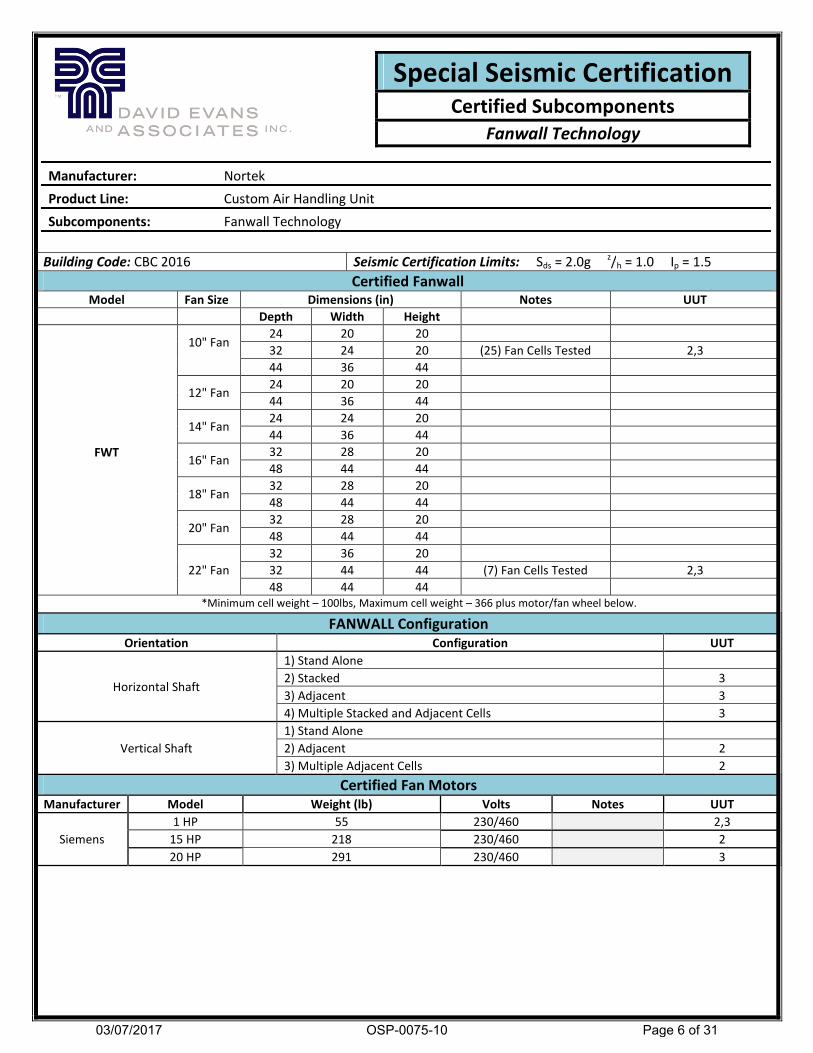
Building Code: CBC 2016 Seismic Certification Limits: Sds = 2.0g z/h = 1.0 Ip = 1.5
Certified Fanwall Model Fan Size Dimensions (in) Notes UUT
Depth Width Height
FWT
10" Fan
24 20 20
32 24 20 (25) Fan Cells Tested 2,3
44 36 44
12" Fan 24 20 20
44 36 44
14" Fan 24 24 20
44 36 44
16" Fan 32 28 20
48 44 44
18" Fan 32 28 20
48 44 44
20" Fan 32 28 20
48 44 44
22" Fan
32 36 20
32 44 44 (7) Fan Cells Tested 2,3
48 44 44
*Minimum cell weight – 100lbs, Maximum cell weight – 366 plus motor/fan wheel below.
FANWALL Configuration
Orientation Configuration UUT
Horizontal Shaft
1) Stand Alone
2) Stacked 3
3) Adjacent 3
4) Multiple Stacked and Adjacent Cells 3
Vertical Shaft
1) Stand Alone
2) Adjacent 2
3) Multiple Adjacent Cells 2
Certified Fan Motors
Manufacturer Model Weight (lb) Volts Notes UUT
Siemens
1 HP 55 230/460 2,3
15 HP 218 230/460 2
20 HP 291 230/460 3
Special Seismic Certification Certified Subcomponents
Fanwall Technology
Manufacturer: Nortek
Product Line: Custom Air Handling Unit
Subcomponents: Fanwall Technology
03/07/2017
OSP-0075-10
Page 6 of 31

Building Code: CBC 2016 Seismic Certification Limits: Sds = 2.0g z/h = 1.0 Ip = 1.5
Tested Coils
Manufacturer Model
Coil
Qty
Coil Face
Height
(in)
Coil
Face
Length
(in)
Row
Qty
Tube
Thickness
(in)
Fins Per
Inch
(FPI)
Fin Material Header Size
(in)
Configuration,
Coil Type Unit
Huntair
5WC-6-85.5x40x1-7 AL 2 85.5 40 1 0.02 7 Aluminum 1.5 Staggered, HW 1
5WC-14-40.5x83x12-6 CU 2 40.5 83 12 0.02 6 Copper 2 Staggered, CW 1
5WC-2-40.5x127x2-14 AL 3 40.5 127 2 0.02 14 Aluminum 1.5 Stand Alone, HW 2
Certified Coils Certified Coil Options
Manufacturer
Coil Face
Height
(in)
Coil Face
Length
(in)
Row
Qty
Tube
Thickness
(in)
Fins Per
Inch
(FPI)
Header Size
(in)
Fin Material
Configuration
Stacked
Model Aluminum Copper
Stand Alone
Huntair WC
Series
Min 6" 12" 1 .020" 5 1-1/4" 0.0075 0.006 Staggered
Max 85.5" 180" 12 .049" 14 4" 0.0095 0.01 Coil Types CW, HW
Certified Non-Active Subcomponents
Component Manufacturer UUT
Sound Attenuator Huntair 2
Humidifier Grids Vapac 1
Filter Rack- Type 8 Huntair 1,3
Filter Frames- HEPA Huntair, AFF, Camfill Farr 2
Filter Frames- Type 8 Holding Huntair 1,3
Special Seismic Certification Certified Subcomponents
Coils & Non-Active Subcomponents
Manufacturer: Nortek
Product Line: Custom Air Handling Unit
Subcomponents: Coils and Additional Non-Active Components
03/07/2017
OSP-0075-10
Page 7 of 31

Building Code: CBC 2016 Seismic Certification Limits: Sds = 2.0g z/h = 1.0 Ip = 1.5
Tested Control and VFD Enclosures
Manufacturer Model Dimension (in)
Material Weight NEMA
Rating UUT
Depth Width Height
Enclosures
12” 36” 48”
Aluminum
500 lbs NEMA 3R 1b
Huntair 16” 28” 42” 450 lbs NEMA 12 2a
20” 56” 72'' 1000 lbs NEMA 1 1a
*letters a and b represent separate panels on one unit
Certified Control and VFD Enclosures
Manufacturer Model Dimension (in)
Material NEMA Rating Weight Depth Width Height
Huntair Enclosures 12''-20'' 20''-56'' 24''-72'' Aluminum NEMA 1, 3R, 4
and 12
450 lbs-
1000 lbs
*height and width range from minimum to maximum in 1'' increments
Building Code: CBC 2016 Seismic Certification Limits: Sds = 2.0g z/h = 1.0 Ip = 1.5
Tested Power Distribution and MSP Enclosures
Manufacturer Model Dimension (in)
Material Weight NEMA
Rating UUT
Depth Width Height
Huntair Enclosures 10'' 16'' 16''
Aluminum 30 lbs NEMA 4 2b
6'' 24'' 24'' 50 lbs NEMA 3R 3
*letters a and b represent separate panels on one unit
Certified Power Distribution and MSP Enclosures
Manufacturer Model Dimension (in)
Material NEMA Rating Weight Depth Width Height
Huntair Enclosures 6''-10'' 6''-24'' 8''-24'' Aluminum NEMA 1, 3R, 4
and 12 5 lbs-50 lbs
*height and width range from minimum to maximum in 1'' increments
Special Seismic Certification Certified Subcomponents
Subcomponent Enclosures
Manufacturer: Nortek
Product Line: Custom Air Handling Unit
Subcomponents: Control, VFD, Power Distribution and MSP Enclosures
03/07/2017
OSP-0075-10
Page 8 of 31
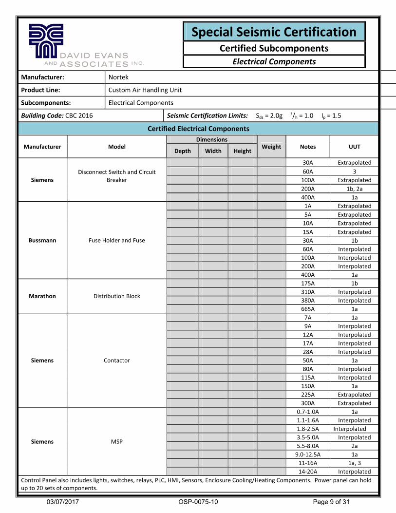
Manufacturer: Nortek
Product Line: Custom Air Handling Unit
Subcomponents: Electrical Components
Building Code: CBC 2016 Seismic Certification Limits: Sds = 2.0g z/h = 1.0 Ip = 1.5
Certified Electrical Components
Manufacturer Model Dimensions
Weight Notes UUT Depth Width Height
Siemens
Disconnect Switch and Circuit
Breaker
30A Extrapolated
60A 3
100A Extrapolated
200A 1b, 2a
400A 1a
Bussmann Fuse Holder and Fuse
1A Extrapolated
5A Extrapolated
10A Extrapolated
15A Extrapolated
30A 1b
60A Interpolated
100A Interpolated
200A Interpolated
400A 1a
Marathon Distribution Block
175A 1b
310A Interpolated
380A Interpolated
665A 1a
Siemens Contactor
7A 1a
9A Interpolated
12A Interpolated
17A Interpolated
28A Interpolated
50A 1a
80A Interpolated
115A Interpolated
150A 1a
225A Extrapolated
300A Extrapolated
Siemens MSP
0.7-1.0A 1a
1.1-1.6A Interpolated
1.8-2.5A Interpolated
3.5-5.0A Interpolated
5.5-8.0A 2a
9.0-12.5A 1a
11-16A 1a, 3
14-20A Interpolated
Control Panel also includes lights, switches, relays, PLC, HMI, Sensors, Enclosure Cooling/Heating Components. Power panel can hold
up to 20 sets of components.
Special Seismic Certification Certified Subcomponents
Electrical Components
03/07/2017
OSP-0075-10
Page 9 of 31
Manufacturer: Nortek
Product Line: Custom Air Handling Unit
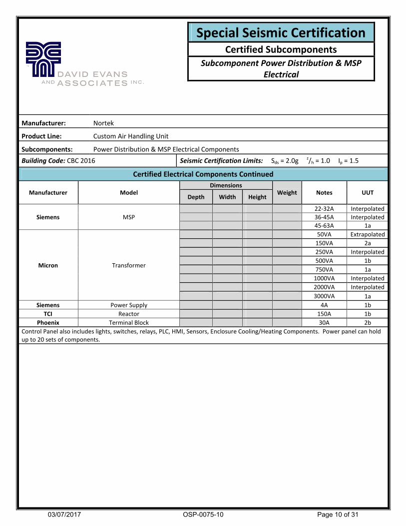
Subcomponents: Power Distribution & MSP Electrical Components
Building Code: CBC 2016 Seismic Certification Limits: Sds = 2.0g z/h = 1.0 Ip = 1.5
Certified Electrical Components Continued
Manufacturer Model Dimensions
Weight Notes UUT Depth Width Height
Siemens MSP
22-32A Interpolated
36-45A Interpolated
45-63A 1a
Micron Transformer
50VA Extrapolated
150VA 2a
250VA Interpolated
500VA 1b
750VA 1a
1000VA Interpolated
2000VA Interpolated
3000VA 1a
Siemens Power Supply 4A 1b
TCI Reactor 150A 1b
Phoenix Terminal Block 30A 2b
Control Panel also includes lights, switches, relays, PLC, HMI, Sensors, Enclosure Cooling/Heating Components. Power panel can hold
up to 20 sets of components.
Special Seismic Certification Certified Subcomponents
Subcomponent Power Distribution & MSP
Electrical
03/07/2017
OSP-0075-10
Page 10 of 31

Building Code: CBC 2016 Seismic Certification Limits: Sds = 2.0g z/h = 1.0 Ip = 1.5
Certified Variable Frequency Drives
Manufacturer Model VFD Size
(HP)
Dimensions (in) Weight (lbs) UUT
Depth Width Height
ABB
ACH550 Series
1
18 1a
3
18 Interpolated
5
18 Interpolated
7.5
18 Interpolated
10 25 Interpolated
15 25 Interpolated
20 41 Interpolated
25 41 Interpolated
30 41 Interpolated
35 58 Interpolated
40 58 Interpolated
50 58 Interpolated
60 58 Interpolated
75 58 Interpolated
100 190 Interpolated
125 190 Interpolated
150 190 1a
ACH320 Series
1 3.5 1b
3 3.5 Interpolated
5 3.5 Interpolated
7.5 7 Interpolated
10 7 Interpolated
15 7 Interpolated
20 11 1b
25 11 Extrapolated
30 11 Extrapolated
Danfoss VLT Series 150 212 2a
Special Seismic Certification Certified Subcomponents
Subcomponent Variable Frequency Drives
Manufacturer: Nortek
Product Line: Custom Air Handling Unit
Subcomponents: Variable Frequency Drives
03/07/2017
OSP-0075-10
Page 11 of 31
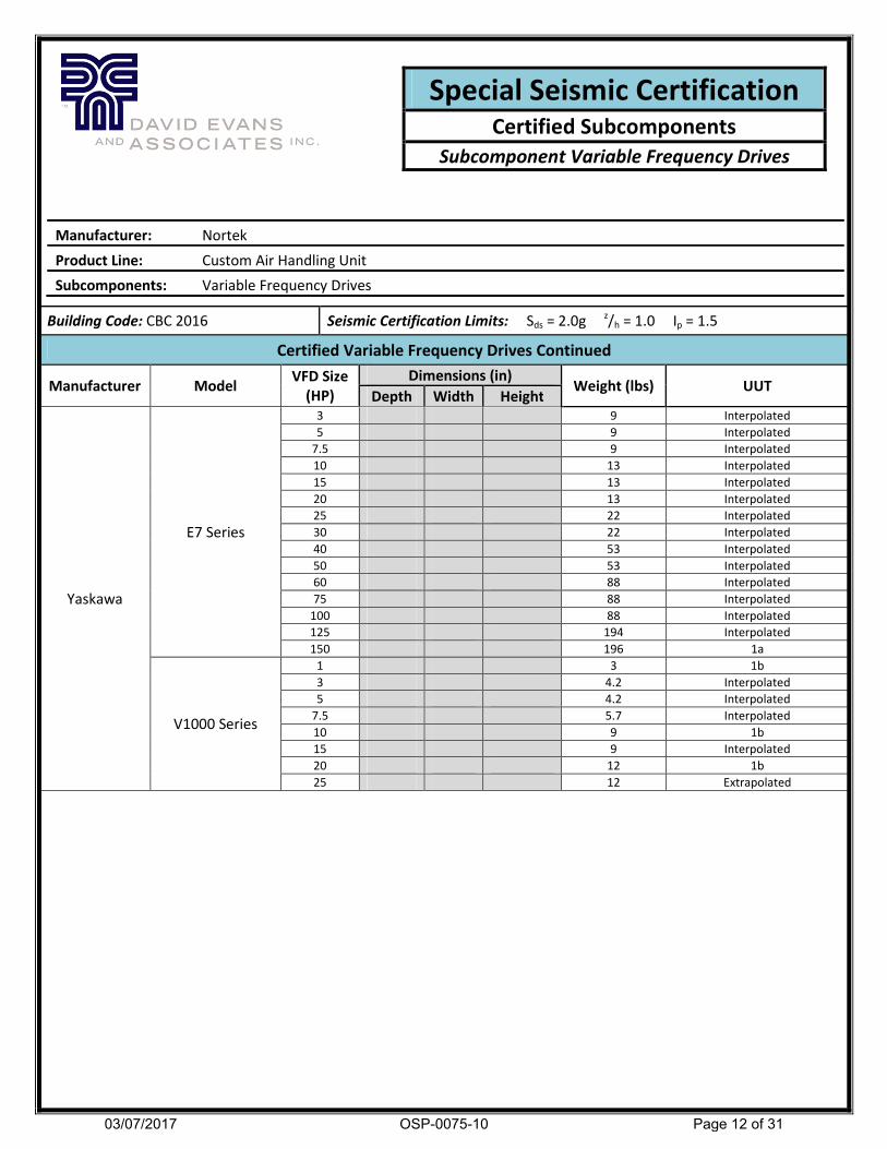
Building Code: CBC 2016 Seismic Certification Limits: Sds = 2.0g z/h = 1.0 Ip = 1.5
Certified Variable Frequency Drives Continued
Manufacturer Model VFD Size
(HP)
Dimensions (in) Weight (lbs) UUT
Depth Width Height
Yaskawa
E7 Series
3 9 Interpolated
5 9 Interpolated
7.5 9 Interpolated
10 13 Interpolated
15 13 Interpolated
20 13 Interpolated
25 22 Interpolated
30 22 Interpolated
40 53 Interpolated
50 53 Interpolated
60 88 Interpolated
75 88 Interpolated
100 88 Interpolated
125 194 Interpolated
150 196 1a
V1000 Series
1 3 1b
3 4.2 Interpolated
5 4.2 Interpolated
7.5 5.7 Interpolated
10 9 1b
15 9 Interpolated
20 12 1b
25 12 Extrapolated
Special Seismic Certification Certified Subcomponents
Subcomponent Variable Frequency Drives
Manufacturer: Nortek
Product Line: Custom Air Handling Unit
Subcomponents: Variable Frequency Drives
03/07/2017
OSP-0075-10
Page 12 of 31

Manufacturer: Nortek
Product Line: Custom Air Handling Unit
Subcomponents: Additional Subcomponents
Building Code: CBC 2016 Seismic Certification Limits: Sds = 2.0g z/h = 1.0 Ip = 1.5
Certified Additional Components
Manufacturer
Model Dimension (in)
Weight UUT Depth Width Height
Pfannenberg Thermostat All
Dwyer Transducer/Display 1b
Siemens
PLC Controls
Circuit Breaker 1b
Siemens Power Supply 1b
Siemens Controller 1b
Siemens Analog in/out Module 1b
Siemens Modbus Module 1b
Siemens Ethernet Module 1b
Siemens Touch Screen (4'' min
to 19'' max)
1b
U.S. Toyo Cool Fan (4'' min to 6'' max) 120-240 V all
Special Seismic Certification Certified Subcomponents
Additional Subcomponents
03/07/2017
OSP-0075-10
Page 13 of 31
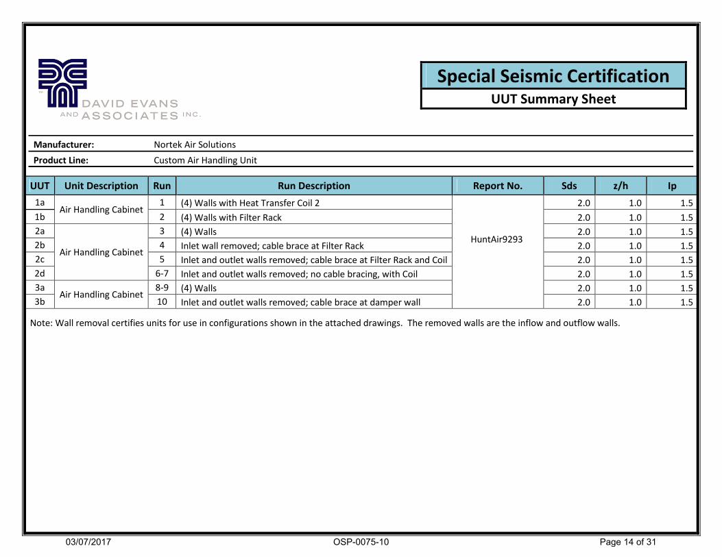
UUT Unit Description Run Run Description Report No. Sds z/h Ip
1a Air Handling Cabinet
1 (4) Walls with Heat Transfer Coil 2
HuntAir9293
2.0 1.0 1.5
1b 2 (4) Walls with Filter Rack 2.0 1.0 1.5
2a
Air Handling Cabinet
3 (4) Walls 2.0 1.0 1.5
2b 4 Inlet wall removed; cable brace at Filter Rack 2.0 1.0 1.5
2c 5 Inlet and outlet walls removed; cable brace at Filter Rack and Coil 2.0 1.0 1.5
2d 6-7 Inlet and outlet walls removed; no cable bracing, with Coil 2.0 1.0 1.5
3a Air Handling Cabinet
8-9 (4) Walls 2.0 1.0 1.5
3b 10 Inlet and outlet walls removed; cable brace at damper wall 2.0 1.0 1.5
Note: Wall removal certifies units for use in configurations shown in the attached drawings. The removed walls are the inflow and outflow walls.
Special Seismic Certification UUT Summary Sheet
Manufacturer: Nortek Air Solutions
Product Line: Custom Air Handling Unit
03/07/2017
OSP-0075-10
Page 14 of 31

Manufacturer: Nortek
Product Line: Custom Air Handling Unit
Serial Number: N/A
Product Construction Summary:
Panel: Standard 2" panels in 16 ga. G90 galvanized steel with Stainless Steel liner and blankoffs in Coil Section and 20 ga
G90 galvanized steel liner and blankoffs everywhere else.
Base: Carbon Steel Structural Channel Base frame with 16 ga. G90 galvanized steel skin and 20 ga G90 galvanized steel base
liner.
Doors: (2) Doors 2" thick; 18.5(W) x 61.5(H) with thermal break window, 12.5(W)x61.5(H) no window.
Openings: (2) Openings; Huntair OSA Damper, 48(W) x 30(H), Belimo 120V Actuator; Huntair OSA Louver, 26(W)x60(H)
Subcomponent/Options Summary:
Heat Transfer Coil: Qty. (2)- (HT1) Huntair, 7 FPI, 1 row, aluminum, staggered mounting; Qty. (2) - Huntair, FPI, 12
rows, copper, staggered mounting
Filter Rack: Type 8, 4" pre-filter, 12" final filter
Humidifier: Vapac
Electrical Control Panels: Qty. (1) - NEMA1 (1a), VFD 1: ABB ACH550 150 HP, VFD 2: Yaskawa E7 150 HP;
Qty. (1) NEMA 3R (1b), PLC, Yaskawa V1000 1, 10, 20 HP VFD's, ABB ACH320 1, 20 HP VFD's
Configuration: (4) walls in place with Heat Transfer Coil 2
Run Operating Weight
(lb)
Dimensions (in.) Lowest Natural Frequency (Hz)
Depth Width Height Front-Back Side-Side Vertical
1 7,450 96.25 96 96 15.2 10.7 20.5
Building Code Test Criteria Sds (g) z/h Ip Aflx-H
(g)
Arig-H
(g)
Aflx-v
(g) Arig-V (g)
CBC 2016 2015 ICC-ES
AC156 2.0 1.0 1.5 3.2 2.4 1.33 0.53
Testing Results: The UUT was full of content and was functional before and after shake table testing. The
structural integrity of the component and attachment system and force-resisting systems was maintained.
Unit Mounting Description: All test units contain an integrated structural base frame. This unit was mounted
directly to the seismic table using twelve (12) ½”-13 Grade 5 hex head bolts (3 bolts on every side) with flat washers
and lock washers.
UUT 1a UNIT UNDER TEST (UUT)
Summary Sheet
03/07/2017
OSP-0075-10
Page 15 of 31

Manufacturer: Nortek
Product Line: Custom Air Handling Unit
Serial Number: N/A
Product Construction Summary:
Panel: Standard 2" panels in 16 ga. G90 galvanized steel with Stainless Steel liner and blankoffs in Coil Section and 20 ga
G90 galvanized steel liner and blankoffs everywhere else.
Base: Carbon Steel Structural Channel Base frame with 16 ga. G90 galvanized steel skin and 20 ga G90 galvanized steel base
liner.
Doors: (2) Doors 2" thick; 18.5(W) x 61.5(H) with thermal break window, 12.5(W)x61.5(H) no window.
Openings: (2) Openings; Huntair OSA Damper, 48(W) x 30(H), Belimo 120V Actuator; Huntair OSA Louver, 26(W)x60(H)
Subcomponent/Options Summary:
Heat Transfer Coil: Qty. (2)- (HT1) Huntair, 7 FPI, 1 row, aluminum, staggered mounting; Qty. (2) - Huntair, FPI, 12
rows, copper, staggered mounting
Filter Rack: Type 8, 4" pre-filter, 12" final filter
Humidifier: Vapac
Electrical Control Panels: Qty. (1) - NEMA1 (1a), VFD 1: ABB ACH550 150 HP, VFD 2: Yaskawa E7 150 HP;
Qty. (1) NEMA 3R (1b), PLC, Yaskawa V1000 1, 10, 20 HP VFD's, ABB ACH320 1, 20 HP VFD's
Configuration: (4) walls in place with Filter Rack
Run Operating Weight
(lb)
Dimensions (in.) Lowest Natural Frequency (Hz)
Depth Width Height Front-Back Side-Side Vertical
1 7,450 96.25 96 96 15.2 10.7 20.5
Building Code Test Criteria Sds (g) z/h Ip Aflx-H
(g)
Arig-H
(g)
Aflx-v
(g) Arig-V (g)
CBC 2016 2015 ICC-ES
AC156 2.0 1.0 1.5 3.2 2.4 1.33 0.53
Testing Results: The UUT was full of content and was functional before and after shake table testing. The
structural integrity of the component and attachment system and force-resisting systems was maintained.
Unit Mounting Description: All test units contain an integrated structural base frame. This unit was mounted
directly to the seismic table using twelve (12) ½”-13 Grade 5 hex head bolts (3 bolts on every side) with flat washers
and lock washers.
UUT 1b UNIT UNDER TEST (UUT)
Summary Sheet
03/07/2017
OSP-0075-10
Page 16 of 31

Subcomponent/Options Summary:
Manufacturer: Nortek
Product Line: Custom Air Handling Unit
Serial Number: N/A
Product Construction Summary:
Panel: Standard 4" panels in 16 ga. G90 galvanized steel and 20 ga G90 galvanized steel liner and blankoffs.
Base: Carbon Steel Structural Channel Base frame with 16 ga. G90 galvanized steel skin and 20 ga G90 galvanized
steel base liner
Doors: (2) Doors 2" thick; 18.5(W) x 61.5(H) with thermal break window, 30.5(W)x24.5(H) no window
Openings: (2) Openings; Ruskin (Return Air) Damper, 60(W) x 36(H), Belimo Actuator; Ruskin (Exhaust) Louver,
40(W)x36(H)
FANWALL: Qty. (1) - (3) fans, vertical upflow (2 up, 1 down), 10" and 22" wheels, welded cells, 1 HP and 15 HP motor
Heat Transfer Coil: Qty. (3)- (HT3) Huntair, 14 FPI, 2 row, aluminum, stand alone configuration
Filter Rack: HEPA Filters
MSP Enclosure: (NEMA 4) (2b)
Electrical Control Panels: Qty. (1) - NEMA12 (2a), VFD: Danfoss VLT 100 HP, Recessed panel construction
Configuration: (4) walls in place
Run Operating Weight
(lb)
Dimensions (in.) Lowest Natural Frequency (Hz)
Depth Width Height Front-Back Side-Side Vertical
3 9,050 108.25 144 144.25 4 6.6 20.6
Building Code Test Criteria Sds (g) z/h Ip Aflx-H (g) Arig-H (g) Aflx-v (g) Arig-V (g)
CBC 2016 2015 ICC-ES
AC156 2.0 1.0 1.5 3.2 2.4 1.33 0.53
Testing Results: The UUT was full of content and was functional before and after shake table testing. The
structural integrity of the component and attachment system and force-resisting systems was maintained.
Unit Mounting Description: All test units contain an integrated structural base frame. This unit was mounted
directly to the table using fourteen (14) ½” – 13 Grade 5 hex head bolts (7 bolts on both exterior sides) with flat
washer and lock washers.
UUT 2a UNIT UNDER TEST (UUT)
Summary Sheet
03/07/2017
OSP-0075-10
Page 17 of 31

Subcomponent/Options Summary:
Manufacturer: Nortek
Product Line: Custom Air Handling Unit
Serial Number: N/A
Product Construction Summary:
Panel: Standard 4" panels in 16 ga. G90 galvanized steel and 20 ga G90 galvanized steel liner and blankoffs.
Base: Carbon Steel Structural Channel Base frame with 16 ga. G90 galvanized steel skin and 20 ga G90 galvanized
steel base liner
Doors: (2) Doors 2" thick; 18.5(W) x 61.5(H) with thermal break window, 30.5(W)x24.5(H) no window
Openings: (2) Openings; Ruskin (Return Air) Damper, 60(W) x 36(H), Belimo Actuator; Ruskin (Exhaust) Louver,
40(W)x36(H)
FANWALL: Qty. (1) - (3) fans, vertical upflow (2 up, 1 down), 10" and 22" wheels, welded cells, 1 HP and 15 HP motor
Heat Transfer Coil: Qty. (3)- (HT3) Huntair, 14 FPI, 2 row, aluminum, stand alone configuration
Filter Rack: HEPA Filters
MSP Enclosure: (NEMA 4) (2b)
Electrical Control Panels: Qty. (1) - NEMA12 (2a), VFD: Danfoss VLT 100 HP, Recessed panel construction
Configuration: Inlet wall removed; cable bracing at the filter rack
Run Operating Weight
(lb)
Dimensions (in.) Lowest Natural Frequency (Hz)
Depth Width Height Front-Back Side-Side Vertical
4 9,050 108.25 144 144.25 4 6.6 20.6
Building Code Test Criteria Sds (g) z/h Ip Aflx-H (g) Arig-H (g) Aflx-v (g) Arig-V (g)
CBC 2016 2015 ICC-ES
AC156 2.0 1.0 1.5 3.2 2.4 1.33 0.53
Testing Results: The UUT was full of content and was functional before and after shake table testing. The
structural integrity of the component and attachment system and force-resisting systems was maintained.
Unit Mounting Description: All test units contain an integrated structural base frame. This unit was mounted
directly to the table using fourteen (14) ½” – 13 Grade 5 hex head bolts (7 bolts on both exterior sides) with flat
washer and lock washers.
UUT 2b UNIT UNDER TEST (UUT)
Summary Sheet
03/07/2017
OSP-0075-10
Page 18 of 31

Subcomponent/Options Summary:
Manufacturer: Nortek
Product Line: Custom Air Handling Unit
Serial Number: N/A
Product Construction Summary:
Panel: Standard 4" panels in 16 ga. G90 galvanized steel and 20 ga G90 galvanized steel liner and blankoffs.
Base: Carbon Steel Structural Channel Base frame with 16 ga. G90 galvanized steel skin and 20 ga G90 galvanized
steel base liner
Doors: (2) Doors 2" thick; 18.5(W) x 61.5(H) with thermal break window, 30.5(W)x24.5(H) no window
Openings: (2) Openings; Ruskin (Return Air) Damper, 60(W) x 36(H), Belimo Actuator; Ruskin (Exhaust) Louver,
40(W)x36(H)
FANWALL: Qty. (1) - (3) fans, vertical upflow (2 up, 1 down), 10" and 22" wheels, welded cells, 1 HP and 15 HP motor
Heat Transfer Coil: Qty. (3)- (HT3) Huntair, 14 FPI, 2 row, aluminum, stand alone configuration
Filter Rack: HEPA Filters
MSP Enclosure: (NEMA 4) (2b)
Electrical Control Panels: Qty. (1) - NEMA12 (2a), VFD: Danfoss VLT 100 HP, Recessed panel construction
Configuration: Inlet and outlet walls removed; cable bracing at filter rack and coil
Run Operating Weight
(lb)
Dimensions (in.) Lowest Natural Frequency (Hz)
Depth Width Height Front-Back Side-Side Vertical
5 9,050 108.25 144 144.25 4 6.6 20.6
Building Code Test Criteria Sds (g) z/h Ip Aflx-H (g) Arig-H (g) Aflx-v (g) Arig-V (g)
CBC 2016 2015 ICC-ES
AC156 2.0 1.0 1.5 3.2 2.4 1.33 0.53
Testing Results: The UUT was full of content and was functional before and after shake table testing. The
structural integrity of the component and attachment system and force-resisting systems was maintained.
Unit Mounting Description: All test units contain an integrated structural base frame. This unit was mounted
directly to the table using fourteen (14) ½” – 13 Grade 5 hex head bolts (7 bolts on both exterior sides) with flat
washer and lock washers.
UUT 2c UNIT UNDER TEST (UUT)
Summary Sheet
03/07/2017
OSP-0075-10
Page 19 of 31

Subcomponent/Options Summary:
Manufacturer: Nortek
Product Line: Custom Air Handling Unit
Serial Number: N/A
Product Construction Summary:
Panel: Standard 4" panels in 16 ga. G90 galvanized steel and 20 ga G90 galvanized steel liner and blankoffs.
Base: Carbon Steel Structural Channel Base frame with 16 ga. G90 galvanized steel skin and 20 ga G90 galvanized
steel base liner
Doors: (2) Doors 2" thick; 18.5(W) x 61.5(H) with thermal break window, 30.5(W)x24.5(H) no window
Openings: (2) Openings; Ruskin (Return Air) Damper, 60(W) x 36(H), Belimo Actuator; Ruskin (Exhaust) Louver,
40(W)x36(H)
FANWALL: Qty. (1) - (3) fans, vertical upflow (2 up, 1 down), 10" and 22" wheels, welded cells, 1 HP and 15 HP motor
Heat Transfer Coil: Qty. (3)- (HT3) Huntair, 14 FPI, 2 row, aluminum, stand alone configuration
Filter Rack: HEPA Filters
MSP Enclosure: (NEMA 4) (2b)
Electrical Control Panels: Qty. (1) - NEMA12 (2a), VFD: Danfoss VLT 100 HP, Recessed panel construction
Configuration: Inlet and outlet walls removed; no cable bracing
Run Operating Weight
(lb)
Dimensions (in.) Lowest Natural Frequency (Hz)
Depth Width Height Front-Back Side-Side Vertical
6-7 9,050 108.25 144 144.25 4 6.6 20.6
Building Code Test Criteria Sds (g) z/h Ip Aflx-H (g) Arig-H (g) Aflx-v (g) Arig-V (g)
CBC 2016 2015 ICC-ES
AC156 2.0 1.0 1.5 3.2 2.4 1.33 0.53
Testing Results: The UUT was full of content and was functional before and after shake table testing. The
structural integrity of the component and attachment system and force-resisting systems was maintained.
Unit Mounting Description: All test units contain an integrated structural base frame. This unit was mounted
directly to the table using fourteen (14) ½” – 13 Grade 5 hex head bolts (7 bolts on both exterior sides) with flat
washer and lock washers.
UUT 2d UNIT UNDER TEST (UUT)
Summary Sheet
03/07/2017
OSP-0075-10
Page 20 of 31

Subcomponent/Options Summary:
Manufacturer: Nortek
Product Line: Custom Air Handling Unit
Serial Number: N/A
Product Construction Summary:
Panel: Standard 4" panels in 0.080" thick, 5052 aluminum and 0.063" thick, 5052 aluminum liner and blankoffs
everywhere else.
Base: Aluminum Structural Tubing Base frame with 5052 Aluminum skin, 0.188" thick treadplate, and 20 ga G90
galvanized steel base liner
Doors: (1) Door 2" thick; 12.5(W) x 61.5(H) no window
Openings: (2) Openings; Ruskin Damper (Supply Air), 100(W) x 120(H), Seimens Actuators (Qty 2 -120V, 24V); Huntair
Damper(Supply Air), 100(W)x120(H), 24V Belimo Actuator
Fanwall: 29 fans, 10" and 22" wheels; horizontal standard, 5 cell(W) x 7 cell(H); welded and riveted cells, Back draft
Dampers, 1 HP and 20 HP motors
Filter Rack: Type 8, 4" pre-filter, 12" final filter
Hoffman Enclosure: (NEMA 1) Terminal Blocks
Damper
Configuration: 4 walls in place
Run Operating Weight
(lb)
Dimensions (in.) Lowest Natural Frequency (Hz)
Depth Width Height Front-Back Side-Side Vertical
9 11,600 96.25 240 144.5 4.7 3.9 14.1
Building Code Test Criteria Sds (g) z/h Ip Aflx-H (g) Arig-H (g) Aflx-v (g) Arig-V (g)
CBC 2016 2015 ICC-ES
AC156 2.0 1.0 1.5 3.2 2.4 1.33 0.53
Testing Results: The UUT contained was full of content and was functional before and after shake table testing. The
structural integrity of the component and attachment system and force-resisting systems was maintained.
Unit Mounting Description: All test units contain an integrated structural base frame. This unit was mounted directly to
the seismic table using sixteen (16) ½” – 13 Grade 5 hex head bolts (8 bolts per both exterior sides) with flat washers
and lock washers.
UUT 3a UNIT UNDER TEST (UUT)
Summary Sheet
03/07/2017
OSP-0075-10
Page 21 of 31

Subcomponent/Options Summary:
Manufacturer: Nortek
Product Line: Custom Air Handling Unit
Serial Number: N/A
Product Construction Summary:
Panel: Standard 4" panels in 0.080" thick, 5052 aluminum and 0.063" thick, 5052 aluminum liner and blankoffs
everywhere else.
Base: Aluminum Structural Tubing Base frame with 5052 Aluminum skin, 0.188" thick treadplate, and 20 ga G90
galvanized steel base liner
Doors: (1) Door 2" thick; 12.5(W) x 61.5(H) no window
Openings: (2) Openings; Ruskin Damper (Supply Air), 100(W) x 120(H), Seimens Actuators (Qty 2 -120V, 24V); Huntair
Damper(Supply Air), 100(W)x120(H), 24V Belimo Actuator
Fanwall: 29 fans, 10" and 22" wheels; horizontal standard, 5 cell(W) x 7 cell(H); welded and riveted cells, Back draft
Dampers, 1 HP and 20 HP motors
Filter Rack: Type 8, 4" pre-filter, 12" final filter
Hoffman Enclosure: (NEMA 1) Terminal Blocks
Damper
Configuration: Inlet and outlet walls removed; cable bracing on damper wall only
Run Operating Weight
(lb)
Dimensions (in.) Lowest Natural Frequency (Hz)
Depth Width Height Front-Back Side-Side Vertical
9 11,600 96.25 240 144.5 4.7 3.9 14.1
Building Code Test Criteria Sds (g) z/h Ip Aflx-H (g) Arig-H (g) Aflx-v (g) Arig-V (g)
CBC 2016 2015 ICC-ES
AC156 2.0 1.0 1.5 3.2 2.4 1.33 0.53
Testing Results: The UUT contained was full of content and was functional before and after shake table testing. The
structural integrity of the component and attachment system and force-resisting systems was maintained.
Unit Mounting Description: All test units contain an integrated structural base frame. This unit was mounted
directly to the seismic table using sixteen (16) ½” – 13 Grade 5 hex head bolts (8 bolts per both exterior sides) with
flat washers and lock washers.
UUT 3b UNIT UNDER TEST (UUT)
Summary Sheet
03/07/2017
OSP-0075-10
Page 22 of 31

6" height max
03/07/2017
OSP-0075-10
Page 23 of 31

6" height max
03/07/2017
OSP-0075-10
Page 24 of 31

1. All dimensions are in inches unless stated otherwise.
6" height max
03/07/2017
OSP-0075-10
Page 25 of 31

6" height max
1. All dimensions are in inches unless stated otherwise.
03/07/2017
OSP-0075-10
Page 26 of 31
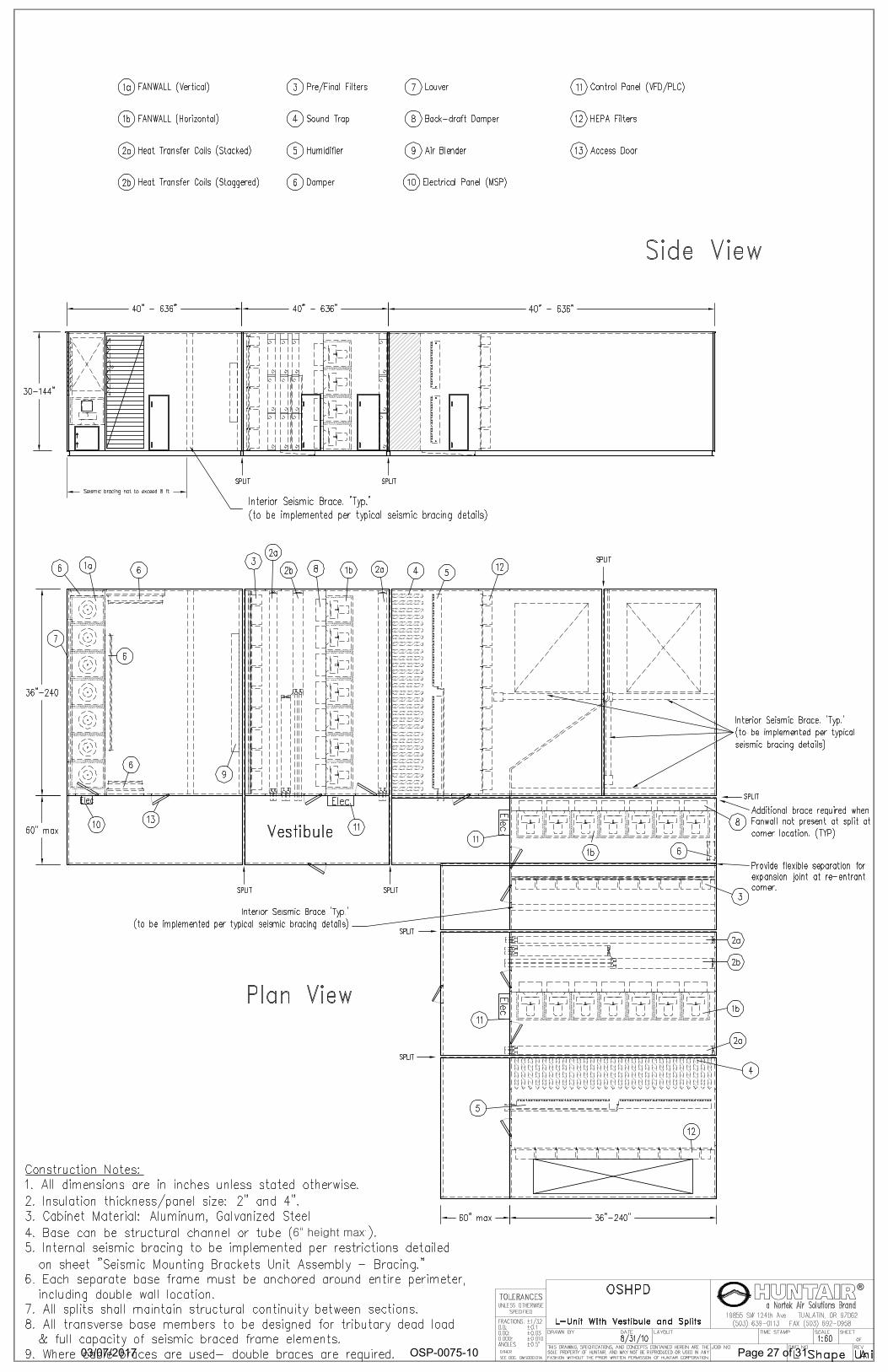
6" height max
03/07/2017
OSP-0075-10
Page 27 of 31
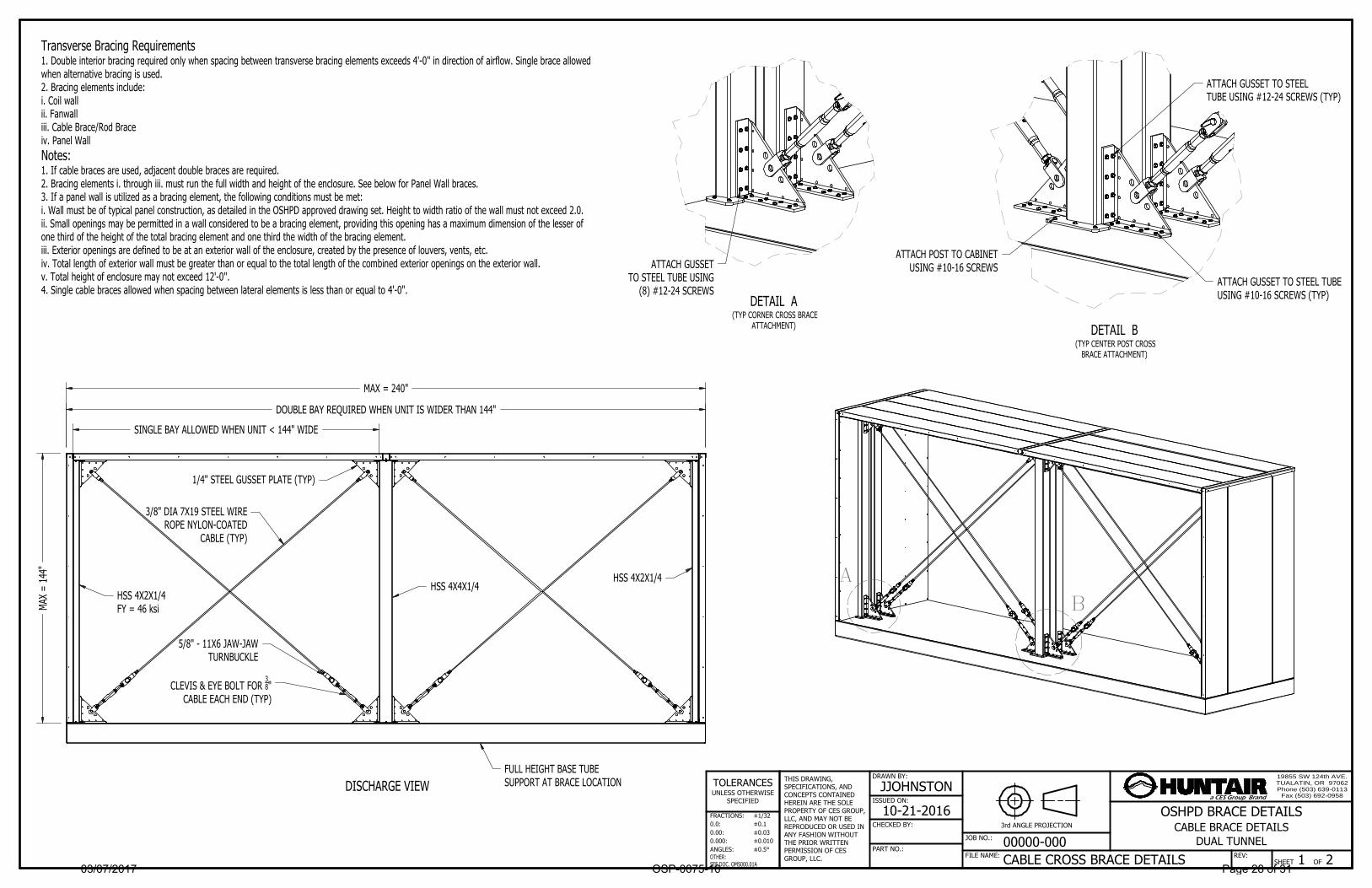
DISCHARGE VIEW
DETAIL A (TYP CORNER CROSS BRACE
ATTACHMENT) DETAIL B (TYP CENTER POST CROSS
BRACE ATTACHMENT)
19855 SW 124th AVE.TUALATIN, OR 97062Phone (503) 639-0113
Fax (503) 692-0958
JOB NO.:
SHEET 1 OF 2 CABLE CROSS BRACE DETAILSFILE NAME:
THIS DRAWING, SPECIFICATIONS, AND CONCEPTS CONTAINED HEREIN ARE THE SOLE PROPERTY OF CES GROUP, LLC, AND MAY NOT BE REPRODUCED OR USED IN ANY FASHION WITHOUT THE PRIOR WRITTEN PERMISSION OF CES GROUP, LLC.
DRAWN BY:
JJOHNSTON
10-21-2016ISSUED ON:
3rd ANGLE PROJECTIONCHECKED BY:
PART NO.:REV:
FRACTIONS:0.0:0.00: 0.000: ANGLES:
TOLERANCESUNLESS OTHERWISE
SPECIFIED a CES Group Brand
OSHPD BRACE DETAILS
00000-000CABLE BRACE DETAILS
DUAL TUNNEL
±1/32±0.1±0.03 ±0.010 ±0.5°
OTHER:SEE DOC. OMS000.01A
AB
ATTACH GUSSETTO STEEL TUBE USING
(8) #12-24 SCREWSATTACH GUSSET TO STEEL TUBEUSING #10-16 SCREWS (TYP)
ATTACH GUSSET TO STEELTUBE USING #12-24 SCREWS (TYP)
ATTACH POST TO CABINETUSING #10-16 SCREWS
MAX
= 14
4"
SINGLE BAY ALLOWED WHEN UNIT < 144" WIDE
DOUBLE BAY REQUIRED WHEN UNIT IS WIDER THAN 144"
MAX = 240"
1/4" STEEL GUSSET PLATE (TYP)
3/8" DIA 7X19 STEEL WIREROPE NYLON-COATED
CABLE (TYP)
5/8" - 11X6 JAW-JAWTURNBUCKLE
CLEVIS & EYE BOLT FOR 38"
CABLE EACH END (TYP)
HSS 4X4X1/4HSS 4X2X1/4
HSS 4X2X1/4FY = 46 ksi
FULL HEIGHT BASE TUBESUPPORT AT BRACE LOCATION
Transverse Bracing Requirements1. Double interior bracing required only when spacing between transverse bracing elements exceeds 4'-0'' in direction of airflow. Single brace allowedwhen alternative bracing is used.2. Bracing elements include:i. Coil wallii. Fanwalliii. Cable Brace/Rod Braceiv. Panel WallNotes:1. If cable braces are used, adjacent double braces are required.2. Bracing elements i. through iii. must run the full width and height of the enclosure. See below for Panel Wall braces.3. If a panel wall is utilized as a bracing element, the following conditions must be met:i. Wall must be of typical panel construction, as detailed in the OSHPD approved drawing set. Height to width ratio of the wall must not exceed 2.0.ii. Small openings may be permitted in a wall considered to be a bracing element, providing this opening has a maximum dimension of the lesser of one third of the height of the total bracing element and one third the width of the bracing element.iii. Exterior openings are defined to be at an exterior wall of the enclosure, created by the presence of louvers, vents, etc.iv. Total length of exterior wall must be greater than or equal to the total length of the combined exterior openings on the exterior wall.v. Total height of enclosure may not exceed 12'-0''.4. Single cable braces allowed when spacing between lateral elements is less than or equal to 4'-0".
03/07/2017
OSP-0075-10
Page 28 of 31

19855 SW 124th AVE.TUALATIN, OR 97062Phone (503) 639-0113
Fax (503) 692-0958
JOB NO.:
SHEET 2 OF 2 CABLE CROSS BRACE DETAILSFILE NAME:
THIS DRAWING, SPECIFICATIONS, AND CONCEPTS CONTAINED HEREIN ARE THE SOLE PROPERTY OF CES GROUP, LLC, AND MAY NOT BE REPRODUCED OR USED IN ANY FASHION WITHOUT THE PRIOR WRITTEN PERMISSION OF CES GROUP, LLC.
DRAWN BY:
JJOHNSTON
10-21-2016ISSUED ON:
3rd ANGLE PROJECTIONCHECKED BY:
PART NO.:REV:
FRACTIONS:0.0:0.00: 0.000: ANGLES:
TOLERANCESUNLESS OTHERWISE
SPECIFIED a CES Group Brand
OSHPD BRACE DETAILS
00000-000CABLE BRACE DETAILS
±1/32±0.1±0.03 ±0.010 ±0.5°
OTHER:SEE DOC. OMS000.01A
DOW
N 90
°
DOWN 90°
.250
.625
.2501.000
2.000
2.000
2.000
.375
.875 WELD
8.000
8.000
2.000
7.774
1.774
9.549
1.774 7.774
9.549
3/16"
GUSSET DETAIL
03/07/2017
OSP-0075-10
Page 29 of 31

Huntair Standard Operating Procedure
Standard Tube Base Design
Created 7/16/10
Doc. Page 1 of 2
SOP# DES0002a
SOP 1.0 Purpose
The purpose of this document is to establish a standard for base designs.
2.0 Scope This document is to set the standards to which all base designs are to be modeled after.
3.0 Definitions and Acronyms OD – Outside Dimension.
4.0 Standard Dimension For Tube Bases: Reference Figure 1 on page 2 4.1 Priority 1:
4.1.1 “A” dimension should not exceed 96 inches max 4.1.2 “B” dimension should be 24 inches or less. (Optimal)
4.2 Priority 2: 4.2.1 “C” dimension should not exceed 36 inches max. If exceeds 36 inches,
the dimensions defaults back to 24 inches. 4.2.2 “D” dimension should not exceed 36 inches max.
4.3 “E” dimensions are the unit OD.
5.0 Standard Construction For Tube Bases: 5.1 3/16 inch wall thickness.
5.2 Full height members up to 8 inches under Fanwall and Drain Pans.
5.3 Large members are used for the outside width and length as well as the inside widths. Reference Figure 1
5.4 When using a 2 inch wall construction, use a 1 inch by 1 inch 16 gauge angle to support the flooring. Reference Figure 2
5.5 When using a 4 inch wall construction, use a 1 inch by 3 inch 16 gauge angle to support the flooring. Reference Figure 2
5.6 Base flipping supports are too located in the center of the outside width members. END of Section For
Refe
renc
e Only
03/07/2017
OSP-0075-10
Page 30 of 31

Huntair Standard Operating Procedure
Standard Tube Base Design
Created 7/16/10
Doc. Page 2 of 2
SOP# DES0002a
SOP
PRIORITY 1
PRIORITY 2B
C
Figure 1
A
D
INSIDE WIDTH
E
OUTSIDE WIDTH
OUTSIDE LENGTH
E
Figure 2
2 INCH WALL 4 INCH WALL
1 x 1 inch Angle
1 x 3 inch Angle
TUBE FRAME
WALL FLOORING
For R
efere
nce O
nly
03/07/2017
OSP-0075-10
Page 31 of 31