osteobridge knee arthrodesis - elserver.combordo.com.ar.elserver.com/cirugia/merete-inf02.pdf ·...
TRANSCRIPT

From the «BioBall® Company»
OsteoBridge® Knee ArthrodesisThe modular system for the fusion of the knee joint
OsteoBridge® Family

2
Failed surgery (total knee replacement)
Arthrodesis or knee prostheses infections
Periprothetic fractures
Posttraumatic condition preventing an implantationof a knee prosthesis
Tumors in the proximity of the knee
Loosening or impairment of the pulley
01. OsteoBridge® Knee Arthrodesis
Advantages of the OsteoBridge® Knee Arthrodesis
Modularity of the system ensures flexible supply
Cementless and cemented implantation possible
Immediate mobility and analgesia possible
Simple handling, short time surgery
Indications
OsteoBridge® Knee Arthrodesis System
The OsteoBridge® Knee Arthrodesis serves as an implant to fuse the knee after failed
primary knee arthroplasty. The implant can also be used for bridging large bone defects
and the resection of the metaphysis of femur and tibia.
The System is available in three different variations:
I. Standard System II. Extended System III. Extended System PLUS
The Standard System consists of an angled spacer for bridging the damaged joint as well
as nails with a collar in different lengths and diameters to anchor the implant in the femur
and tibia. The nails are trumpet-shaped to optimize their stability into the damaged bone.
The Extended System contains additional nails that do not have a collar. These nails are
tapered and ribbed for a better anchorage in the bone. To bridge medium sized bone
defects spacers in the length of 20 mm without a collar and 30 mm with collar can be
clamped onto the nails.
The Extended System PLUS includes spacers in the lengths from 40 to 70 mm to bridge
particulary large bone defects. They can be connected with a spacer connector.
Page 6
Page 8
Page 10
Page 4/5

Merete Medical GmbH · Alt-Lankwitz 102 · 12247 Berlin · Germany · Phone: +49 (0)30-77 99 80-0 · Fax: +49 (0)30-77 99 80-177 · Mail: [email protected] · www.merete.de 3
Service package for the surgical assistance
Preoperative Planning
On the basis of the patient’s x-rays the sur-
geon will be provided with a preoperative
planning. Necessary implants will be selec-
ted and a graphical exposition of the propo-
sed provision can be drawn.
Supply
For the first surgeries all necessary implants
and instruments will be provided on a loan
basis.
In-House Training
Before the Surgery our product specialist
demonstrates the use of the instruments
and implants and performs saw bone trai-
ning for your staff.
Surgical Assistance
A Merete product specialist attends the sur-
gery and assists the assembly and instru-
mentation of the implants.
02. Service Package for Surgical Assistance

4
03. Properties and System Structure
Cementless and cemented implantation possible•
Primary stability is achieved by pressfit and a partly tapered, wedge-shaped nail de-sign with radiating ribs
•
Rotational stability by distal interlocking screws, static or dynamic•
Secure secondary stability due to biological integration of the prosthesis stem into the bone structure (osseointegration) stimulated by a roughened titanium surface
•
All implant components are made of titanium alloy (TiAl6V4)•
Adjustment of the extension/flexion and valgus/varus positioning of the joint by ro-tation of the angled spacer
•
Trial nails and a trial spacer for an intraoperative selection of implant components•
Hollow spacer shells can be used as a carrier of antibiotics as well as bone graft for an active stimulation of bone growth
•
The modularity of the system enables intraoperative adaption to the particular bone defect by using variable spacer lengths and spacer combinations.
•
OsteoBridge® Knee Arthrodesis System
Spacer in den Längen 20 und 30 mm
Nail with Collar
Angled Spacer
Interlocking Screws
Standard System
I. Standard System – Basic Supply
Clamping Screws

Merete Medical GmbH · Alt-Lankwitz 102 · 12247 Berlin · Germany · Phone: +49 (0)30-77 99 80-0 · Fax: +49 (0)30-77 99 80-177 · Mail: [email protected] · www.merete.de 5
OsteoBridge® Knee Arthrodesis System
Interlocking Screws
Clamping ScrewsSpacer Connector
Extended spacer
II. Extended System – Flexible Supply
Nail without Collar
Spacer with/without Collar
Extended SystemExtended System
PLUS
III. Extended System PLUS – Complete Supply

6
I. Standard System – Basic Supply
Angled Spacer
Nail with Collar
Interlocking Screws
x-ray templates are available for the preoperative planning.
Intraoperatively the surgeon can select the appropriate im-
plant sizes with the aid of trial components.
Interlocking screws with a diameter of 5 mm (lengths: 20 mm
to 56 mm) are provided in this package. They ensure a secure
fixation of the nails into the bone. The intruments are provi-
ded in two trays.
OsteoBridge® Knee Arthrodesis Standard System
Ref. GA04041
Spacer, sterileNails with Collar, sterile
Ø =10 Ø =12 Ø =14 Ø =16
L = 110 GA11011 GA11211 GA11411 GA11611
L = 130 GA11013 GA11213 GA11413 GA11613
L = 150* GA11015 GA11215 GA11415 GA11615
Diameter (mm)
Leng
th*
(mm
)
*Special lengths on request.
Diameter 5 mm
Interlocking screws
Ref. Length
GB35020 20 mm
GB35022 22 mm
GB35024 24 mm
GB35026 26 mm
GB35028 28 mm
Ref. Length
GB35030 30 mm
GB35032 32 mm
GB35034 34 mm
GB35036 36 mm
GB35038 38 mm
GB35040 40 mm
GB35042 42 mm
Ref. Length
GB35044 44 mm
GB35046 46 mm
GB35048 48 mm
GB35050 50 mm
GB35052 52 mm
GB35054 54 mm
GB35056 56 mm
Diameter 40 mm, Angle 10°
The implant is used for the fusion of the knee joint. Due to
the implant design of the OsteoBridge® Knee Arthrodesis
Standard System small and medium bone defects can be
treated. The system consists of an angled spacer for bridging
the damaged joint as well as a set of nails with collar in dif-
ferent lengths and diameters to anchor the implant in femur
and tibia. Due to previous TKRs the bone ends have become
trumpet shaped openings. The nails with collar adapt to this
anatomy very well.
The angled spacer enables a flexion of 10°. By rotating the
spacer the valgus-varus position of the joint can be adjusted.
Standard System
Length 50 mm

Merete Medical GmbH · Alt-Lankwitz 102 · 12247 Berlin · Germany · Phone: +49 (0)30-77 99 80-0 · Fax: +49 (0)30-77 99 80-177 · Mail: [email protected] · www.merete.de 7
Merete Medical GmbH likes to thank Prof. Dr. med. L. Rabenseifner, Stadtklinik Baden-Baden, Germany for the kind supply of the x-ray images.
Interlocking Screws
OsteoBridge® Knee Arthrodesis Standard System
Trial Implant Tray with 2 Trial Nails per Size
Case Study Standard System
Ref. GA91003
preoperative postoperative
Condition after failed TKR with infectionTemporary interim prosthesis
••
Treatment with OsteoBridge® Standard System•
Standard System

8
II. Extended System – Flexible Supply
The Extended System provides a second set of nails without
a collar. The taper shaped nails fit perfectly into the intra-
medullary canal. Ribs provide firm anchorage in the bone.
Spacers in the length 20 mm without collar and 30 mm with
collar can optionally be clamped onto these nails. A treat-
ment of defects up to 70 mm can be achieved.
Ref. GA04020 Ref. GA04030
Length 20 mm Length 30 mm
Nail without Collar
Spacer with Collar
Spacer without Collar
Ribs
Example of use: Application of a nail without collar and without additional spacer
Nails without Collar, sterile
Ø =14 Ø =16 Ø =18
L = 130 GA21413 GA21613 GA21813
L = 150 GA21415 GA21615 GA21815
L = 200 GA21420 GA21620 GA21820
Leng
th*
(mm
)
Diameter (mm) Diameter 40 mm, Angle 0°
Spacer without/with Collar, sterile
OsteoBridge® Knee Arthrodesis Extended System
*Special lengths on request.
Extended System

Merete Medical GmbH · Alt-Lankwitz 102 · 12247 Berlin · Germany · Phone: +49 (0)30-77 99 80-0 · Fax: +49 (0)30-77 99 80-177 · Mail: [email protected] · www.merete.de 9
Trial Implant Tray with 2 Trial Nails per size
OsteoBridge® Knee Arthrodesis Extended System
Ref. GA91004
Case Study Extended System
preoperative postoperative
Condition after failed TKR with infectionTemporary treatment with bone cement spacer
••
Treatment with OsteoBridge® Extended System•
Merete Medical GmbH likes to thank Dr. med. A. H. Tiemann, Berufsgenossenschaftliche Kliniken Bergmannstrost, Halle, Germany for the kind supply of the x-ray images.
Extended System

10
III. Extended System PLUS – Complete Supply
Spacer 70/60/50/40 mm, sterile
Large bone defects can be treated with the Extended System PLUS. Spacers in the lengths of 40 to 70 mm are
provided. These Spacers can be connected with a spacer
connector.
Spacer 70mm
60 mm
50 mm
40 mm
Spacer Connector
Spacer Connector, sterile
Diameter 40 mm, Angle 0˚
Ref. Length
GA04070 Spacer 70 mm
GA04060 Spacer 60 mm
GA04050 Spacer 50 mm
GA04040 Spacer 40 mm
Ref. GA40040
OsteoBridge® Knee Arthrodesis Extended System PLUS
Merete Medical GmbH likes to thank Prof. Dr. med. L. Rabenseifner Stadtklinik Baden-Baden, Germany for the kind supply of the x-ray images.
Case Study Extension PLUS
preoperative postoperative
Condition after failed TKR with infectionTemporary interim prosthesis
••
Treatment with OsteoBridge® Extended System PLUS•
EXTENS
ION
PLUS
Extended System PLU
S
Merete Medical GmbH · Alt-Lankwitz 102 · 12247 Berlin · Germany · Phone: +49 (0)30-77 99 80-0 · Fax: +49 (0)30-77 99 80-177 · Mail: [email protected] · www.merete.de 11
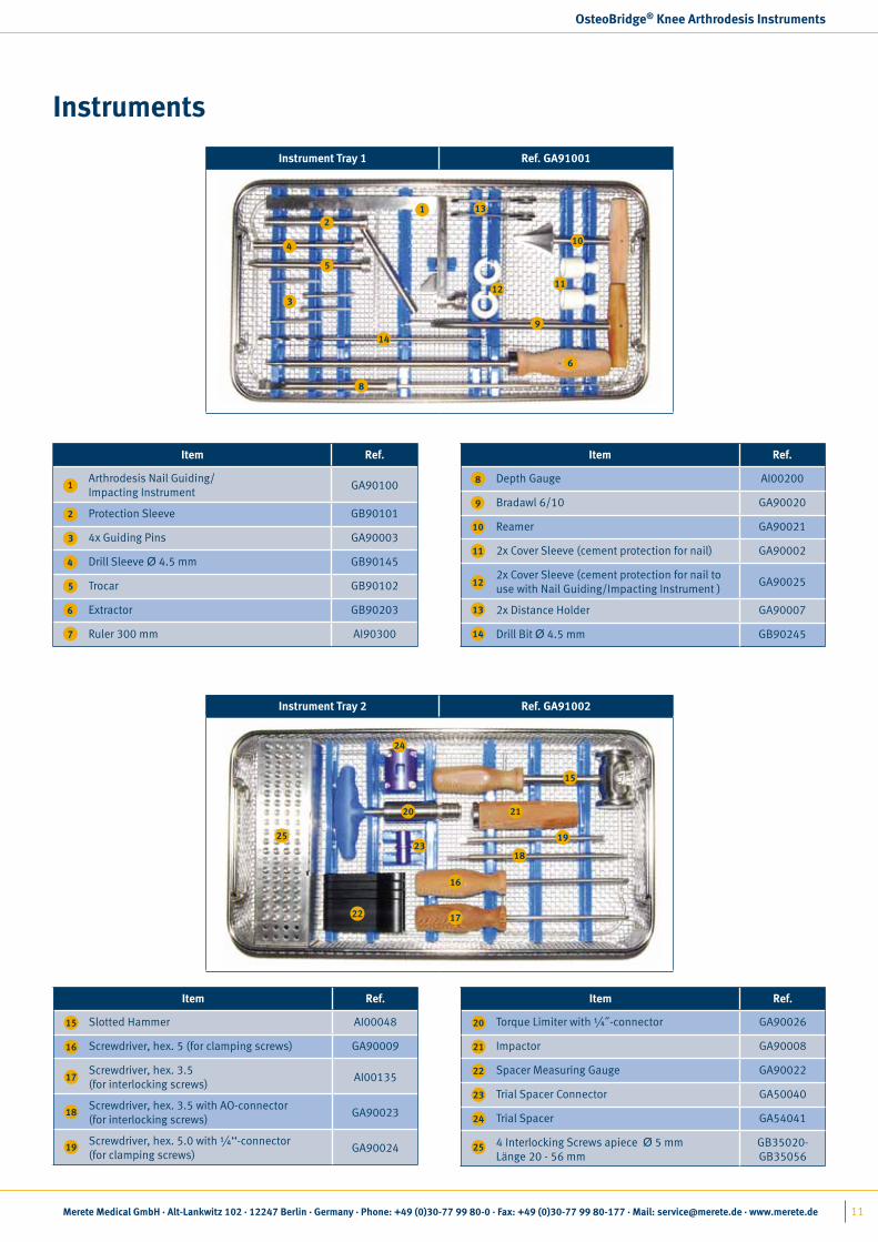
OsteoBridge® Knee Arthrodesis Instruments
Item Ref.
Arthrodesis Nail Guiding/Impacting Instrument
GA90100
Protection Sleeve GB90101
4x Guiding Pins GA90003
Drill Sleeve Ø 4.5 mm GB90145
Trocar GB90102
Extractor GB90203
Ruler 300 mm AI90300
1
2
3
4
5
6
7
Item Ref.
Slotted Hammer AI00048
Screwdriver, hex. 5 (for clamping screws) GA90009
Screwdriver, hex. 3.5(for interlocking screws)
AI00135
Screwdriver, hex. 3.5 with AO-connector (for interlocking screws)
GA90023
Screwdriver, hex. 5.0 with ¼‘‘-connector (for clamping screws)
GA90024
15
16
17
18
19
Instruments
Instrument Tray 1 Ref. GA91001
12
3
4
5
6
8
9
10
1112
13
14
Instrument Tray 2 Ref. GA91002
15
16
17
18
19
20 21
22
23
24
25
Item Ref.
Depth Gauge AI00200
Bradawl 6/10 GA90020
Reamer GA90021
2x Cover Sleeve (cement protection for nail) GA90002
2x Cover Sleeve (cement protection for nail to use with Nail Guiding/Impacting Instrument )
GA90025
2x Distance Holder GA90007
Drill Bit Ø 4.5 mm GB90245
8
9
10
11
12
13
14
Item Ref.
Torque Limiter with ¼˝-connector GA90026
Impactor GA90008
Spacer Measuring Gauge GA90022
Trial Spacer Connector GA50040
Trial Spacer GA54041
4 Interlocking Screws apiece Ø 5 mmLänge 20 - 56 mm
GB35020-GB35056
20
21
22
23
24
25

12
Prepare the intramedullary canal by opening it with
the bradawl or by drilling with an intramedullary
drill to the desired diameter. The diameter varies
depending on nail form and the principle of ancho-
ring.
Use the reamer and shape the bone in the proximal
area to implant a nail with collar.
Use the trial nails to check the adequate length and
diameter. Different nails can be used for tibia and femur. For checking the total length the trial spacer
has to be assembled. The upper spacer half-shell
is guided by two pins and fastened by two screws. Remove the trial components when the leg length
is accurate.
OsteoBridge® Knee Arthrodesis surgical technique
04.
2
3
Preparation of the Intramedullary Canal and Implant Selection
11
Nail with Collar Nail without Collar
Cemented2 to 4 mm larger than nominal diameter
2 mm larger than nominal diameter
Cementlessnominal diameter 2 mm smaller than
nominal diameter
OsteoBridge® Knee Arthrodesis Surgical Technique

Merete Medical GmbH · Alt-Lankwitz 102 · 12247 Berlin · Germany · Phone: +49 (0)30-77 99 80-0 · Fax: +49 (0)30-77 99 80-177 · Mail: [email protected] · www.merete.de 13
Check the position of the nails inside the spacer.
The nails have to be flush with the window in the
upper half-shell.
If the angled spacer ist not long enough to bridge
the defect, the length of an additional spacer can
be determined with the Spacer Measuring Gauge.
For a better allocation of trial components and im-
plants the trial nails are labeled with pictograms
of a dice indicating the diameter of the nail. The
pictogram with the corresponding number of the
dice can also be found on the product label.
To remove the trial nails use the extractor and slot-
ted hammer. Insert the extractor into the proximal
thread of the nail.
OsteoBridge® Knee Arthrodesis surgical technique
5
7
6
Ø 10 mm Ø 18 mmØ 12 mm Ø 14 mm Ø 16 mm
4

14
When using interlocking screws the drill holes in
the nail have to be positioned in the frontal plane,
for medial insertion of the screws. To insert the nail
correctly into the bone the nail guiding/impacting
instrument has to be plugged into the slot and the
locking screw screwed down until the nail is tighte-
ned to the nail guiding/impacting instrument.
Interlocking the nails: The length of the nails who-
se drill holes align is indicated on the nail guiding/
impacting instrument. The protection sleeve must
be inserted into the corresponding hole of the gui-
ding/impacting instrument, indicating the same
length as the nail, . The trocar peak center-punches
the drill hole. The trocar is removed and the drill
sleeve inserted.
OsteoBridge® Knee Arthrodesis surgical technique
1
Insertion of the Nails
2
3
20 mm
Attention: Clamping length of 20 mm minimumIf no interlocking screws are used the nails can be
inserted into the bone with the impactor. At least 20 mm clamping range has to remain outside the
bone.

Merete Medical GmbH · Alt-Lankwitz 102 · 12247 Berlin · Germany · Phone: +49 (0)30-77 99 80-0 · Fax: +49 (0)30-77 99 80-177 · Mail: [email protected] · www.merete.de 15
Use the drill bit Ø 4.5 mm to drill the interlocking
hole. Afterwards remove the drill sleeve. The depth gauge must be positioned onto the bone through
the protection sleeve. Push the small measuring
pole through the bone and hook to the opposite
cortical bone. Now the required length of the in-
terlocking screw can be read out at the end of the
measure.
Insert the interlocking screw of the correct length
into the protection sleeve and tighten with the
enclosed screwdriver. All nails are provided with
two drill holes for double interlocking. Remove
the static interlocking screw to achieve a dynami-
sation of the nail via the long hole. After insertion
of the screws remove the nail guiding/impacting
instrument. Do not start locking the second nail
before the locking of the first nail has been com-
pleted.
In case of a cemented insertion the cover sleeves
have to be placed onto the nails before starting to
insert the nail. The sleeves are removed once the
insertion of the nails has been completed. The dia-meter of the intramedullary canal should be 2 to 4 mm larger than for cementless insertion (Refering
to the table on page 12, picture 1). If the nail gui-
ding/impacting instrument is not used the covers
GA90002 must be used when cementing the nails.
OsteoBridge® Knee Arthrodesis surgical technique
4
5
6Locking Non-locking
Dynamic interlocking
Static interlocking
16
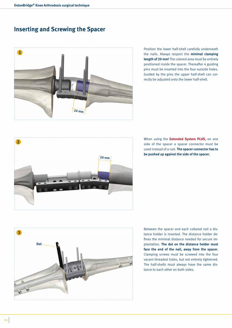
Position the lower half-shell carefully underneath
the nails. Always respect the minimal clamping length of 20 mm! The colored area must be entirely
positioned inside the spacer. Thereafter 4 guiding
pins must be inserted into the four outside holes.
Guided by the pins the upper half-shell can cor-
rectly be adjusted onto the lower half-shell.
Between the spacer and each collared nail a dis-
tance holder is inserted. The distance holder de-
fines the minimal distance needed for secure im-
plantation. The dot on the distance holder must face the end of the nail, away from the spacer. Clamping screws must be screwed into the four
vacant threaded holes, but not entirely tightened.
The half-shells must always have the same dis-
tance to each other on both sides.
When using the Extended System PLUS, on one
side of the spacer a spacer connector must be
used instead of a nail. The spacer connector has to be pushed up against the side of the spacer.
OsteoBridge® Knee Arthrodesis surgical technique
1
3
2
Inserting and Screwing the Spacer
20 mm
20 mm
Dot

Merete Medical GmbH · Alt-Lankwitz 102 · 12247 Berlin · Germany · Phone: +49 (0)30-77 99 80-0 · Fax: +49 (0)30-77 99 80-177 · Mail: [email protected] · www.merete.de 17
Replace the guiding pins by four more clamping
screws which are tightened down slightly. There-
after tighten the screws firmly with the torque li-
miting screwdriver. The torque limiting screwdriver
consists of two pieces that must be assembled
before use.
IMPORTANT! Follow the steps to tighten exactly! (see figure 5) Follow the instructions for the connection of the
spacer with 8 clamping screws carefully. The exact execution of these steps is required to achieve a sufficient clamping and the necessary rotational stability.
First the 4 inner clam-ping screws must be tightened in the defi-ned order.
Inside
Then the 4 outer clam-ping screws have to be tightened in the defi-ned order.
Outside
ATTENTION!
Repeat the whole procedure 3 times!
OsteoBridge® Knee Arthrodesis surgical technique
1. 4.
3. 2.
7. 6.
5. 8.
5
4
! All screws have to be tightened with the torque limiting screwdriver in the given order.
IMPORTANT! Repeat this precedure 3 times to re-tighten the screws!!

18
When using a spacer with the length of 40 mm to
70 mm of the Extended System PLUS this spacer
has to be assembled between the spacer connec-
tor and the nail only after the angled spacer is fully
mounted.
When using a spacer with the length of 20 mm or
30 mm of the Extended System it has to be posi-
tioned onto the clamping area of the nail without
collar and screwed in place. Do not clamp the spa-
cer onto the tapered part of the nail.
ATTENTION: The part of the nail left outside of the bone has to have a length of 40 - 50 mm!
OsteoBridge® Knee Arthrodesis surgical technique
6
5
40 - 50 mm
20 mm

Merete Medical GmbH · Alt-Lankwitz 102 · 12247 Berlin · Germany · Phone: +49 (0)30-77 99 80-0 · Fax: +49 (0)30-77 99 80-177 · Mail: [email protected] · www.merete.de 19
OsteoBridge® Family
OsteoBridge® Family
OsteoBridge® Resection Hip Prosthesis
Product Forecast – Development in Progress
OsteoBridge® Metaphysic Supply
OsteoBridge® Diaphysis The modular diaphyseal endoprosthesis for the
long term stabilisation of segmental bone de-
fects and bone resections in humerus, femur and tibia

ENO
A ·
09-2
009
· All
righ
ts re
serv
ed. ·
Cov
er: c
orel
lio ·
Foto
lia.d
e
Merete Medical GmbHAlt-Lankwitz 102
12247 Berlin · Germany
Phone: +49 (0)30 77 99 80-0
Fax: +49 (0)30 76 68 03 61
www.merete.de