otc 19550 overcoming weight transfer challenges in · pdf fileotc 19550 overcoming weight...
TRANSCRIPT

OTC 19550
Overcoming Weight Transfer Challenges in Complex, Shallow, Extended Reach Wells on Alaska's North Slope Randy Thomas, Dennis Hartwig, Steve McKeever, ConocoPhillips Alaska, Inc.; Dave Egedahl, ASRC Energy Services E&P Technology, Inc.; John Patton, Keith Holtzman, Halliburton–Sperry Drilling Services; Lee Smith, Halliburton-Security DBS/Alaskan Energy Resources
Copyright 2008, Offshore Technology Conference This paper was prepared for presentation at the 2008 Offshore Technology Conference held in Houston, Texas, U.S.A., 5–8 May 2008. This paper was selected for presentation by an OTC program committee following review of information contained in an abstract submitted by the author(s). Contents of the paper have not been reviewed by the Offshore Technology Conference and are subject to correction by the author(s). The material does not necessarily reflect any position of the Offshore Technology Conference, its officers, or members. Electronic reproduction, distribution, or storage of any part of this paper without the written consent of the Offshore Technology Conference is prohibited. Permission to reproduce in print is restricted to an abstract of not more than 300 words; illustrations may not be copied. The abstract must contain conspicuous acknowledgment of OTC copyright.
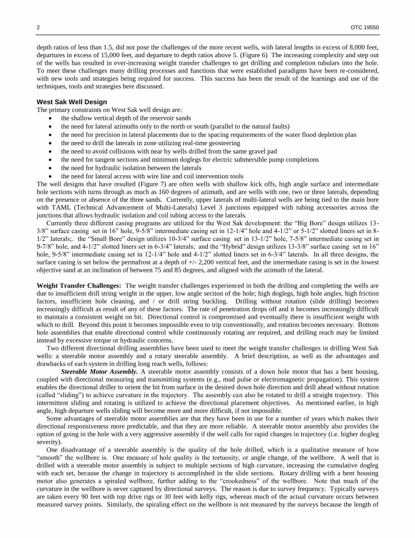
Abstract The complex wells currently being constructed to develop the West Sak Field on the North Slope of Alaska (Figure 1) are
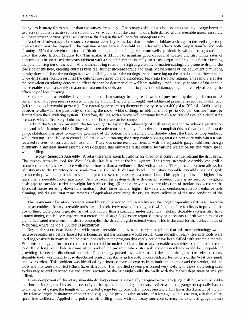
approaching the limits of extended reach drilling technology (Figure 2). Due to the shallow vertical depth and long horizontal
departure of these wells, the ability to effectively transfer weight while drilling and running tubulars can be very challenging.
This paper discusses the reasons those challenges exist, and the tools, techniques and learnings employed over the past seven
years to successfully solve weight transfer challenges in this remote, environmentally sensitive area, including steerable
motor assemblies, rotary steerable drilling assemblies, collaborative planning, on site drilling engineers, torque and drag
reduction devices, fluid additives, vibrating down hole tools, and liner running with multiple trips. These learnings enabled
the recent drilling and completion of a West Sak well with a total measured depth of 19,750 feet at a vertical depth of 3,055
feet. This well, with a horizontal departure of 18,472 feet and two laterals with lengths in excess of 7,500 feet, has a
departure to depth ratio in excess of six.
Background The West Sak field is within the Kuparuk River Unit on the North Slope of Alaska (Figure 1). The West Sak heavy oil sands
contain highly viscous oil due to the low gravity of the crude (10 to 22 degrees API) and the low reservoir temperatures
(caused by both the extreme northern latitude and the shallow (3,000 to 4,000 vertical feet) burial depth below 1,800 feet of
permafrost in the overburden.) The West Sak reservoir has three primary sandstone targets: the “A2”, the “B” and the “D”
intervals. The West Sak sands are “very-fine” to “fine” grained, single and amalgamated sandstone/siltstone beds. Geologic
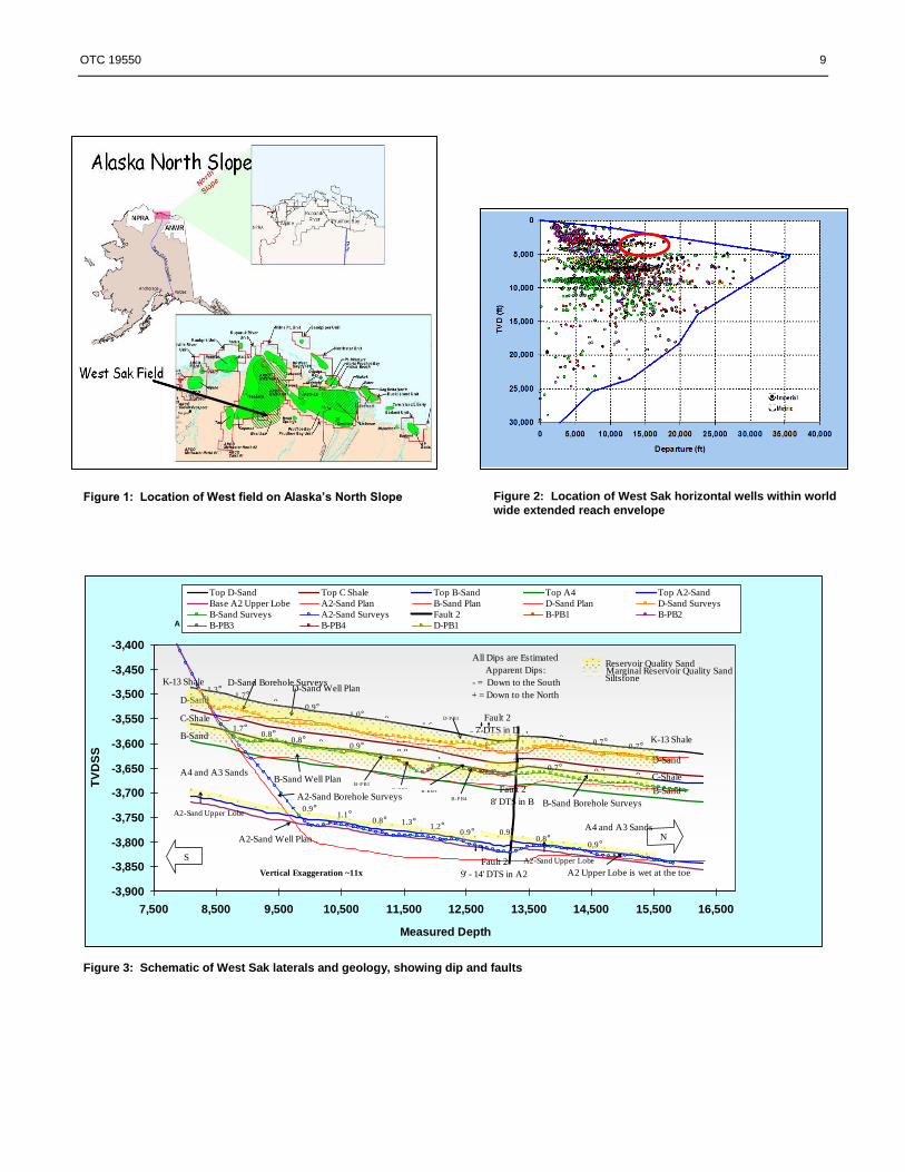
challenges while drilling include numerous fault crossings along the wellbore (Figure 3) as well as random encounters with
calcite-cemented spheroids, also known as concretions (Figure 4). The concretions are much harder than the reservoir sand,
having compressive strength of 25,000 pounds per square inch (psi) versus 500 psi for the reservoir sand. These concretions
drill much more slowly than the adjacent sand which accelerates wear on the bit, the bottom hole assembly, and the drill
string. This difference in hardness can also cause the drill bit to deflect off of the concretions resulting in unwanted severe
doglegs. Such doglegs make it difficult to maintain directional control, increase torque and drag, and can cause down hole
tool damage.
Early West Sak development consisted of stimulated vertical wells on a 40-acre water flood pattern with typical
production rates of 150-250 barrels of oil per day. Because the North Slope is a remote and fragile arctic environment
operators are motivated to develop progressively larger reservoir areas with increasingly smaller surface footprints (Figure 5).
With the evolution in horizontal and multi-lateral drilling technology, the development plan has progressed from the early
vertical wells to the current extended reach multi-lateral injectors and producers with horizontal and undulating slotted liner
completions (Targac, et al, 2005). While this progression in the development plan has reduced the overall per barrel
development cost, as well as the impact on the natural environment, it has presented challenges in drilling and completing the
wells. To date 59 horizontal wells have been completed in the West Sak field, and the wells have evolved to longer and more
difficult designs. One way in which the difficulty of these wells can be compared with one another is the Directional
Difficulty Index (DDI), a calculation that takes into account the major contributing factors that affect the directional difficulty
of a well (Oag, A. et al, 2000). Calculated thusly, DDI = Log [MD x Horizontal Departure x Tortuosity / TVD], the West
Sak horizontal wells have had DDI values that have ranged from 6.35 in the early days to 7.66 on recent wells, more than a
ten fold increase in difficulty (Table 1). Similarly the early wells, with departures of less than 5,000 feet and departure to
2 OTC 19550
depth ratios of less than 1.5, did not pose the challenges of the more recent wells, with lateral lengths in excess of 8,000 feet,
departures in excess of 15,000 feet, and departure to depth ratios above 5. (Figure 6) The increasing complexity and step out
of the wells has resulted in ever-increasing weight transfer challenges to get drilling and completion tubulars into the hole.
To meet these challenges many drilling processes and functions that were established paradigms have been re-considered,
with new tools and strategies being required for success. This success has been the result of the learnings and use of the
techniques, tools and strategies here discussed.
West Sak Well Design The primary constraints on West Sak well design are:
the shallow vertical depth of the reservoir sands
the need for lateral azimuths only to the north or south (parallel to the natural faults)
the need for precision in lateral placements due to the spacing requirements of the water flood depletion plan
the need to drill the laterals in zone utilizing real-time geosteering
the need to avoid collisions with near by wells drilled from the same gravel pad
the need for tangent sections and minimum doglegs for electric submersible pump completions
the need for hydraulic isolation between the laterals
the need for lateral access with wire line and coil intervention tools
The well designs that have resulted (Figure 7) are often wells with shallow kick offs, high angle surface and intermediate
hole sections with turns through as much as 160 degrees of azimuth, and are wells with one, two or three laterals, depending
on the presence or absence of the three sands. Currently, upper laterals of multi-lateral wells are being tied to the main bore
with TAML (Technical Advancement of Multi-Laterals) Level 3 junctions equipped with tubing accessories across the
junctions that allows hydraulic isolation and coil tubing access to the laterals.
Currently three different casing programs are utilized for the West Sak development: the “Big Bore” design utilizes 13-
3/8” surface casing set in 16” hole, 9-5/8” intermediate casing set in 12-1/4” hole and 4-1/2” or 5-1/2” slotted liners set in 8-
1/2” laterals;. the “Small Bore” design utilizes 10-3/4” surface casing set in 13-1/2” hole, 7-5/8” intermediate casing set in
9-7/8” hole, and 4-1/2” slotted liners set in 6-3/4” laterals; and the “Hybrid” design utilizes 13-3/8” surface casing set in 16”
hole, 9-5/8” intermediate casing set in 12-1/4” hole and 4-1/2” slotted liners set in 6-3/4” laterals. In all three designs, the
surface casing is set below the permafrost at a depth of +/- 2,200 vertical feet, and the intermediate casing is set in the lowest
objective sand at an inclination of between 75 and 85 degrees, and aligned with the azimuth of the lateral.
Weight Transfer Challenges: The weight transfer challenges experienced in both the drilling and completing the wells are
due to insufficient drill string weight in the upper, low angle section of the hole; high doglegs, high hole angles, high friction
factors, insufficient hole cleaning, and / or drill string buckling. Drilling without rotation (slide drilling) becomes
increasingly difficult as result of any of these factors. The rate of penetration drops off and it becomes increasingly difficult
to maintain a consistent weight on bit. Directional control is compromised and eventually there is insufficient weight with
which to drill. Beyond this point it becomes impossible even to trip conventionally, and rotation becomes necessary. Bottom
hole assemblies that enable directional control while continuously rotating are required, and drilling reach may be limited
instead by excessive torque or hydraulic concerns. Two different directional drilling assemblies have been used to meet the weight transfer challenges in drilling West Sak
wells: a steerable motor assembly and a rotary steerable assembly. A brief description, as well as the advantages and
drawbacks of each system in drilling long reach wells, follows:
Steerable Motor Assembly. A steerable motor assembly consists of a down hole motor that has a bent housing,
coupled with directional measuring and transmitting systems (e.g., mud pulse or electromagnetic propagation). This system
enables the directional driller to orient the bit from surface in the desired down hole direction and drill ahead without rotation
(called “sliding”) to achieve curvature in the trajectory. The assembly can also be rotated to drill a straight trajectory. This
intermittent sliding and rotating is utilized to achieve the directional placement objectives. As mentioned earlier, in high
angle, high departure wells sliding will become more and more difficult, if not impossible.
Some advantages of steerable motor assemblies are that they have been in use for a number of years which makes their
directional responsiveness more predictable, and that they are more reliable. A steerable motor assembly also provides the
option of going in the hole with a very aggressive assembly if the well calls for rapid changes in trajectory (i.e. higher dogleg
severity).
One disadvantage of a steerable assembly is the quality of the hole drilled, which is a qualitative measure of how
“smooth” the wellbore is. One measure of hole quality is the tortuosity, or angle change, of the wellbore. A well that is
drilled with a steerable motor assembly is subject to multiple sections of high curvature, increasing the cumulative dogleg
with each set, because the change in trajectory is accomplished in the slide sections. Rotary drilling with a bent housing
motor also generates a spiraled wellbore, further adding to the “crookedness” of the wellbore. Note that much of the
curvature in the wellbore is never captured by directional surveys. The reason is due to survey frequency. Typically surveys
are taken every 90 feet with top drive rigs or 30 feet with kelly rigs, whereas much of the actual curvature occurs between
measured survey points. Similarly, the spiraling effect on the wellbore is not measured by the surveys because the length of
OTC 19550 3
the cycles is many times smaller than the survey frequency. The survey calculation also assumes that any change between
two survey points is achieved in a smooth curve, which is not the case. Thus a hole drilled with a steerable motor assembly
will have unseen tortuosity that will increase the drag in the well bore for subsequent runs.
Another disadvantage of the steerable motor assembly is the fact that in order to initiate a change in the well trajectory,
pipe rotation must be stopped. The negative aspect here is two-fold as it adversely affects both weight transfer and hole
cleaning. Effective weight transfer is difficult on high angle and high departure wells, particularly without string rotation to
break the static friction (Figure 10). This makes it difficult to maintain good directional control and also limits rates of
penetration. The increased tortuosity inherent with a steerable motor assembly increases torque and drag, thus further limiting
the potential step out of the well. And without string rotation in high angle wells, formation cuttings are prone to drop to the
low side of the hole, creating cuttings beds that further increase torque and drag. Measurement of the equivalent circulating
density does not show the cuttings load while sliding because the cuttings are not traveling up the annulus in the flow stream.
Once drill string rotation resumes the cuttings are stirred up and introduced back into the flow regime. This rapidly elevates
the equivalent circulating density, an effect that can be detrimental to wellbore stability. Additionally, because of the bend in
the steerable motor assembly, maximum rotational speeds are limited to prevent tool damage, again adversely affecting the
efficiency of hole cleaning.
Steerable motor assemblies have the additional disadvantage in long reach wells of pressure drop through the motor. A
certain amount of pressure is required to operate a motor (i.e. pump through), and additional pressure is required to drill with
(referred to as differential pressure). The operating pressure requirement can vary between 400 psi to 700 psi. Additionally,
in order to allow for the possibility of stalling the motor while drilling, an additional 300 psi to 600 psi “cushion” must be
factored into the circulating system. Therefore, drilling with a motor will consume from 15% to 30% of available circulating
pressure, which effectively limits the amount of fluid that can be pumped.
Early in the West Sak program, the team sought to exploit the advantage of drill string rotation to enhance penetration
rates and hole cleaning while drilling with a steerable motor assembly. In order to accomplish this, a down hole adjustable
gauge stabilizer was used to vary the geometry of the bottom hole assembly and thereby adjust the build or drop tendency
while rotating. The ability to control inclination while rotating the string made stopping rotation necessary only when it was
required to steer for corrections in azimuth. There was some technical success with the adjustable gauge stabilizer, though
eventually a steerable motor assembly was designed that allowed similar control by varying weight on bit and rotary speed
while drilling.
Rotary Steerable Assembly. A rotary steerable assembly allows for directional control while rotating the drill string.
The system currently used for West Sak drilling is a “point-the-bit” system. The rotary steerable assembly can drill a
smoother, non-spiraled wellbore with less tortuosity than a wellbore drilled with a motor. This particular system allows for
adjustments to the trajectory to be made “on the fly” while drilling ahead. The rotary steerable assembly has negligible
pressure drop, with no potential to stall and spike the system pressure as a motor does. This typically allows for higher flow
rates than a steerable motor assembly. And because the system drills with constant rotation, there is no need for weighted
push pipe to provide sufficient weight for slide drilling. (Rotation provides another direction of motion to overcome the
frictional forces resisting down hole motion). Both these factors, higher flow rate and continuous rotation, enhance hole
cleaning, and the resulting measurements of equivalent circulating density are more indicative of the true condition of the
hole.
The limitations of a rotary steerable assembly revolve around tool reliability and the dogleg capability relative to steerable
motor assemblies. Rotary steerable tools are still a relatively new technology, and while the tool reliability is improving, the
use of these tools poses a greater risk of tool failure than a steerable motor assembly. Rotary steerable systems also have
limited dogleg capability compared to a motor, and if large doglegs are required it may be necessary to drill with a motor or
plan a dedicated motor run in order to accomplish the demanding directional work. This is the case for the surface holes of
West Sak, where the top 1,800 feet is permafrost
Key to the success at West Sak with rotary steerable tools was the early recognition that this new technology would
require repeated use before hoped for efficiencies and performance would result. Consequently, rotary steerable tools were
used aggressively in many of the hole sections early in the program that easily could have been drilled with steerable motors.
With this strategy performance characteristics could be understood, and the rotary steerable assemblies could be counted on
to drill the long reach hole sections at the end of the program where steerable motor assemblies would be incapable of
providing the needed directional control. This strategy proved invaluable in that the initial design of the selected rotary
steerable tools was found to lose directional control capability in the soft, unconsolidated formations of the West Sak sands
and overburden. This problem was identified by a focused team of experts from both the operator and the vender, and the
tools and bits were modified (Chen, S., et al, 2008). The modified system performed very well, with those tools being used
exclusively to drill intermediate and lateral sections on the last eight wells, the wells with the highest departures of any yet
drilled.
A key component of the rotary steerable drilling system is a specially designed extended-gauge drill bit, which is unlike
the short or long-gauge bits used previously in the upstream oil and gas industry. Whereas a long-gauge bit typically has up
to six inches of gauge, the length of an extended-gauge bit, by contrast, is about one and a half times the diameter of the bit.
The relative length to diameter of an extended-gauge bit provides the stability of a long-gauge bit, ensuring a high-quality,
spiral-free wellbore. Applied in a point-the-bit drilling mode with the rotary steerable system, the extended-gauge bit can

4 OTC 19550
provide a smoother, maximum-drift directional wellbore (Mason et al, 2005 and Stuart et al, 2003). For example, in a typical
West Sak performance, one 12-1/4” bit run in at 2,218 ft TVD, drilled 6,359 feet at a ROP of 185 ft/hr, while building
inclination from 73 degrees to 85 degrees and simultaneously turning azimuth from 152 to 183 degrees. It completed the
entire intermediate interval section to TD with no problems. Table 2 summarizes rotary steerable bit performance in West
Sak wells, and shows a total of approximately 388,000 feet has been drilled using this matched rotary steerable system.
There are a number of advantages in using a a rotary steerable assembly that will improve drilling performance. These
include a smoother wellbore, better hole cleaning, and greatly enhanced weight transfer capability (Alvord et al, 2005).
As with drilling the West Sak wells, there are weight transfer challenges in completing the multi-lateral wells. At
increased step outs it becomes difficult to perform the tasks required to mill the windows in the intermediate casing,
including orienting the whipstock and providing sufficient weight to shear the mills from the whipstock. Liners cannot be
run to total depth without rotation (Figures 8 and 9), and it becomes impossible to slide upper liner hangers into place on the
milled casing exits.
Weight Transfer Solutions. In constructing West Sak wells the solutions to the weight transfer challenges have been
collaborative planning, on site drilling engineers, torque and drag reduction devices, fluid lubricants and mud additives,
vibrating downhole tools, adjustable gauge stabilizers, rotary steerable drilling assemblies and liner running with multiple
trips. Each is discussed below.
Collaborative Planning Key to the success of constructing these complex wells has been collaborative planning. This approach incorporates input
from all aspects of well construction; with communication being paramount to identifying and capturing “lessons learned”.
The West Sak team uses the MaxWell process) to capture both the overall project and the individual well requirements
(Morgan, D., et al, 1999). Individuals from all aspects of the well design team, including geologic/geophysical, reservoir,
drilling, completions and production engineering groups, as well as the asset development team, meet weekly to discuss
requirements and collaborate in well planning sessions to balance risks, costs and benefits and arrive at the highest value
outcomes. In these sessions a directional well planner combines input from members of the team into a well trajectory that
achieves the agreed upon objectives. A directional plan will go though much iteration during the process, often times as a
result of various weight transfer challenges that may surface during the planning process. For example, on the wells with
high departures for the intermediate casing, well paths are designed to enable the surface casing to be run as deep possible to
provide as much well bore as possible with the lower friction factor of cased hole for the subsequent intermediate casing run.
Consequently, double build well paths have resulted, with the surface hole building to some average tangent angle less than
the critical angle (That angle at which the casing would no longer move down the hole due to its own weight (Payne et al,
1994).) of the surface casing, then the intermediate hole building to a second, higher tangent angle. Similarly, well
trajectories with sections of decreasing inclination in the intermediate hole are avoided, given that compressive buckling is
more likely to occur in these hole sections.
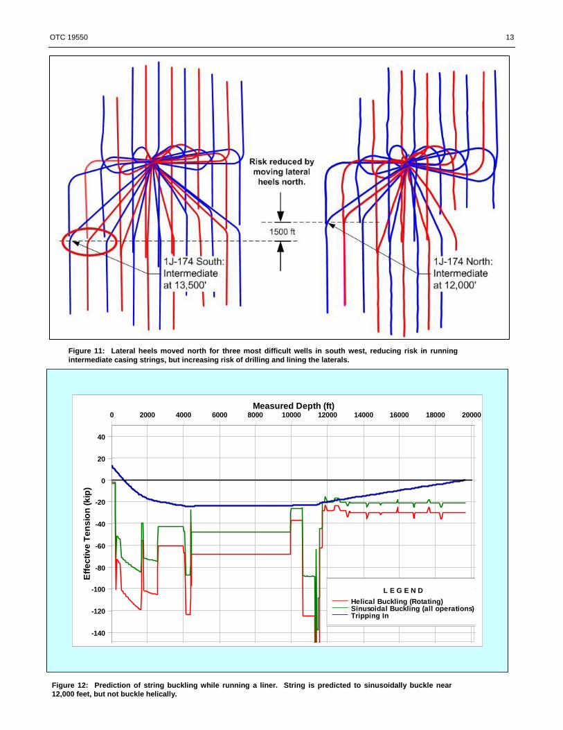
Collaborative planning was also key to reducing the risk of three wells in the south west corner of the West Sak
development from 1J pad. These wells as originally planned would have had intermediate casing runs to nearly 13,500 feet
at a vertical depth of 3,200 feet, runs which would require flotation or other non-conventional, high risk means. The planning
team, agreed to move the lateral heel targets 1,500 feet to the north, reducing the length of the intermediate casing runs, and
reducing the overall risk to the wells despite the longer laterals that resulte and the shift in value from the wells to the north,
with shorter laterals(Figure 11).
To ensure a planned design is successfully implemented, the operator contracts or employs the following drilling team
members: a field wide team leader; a senior planning engineer; a town based operations engineer; day and night rig site
drilling foremen, directional drillers;, mud engineers, MWD engineers, toolpushers, well site geologists; and rig site drilling
engineers. Daily operations meetings are held in which both the rig site and town based team members, as well as suppliers
and service providers, participate to discuss past, current, and upcoming operational issues. The rig team also holds rig site
daily operational meetings to discuss rig specific issues, and the rig crews participate in the “technical limits” process in order
to identify “lessons learned” and establish “best practices” which enable continual improvements to the operations.
With this collaborative planning process the weight transfer challenges of a given well can be identified early and
discussed by all parties involved. Potential solutions can be considered, and the costs, risks and benefits can be weighed
against one another, resulting in the solutions that yield the highest value.
Rig-Site Engineers, Data Collection, and Torque, Drag and Buckling Modeling Another key element in overcoming the challenges of weight transfer on West Sak wells has been the assignment of a drilling
engineer to work at the rig sites. Early in the horizontal program heavier push pipe had to be run on top of the strings used to
run sand control screens to overcome drag forces from the horizontal sections. These first wells, with horizontal departure to
vertical depth ratios of less than 2 to 1, were the first hint of the weight transfer challenges to come, and the decision was
made early in West Sak drilling to position engineers at the rig site to do torque and drag analysis as the wells become more
difficult.

OTC 19550 5
The rig site engineers do torque and drag analysis using a finite element software package to design the drilling and liner
running strings, placing drag reduction devices as needed to mitigate buckling and overcome drag. Additionally they
evaluate future wells in order to identify challenges, and monitor real-time operations in order to identify trends that may
require remediation, such as deteriorating hole conditions, and maintain a database of actual torque and drag data and
interpreted friction factors. With the initial running of sand control screens on the first West Sak laterals in the year 2000, the
need was identified for good torque and drag data so that the accuracy of the torque and drag models could be improved.
Reliable data needed to be captured in a consistent fashion. Discussions were held and decisions were made on what data
was to be collected and what method of collection was to be used. The result was standardized torque and drag data
collection procedures for the different operations, with collection overseen by the rig site engineers. While drilling the data is
collected at each connection (every 90 feet) and includes both on bottom torque, weight on bit, rotary speed, flow rate,
equivalent circulating density, and standpipe pressure, and off bottom torque and standpipe pressure, and the pick up, slack
off and rotating weight of the string. While tripping pipe or running casing and tubing, pick up weights and slack off weights
are recorded every 500 feet, with greater frequency if the operation requires it.
With increased lateral lengths and departures of the wells, oriented (slide) drilling became difficult towards the end of the
laterals. Thus rig site engineers started to model the lateral drilling strings as well as the liner running strings, determining
optimal placement of push pipe, other drag reduction devices, and premium liner connections. Comparing actual data to the
data predicted with a model, the engineers are able to identify whether sliding difficulty is attributable to drill string buckling
or to poor hole cleaning, or a combination of factors. The need for detailed modeling and close monitoring then progressed
to the drilling and casing of the intermediate and surface holes, and then to the completion strings of tubing and an electrical
submersible pump with cable.
Prior to each operation (drilling, casing and lining, running tubing) the rig site engineers construct a computer model
inputting the hole geometry and string. Through iteration the string is designed with the placement of premium liner
connections, friction reduction devices and / or heavy wall pipe so that the objective of the operation will be met. Such
modeling has shown that compressive buckling of strings while sliding and running liners will create drag sufficient to stop
downward motion of the string. By modeling the string at various locations in the well bore, drag reduction devices can be
properly placed to reduce or eliminate buckling (Figure 12). Once the models are constructed, while the operation is
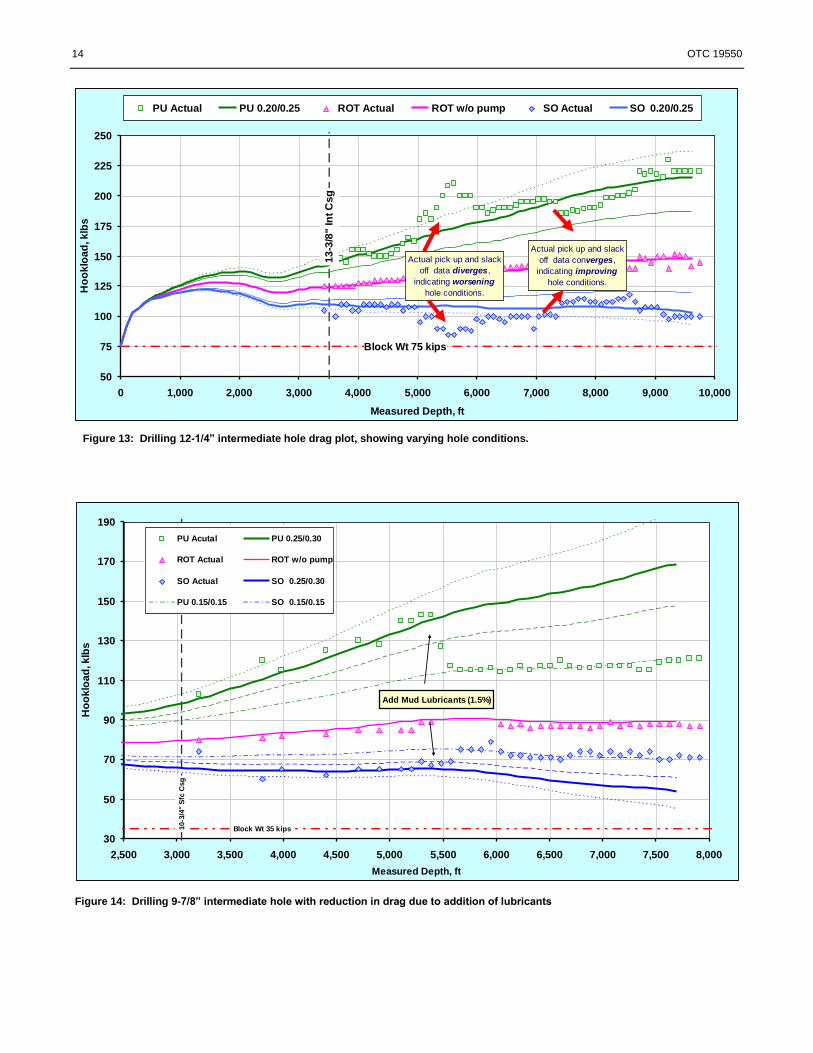
ongoing, the rig site engineers compare actual data against the computer models to reveal trends that indicate hole conditions,
including changing and unexpected friction factors (Figure 13). Then, once each operation is completed, they finalize the
models including the actual surveys and data over the entire wellbore and a “best fit” analysis is generated. The results of all
the models are saved and a central database is then updated with the “best fit” friction factors. This central database can then
be used to predict offset friction factors, manage current operations, identify future operations that may require additional
engineering for success, and determine the “technical limits” of future wells of increased difficulty.
Torque and Drag Reduction Devices In drilling and completing West Sak wells, several types of torque and drag reduction devices have been used and evaluated
while drilling and running casing and liners. Subs with drill pipe connections having non-rotating sleeves with metal rollers
in the axial direction were found to reduce cased hole friction factors by 50% over the section of cased hole where used, but
required valuable rig time for installation and removal, especially if more than one device per stand of pipe was used. Also
used on the drill pipe while drilling and running liners are devices that consist of a non-rotating polyurethane sleeve of
increased diameter that are held in place on the tube of the drill pipe with aluminum clamps. These tools have been effective
at reducing rotational and axial friction factors, reducing wear on drill pipe and casing, mitigating buckling by providing a
point of support in the middle of a joint of drill pipe. Like the drag reducing subs, though, these devices are limited to use on
drill pipe only in cased hole.
Solid bodied centralizers have been shown to present less drag than bow spring type centralizers, so they are used on
casing strings when additional drag reduction is needed, and exclusively on liner runs. Aluminum centralizers and
centralizers with welded blades run on upper liners were found to have failed when the first hydraulic isolation completion
assemblies were run across upper junctions. Large side forces and the sharp edges of the milled casing exit sliced the
centralizers off the liner, depositing junk and debris in the main bore below the junction. Extensive testing of centralizers
followed on a surface test fixture that allowed the application of side loads predicted by models. The result was the
qualification of one-piece, molded centralizers with no welds for use on the upper liners (Peterson et al, 2006). On
intermediate casing runs, roller centralizers have been used within the surface casing on the intermediate casing runs to
reduce drag, increasing the available weight to push the casing below through the open hole.
Fluid Lubricants, Mud Additives and Hole Cleaning Lubricants, nut plug, and drilling beads have provided some usefulness to weight transfer down hole. Lubricants have
proven very effective in reducing torque and drag, in some cases cutting down hole friction nearly in half while drilling the
intermediate hole section (Figure 14 and 15). Use of mud lubricants is limited by the concentration that can be carried in the
system without adversely affecting the mud properties. As a result, amounts typically approach, but don’t exceed 3% by
volume. Lubricants also are expensive and tend to be lost to cuttings removed from the mud. Therefore the lubricants are
held out until late in the hole section where the benefit of reduced friction is more necessary. Recently tests with a lubricant

6 OTC 19550
that acts with the water phase of the completion fluid (solid free oil base mud) has proven very effective in reducing torque
and drag and assisting the running of lateral liners. Nut plug and drilling beads have provided only limited benefit to weight
transfer down hole. They are most effective when spotted around the steerable motor assembly to provide weight for slide
drilling, but the drawback is that they are beneficial only for a short time, being removed from the mud system with
circulation. They also have the potential to plug down hole tools if not properly mixed prior to pumping.
The impact of hole cleaning on effective weight transfer has also come to be better understood. Current practices include
real time monitoring of hole cleaning through the use of annular pressure measuring tools in the bottom hole assemblies and
the monitoring of the equivalent circulating densities these tools deliver, as well as continual monitoring of the actual pick up
and slack off weights against those predicted with the torque and drag modeling. (Figure 13)
Vibrating Down Hole Tools Tools that axially vibrate the drill string have proven successful in drilling both the lateral and intermediate sections, allowing
farther reach with a steerable motor than would have been otherwise possible. A vibration tool is positioned in the drill string
so that when it vibrates, string weight is more easily transferred down hole. The drawbacks of the down hole vibration tool
are that there is a substantial pressure drop through the tool (much like a down hole motor) thus limiting the amount of flow
available for hole cleaning, and the larger tools used for the 12-1/4 inch intermediate hole create quite a bit of surface
vibration. Additionally, placement of the tool with relation to the bottom hole assembly and its expected effect is difficult to
model and predict.
Push Pipe The term “push pipe” refers to heavier pipe placed in the shallow, less inclined section of the hole to provide weight to push
the string along the lower more highly deviated section of the well bore. For drilling operations at West Sak heavy-weight
drill pipe and drill collars have been used as push pipe. The heavy weight drill pipe has been used alone, or with drill collars
to make “hybrid stands”. A “hybrid stand” is one joint of heavy-weight drill pipe on top of two drill collars, providing a
stand with the ease of handling on the rig comparable to a stand of heavy-weight drill pipe. In drilling “Small Bore” West
Sak wells with four inch drill pipe, five inch diameter drill collars were special ordered for use in “hybrids”.
There are several disadvantages of push pipe. The effectiveness of push pipe is rapidly lost as it moves through shallow
kickoff and build sections to the higher high angles below. The rig site engineers at West Sak generally limit the use of push
pipe in drill strings to that upper portion of the well where inclinations are less than sixty degrees, approximately the top
1,500 feet of the well. If push pipe is needed to drill more than 1,500 feet, then the push pipe must be pulled from the well
and replaced with standard pipe. Then drilling can start again with the push pipe on top. Another disadvantage of push pipe
is the reduced inner diameter of the heavy weight pipe and drill collars. This increases the pressure loss through the drill
string, and may require reduced flow rates to stay below surface pressure limits. These same reduced diameters were thought
to have caused detection problems for mud pulse measurement while drilling tools on some West Sak wells where hybrid
stands were used as push pipe. One last disadvantage of push pipe is the rig time involved in picking up and making up the
stands of hybrids.
Another application of push pipe on West Sak wells has been in running intermediate casing strings. On recent wells 10
¾ inch casing weighing 73.2 pounds per foot was utilized on top of the standard 9 5/8 inch 40 pound per foot casing to push
the casing to bottom and to provide sufficient weight to reciprocate the string while circulating and cementing (Figure 16).
This was a successful solution to the challenge of running casing in high angle wells. Alternative solutions that were
evaluated include running the string as a rotating liner with a tie-back string to surface, rotating the casing in the hole, and
floating the casing in the hole. The liner option was eliminated due to perceived high mechanical risk, and the flotation
option was eliminated due to concerns about lost circulation once circulation was started with the pipe at total depth, and the
inability to move the pipe downward once it was filled with mud. The major disadvantages of the larger diameter 10-3/4 inch
casing are the surge pressures during running (mitigated in part with auto fill float equipment and reduced diameter casing
collars) and the increased annular pressure losses during the cement job (mitigated in part with a two-stage cement job).
Liner Running with Multiple Trips Nearly all of the West Sak multi-lateral wells have utilized a junction system that requires the upper lateral liner hanger be set
in place with downward axial motion. The system requires orientation of the hanger to the milled casing exit; thus the hanger
cannot be rotated into place. This proved to be a major disadvantage of the system when increased lateral lengths and
complex well trajectories made it impossible to run the upper liners without rotation. The solution to this challenge was to
run the liners in two trips. With the first trip enough liner is run with a standard rotating running tool to line nearly the entire
lateral. This liner is rotated into the lateral across the whipstock, and then released with the liner top about 200 feet outside
the casing exit. The liner top is equipped with a joint of larger diameter casing (5-1/2 inch in the case of a 4-1/2 inch liner)
and a larger tieback sleeve. Then the whipstock is pulled, and the second liner is run, consisting of a mule shoe on bottom, a
bent joint (to enable exiting the casing), standard liner joints, and the liner hanger. Because this second liner is so short,
rotation to reach depth is not required, and this liner is slid into place with the liner hanger oriented to the casing exit. With
the hanger in place, the mule shoe and bent joint are located inside the larger diameter joint on top of the first liner run, thus
completing the lining of the entire lateral.

OTC 19550 7
While this two-trip system has enabled liners to be run in the upper laterals of the higher departure wells, it is costly in rig
time. Additionally the open hole tieback poses significant long term risk to the well, in that this tieback geometry of varying
inner diameters will need to be crossed with both coil tubing and wire line intervention tools (Blount, C. et al, 2007). This
risk has been eliminated with the successful use of a new junction system on the last two West Sak wells drilled. This system
enables long liners to be fully rotated into place, yet still orient the hanger properly with the casing exit, and allow hydraulic
isolation and coiled tubing and wire line access to the laterals.
Performance Summary As summarized in Table 3, West Sak wells drilled to date have set new milestones in terms of technical achievements. 133
laterals totalling 768,000 feet have been drilled, with the most difficult well in the program (total measured depth of 19,750
feet, DDI of 7.66, departure to depth ratio of 6.05) being successfully drilled and completed within budget.
Conclusions Between the year 2000, when first West Sak horizontal multi-lateral was drilled, and the end of 2007, 59 wells with 133
laterals have been drilled in the West Sak sands. A total of 1,237,000 feet has been drilled. In these seven years of the
horizontal development, wells have become longer and more difficult with the design of each well building on the lessons
learned from the previous wells. (Figure 6) Each well has posed challenges in transferring weight down hole. On the first
wells, steerable motors were used to drill and hybrid stands of push pipe were used to reach bottom with sand control screens.
On the recent wells state-of-the-art rotary steerable tools were used to drill the intermediate hole and laterals, drag reduction
devices and heavy wall casing were used to get the intermediate casing strings to bottom, and a new multilateral system
allowing continuous liner rotation was used to get the liners to bottom. Wells have never become routine, cookie cutter or
assembly line. The planning and execution team has continually faced new challenges of weight transfer, with these
challenges being met through an integrated collaborative planning process.
Over the program thus far, the team has many extended reach drilling “lessons learned”. These include variations in well
trajectory design, the extreme value of rig-site drilling engineers doing real-time torque and drag modeling, buckling
prediction, string design, and data collection, and the advantages and limitations of many tools and techniques. Drilling has
been done with steerable motor assemblies and rotary steerable assemblies. Drill string vibration tools and adjustable gauge
stabilizers have been used with steerable motors. Push pipe has been used both in drilling and casing operations. Many mud
additives have been tested, with some found to be more effective than others. Several different drag reduction devices have
been used, including mechanical rollers, non-rotating polyurethane sleeves, and various centralizers. Liners have been
dropped off in open hole, and then tied back to a multi-lateral junction. And for each solution that has evolved, many
alternative options have been investigated and tested.
The techniques and practices described in the paper were utilized to successfully overcome the difficulties in transferring
weight down hole in some 59 complex, shallow, extended-reach wells. The success of the torque and drag strategies to date
will be carried forward for further West Sak development, and their application could guide development of weight transfer
solutions in similar applications around the world.
Acknowledgments The authors thank ConocoPhillips Alaska, Inc. and BP Exploration (Alaska) Inc., for permission to publish this paper, as well
as Halliburton-Sperry Drilling Services and Security DBS, Doyon Drilling, MI Drilling Fluids, Western Well Tools, AER,
Inc. and ASRC Energy Services for support of this project. We also thank the following for their contributions to this
success: the ConocoPhillips West Sak Sub-Surface Team, the Doyon 15 Rig Team, the Doyon 141 Rig Team, Mark Brouillet
and Robert Wall with Sperry Drilling Services, and Drilling Engineers Pat Reilly, and Mike Greener; Completion Engineers
Erick Peterson and Tyrone Kemner with ConocoPhillips Alaska, Inc.; and Rig Site Drilling Engineers Paul Doyle and Dan
Lowe with Fairweather, and Steve Shultz with Petrotechnical Resources of Alaska. Acknowledgment also goes to Drilling
Foremen Dearl Gladden, Mike Thornton, Granville Rizek, Fred Herbert, Scott Heim, Pete Wilson, and Nina Woods, as well
as Directional Drillers, Toolpushers, and all of the drilling crews and service contractors providing support to the West Sak
project, including Michael Haack, Lee Martin, Carey Taylor and Jeff Sack with Halliburton-Sperry Drilling Services, Bruce
Rohde, John Dennis, Dixie Wartner, Rozena Turner, Roy Bobo, Rob Arfele with Security DBS, and Mike Reece, John
Miller and Bernie Leas with Alaska Energy Resources.
References Alvord, C., Noel, B., Johnson, V., Handley, R. Egedahl, D., Cribbs, E., and Smith, L. “Step Change in Drilling Efficiency: Application of
New Technology in the Alpine Development Field,” paper IADC/SPE 87176, presented at the IADC/SPE Drilling Conference,
Dallas, Texas, U.S.A., 2–4 March 2004
Blount, C.G., Mooney, M.B., Behenna, F.R. and Stephens, R.K. “Well Intervention Challenges to Service Wells That ‘Can be Drilled’”,
paper SPE 100172 presented at the SPE/ICoTA Coiled tubing and Well Intervention Conference and Exhibition, 4-5 April, 2006
Chen, S., Collins, G.J., and Thomas, M.B. “Reexamination of PDC Bit Walk in Directional and Horizontal Wells” paper IADC/SPE
112641 to be presented at the 2008 IADC/SPE Drilling conference in Orlando Florida, 4-6 March, 2008.
Mason, C.J. and C-K Chen,“The Perfect Wellbore!”, paper 95279-MS, presented at the SPE Annual Technical Conference and Exhibition,
Dallas, Texas, October 2005.

8 OTC 19550
Morgan, D.R., Willis, J.C., and Lindley, B.C. “Development and Implementation of a Process That Fosters Organizational Learning” SPE
paper # 52773-MS presented at the SPE/IADC Drilling Conference, Amsterdam, Netherlands, March, 1999
Oag, Alistair W. and Williams, M. “The Directional Difficulty Index - A New Approach to Performance Benchmarking,” paper IADC/SPE
59196 presented at the IADC/SPE Drilling Conference, New Orleans, LA, 23-25 February 2000.
Payne, M.L. and Cocking, D.A. “Critical Technologies for Success in Extended Reach Drilling” paper SPE 28293 presented at the Annual
Technical Conference and Exhibition in New Orleans, Louisiana, U.S.A. 25-28 September, 1994
Peterson, E.M., Davis, E.R., Greener, M.R. and Craig, D.T. “How Much is Left of Your Centralizer after Exiting a Casing Window in an
Extended Reach Horizontal Multilateral? Modeling, Yard Tests, and Field Results from Alaska's West Sak Development”,
SPE/IADC paper 105766, presented at the 2007 SPE/IADC Drilling Conference held in Amsterdam, The Netherlands, 20–22
February 2007
Stuart, D.; Hamer, C.D; Henderson C.; Gaynor, T. and Chen; “New Drilling Technology Reduces Torque and Drag by Drilling aSmooth
and Straight Wellbore,” paper 79919-MS presented at the SPE/IADC Drilling Conference, Amsterdam, Netherlands, February 2003.
Targac, G.W., Redman, R.S., Davis, E.R., Rennie, S.B., McKeever, S.O., Chambers, B.C. “Unlocking the Value in West Sak Heavy Oil,”
paper SPE/PS-CIM/CHOA 97856 presented at the SPE International Thermal Operations and Heavy Oil Symposium, Calgary,
Alberta, Canada, 1–3 November 2005.
Wolfson, L. “Emailing: Push Weight Efficiency.xls” E-mail to Steve McKeever, 14 January, 2008
Table 3: Summary of West Sak Horizontal Drilling to Date
Number of Horizontal Wells Drilled 59
Number of Laterals 133
Total Footage Drilled 1,237,801
Total Lateral Footage 768,117
Longest Lateral (feet) 8,838
Average Lateral Length (feet) 5,775
Deepest Intermeidate Casing (feet) 12,081
Deepest Measured Depth (feet) 19,750
Longest Unwrapped Departure (feet) 18,472
Highest Ratio, Departure to Depth 6.05
Table 1: Directional Difficulty Index (DDI) Well Descriptions (Oag et al, 2000)
Directional Difficulty
Index ( DDI )Well Type
Less than 6.0 Relatively short wells. Simple profiles with low tortuosity.
6.0 to 6.4 Either shorter wells with high torutosity or longer wells with lower tortuosity
6.4 to 6.8 Longer wells with relatively tortuous well paths
Greater than 6.8 Long tortuous well paths with a high degree of difficulty
Table 2: Rotary Steerable Bit Performance
Wells drilled in part with rotary steerable system 37
Rotary steerable bit runs 146
Total footage drilled with rotary steerable bits 486,030
Total drilling hours 3,570
Average footage per run 3,328
Average rate of penetration, feet per hour 136
Runs and footage by hole size
Hole Size
(inches) Runs
Total
Footage
6-3/4 76 226,554
8-1/2 43 165,013
9-7/8 8 15,170
12-1/4 19 79,293
OTC 19550 9
Figure 2: Location of West Sak horizontal wells within world
wide extended reach envelope Figure 1: Location of West field on Alaska’s North Slope
Figure 3: Schematic of West Sak laterals and geology, showing dip and faults
-3,900
-3,850
-3,800
-3,750
-3,700
-3,650
-3,600
-3,550
-3,500
-3,450
-3,400
7,500 8,500 9,500 10,500 11,500 12,500 13,500 14,500 15,500 16,500
Measured Depth
TV
DS
S
Top D-Sand Top C Shale Top B-Sand Top A4 Top A2-Sand
Base A2 Upper Lobe A2-Sand Plan B-Sand Plan D-Sand Plan D-Sand Surveys
B-Sand Surveys A2-Sand Surveys Fault 2 B-PB1 B-PB2
B-PB3 B-PB4 D-PB1
D-Sand
C-Shale
S
K-13 Shale
A4 and A3 Sands
D-Sand Well Plan
B-Sand Well Plan
All Dips are Estimated
Apparent Dips:
- = Down to the South
+ = Down to the North
B-Sand Borehole Surveys
D-Sand Borehole Surveys
Reservoir Quality SandMarginal Reservoir Quality SandSiltstone
A2-Sand Upper Lobe
B-Sand
A4 and A3 Sands
Vertical Exaggeration ~11x
N
A
A2-Sand Borehole Surveys
A2-Sand Well Plan
B-Sand
D-Sand
C-Shale
0.8°1.7°
Fault 2
7' DTS in D
A2-Sand Upper Lobe0.8°
0.9°1.1°
1.3°
Fault 2
9' - 14' DTS in A2
0.9°1.2°
0.9°0.8°
0.9°
A2 Upper Lobe is wet at the toe
0.8°0.9°0.
B-P B1
1.0.8
B-P B3B-P B2
B-P B4
0.7°0.8
0.7 0.
Fault 2
8' DTS in B
K-13 Shale
1.3°1.7°
0.0.9°
1.0°0. D-P B1
1.6-0.2° 1. 0.
0.7°0.7°

10 OTC 19550
Figure 6: Departure to depth ratios of 133 West Sak laterals, with DDI shown for selected laterals
0.00
1.00
2.00
3.00
4.00
5.00
6.00
7.00
1 11 21 31 41 51 61 71 81 91 101 111 121 131
Chronological Order of Laterals Drilled
ER
D R
ati
o
(Ho
rizo
nta
l D
ep
art
ure
to
V
ert
ica
l D
ep
th
2006:
ERD Ratio = 4.99
DDI = 7.53
2007:
ERD Ratio = 6.05
DDI = 7.662005:
ERD Ratio = 4.50
DDI = 7.35
2000:
ERD Ratio = 1.37
DDI = 6.458
Figure 5: Over time, North Slope operators have developed
more reservoir area from fewer and smaller gravel pads
Figure 4: Concretions at Surface Outcrop

OTC 19550 11
Figure 7: Typical West Sak well trajectory
Figure 8: Liner drag showing loss of weight at 14,200 feet. Rotation was required to reach bottom.
9-5
/8" In
t C
sg
Block Wt 75 kips
60
80
100
120
140
160
180
200
220
240
260
280
300
0 2,000 4,000 6,000 8,000 10,000 12,000 14,000 16,000 18,000
Measured Depth, ft
Ho
ok
loa
d, k
lbs
PU - Actual
SO - Actual
PU 0.18/0.52
SO 0.28/0.35

12 OTC 19550
Figure 9: Surface torque rotating a liner to depth.
9-5
/8" In
t C
sg
3,000
4,000
5,000
6,000
7,000
8,000
9,000
10,000
11,000
12,000
13,000
14,000
15,000
16,000
8,000 9,000 10,000 11,000 12,000 13,000 14,000 15,000 16,000 17,000 18,000
Measured Depth, ft
To
rqu
e, ft
-lb
s
Off Btm 0.23/0.28 Off Btm 0.25/0.30
Off Btm 0.27/0.32 Off-Bottom Torque
f f = 0
ff = 0.1
ff = 0.2
ff = 0.3
ff = 0.4
ff = 0.5
0%
10%
20%
30%
40%
50%
60%
70%
80%
90%
100%
0 10 20 30 40 50 60 70 80 90
Hole Angle, degrees
Eff
icie
ncy
Figure 10: Weight transfer efficiency is a factor in part of hole angle and friction factor (Wolfson, 2008)
OTC 19550 13
Figure 11: Lateral heels moved north for three most difficult wells in south west, reducing risk in running
intermediate casing strings, but increasing risk of drilling and lining the laterals.
Figure 12: Prediction of string buckling while running a liner. String is predicted to sinusoidally buckle near
12,000 feet, but not buckle helically.
Measured Depth (ft)0 2000 4000 6000 8000 10000 12000 14000 16000 18000 20000
Eff
ec
tiv
e T
en
sio
n (
kip
)
-140
-120
-100
-80
-60
-40
-20
0
20
40
L E G E N D
Helical Buckling (Rotating)Sinusoidal Buckling (all operations)Tripping In
14 OTC 19550
Figure 13: Drilling 12-1/4” intermediate hole drag plot, showing varying hole conditions.
13
-3/8
" In
t C
sg
Block Wt 75 kips
50
75
100
125
150
175
200
225
250
0 1,000 2,000 3,000 4,000 5,000 6,000 7,000 8,000 9,000 10,000
Measured Depth, ft
Ho
ok
loa
d, k
lbs
PU Actual PU 0.20/0.25 ROT Actual ROT w/o pump SO Actual SO 0.20/0.25
Actual pick up and slack
off data diverges,
indicating worsening
hole conditions.
Actual pick up and slack
off data converges,
indicating improving
hole conditions.
Figure 14: Drilling 9-7/8” intermediate hole with reduction in drag due to addition of lubricants
Add Mud Lubricants (1.5%)
10-3
/4"
Sfc
Csg
Block Wt 35 kips
30
50
70
90
110
130
150
170
190
2,500 3,000 3,500 4,000 4,500 5,000 5,500 6,000 6,500 7,000 7,500 8,000
Measured Depth, ft
Ho
ok
loa
d, k
lbs
PU Acutal PU 0.25/0.30
ROT Actual ROT w/o pump
SO Actual SO 0.25/0.30
PU 0.15/0.15 SO 0.15/0.15

OTC 19550 15
Figure 16: 9-5/8” 40 lb/ft intermediate casing run with 10-3/4” 73.2 lb/ft push pipe
13-3
/8"
Casin
g
Block Wt 73 kips
60
80
100
120
140
160
180
200
220
240
260
280
300
320
340
360
0 1,000 2,000 3,000 4,000 5,000 6,000 7,000 8,000 9,000 10,000 11,000
Measured Depth, ft
Ho
ok
loa
d, k
lbs
PU Acutal
PU 0.28/0.40
PU 0.24/0.32
PU 0.20/0.28
SO 0.12/0.26
SO 0.16/0.30
SO 0.20/0.36
SO Actual
1st jt of 10 3/4" Csg
SO/Data Pt After
CBU 4 times
PU / SO Data Pts Before
& After CBU
Figure15: Drilling 9-7/8” intermediate hole with reduction in torque due to addition of lubricants
10
-3/4
" S
fc C
sg
2,500
3,500
4,500
5,500
6,500
7,500
8,500
9,500
10,500
11,500
12,500
1,500 2,000 2,500 3,000 3,500 4,000 4,500 5,000 5,500 6,000 6,500 7,000 7,500 8,000
Measured Depth, ft
To
rqu
e, ft
-lb
s
OFF-Bottom Torque Off Btm 0.30/0.35
Off Btm 0.25/0.30 Off Btm 0.20/0.25
Off Btm 0.17/0.17
Add Mud Lubricants (1.5%)