other products - sensata...
TRANSCRIPT

Other Products
SAR & SAS Circuit Protectors 280
QAS, QAL, QFS, QFL Quick-Action Fuses 282
HVS & SARPV Compact Switches for 284
Solar Power Applications
Chapter280
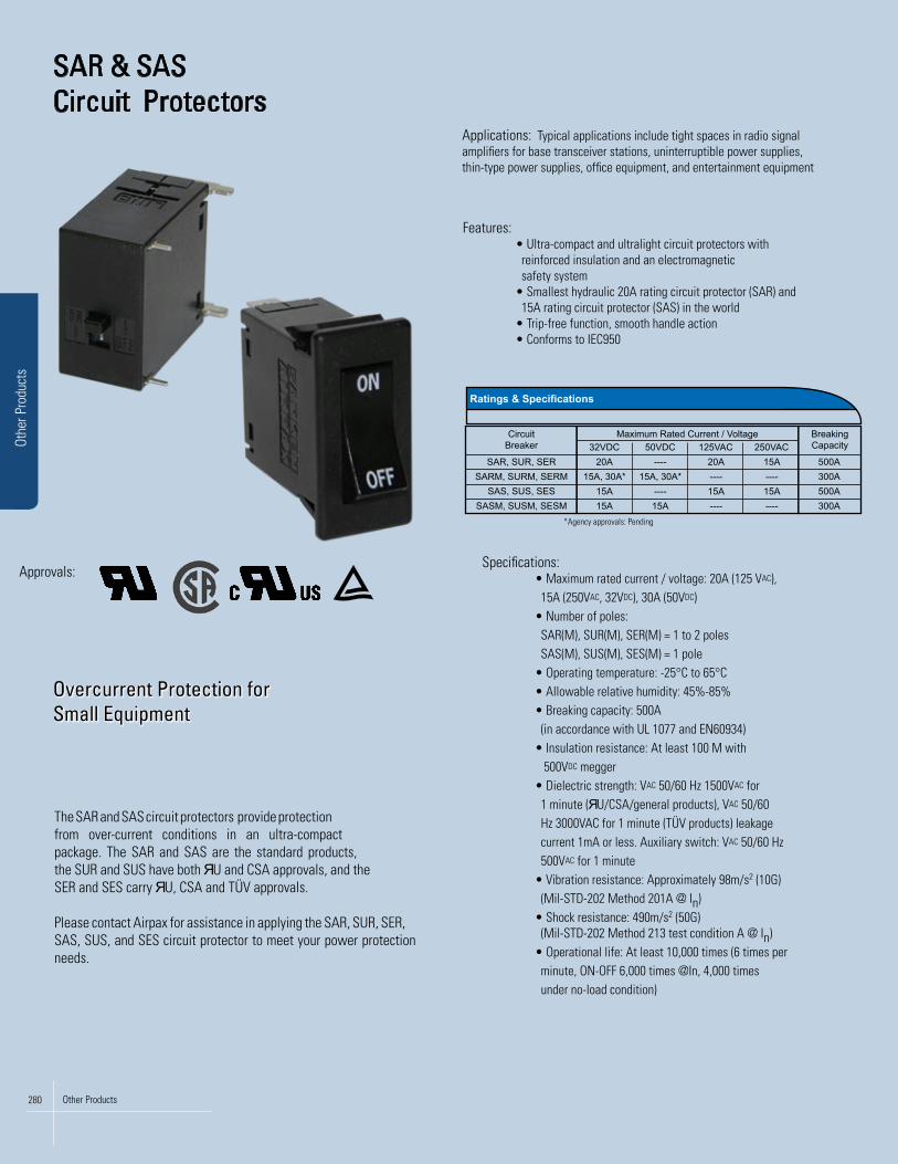
SAR & SAS Circuit Protectors
Overcurrent Protection for Small Equipment
Applications: Typical applications include tight spaces in radio signal amplifiers for base transceiver stations, uninterruptible power supplies, thin-type power supplies, office equipment, and entertainment equipment
Specifications: • Maximum rated current / voltage: 20A (125 VAC), 15A (250VAC, 32VDC), 30A (50VDC) • Number of poles: SAR(M), SUR(M), SER(M) = 1 to 2 poles SAS(M), SUS(M), SES(M) = 1 pole • Operating temperature: -25°C to 65°C • Allowable relative humidity: 45%-85% • Breaking capacity: 500A (in accordance with UL 1077 and EN60934) • Insulation resistance: At least 100 M with 500VDC megger • Dielectric strength: VAC 50/60 Hz 1500VAC for 1 minute ( U/CSA/general products), VAC 50/60 Hz 3000VAC for 1 minute (TÜV products) leakage current 1mA or less. Auxiliary switch: VAC 50/60 Hz 500VAC for 1 minute
• Vibration resistance: Approximately 98m/s2 (10G) (Mil-STD-202 Method 201A @ In)
• Shock resistance: 490m/s2 (50G) (Mil-STD-202 Method 213 test condition A @ In) • Operational life: At least 10,000 times (6 times per minute, ON-OFF 6,000 times @In, 4,000 times under no-load condition)
The SAR and SAS circuit protectors provide protection from over-current conditions in an ultra-compact package. The SAR and SAS are the standard products, the SUR and SUS have both U and CSA approvals, and the SER and SES carry U, CSA and TÜV approvals.
Please contact Airpax for assistance in applying the SAR, SUR, SER, SAS, SUS, and SES circuit protector to meet your power protection needs.
Features: • Ultra-compact and ultralight circuit protectors with reinforced insulation and an electromagnetic safety system • Smallest hydraulic 20A rating circuit protector (SAR) and 15A rating circuit protector (SAS) in the world • Trip-free function, smooth handle action • Conforms to IEC950
Approvals:
Ratings & Specifications
CircuitBreaker
BreakingCapacity
SAR, SUR, SER32VDC 50VDC 125VAC 250VAC
20A ---- 20A 15ASARM, SURM, SERM
Maximum Rated Current / Voltage
15A, 30A* 15A, 30A* ---- ----SAS, SUS, SES 15A ---- 15A 15A
SASM, SUSM, SESM 15A 15A ---- ----
500A300A500A300A
*Agency approvals: Pending
Other Products280
Othe
r Pro
duct
s

Guid
e to
Circ
uit P
rote
ctio
n
(–) LOAD
ON Marking(dimple)
.669(17)
1.283(32.6)
.094(2.4)
.413 max(10.5)
.244(6.2)
.748(19)
.394(10)
1.52
8(3
8.8)
1.260 (32)
.591(15)1.378
(35)
1.18
1 (3
0)
1.03
1(2
6.2)
2 x
.031
(0.8
)
.248
(6.3
)
(+) LINE
30º
2 x .031 (0.8)
1.035(26.3)
.669
(17)
.138
(3.5
)
1.161(29.5)
1.106(28.1)
.039 (1)
.138(3.5)
2 x .020 (0.5)
.110(2.8) 1.209
(30.7)
1.18
1 (3
0)
.118 (3)
ON
OFF
.177(4.5)
LINE
LOAD
.020(0.5) .236
(6).319(8.1)
SAS, SUS, SES, SASM, SUSM, SESM *Outline drawings show PCB mount. Dimensions = in (mm)
SAR, SUR, SER, SARM, SURM, SERM *Outline drawings show quick connect specifications. Dimensions = in (mm)
SAR - F - 1RE 1 - 51 - 10A - 52F - 5A - BWT - AC
Second Decision
Terminal type
2
Code
P
Description
F0.25” quick connect terminals
(SAR, SUR, SER, SARM, SURM, SERM only)
PCB - PC board terminals
Fourth Decision
Trip Delay
4
51
52
62
SP
61
Code Description
VDC mediumspeed
VDC low speed
VAC mediumspeed
VAC low speed
Relay type forvoltage trip
(SAR, SUR, SARM,SURM, only)
If an inertial wheel is required,add “F” to the end of the code.Example: 62F
If any switch type wasselected in the 3rd decision,do not choose a trip delay(4th decision)
Fifth Decision
Rated current*
5
0.1A
0.5A
1.0A
2.0A
3.0A
5.0A
7.5A
10.0A
15.0A
20.0A
25.0A
30.0A
250VAC
125VAC 0.1 to 20A
0.1 to 15A
0.1 to 15A
0.1 to 15A
0.1 to 30A (*4)
0.1 to 20A
0.1 to 15A
0.1 to 15A
----
0.1 to 1A
0.1 to 1A
0.1 to 1A
----
Main = 20A max
Main = 15A max
Main = 15A max
Main = 30A max (*4)50VDC
32VDC
SAR, SUR, SER, SARM, SURM, SERM*Rated current depends on the circuit type & circuit voltage
SAS, SUS, SES, SASM, SUSM, SESM
Code
Seventh Decision
Remarks
7
A, B, D
Code Description
PCB typeChose A, B, or D(SAR, SUR, SER,SARM, SURM,
SERM only)
ACSwitch type -
service circuit AC
DCSwitch type -
service circuit DCFirst Decision
Model
1
SAR
SUR
SER
SARM
SURM
SERM
SARM, SURM, SERM: note terminalshave porlarity, LINE connect to (+)
Code DescriptionGeneral Product
ЯU / CSA approved
ЯU / CSA / TÜV approved
General Product with magnet
cЯUus approved with magnet
cЯUus / TÜV approvedwith magnet
SAS
SUS
SES
SASM
SUSM
SESM
SASM, SUSM, SESM: note terminalshave porlarity, LINE connect to (+)
General Product
ЯU / CSA approved
ЯU / CSA / TÜV approved
General Product with magnet
ЯU / CSA approved with magnet
ЯU / CSA / TÜV approvedwith magnet
Third Decision
Circuit type
3
0Code Select 2 options****
Switch type
1 Series type
When the auxiliary switch or alarmswitch is a gold contact, “G” is addedto the symbol. For example “1REG”
0RESwitch type withauxiliary switch
1RESeries type withauxiliary switch
1RSSeries type with
alarm switch
3Parallel type
(SAR, SUR, SER, SARM,SURM, SERM only)
4Relay type
(SAR, SUR, SARM,SURM, only)
Sixth Decision
Handle marking (*1)
6
Code
BWT OnOff
DescriptionNo mark standard
Black handle
RWT Red handle
GUARD Handle Guard
BWY Black handle
RWY Red handle
On Off
On OffBWO Black handle
WBO White handle On Off
(han
dle
side
, lef
t)Po
le 1
(han
dle
side
, rig
ht)
Optio
nal P
ole
2 (*
2 , *
3)
(han
dle
side
, lef
t)Po
le 1
(han
dle
side
, rig
ht)
Optio
nal P
ole
2 (*
2)
CircuitVoltage
Switch type withauxiliary switch
Series type withalarm switch
Paralleltype
Relaytype
Use the options below for:SAR, SUR, SER,
SARM, SURM, SERM only
*3.) If the same specifications are required in the 4th and 5th decision for each pole in a 2-pole device (example, both poles require 51-10A), do not enter a Optional Pole 2 entry into the 4th and 5th decision.
Example: SAR-F-1RE 1 - 51 - 10A both poles need 51-10A
*1.) This decision only applies to: SAR, SUR, SER, SARM, SURM, SERM
Disregard sixth decision for: SAS, SUS, SES, SASM, SUSM, SESM
*2.) 2-pole options are only available for: SAR, SUR, SER, SARM, SURM, SERM
Disregard the pole 2 option for: SAS, SUS, SES, SASM, SUSM, SESM
*4.) SARM - 50VDC, 30A max SURM/SERM - 50VDC, 15A max
Oth
er P
rodu
cts
Other Products 281

Othe
r Pro
duct
s
Other Products282
QAS, QAL, QFS, QFLQuick-Action Fuses
Overcurrent Protection forSemiconductor Elements and Cables
Applications: Typical applications include inverters, arc welders, rectifiers, CNC equipment, battery circuits, and other protective applications.
Features: • L-type terminal construction for easy installation • U, c Uus, and TÜV approved products available • Large breaking capacity (100kA) • Low I2t value, semiconductor protection balance can be easily obtained • Compact and lightweight • Resistant to repetitive currents • Excellent current-limiting characteristics • Low power loss
Specifications: • Rated voltage: 250-600VAC; 300-500VDC
• Rated current: 10A-300A • Breaking capacity: 100kA at 250VAC and 600 VAC; 10kA at 300 VDC and 500 VDC
• Power loss: 1W-43W • Connecting bar: 0.016-0.310in2 (10-200mm2) • I2t (A2S)X103: Fusing = .009-14; Operating at 250VAC = .04-102; Operating at 600VAC = .6-175
• Approvals:
The QAS, QAL, QFS, QFL product lines feature L-type terminals and carry a rated voltage of up to 600 VAC and 500 VDC, 300A max, 100K AIC. They feature a high current-limiting effect and superior quick-action fusing performance, excellent arc-suppressing performance, and reliable breaking action. Because of their low power loss, they save energy and also feature low surge voltage at the breaking point. Superior non-degradation characteristics make it ideal for motors subject to extreme load variations.
Indicator Fuse
Microswitchwith Housing
Increase uptime bypinpointing open fuseswith this instant visualidentification.
Couple the indicator fusewith a microswitch tocreate an integratedsystem which providesa signal to a panel orCPU to inform atechnician about whichfuse is blown.
Fuse Holder
Increase mountingoptions by incorporatinga fuse holder into yoursystem.
Model
20 to 100 10kA / 10kA250VAC / 300VDC
Options
QAS25U-
75 to 300 250VAC / 300VDCQAL25U-
RatedCurrent
(A)
RatedVoltage
(V)
BreakingCapacity
(VAC / VDC)
10kA / 10kA
20 to 75 600VAC / 500VDCQAS60U- 100kA / 10kA
10 to 100 250VAC (cЯUus, TÜV)400VDC (cЯUus)
QFS25U- 10kA / 10kA
75 to 300 250VAC (cЯUus, TÜV)400VDC (cЯUus)
QFL25U- 10kA / 10kA
100 to 300 600VAC / 500VDCQAL60U- 100kA / 10kA
* U, UL Recognized Component:UL file # E174284 (250VAC/300VDC, 600VAC/500VDC)
*c Uus, UL Recognized Component, U.S.A. & Canada:UL file # E174284 (250VAC/400VDC)
*TÜV Approved:TÜV file # J2150262, J2150268, J2150270, J2150271 (250VAC)
*These approvals are options available in this product family, general products do not carry these approvals. Review the Airpax catalog and website for further
information on part numbers and product specifications for these approvals.

Model
Ratings & Specifications
QAS25-75 (S)
QAS25-100 (S)
QAL25-75 (S)
QAL25-100 (S)
QAL25-150 (S)
QAL25-200 (S)
QAL25-300 (S)
(W) Pow
er Loss
Connecting Bar
I²t(A²s)x10³
7.0
10.0
8.0
10.0
15.0
20.0
30.0
QFS25-10 (S)1.0
QFS25-20 (S)2.1
QFS25-30 (S)3.8
QFS25-50 (S)5.9
QFS25-75 (S)8.0
QFS25-100 (S)11.6
QFL25-75 (S)7.7
QFL25-100 (S)10.6
QFL25-150 (S)17.6
QFL25-200 (S)22.5
QFL25-300 (S)35.4
RatedVoltage
250 VAC
300 VDC
250 VAC
400 VDC
600 VAC
500 VDC
QAS60-20 (S)3.0
QAS60-30 (S)5.0
QAS60-50 (S)10.0
QAS60-75 (S)17.0
QAL60-100 (S)20.0
QAL60-150 (S)26.0
QAL60-200 (S)32.0
QAL60-250 (S)38.0
QAL60-300 (S)
RatedCurrent
(A)
75
10075
100
150
200
3001020305075
10075
100
150
200
300 20305075
100
150
200
250
30043.0
Fusing
0.49
0.87
0.49
0.87
1.9
3.5
8.9
0.009
0.035
0.055
0.18
0.49
0.88
0.49
0.88
1.98
3.51
8.99
0.030
0.054
0.17
0.47
0.87
2.3
4.4
7.9
14.0
Operatingat V
AC
5.92
9.8
5.9
9.8
19.0
35.0
102.0
0.04
0.17
0.35
0.85
2.3
4.0
2.3
4.0
9.5
17.0
38.0
0.6
1.2
2.8
6.0
14.0
38.0
84.0
135.0
175.0
*6
*5*2, 7
*3,4,8
*1
BreakingCapacity
10kA at250V
AC
(ЯU)
100kA at250 V
AC
10kA at300 V
DC
100kA at600 V
AC
10kA at500 V
DC
10kA at250V
AC
(cЯUus)
(TÜV)
100kA at250 V
AC
10kA at400 V
DC
(cЯUus)*1 *1
QAS25-20 (S)2.0
200.03
0.82
QAS25-30 (S)3.0
300.054
1.5
QAS25-50 (S)5.0
500.17
2.9
3245324575
160
20010
14.4
264560806080
125
200
300 1212243232
100
160
200
200
mm
²121224
0.019
0.019
0.037
0.050
0.070
0.050
0.070
0.116
0.248
0.310
0.016
0.022
0.040
0.070
0.093
0.124
0.093
0.124
0.194
0.310
0.465
0.019
0.019
0.037
0.050
0.050
0.155
0.248
0.310
0.310
in²M
odel
External dimensions: in (m
m)
External DimensionsA
BC
DE
FG
TW
JK
L
Weight:oz
(gram)
Mounting Hole,
Bolt Size Limit
QFS25-10 (S)
QAS25-20 (S)QFS25-20 (S)QAS25-30 (S)QFS25-30 (S)QAS25-50 (S)QFS25-50 (S)QAS25-75 (S)QFS25-75 (S)
QAL25-75 (S)QFL25-75 (S)
QAS25-100 (S)QFS25-100 (S)
QAL25-100 (S)QFL25-100 (S)QAL25-150 (S)QFL25-150 (S)
QAL25-200 (S)QFL25-200 (S)
QAL25-300 (S)QFL25-300 (S)
QAS60-20 (S)
QAS60-30 (S)
QAS60-50 (S)
QAS60-75 (S)
QAS60-100 (S)
QAS60-150 (S)
QAS60-200 (S)
QAS60-250 (S)
QAS60-300 (S)
(56)(42)
(26)(18.5)
(17.5)(8.5)
(6.5)(2)
(12)(26)
(17.5)(22)
(30)(? M
6)
2.2051.654
1.0240.728
0.6890.335
0.2560.079
0.4721.024
0.6890.866
1.058? 1/4 - 20
(80)(58)
(29)(31)
(27)(11)
(9)(3)
(20)(35)
(21.5)(30)
(100)(? M
9)
3.1502.283
1.1421.220
1.0630.433
0.3540.118
0.7871.378
0.8461.181
3.527? 5/16 - 18
(70)(56)
(40)(18.5)
(17.5)(8.5)
(6.5)(2)
(12)(26)
(17.5)(22)
(36)(? M
6)
2.7562.205
1.5750.728
0.6890.335
0.2560.079
0.4721.024
0.6890.866
1.270? 1/4 - 20
(99)(74)
(43)(40.5)
(37)(13)
(11)(3)
(30)(45)
(26.5)(34.5)
(220)(? M
11)
3.8982.913
1.6931.594
1.4970.512
0.4330.118
1.1811.771
1.0431.358
7.760? 7/16 - 14
(85)(60)
(29)(34.5)
(31)(13)
(11)(3)
(25)(39)
(23.5)(31.5)
(135)(? M
11)
3.3462.362
1.1421.358
1.2200.512
0.4330.118
0.9841.535
0.9251.240
4.762? 7/16 - 14
(85)(60)
(29)(40.5)
(37)(13)
(11)(3)
(30)(45)
(26.5)(34.5)
(185)(? M
11)
3.3462.362
1.1421.594
1.4570.512
0.4330.118
1.1811.771
1.0431.358
6.526? 7/16 - 14
(93)(71)
(42)(31.5)
(27)(11)
(9)(3)
(20)(35)
(21.5)(30)
(115)(? M
9)3.661
2.7951.654
1.2401.063
0.4330.354
0.1180.787
1.3780.846
1.1814.056
? 5/16 - 18
(97)(72)
(41)(34.5)
(31)(13)
(11)(3)
(25)(39)
(23.5)(31.5)
(150)(? M
11)3.819
2.8351.614
1.3581.220
0.5120.433
0.1180.984
1.5350.925
1.2405.291
? 7/16 - 14
ABG
DL
F
(50)1.969
(6.5)
(3)
W
(Ø 7)Ø 0.276
J
K
T
E
C
0.118
0.256
Before
Fusing:
After
Fusing:
First Decision
Model
QA
S25 - -
1
QA
S25
General
Product
(no approvals)
QA
L25Q
AS
60Q
AL60
QFS
25Q
FL25Q
AS
25UQ
AL25U
QA
S60U
QA
L60UQ
FS25U
QFL25U
QFS
25U- -T
QFL25U
- -T
Second Decision
Rated current (A
) 2
Input a value from 10 to 300
Use reference table
“Ratings &
Specifications”
Third Decision
Accessories
3No entry
Fuse unit only
Equipped w
ith fusing indicator fuse
Equipped w
ith fusing indicator fuse and microsw
itch w
ith housing (silver contacts, solder-on terminals)***
Equipped w
ith fusing indicator fuse and microsw
itch w
ith housing (gold contacts, quick-connect #110 terminals)
Equipped w
ith fusing indicator fuse and smaller m
icroswitch
with housing (silver contacts, solder-on term
inals)***
Equipped w
ith fusing indicator fuse and smaller m
icroswitch
with housing (gold contacts, solder-on term
inals)***
cЯU
us, TÜV
approved product, available only on QFS
25U
and QFL25U
. No indicator fuse or m
icroswitch options.
S
S-M
1
S-M
2
S-M
3
S-M
4
T
*1. Time constant is 4m
s max.
*2. Calculated value.
*3. Actual measured value at
conventional current of 250VAC at 100kA (r.m
.s.) and short-circuit pow
er factor of 14%
.
*4. Indicates actual measured
value at conventional current of 600VAC at 100kA (r.m
.s.) and short-circuit pow
er factor of 7%
.
*5. QAS / QAL / QFS / QFL - Specifications of th e indicator fuse are the sam
e.
*6. Max value at rated current.
*7. Radiation is not considered in this calculated value.
*8. Max value at conventional
current of 250VAC at 100kA (r.m
.s.) and short-circuit pow
er factor of 16%.
( S ) : Indicator fuse option available, place an S at the end of the PN
. Example
QAS60-300 becomes QAS60-300S
Outline drawings show
fuse with
indicator fuse specifications
***Review the Airpax full catalog
and website for further info
on PNs and options available
Oth
er P
rodu
cts
Other Products 283

HVS & SARPVCompact Switchesfor Solar PowerApplications
High DC Voltage,Compact Disconnect Switches
Application: Inverters for a solar power generator typically require the use of a large disconnect switch to handle the high DC voltages associated with solar panels. Introducing the HVS and SARPV high voltage disconnect switches, each with a compact design allowing for expanded design options. This smaller design provides the means for overall system size reduction and eliminates the need for a large separate control enclosure. In addition, the optional remote disconnect configuration and auxiliary switch allows the system controller to be located in an unobstructed location.
Specifications: • Maximum rated current / voltage: HVS = 30A / 300VDC (open voltage 450VDC) SARPV = 10A / 300VDC (open voltage 450VDC) • Number of poles: HVS = 2 to 3 poles SARPV = 2 poles • Ambient operating temperature: HVS = -25°C to +70°C SARPV = -25°C to +65°C • Operational life: >5000 cycles @ 2x per minute @ In • Insulation resistance: > 100M @ 500VDC
• Dielectric strength: VAC 50 / 60 Hz, 2000V for 1 minute leakage current 1mA or less. Auxiliary switch: VAC 50 / 60 Hz, 500V for 1 minute between contacts
• Auxiliary switch ratings (resistive load): Silver contacts: 3A / 125VAC, 2A / 30VDC
Gold contacts: 0.05A / 30VDC
• Vibration resistance: Approximately 98m/s2 (10G) (Mil-STD-202 Method 201A test condition A @ In)
• Shock resistance: 490m/s2 (50G) (Mil-STD-202 Method 213B test condition A @ In)
• Coil resistance (DCR), 24VDC coil: 157 ± 25% @ 25°C
• Agency approvals: Pending
Airpax, a global leader in the supply of power protection products, has expanded its offering to include two new high voltage switch products for the solar power market. The HVS and SARPV switches provide an ultra-compact means of disconnecting higher DC voltages typically seen in solar power generation systems. In addition, for communicating with a central panel or controller, both are available with remote signal disconnect and auxiliary switch option.
Othe
r Pro
duct
s
Other Products284

(–) LOAD
(+) LINE
.177(4.5)
1.854(47.1)2.126 (54)
.748(19) 1.280 max
(32.5)
.630(16)
POLE 1
POLE 2
4 x M3 depth: 4 x M3 depth:4 x Ø .157 (4)
.630(16)
.654 + .008(16.6 + .2)
1.53
5 (3
9)
.622
(15.
8).5
04(1
2.8)
OFF
.256(6.5)
43º
1.24
4(3
1.6)
1.94
9(4
9.5)
1.53
5 (3
9) 1.51
2(3
8.4)
.219
(5.5
)
.591(15)
.157 (4)
.504(12.8)
.236 max (6)
Mounting Tolerance± .008(± 0.2)
(–) LOAD
(+) LINE.091(2.3)
.433 max(11)
1.283(32.6)
.094(2.4) .394
(10)
1.378(35)
1.260(32) PCB terminal
.591(15)
NC
NO
.488(12.4).154
(3.9)
C
.244(6.2) ON Marking
(dimple)30º
.504
(12.
8)
1.18
1 (3
0)
1.03
1(2
6.2)
1.52
8(3
8.8)
.969
(24.
6)
.197 (5)
.047
(1.2
).2
48(6
.3)
2 x .031 (0.8)
3 x .035 (0.9)
SARPV *Outline drawings show: optional auxiliary switch, F terminal, and P terminal dimensions. Dimensions = in (mm)
HVS *Outline drawings show HVS-40 specifications. Dimensions = in (mm)
HVS - 40 - SP - DC24V - MFirst Decision
Model
1
HVSCode
HVSH
DescriptionSingle handle
H-handle
Fourth Decision
Trip Voltage
4
DC24VCode Description
24VDC
Fifth Decision
Remarks
5
MCode Description
Wiring screw attached
Third Decision
Tripping characteristics
3
SPCode Description
Delay SP
Second Decision
Circuit type
2
0Code
4
Select 2 or 3 options***Switch typeRelay type
0RE Switch type with auxiliary switch (silver contacts)0REG Switch type with auxiliary switch (gold contacts)
1. Available trip voltage is only 24 VDC, consult factory for alternative trip ratings2. Polarity designation: Connect LINE-side terminal to (+) pole
Third and fourth decision must be left blankwhen the second decision is not relay type
Fifth decision must be left blank when customerdoes not require screws be attached
SARPV - F - 40 - SP - DC24V - -
Second Decision
Terminal type
2
FCode
P
DescriptionQuick-connect
PCB
Fourth Decision
Trip characteristics
4
SPCode Description
Delay SP
Fifth Decision
Trip Voltage
5
DC24VCode Description
24VDC
Seventh Decision
Remarks
7
DCode Description
PCB type
First Decision
Model
1
SARPVCode Description
SARPV
Third Decision
Circuit type
3
0Code
4
Select 2 options****Switch typeRelay type
0RESwitch type withauxiliary switch(silver contacts)
0REGSwitch type withauxiliary switch(gold contacts)
Sixth Decision
Handle marking
6
Code
BWT OnOff
DescriptionNo mark standard
Black handle
RWT Red handle
Guard Handle Guard
BWY Black handle
RWY Red handle
OnOff
**** SARPV can be only be a 2-pole breaker Select circuit type for each pole (second decision):First entry: Pole 1, LH (left-hand) sideSecond entry: Pole 2. RH (right-hand) side
EXAMPLE: HVS-40HVS, Pole 1 (LH) Relay type, Pole 2 (RH) Switch type, no 3-pole
*** HVS, HVSH can be either a 2-pole or a 3-pole breaker
Select circuit type for each pole (second decision):First entry: Pole 1, LH (left-hand) sideSecond entry: Pole 2. RH (right-hand) side for 2-pole, center for optional 3-poleOptional third entry: Pole 3 RH (right-hand) side for 3-pole, leave blank for 2-pole
EXAMPLE: SARPV-F-40SARPV, quick-connects, Pole 1 (LH) Relay type, Pole 2 (RH) Switch type
Fourth and fifth decision must be left blankwhen the third decision is not relay type
Seventh decision must be left blank when thesecond decision is not PCB type
Oth
er P
rodu
cts
285