overture series vinyl folding patio door system · overture series vinyl folding ... 4 supplies...
TRANSCRIPT
For warranty issues and concerns, please contact the installing dealer or window manufacturer. Proper assembly, installation and maintenance are essential to achieve the benefits your Royal Patio Door product has to offer. Please read and follow this instruction guide completely. You may direct any questions about this or other products to your local Royal Patio Door dealer, found in the Yellow Pages under "Windows" or call Toll Free 1.888.339.9085. Thank you for choosing Royal Patio Door.
Every assembly and installation is different (windloads, structural support, etc.) Royal Patio Doors strongly recommends consultation with a Royal Patio Doors supplier or an experienced contractor, architect, or structural engineer prior to the assembly and installation of any Royal Patio Doors product. Royal Patio Doors has no responsibility with regard to the post-manufactured assembly and installation of Royal Patio Doors products.
Follow manufacturers' instructions for hand or power tools. Always wear safety glasses. Failure to do so may result in injury and/or product damage.
Windows and doors can be heavy. Use safe lifting techniques and a reasonable number of people with enough strength to lift, carry and install window & door products to avoid injury and/or product damage.
• Unit must be properly flashed and sealed with silicone for protection against water and air infiltration.• Do not apply any type of film to glass.
Installation GuidePatio DoorsROYAL
INSTALLATION GUIDEOVERTURE Series Vinyl Folding Patio Door System
Installer: Please leave this guide with the building owner to file for future reference.
Important Safety, Assembly and Installation Information
WARNING! WARNING!
CAUTION!
www.royalbuildingproducts.com 1.888.339.90851
OPDIG 001-2011-RB 4233 R12
Installation GuidePatio DoorsROYAL
GENERAL NOTES
www.royalbuildingproducts.com 1.888.339.90852
The attached instructions details the step by step process to assembling and recommended installation guide to the referenced Royal Patio Door - Overture Folding Door System. Not all information, including cross-section details, is included but is available from Royal Patio Doors upon request.
Royal Patio Doors is only a material supplier of specific folding panel systems as shown in the attached instructions. It does not install, design, or engineer any conditions surrounding the opening to which Royal Patio Door systems are installed.
It is the sole responsibility of the Buyer, architect, building owner, contractor, and/or consumer (hereinafter referred to as the “customer”) to ensure that the products and options selected conform to all applicable codes and regulations, including federal, provincial, state, and local building codes governing the use of glazed windows, doors, storefronts, and/or partitions.
Proper installation, operation, and maintenance of the products are essential to ensure lasting performance. Written installation, operation, and maintenance instructions are provided to all customers. It is essential that these instructions are read and followed. It is highly recommended that an experienced installer of Royal Patio Door products be used for such relevant aspects of the installation. Installation, including but not limited to method of attachment, fastener selection and completion of appropriate waterproofing, flashing, and application of sealant or caulk around the perimeter of the opening is the sole responsibility of the customer.
The structural integrity of the Header and/or overhead support for the opening, to be provided and installed by others, is critical for proper performance and operation. The header, surrounding walls, and floor must also be able to support any lateral loads. If unsure, please contact a structural engineer, architect or building professional for further assistance.
Royal Patio Door systems with different configurations have been tested with varying degrees of performance results. Not all systems or possibilities have been tested. See information available in Royal Patio Door literature and our website. It is the sole responsibility of the customer to determine the required level of performance, including project design wind load requirements, for the specific location and site conditions and to determine the appropriate Royal Patio Door system, size and sill necessary.
All sizing found within these instructions are in Imperial dimensions and rounded to the nearest 1/8”. Drawings shown are subject to change without notice.
www.royalbuildingproducts.com3
TABLE OF CONTENTS
Installation GuidePatio DoorsROYAL
General Warnings, Cautions and Notices . . . . . . . . . . . . . . . . . . . . . . . . . . . . . . . . . . . . . . . . . . . . . . . . . . . . . . . . . . . 2Parts Included . . . . . . . . . . . . . . . . . . . . . . . . . . . . . . . . . . . . . . . . . . . . . . . . . . . . . . . . . . . . . . . . . . . . . . . . . . . . . . . 4Supplies Recommended . . . . . . . . . . . . . . . . . . . . . . . . . . . . . . . . . . . . . . . . . . . . . . . . . . . . . . . . . . . . . . . . . . . . . . . . 4Tools Recommended. . . . . . . . . . . . . . . . . . . . . . . . . . . . . . . . . . . . . . . . . . . . . . . . . . . . . . . . . . . . . . . . . . . . . . . . . . . 4Screw Pack Contents . . . . . . . . . . . . . . . . . . . . . . . . . . . . . . . . . . . . . . . . . . . . . . . . . . . . . . . . . . . . . . . . . . . . . . . . . . 4Glass Warnings and Cautions. . . . . . . . . . . . . . . . . . . . . . . . . . . . . . . . . . . . . . . . . . . . . . . . . . . . . . . . . . . . . . . . . . . . 5Film Removal Warnings . . . . . . . . . . . . . . . . . . . . . . . . . . . . . . . . . . . . . . . . . . . . . . . . . . . . . . . . . . . . . . . . . . . . . . . . 5Cleaning Cautions . . . . . . . . . . . . . . . . . . . . . . . . . . . . . . . . . . . . . . . . . . . . . . . . . . . . . . . . . . . . . . . . . . . . . . . . . . . . 5Maintenance Guide . . . . . . . . . . . . . . . . . . . . . . . . . . . . . . . . . . . . . . . . . . . . . . . . . . . . . . . . . . . . . . . . . . . . . . . . . . . 6Hardware Identification . . . . . . . . . . . . . . . . . . . . . . . . . . . . . . . . . . . . . . . . . . . . . . . . . . . . . . . . . . . . . . . . . . . . . . . . 8Hinge Identification and Quantities . . . . . . . . . . . . . . . . . . . . . . . . . . . . . . . . . . . . . . . . . . . . . . . . . . . . . . . . . . . . . . . 9Frame Assembly . . . . . . . . . . . . . . . . . . . . . . . . . . . . . . . . . . . . . . . . . . . . . . . . . . . . . . . . . . . . . . . . . . . . . . . . . . . . . . 9Prepare Rough Opening (recommended) . . . . . . . . . . . . . . . . . . . . . . . . . . . . . . . . . . . . . . . . . . . . . . . . . . . . . . . . . . 10Anchor Location . . . . . . . . . . . . . . . . . . . . . . . . . . . . . . . . . . . . . . . . . . . . . . . . . . . . . . . . . . . . . . . . . . . . . . . . . . . . . 13Optional Low Profile Sill Installation . . . . . . . . . . . . . . . . . . . . . . . . . . . . . . . . . . . . . . . . . . . . . . . . . . . . . . . . . . . . . 14Install Frame . . . . . . . . . . . . . . . . . . . . . . . . . . . . . . . . . . . . . . . . . . . . . . . . . . . . . . . . . . . . . . . . . . . . . . . . . . . . . . . 16Install Hardware . . . . . . . . . . . . . . . . . . . . . . . . . . . . . . . . . . . . . . . . . . . . . . . . . . . . . . . . . . . . . . . . . . . . . . . . . . . . . 20Install Door Panels . . . . . . . . . . . . . . . . . . . . . . . . . . . . . . . . . . . . . . . . . . . . . . . . . . . . . . . . . . . . . . . . . . . . . . . . . . . 23Install Keeper, Handle and Cylinder . . . . . . . . . . . . . . . . . . . . . . . . . . . . . . . . . . . . . . . . . . . . . . . . . . . . . . . . . . . . . . 26Check Clearance and Operation. . . . . . . . . . . . . . . . . . . . . . . . . . . . . . . . . . . . . . . . . . . . . . . . . . . . . . . . . . . . . . . . . 27Apply Silicone and Weather Strip Adapter. . . . . . . . . . . . . . . . . . . . . . . . . . . . . . . . . . . . . . . . . . . . . . . . . . . . . . . . . 28Insulate Unit. . . . . . . . . . . . . . . . . . . . . . . . . . . . . . . . . . . . . . . . . . . . . . . . . . . . . . . . . . . . . . . . . . . . . . . . . . . . . . . . 30
Folding Door Configurations . . . . . . . . . . . . . . . . . . . . . . . . . . . . . . . . . . . . . . . . . . . . . . . . . . . . . . . . . . . . . . . . . . . 33
Fasten Bottom Sweep to Sash . . . . . . . . . . . . . . . . . . . . . . . . . . . . . . . . . . . . . . . . . . . . . . . . . . . . . . . . . . . . . . . . . . 31Apply Hinge Gaskets. . . . . . . . . . . . . . . . . . . . . . . . . . . . . . . . . . . . . . . . . . . . . . . . . . . . . . . . . . . . . . . . . . . . . . . . . . 32
1.888.339.9085
Rough opening header must not deflect more than 1/16" when carrying the weight of door panels. Door header must carry weight of door panels and all loads effecting opening. Too much deflection will affect product performance.
Metal fasteners and other hardware components may corrode when exposed to preservative treated and fire-retardent treated lumber. Obtain and use the appropriate metal fasteners and hardware as called out by the installation guide to fasten unit to any rough opening made from pressure and fire-retardant treated lumber. Failure to use the appropriate materials for the installation may cause a failure resulting in injury, property or product damage.
Due to the complicated nature of this installation, Royal Patio Doors strongly recommends consulting with an installation professional before attempting to install this product.
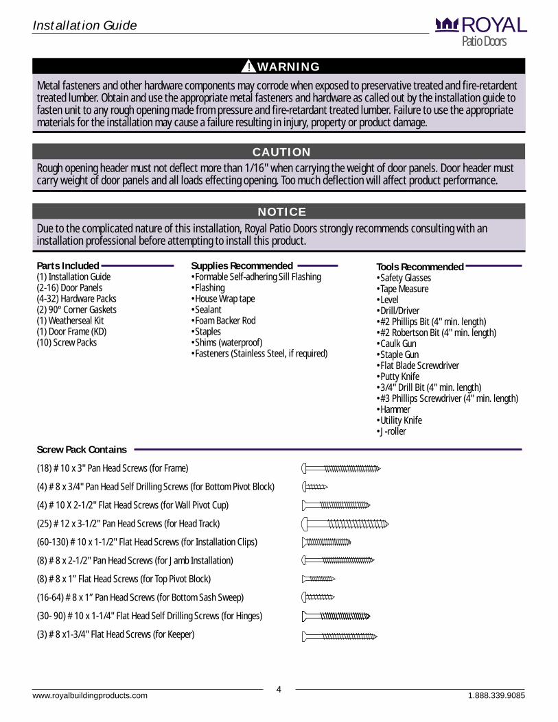
Parts Included(1) Installation Guide(2-16) Door Panels(4-32) Hardware Packs(2) 90º Corner Gaskets(1) Weatherseal Kit(1) Door Frame (KD)(10) Screw Packs
Supplies Recommended•Formable Self-adhering Sill Flashing•Flashing•House Wrap tape•Sealant•Foam Backer Rod•Staples•Shims (waterproof)•Fasteners (Stainless Steel, if required)
Tools Recommended•Safety Glasses•Tape Measure•Level•Drill/Driver•#2 Phillips Bit (4" min. length)•#2 Robertson Bit (4" min. length)•Caulk Gun•Staple Gun•Flat Blade Screwdriver•Putty Knife•3/4" Drill Bit (4" min. length)•#3 Phillips Screwdriver (4" min. length)•Hammer•Utility Knife•J-roller
www.royalbuildingproducts.com4
WARNING!
CAUTION
NOTICE
Installation GuidePatio DoorsROYAL
1.888.339.9085
(18) # 10 x 3" Pan Head Screws (for Frame)
(4) # 8 x 3/4" Pan Head Self Drilling Screws (for Bottom Pivot Block)
(4) # 10 X 2-1/2" Flat Head Screws (for Wall Pivot Cup)
(25) # 12 x 3-1/2" Pan Head Screws (for Head Track)
(60-130) # 10 x 1-1/2" Flat Head Screws (for Installation Clips)
(8) # 8 x 2-1/2" Pan Head Screws (for Jamb Installation)
(8) # 8 x 1” Flat Head Screws (for Top Pivot Block)
(16-64) # 8 x 1” Pan Head Screws (for Bottom Sash Sweep)
(30- 90) # 10 x 1-1/4" Flat Head Self Drilling Screws (for Hinges)
(3) # 8 x1-3/4" Flat Head Screws (for Keeper)
Screw Pack Contains
Static created when removing film can ignite flammable materials or cause a shock.
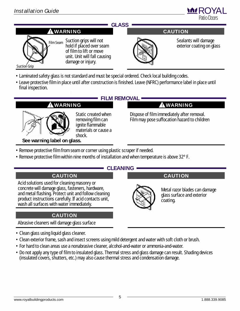
• Laminated safety glass is not standard and must be special ordered. Check local building codes.• Leave protective film in place until after construction is finished. Leave (NFRC) performance label in place until
final inspection.
• Remove protective film from seam or corner using plastic scraper if needed.• Remove protective film within nine months of installation and when temperature is above 32º F.
www.royalbuildingproducts.com5
WARNING!
Suction grips will not hold if placed over seam of film to lift or move unit. Unit will fall causing damage or injury.
Film Seam
Suction Grip
GLASSCAUTION
Sealants will damage exterior coating on glass
WARNING!
FILM REMOVAL
See warning label on glass.
Dispose of film immediately after removal. Film may pose suffocation hazard to children
WARNING!
Installation GuidePatio DoorsROYAL
CAUTIONCLEANING
CAUTION
Acid solutions used for cleaning masonry or concrete will damage glass, fasteners, hardware, and metal flashing. Protect unit and follow cleaning product instructions carefully. If acid contacts unit, wash all surfaces with water immediately.
• Clean glass using liquid glass cleaner.• Clean exterior frame, sash and insect screens using mild detergent and water with soft cloth or brush.• For hard to clean areas use a nonabrasive cleaner, alcohol-and-water or ammonia-and-water.• Do not apply any type of film to insulated glass. Thermal stress and glass damage can result. Shading devices
(insulated covers, shutters, etc.) may also cause thermal stress and condensation damage.
Abrasive cleaners will damage glass surface
CAUTION
Metal razor blades can damage glass surface and exterior coating.
1.888.339.9085
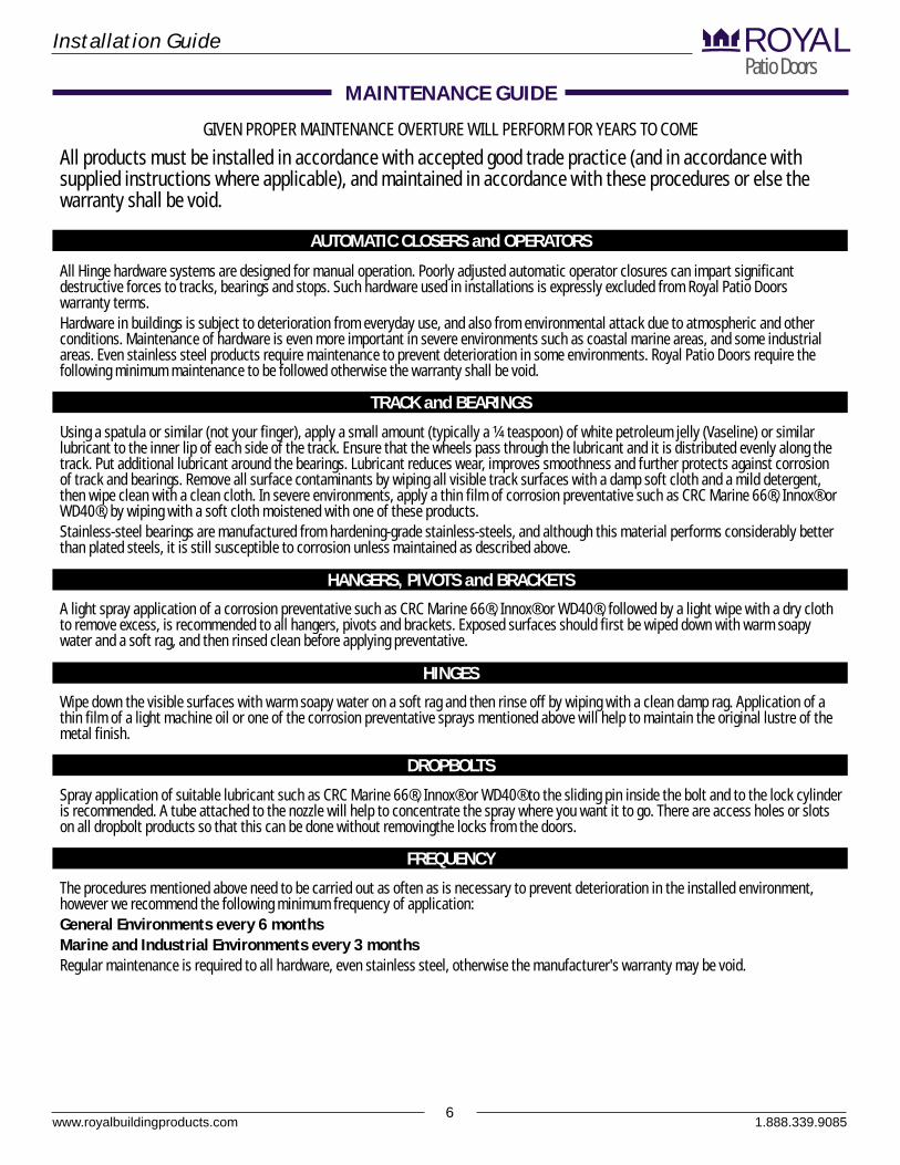
GIVEN PROPER MAINTENANCE OVERTURE WILL PERFORM FOR YEARS TO COME
All products must be installed in accordance with accepted good trade practice (and in accordance with supplied instructions where applicable), and maintained in accordance with these procedures or else the warranty shall be void.
All Hinge hardware systems are designed for manual operation. Poorly adjusted automatic operator closures can impart significant destructive forces to tracks, bearings and stops. Such hardware used in installations is expressly excluded from Royal Patio Doors warranty terms.Hardware in buildings is subject to deterioration from everyday use, and also from environmental attack due to atmospheric and other conditions. Maintenance of hardware is even more important in severe environments such as coastal marine areas, and some industrial areas. Even stainless steel products require maintenance to prevent deterioration in some environments. Royal Patio Doors require the following minimum maintenance to be followed otherwise the warranty shall be void.
Using a spatula or similar (not your finger), apply a small amount (typically a ¼ teaspoon) of white petroleum jelly (Vaseline) or similar lubricant to the inner lip of each side of the track. Ensure that the wheels pass through the lubricant and it is distributed evenly along the track. Put additional lubricant around the bearings. Lubricant reduces wear, improves smoothness and further protects against corrosion of track and bearings. Remove all surface contaminants by wiping all visible track surfaces with a damp soft cloth and a mild detergent, then wipe clean with a clean cloth. In severe environments, apply a thin film of corrosion preventative such as CRC Marine 66®, Innox® or WD40®, by wiping with a soft cloth moistened with one of these products.Stainless-steel bearings are manufactured from hardening-grade stainless-steels, and although this material performs considerably better than plated steels, it is still susceptible to corrosion unless maintained as described above.
A light spray application of a corrosion preventative such as CRC Marine 66®, Innox® or WD40®, followed by a light wipe with a dry cloth to remove excess, is recommended to all hangers, pivots and brackets. Exposed surfaces should first be wiped down with warm soapy water and a soft rag, and then rinsed clean before applying preventative.
Wipe down the visible surfaces with warm soapy water on a soft rag and then rinse off by wiping with a clean damp rag. Application of a thin film of a light machine oil or one of the corrosion preventative sprays mentioned above will help to maintain the original lustre of the metal finish.
Spray application of suitable lubricant such as CRC Marine 66®, Innox® or WD40® to the sliding pin inside the bolt and to the lock cylinder is recommended. A tube attached to the nozzle will help to concentrate the spray where you want it to go. There are access holes or slots on all dropbolt products so that this can be done without removingthe locks from the doors.
The procedures mentioned above need to be carried out as often as is necessary to prevent deterioration in the installed environment, however we recommend the following minimum frequency of application:General Environments every 6 months Marine and Industrial Environments every 3 monthsRegular maintenance is required to all hardware, even stainless steel, otherwise the manufacturer's warranty may be void.
TRACK and BEARINGS
AUTOMATIC CLOSERS and OPERATORS
HANGERS, PIVOTS and BRACKETS
HINGES
DROPBOLTS
FREQUENCY
www.royalbuildingproducts.com6
MAINTENANCE GUIDE
Installation GuidePatio DoorsROYAL
1.888.339.9085
As a general rule, cleaning should take place at least every six months. In areas where environmental deposits are more prevalent, such as beach-front houses and industrial or geothermal areas, then cleaning should be carried out on a more frequent basis i.e. every two to three months.Three Steps to Cleaning Your Powdercoated HardwareStep 1. Remove loose deposits with a wet sponge rather than risk scratching the surface with dry dusting.Step 2. Using a soft brush/cloth and soap or mild household detergent in warm water, clean the surface to remove dust, salt and other
deposits.Step 3. Always rinse with fresh water after cleaning to remove any remaining detergent.Precautions for Powdercoated Hardware
• NEVER use aggressive solvent cleaners on the product i.e. thinners and petrol.• AVOID the use of any solvents near joints or plastic components.• NEVER use anything abrasive i.e. steel wool, scrapers, scouring liquids or powders.• Ensure that the solvent is thoroughly rinsed from the product surface.
Maintaining Your Plated HardwareSpecial care needs to be taken to maintain plated surfaces.
• CLEAN with a soft damp cloth or dry duster.• NEVER use abrasive cleaners, scourers or rough cloth that may damage or scratch the plated surface.• NEVER use detergent.• NEVER use chemical cleaners such as solvents or Brasso®.• AVOID the spray from ammonia window cleaners getting onto plated surface
Caring for Stainless Steel Hardware• ALWAYS CLEAN AND RINSE stainless steel that may have come in contact with construction cleaning chemicals or their vapours
immediately.• CLEAN REGULARLY using detergent and warm water, rinse with fresh water and dry afterwards.• CLEAN STAINS and DISCOLOURATION with citric or nitric acid based cleaners or mild abrasive detergents like Jif®. Rinse with fresh
water and dry.• NEVER allow construction cleaning chemicals (or any other cleaning chemical) to remain in contact or 'pool' on stainless steel.• NEVER clean with a wire wool or wire brushes (these will leave iron deposits that will rust).• NEVER allow salt deposits to build up on stainless steel product.
Friction Stays - These may become stiff if the window is not operated at least once a week. If stiffness does occur, a light oil spray lubricant such as WD40® should be applied to the joints of the stays. Following application the window should be opened and closed at least ten times to remove the stiffness.Cylinders - Salt build-up along with dust and grit can affect the performance of your cylinders. Keys can become harder to turn as build-up accumulates. WD40® is effective in reviving your cylinder. Spray WD40® in the cylinder and on the key. The repeated use of the key in the cylinder will free up the working components.Mortice Locks - To free up moving components WD40® can be sprayed into the lock body around the bolt and latch area. For best results depress the latch bolt for easy access to working parts. Operate the lock approximately ten times to lubricate moving parts.
MAINTAINING the FINISH of YOUR HARDWARE
MAINTAINING the FUNCTIONAL PERFORMANCE of YOUR HARDWARE
www.royalbuildingproducts.com7
MAINTENANCE GUIDE CONTINUED
Installation GuidePatio DoorsROYAL
1.888.339.9085
www.royalbuildingproducts.com8
NOTICE
HARDWARE IDENTIFICATION
Installation GuidePatio DoorsROYAL
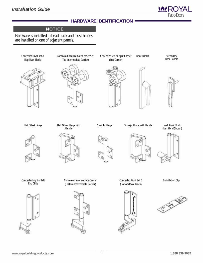
Hardware is installed in head track and most hinges are installed on one of adjacent panels.
Concealed Pivot set A(Top Pivot Block)
Concealed Intermediate Carrier Set(Top Intermediate Carrier)
Half Offset Hinge with Handle
Half Offset Hinge Straight Hinge with HandleStraight Hinge Wall Pivot Block(Left Hand Shown)
Concealed Pivot Set B(Bottom Pivot Block)
Concealed Intermediate Carrier(Bottom Intermediate Carrier)
Concealed left or right Carrier(End Carrier)
Door Handle
Concealed right or left End Glide
Installation Clip
Secondary Door Handle
1.888.339.9085
1. Assemble Frame• Remove frame components (sill, side jambs,
& head jamb) from package• Place frame components on flat surface interior
side down. Protect frame components from damage.• Apply manufacturer supplied head & sill Gaskets
to both the left & right side jambs as shown.• Secure sill to side jamb by installing supplied
screws (#10 x 3") through the exterior of the side jamb into pre-drilled pilot holes until a tight, even fit has been attained.
• Secure head jamb to side jamb by installing supplied screws (#10 x 3") through the exterior of the side jamb into pre-drilled pilot holes until at tight, even fit has been attained.
• Repeat above for opposite side
www.royalbuildingproducts.com9
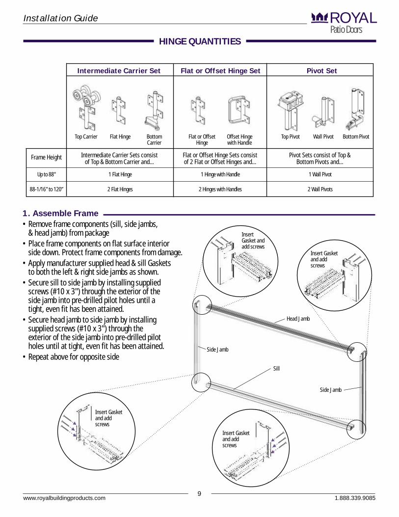
HINGE QUANTITIES
Installation GuidePatio DoorsROYAL
Side Jamb
Head Jamb
Sill
Side Jamb
Intermediate Carrier Set Flat or Offset Hinge Set Pivot Set
Offset Hinge with Handle
Flat or Offset Hinge
Top Pivot Wall Pivot Bottom PivotTop Carrier Flat Hinge Bottom Carrier
Intermediate Carrier Sets consist of Top & Bottom Carrier and...
Flat or Offset Hinge Sets consist of 2 Flat or Offset Hinges and...
Pivot Sets consist of Top & Bottom Pivots and...
Up to 88"
88-1/16" to 120”
Frame Height
1 Flat Hinge
2 Flat Hinges
1 Hinge with Handle
2 Hinges with Handles
1 Wall Pivot
2 Wall Pivots
Insert Gasket and add screws
Insert Gasket and add screws
Insert Gasket and add screws
Insert Gasket and add screws
1.888.339.9085
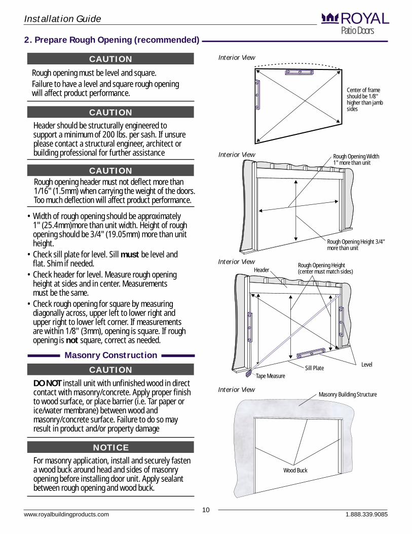
CAUTIONRough opening must be level and square.Failure to have a level and square rough opening will affect product performance.
• Width of rough opening should be approximately 1" (25.4mm)more than unit width. Height of rough opening should be 3/4" (19.05mm) more than unit height.
• Check sill plate for level. Sill must be level and flat. Shim if needed.
• Check header for level. Measure rough opening height at sides and in center. Measurements must be the same.
• Check rough opening for square by measuring diagonally across, upper left to lower right and upper right to lower left corner. If measurements are within 1/8" (3mm), opening is square. If rough opening is not square, correct as needed.
CAUTIONRough opening header must not deflect more than 1/16" (1.5mm) when carrying the weight of the doors. Too much deflection will affect product performance.
CAUTIONDO NOT install unit with unfinished wood in direct contact with masonry/concrete. Apply proper finish to wood surface, or place barrier (i.e. Tar paper or ice/water membrane) between wood and masonry/concrete surface. Failure to do so may result in product and/or property damage
NOTICEFor masonry application, install and securely fasten a wood buck around head and sides of masonry opening before installing door unit. Apply sealant between rough opening and wood buck.
Rough Opening Width 1" more than unit
Rough Opening Height 3/4" more than unit
Interior View
Interior View
Interior View
www.royalbuildingproducts.com10
Installation GuidePatio DoorsROYAL
2. Prepare Rough Opening (recommended)
Masonry Construction
Rough Opening Height (center must match sides)
LevelSill PlateTape Measure
Header
Wood Buck
Masonry Building Structure
CAUTIONHeader should be structurally engineered to support a minimum of 200 lbs. per sash. If unsure please contact a structural engineer, architect or building professional for further assistance
1.888.339.9085
Center of frame should be 1/8" higher than jamb sides
Interior View
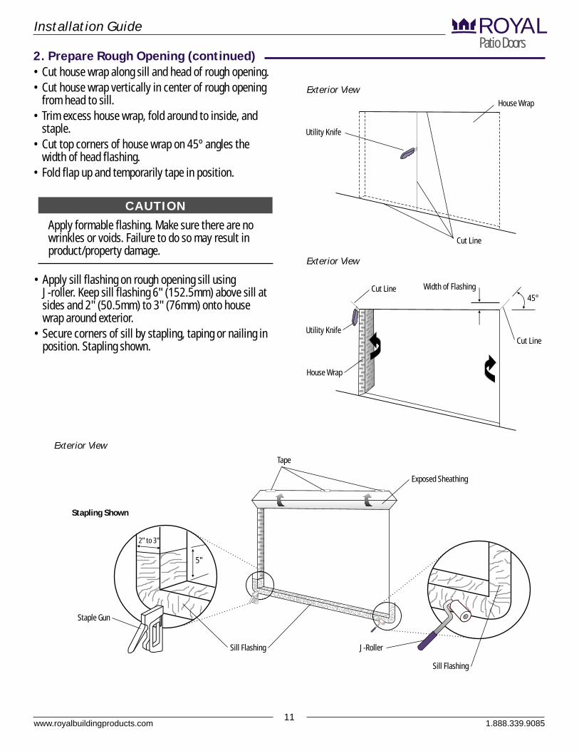
Apply formable flashing. Make sure there are no wrinkles or voids. Failure to do so may result in product/property damage.
• Cut house wrap along sill and head of rough opening.• Cut house wrap vertically in center of rough opening
from head to sill.• Trim excess house wrap, fold around to inside, and
staple.• Cut top corners of house wrap on 45º angles the
width of head flashing.• Fold flap up and temporarily tape in position.
• Apply sill flashing on rough opening sill using J-roller. Keep sill flashing 6" (152.5mm) above sill at sides and 2" (50.5mm) to 3" (76mm) onto house wrap around exterior.
• Secure corners of sill by stapling, taping or nailing in position. Stapling shown.
CAUTION
www.royalbuildingproducts.com11
Installation GuidePatio DoorsROYAL
2. Prepare Rough Opening (continued)
House Wrap
Cut Line
Exterior View
Exterior View
Width of Flashing
Utility Knife
Cut Line45°
Utility Knife
House Wrap
Cut Line
Exterior View
Exposed Sheathing
Tape
5"
2" to 3"
Staple Gun
Sill Flashing
Stapling Shown
Sill Flashing
J-Roller
1.888.339.9085

2. Prepare Rough Opening (continued)
www.royalbuildingproducts.com12
Installation GuidePatio DoorsROYAL
Exterior View
Sill Plate
5-3 "/4
Sealant
Sealant (in Corners)
Chalk Gun
• Apply four, continuous 3/8" (9.5mm) beads of sealant along sill plate of rough opening full length. Space beads 3/4" (19mm), 2-1/2" (63.5mm), 4-1/2" (114.5mm) and 5-3/4" (146mm) from exterior edge.
• Apply a liberal amount of sealant in bottom corners.
4-1 "/2
2-1 "/2
3/4"
1.888.339.9085
www.royalbuildingproducts.com13
Installation GuidePatio DoorsROYAL
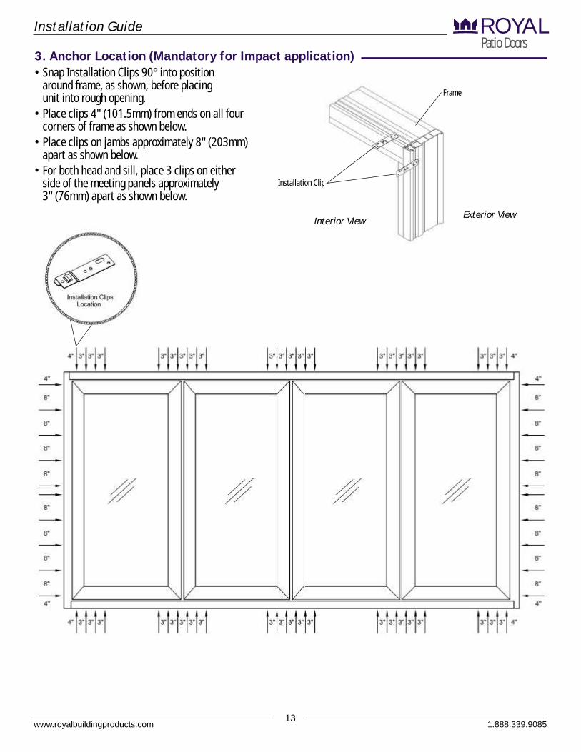
3. Anchor Location (Mandatory for Impact application)• Snap Installation Clips 90° into position
around frame, as shown, before placing unit into rough opening.
• Place clips 4" (101.5mm) from ends on all four corners of frame as shown below.
• Place clips on jambs approximately 8" (203mm) apart as shown below.
• For both head and sill, place 3 clips on either side of the meeting panels approximately 3" (76mm) apart as shown below.
Installation Clip
Frame
Interior ViewExterior View
1.888.339.9085

www.royalbuildingproducts.com14
Installation GuidePatio DoorsROYAL
4. Optional Low Profile Sill installation
1.888.339.9085
4. (Optionl Low Profile sill installations) MUST be followed prior proceeding to 5. (Install Frame) if you are installing an Overture Folding Patio Door with the Low Profile Sill option.Please proceed to 5. (Install Frame) if you are installing an Overture Folding Patio Door without the Low Profile Sill option
NOTICE
• Step 1. Before assembling the frame, please ensure your floor is flat and level. A channel must be notched out into the floor to accommodate your Low Profile Sill. Notch out must be a minimum of 1-5/8" (144.28mm) wide by 9/16" (14.29mm) to 5/8" (15.88mm) deep. The length of the channel will be determined by the width of the door. (See note on drawings)
• Step 2. The channel must be straight to ensure proper operation of the door. As a trial, place Low Profile Sill into the channel to ensure the sill rests flat, level and consistent along span of the door opening.
• Step 3. Once step 2 is confirmed, apply gaskets into jambs (both head and sill) and fasten the frame together following the instructions in the manual provided.
• Step 4. Position the frame so that it can be tilted upwards into position and directly into the channel.
• Step 5. Tilt the completed frame towards interior, exposing the base of the Low Profile Sill. Apply the first bead of silicone onto the exterior tip of the sill.
• Step 6. Apply a second bead of silicone beneath the thermal break of the sill (as shown in drawing). As well, prior to placing the frame into the channel, fill the channel with a bead of silicone as shown in the drawings provided.
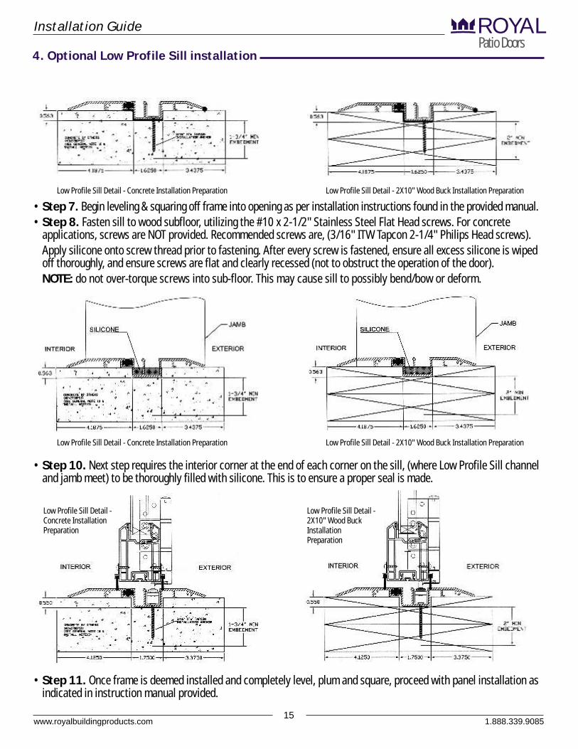
Low Profile Sill Detail - Concrete Installation Preparation Low Profile Sill Detail - 2X10" Wood Buck Installation Preparation
Low Profile Sill Detail - Concrete Installation Preparation Low Profile Sill Detail - 2X10" Wood Buck Installation Preparation
Low Profile Sill Detail - Concrete Installation Preparation Low Profile Sill Detail - 2X10" Wood Buck Installation Preparation
www.royalbuildingproducts.com15
Installation GuidePatio DoorsROYAL
1.888.339.9085
• Step 7. Begin leveling & squaring off frame into opening as per installation instructions found in the provided manual.• Step 8. Fasten sill to wood subfloor, utilizing the #10 x 2-1/2" Stainless Steel Flat Head screws. For concrete
applications, screws are NOT provided. Recommended screws are, (3/16" ITW Tapcon 2-1/4" Philips Head screws).Apply silicone onto screw thread prior to fastening. After every screw is fastened, ensure all excess silicone is wiped off thoroughly, and ensure screws are flat and clearly recessed (not to obstruct the operation of the door).NOTE: do not over-torque screws into sub-floor. This may cause sill to possibly bend/bow or deform.
• Step 10. Next step requires the interior corner at the end of each corner on the sill, (where Low Profile Sill channel and jamb meet) to be thoroughly filled with silicone. This is to ensure a proper seal is made.
• Step 11. Once frame is deemed installed and completely level, plum and square, proceed with panel installation as indicated in instruction manual provided.
Low Profile Sill Detail - Concrete Installation Preparation Low Profile Sill Detail - 2X10" Wood Buck Installation Preparation
Low Profile Sill Detail - Concrete Installation Preparation Low Profile Sill Detail - 2X10" Wood Buck Installation Preparation
Low Profile Sill Detail - Concrete Installation Preparation
Low Profile Sill Detail - 2X10" Wood Buck Installation Preparation
4. Optional Low Profile Sill installation
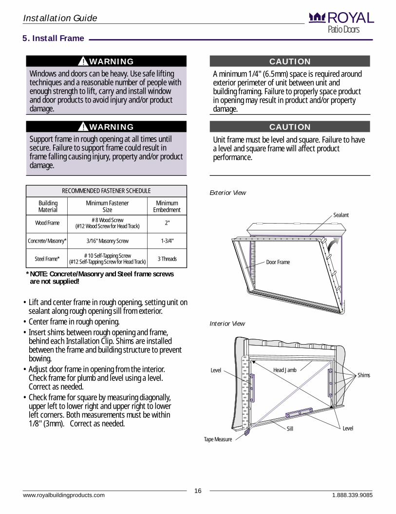
A minimum 1/4" (6.5mm) space is required around exterior perimeter of unit between unit and building framing. Failure to properly space product in opening may result in product and/or property damage.
• Lift and center frame in rough opening, setting unit on sealant along rough opening sill from exterior.
• Center frame in rough opening.• Insert shims between rough opening and frame,
behind each Installation Clip. Shims are installed between the frame and building structure to prevent bowing.
• Adjust door frame in opening from the interior. Check frame for plumb and level using a level. Correct as needed.
• Check frame for square by measuring diagonally, upper left to lower right and upper right to lower left corners. Both measurements must be within 1/8" (3mm). Correct as needed.
Unit frame must be level and square. Failure to have a level and square frame will affect product performance.
www.royalbuildingproducts.com16
Installation GuidePatio DoorsROYAL
WARNING! CAUTIONWindows and doors can be heavy. Use safe lifting techniques and a reasonable number of people with enough strength to lift, carry and install window and door products to avoid injury and/or product damage.
5. Install Frame
WARNING!
Support frame in rough opening at all times until secure. Failure to support frame could result in frame falling causing injury, property and/or product damage.
CAUTION
RECOMMENDED FASTENER SCHEDULE
Wood Frame
Concrete/ Masonry*
Steel Frame*
Building Material
# 8 Wood Screw (#12 Wood Screw for Head Track)
3/16" Masonry Screw
# 10 Self-Tapping Screw (#12 Self-Tapping Screw for Head Track)
Minimum Fastener Size
Minimum Embedment
2"
1-3/4"
3 Threads
Interior View
LevelSill
Tape Measure
Head JambLevelShims
Sealant
Exterior View
Door Frame
*NOTE: Concrete/Masonry and Steel frame screws are not supplied!
1.888.339.9085
www.royalbuildingproducts.com17
Installation GuidePatio DoorsROYAL
5. Install Frame (continued)
Side Jamb
Shim
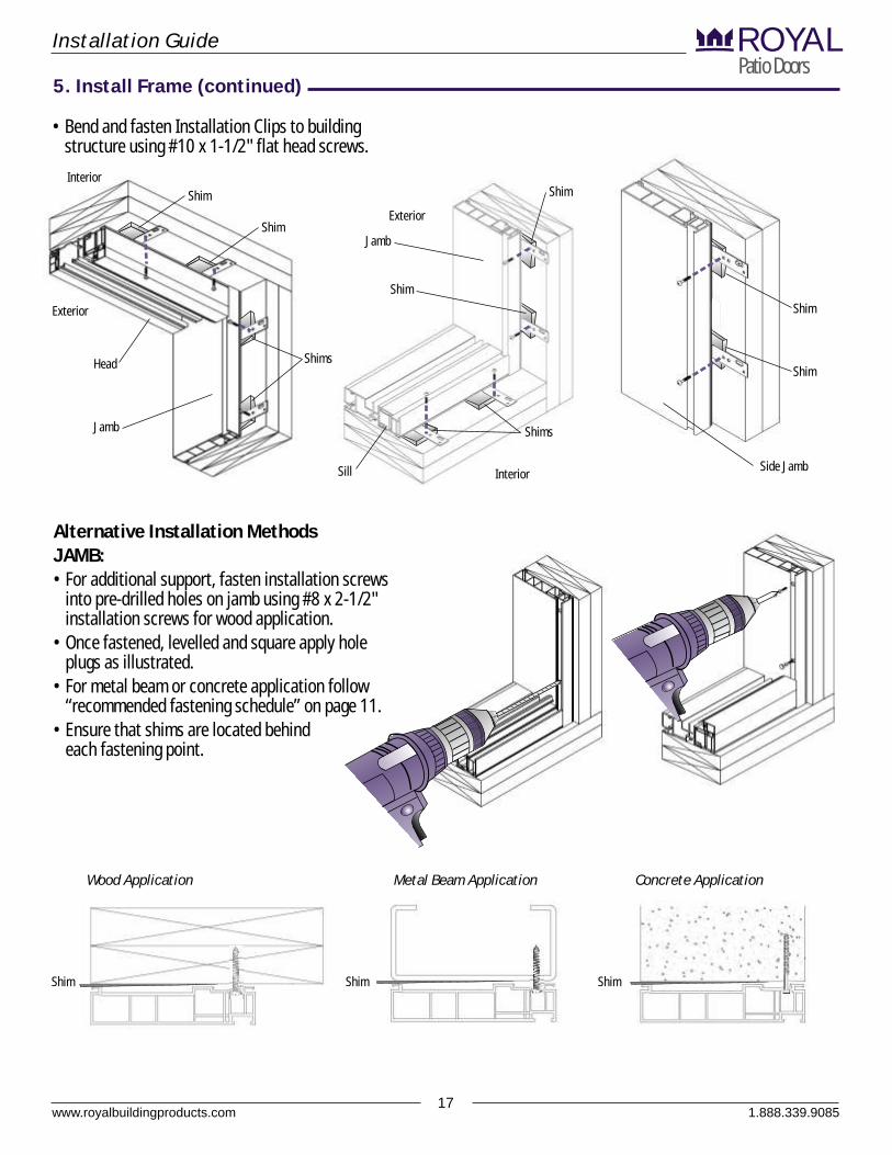
• Bend and fasten Installation Clips to building structure using #10 x 1-1/2" flat head screws.
1.888.339.9085
Jamb
Interior
Exterior
Head
Jamb
Interior
Exterior
Sill
Alternative Installation MethodsJAMB:• For additional support, fasten installation screws
into pre-drilled holes on jamb using #8 x 2-1/2" installation screws for wood application.
• Once fastened, levelled and square apply hole plugs as illustrated.
• For metal beam or concrete application follow “recommended fastening schedule” on page 11.
• Ensure that shims are located behind each fastening point.
Wood Application Metal Beam Application Concrete Application
Shim
Shim
Shim Shim Shim
Shims
Shim
Shim
Shims
Shim

Head track must be secured with proper size and quantity of screws. Secure head track with #12 or larger screws in all predrilled holes in head track. Screws must penetrate the rough opening header by at least 1-1/2" (38mm). Failure to do so could result in product and/or property damage.
Head jamb must be level or have slight (1/8" maximum) camber up in center.
HEAD:• Install supplied (from screw pack) #12 x 3-1/2" pan
head screws through all predrilled holes in head track. Screws must penetrate the rough opening header by at least 1-1/2" (38mm). Use longer screw if required. Shim between head jamb and rough opening header. Use screws to keep head jamb level. Once fastened, ensure that you have checked for proper level and consistent opening throughout the width of the door.
* Ensure not to over torque/tighten the pan screws that secure the head track to the rough opening header. This will cause the tracks to bind.
www.royalbuildingproducts.com18
Installation GuidePatio DoorsROYAL
NOTICE
5. Install Frame (continued)
CAUTION
Wood Application Metal Beam Application
Pre-drilled Hole
Head Jamb
Head Track
Drill/Driver
1.888.339.9085
1/4" (6.5mm) Maximum
Space
Interior View
Sill
Tape Measure
Head Jamb
Level
Shims
Tape Measure
ShimSh
im
Once the frame has been installed and prior to installing the hardware please wipe the top and bottom tracks clean to ensure that the tracks are clear of any debris.
NOTE
www.royalbuildingproducts.com19
Installation GuidePatio DoorsROYAL
5. Install Frame (continued)
1.888.339.9085
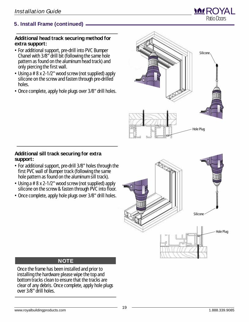
Additional head track securing method for extra support:• For additional support, pre-drill into PVC Bumper
Chanel with 3/8" drill bit (following the same hole pattern as found on the aluminum head track) and only piercing the first wall.
• Using a # 8 x 2-1/2" wood screw (not supplied) apply silicone on the screw and fasten through pre-drilled holes.
• Once complete, apply hole plugs over 3/8" drill holes.
Additional sill track securing for extra support:• For additional support, pre-drill 3/8" holes through the
first PVC wall of Bumper track (following the same hole pattern as found on the aluminum sill track).
• Using a # 8 x 2-1/2" wood screw (not supplied) apply silicone on the screw & fasten through PVC into floor.
• Once complete, apply hole plugs over 3/8" drill holes.
Once the frame has been installed and prior to installing the hardware please wipe the top and bottom tracks clean to ensure that the tracks are clear of any debris. Once complete, apply hole plugs over 3/8" drill holes.
NOTE
Silicone
Silicone
Hole Plug
Hole Plug
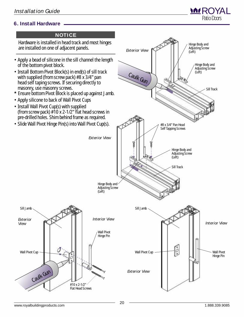
Hardware is installed in head track and most hinges are installed on one of adjacent panels.
www.royalbuildingproducts.com20
Installation GuidePatio DoorsROYAL
6. Install Hardware
NOTICE
Sill Jamb
Wall Pivot Cup
Interior ViewInterior View
Sill Jamb
Wall Pivot Cup
#10 x 2-1/2" Flat Head Screws
Wall Pivot Hinge Pin
Wall Pivot Hinge Pin
Hinge Body and Adjusting Screw (Left)
Hinge Body and Adjusting Screw (Left)
Sill Track
Exterior View
Exterior View
Exterior View
1.888.339.9085
Hinge Body and Adjusting Screw (Left)
Hinge Body and Adjusting Screw (Left)
Sill Track
Exterior View
Ca lk Guu n
• Apply a bead of silicone in the sill channel the length of the bottom pivot block.
• Install Bottom Pivot Block(s) in end(s) of sill track with supplied (from screw pack) #8 x 3/4" pan head self taping screws. If securing directly to masonry, use masonry screws.
* Ensure bottom Pivot Block is placed up against Jamb.• Apply silicone to back of Wall Pivot Cups• Install Wall Pivot Cup(s) with supplied
(from screw pack) #10 x 2-1/2" flat head screws in pre-drilled holes. Shim behind frame as required.
• Slide Wall Pivot Hinge Pin(s) into Wall Pivot Cup(s). #8 x 3/4" Pan Head Self Tapping Screws
Clk G
au un
Installation GuidePatio DoorsROYAL
www.royalbuildingproducts.com21
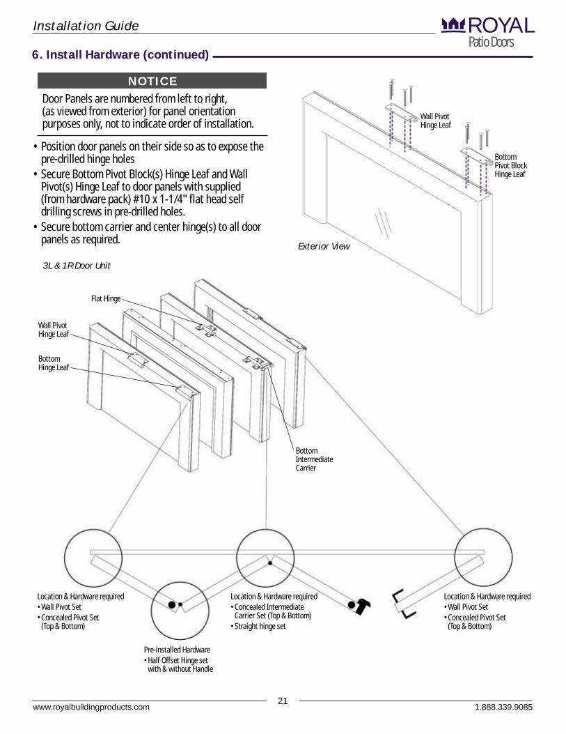
Door Panels are numbered from left to right, (as viewed from exterior) for panel orientation purposes only, not to indicate order of installation.
• Position door panels on their side so as to expose the pre-drilled hinge holes
• Secure Bottom Pivot Block(s) Hinge Leaf and Wall Pivot(s) Hinge Leaf to door panels with supplied (from hardware pack) #10 x 1-1/4" flat head self drilling screws in pre-drilled holes.
• Secure bottom carrier and center hinge(s) to all door panels as required.
NOTICE
3L & 1R Door Unit
Wall Pivot Hinge Leaf
Bottom Pivot Block Hinge Leaf
1.888.339.9085
Wall Pivot Hinge Leaf
Flat Hinge
Bottom Intermediate Carrier
Exterior View
Bottom Hinge Leaf
6. Install Hardware (continued)
Location & Hardware required•Wall Pivot Set•Concealed Pivot Set
(Top & Bottom)
Pre-installed Hardware•Half Offset Hinge set
with & without Handle
Location & Hardware required•Concealed Intermediate
Carrier Set (Top & Bottom)•Straight hinge set
Location & Hardware required•Wall Pivot Set•Concealed Pivot Set
(Top & Bottom)
Installation GuidePatio DoorsROYAL
www.royalbuildingproducts.com22
1.888.339.9085
6. Install Hardware (continued)
3rd
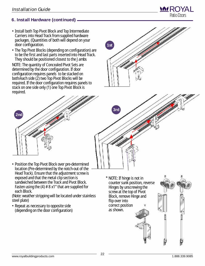
• Position the Top Pivot Block over pre-determined location (Pre-determined by the notch-out of the Head Track). Ensure that the adjustment screw is exposed and that the metal clip section is sandwiched between the Track and Pivot Block. Fasten using the (4) # 8 x1" that are supplied for each Block.
(Note: weather stripping will be located under stainless steel plate)• Repeat as necessary to opposite side
(depending on the door configuration)
• Install both Top Pivot Block and Top Intermediate Carriers into Head Track from supplied hardware packages. (Quantities of both will depend on your door configuration.
• The Top Pivot Blocks (depending on configuration) are to be the first and last parts inserted into Head Track. They should be positioned closest to the Jambs
NOTE: The quantity of Concealed Pivot Sets are determined by the door configuration. If door configuration requires panels to be stacked on both/each side (2) two Top Pivot Blocks will be required. If the door configuration requires panels to stack on one side only (1) one Top Pivot Block is required.
* NOTE: If hinge is not in counter sunk position, reverse Hinges by unscrewing the screw at the top of Pivot Block, remove Hinge and flip over into correct position as shown.
1st
2nd
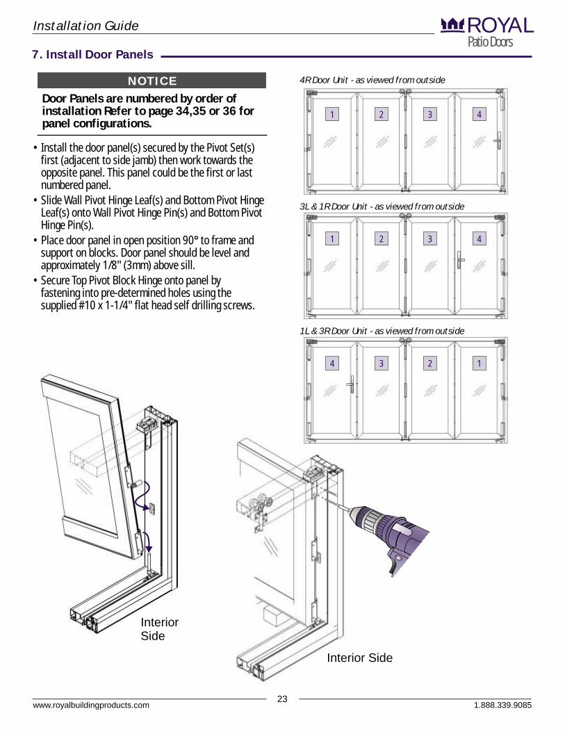
Door Panels are numbered by order of installation Refer to page 34,35 or 36 for panel configurations.
• Install the door panel(s) secured by the Pivot Set(s) first (adjacent to side jamb) then work towards the opposite panel. This panel could be the first or last numbered panel.
• Slide Wall Pivot Hinge Leaf(s) and Bottom Pivot Hinge Leaf(s) onto Wall Pivot Hinge Pin(s) and Bottom Pivot Hinge Pin(s).
• Place door panel in open position 90° to frame and support on blocks. Door panel should be level and approximately 1/8" (3mm) above sill.
• Secure Top Pivot Block Hinge onto panel by fastening into pre-determined holes using the supplied #10 x 1-1/4" flat head self drilling screws.
www.royalbuildingproducts.com23
Installation GuidePatio DoorsROYAL
7. Install Door Panels
NOTICE 4R Door Unit - as viewed from outside
3L & 1R Door Unit - as viewed from outside
1 2 3 4
1 2 3 4
1.888.339.9085
1L & 3R Door Unit - as viewed from outside
4 3 2 1
InteriorSide
Interior Side
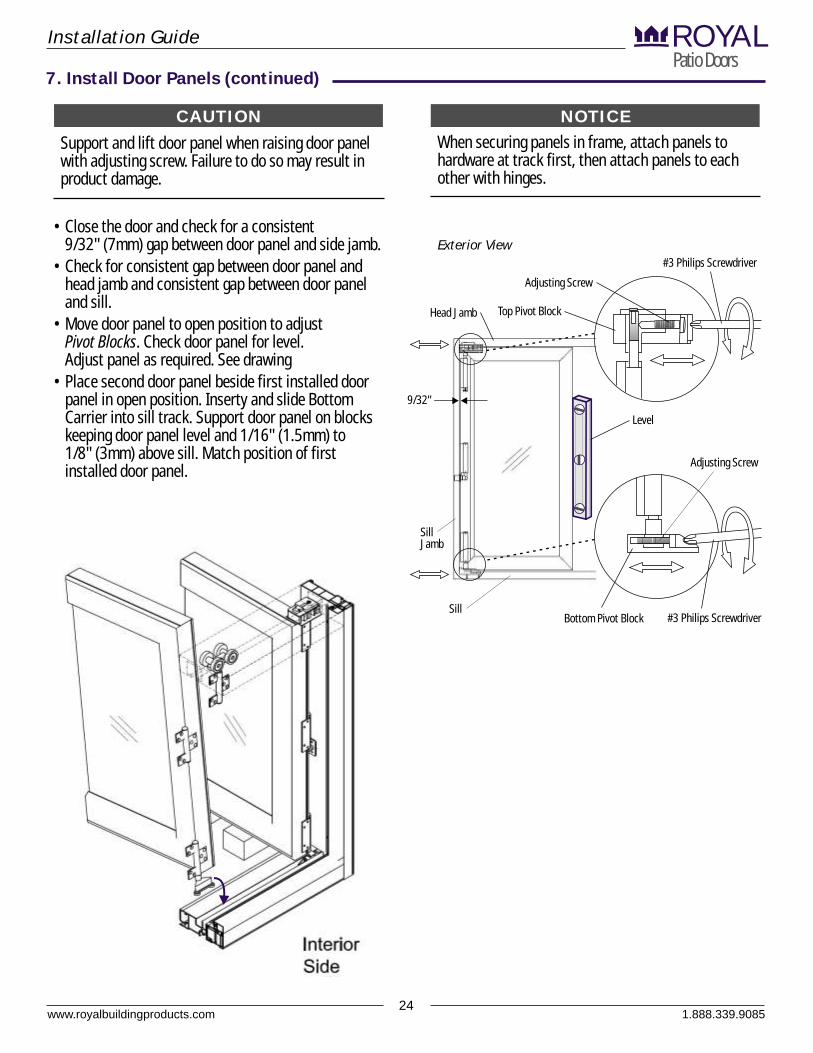
Support and lift door panel when raising door panel with adjusting screw. Failure to do so may result in product damage.
When securing panels in frame, attach panels to hardware at track first, then attach panels to each other with hinges.
• Close the door and check for a consistent 9/32" (7mm) gap between door panel and side jamb.
• Check for consistent gap between door panel and head jamb and consistent gap between door panel and sill.
• Move door panel to open position to adjust Pivot Blocks. Check door panel for level. Adjust panel as required. See drawing
• Place second door panel beside first installed door panel in open position. Inserty and slide Bottom Carrier into sill track. Support door panel on blocks keeping door panel level and 1/16" (1.5mm) to 1/8" (3mm) above sill. Match position of first installed door panel.
www.royalbuildingproducts.com24
Installation GuidePatio DoorsROYAL
7. Install Door Panels (continued)
NOTICECAUTION
Head Jamb Top Pivot Block
Adjusting Screw
#3 Philips Screwdriver
Bottom Pivot Block
Adjusting Screw
#3 Philips Screwdriver
Level
Sill
Sill Jamb
9/32"
Exterior View
1.888.339.9085
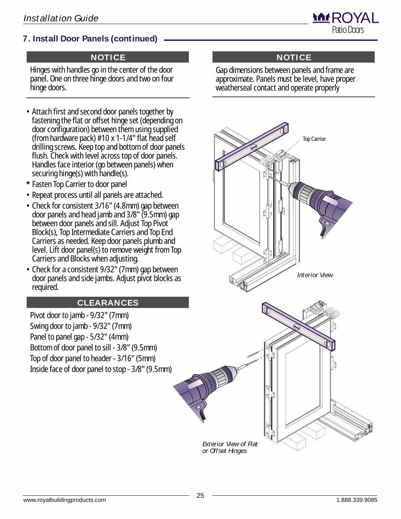
Hinges with handles go in the center of the door panel. One on three hinge doors and two on four hinge doors.
• Attach first and second door panels together by fastening the flat or offset hinge set (depending on door configuration) between them using supplied (from hardware pack) #10 x 1-1/4" flat head self drilling screws. Keep top and bottom of door panels flush. Check with level across top of door panels. Handles face interior (go between panels) when securing hinge(s) with handle(s).
* Fasten Top Carrier to door panel• Repeat process until all panels are attached.• Check for consistent 3/16" (4.8mm) gap between
door panels and head jamb and 3/8" (9.5mm) gap between door panels and sill. Adjust Top Pivot Block(s), Top Intermediate Carriers and Top End Carriers as needed. Keep door panels plumb and level. Lift door panel(s) to remove weight from Top Carriers and Blocks when adjusting.
• Check for a consistent 9/32" (7mm) gap between door panels and side jambs. Adjust pivot blocks as required.
www.royalbuildingproducts.com25
Installation GuidePatio DoorsROYAL
Gap dimensions between panels and frame are approximate. Panels must be level, have proper weatherseal contact and operate properly
7. Install Door Panels (continued)
NOTICENOTICE
Interior View
Exterior View of Flat or Offset Hinges
1.888.339.9085
Top Carrior
Pivot door to jamb - 9/32" (7mm)Swing door to jamb - 9/32" (7mm)Panel to panel gap - 5/32" (4mm)Bottom of door panel to sill - 3/8" (9.5mm)Top of door panel to header - 3/16" (5mm)Inside face of door panel to stop - 3/8" (9.5mm)
CLEARANCES
www.royalbuildingproducts.com26
Installation GuidePatio DoorsROYAL
8. Keeper, Handle and Cylinder Installation
1.888.339.9085
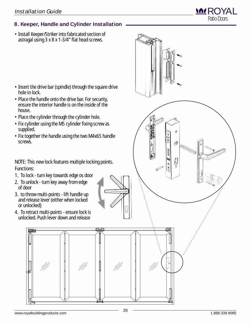
• Install Keeper/Striker into fabricated section of astragal using 3 x 8 x 1-3/4" flat head screws.
• Insert the drive bar (spindle) through the square drive hole in lock.
• Place the handle onto the drive bar. For security, ensure the interior handle is on the inside of the house.
• Place the cylinder through the cylinder hole.• Fix cylinder using the M5 cylinder fixing screw as
supplied.• Fix together the handle using the two M4x65 handle
screws.
NOTE: This new lock features multiple locking points.Functions:1. To lock - turn key towards edge os door2. To unlock - turn key away from edge
of door3. to throw multi-points - lift handle up
and release lever (either when locked or unlocked)
4. To retract multi-points - ensure lock is unlocked. Push lever down and release
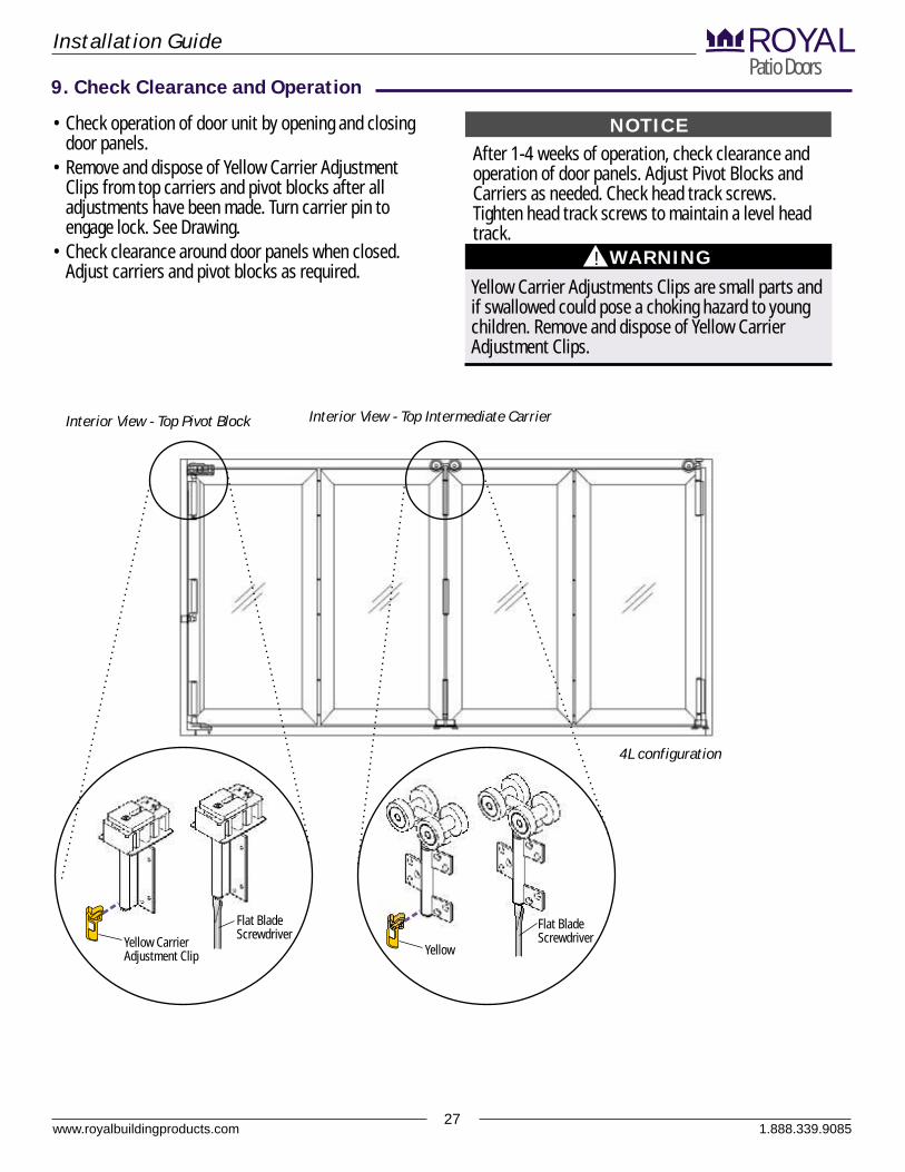
• Check operation of door unit by opening and closing door panels.
• Remove and dispose of Yellow Carrier Adjustment Clips from top carriers and pivot blocks after all adjustments have been made. Turn carrier pin to engage lock. See Drawing.
• Check clearance around door panels when closed. Adjust carriers and pivot blocks as required.
Yellow Carrier Adjustments Clips are small parts and if swallowed could pose a choking hazard to young children. Remove and dispose of Yellow Carrier Adjustment Clips.
www.royalbuildingproducts.com27
Installation GuidePatio DoorsROYAL
9. Check Clearance and Operation
WARNING!
Interior View - Top Intermediate Carrier
Flat Blade Screwdriver
Yellow
Flat Blade Screwdriver
Yellow Carrier Adjustment Clip
After 1-4 weeks of operation, check clearance and operation of door panels. Adjust Pivot Blocks and Carriers as needed. Check head track screws. Tighten head track screws to maintain a level head track.
NOTICE
Interior View - Top Pivot Block
1.888.339.9085
4L configuration
B
ROYALPatio Doors
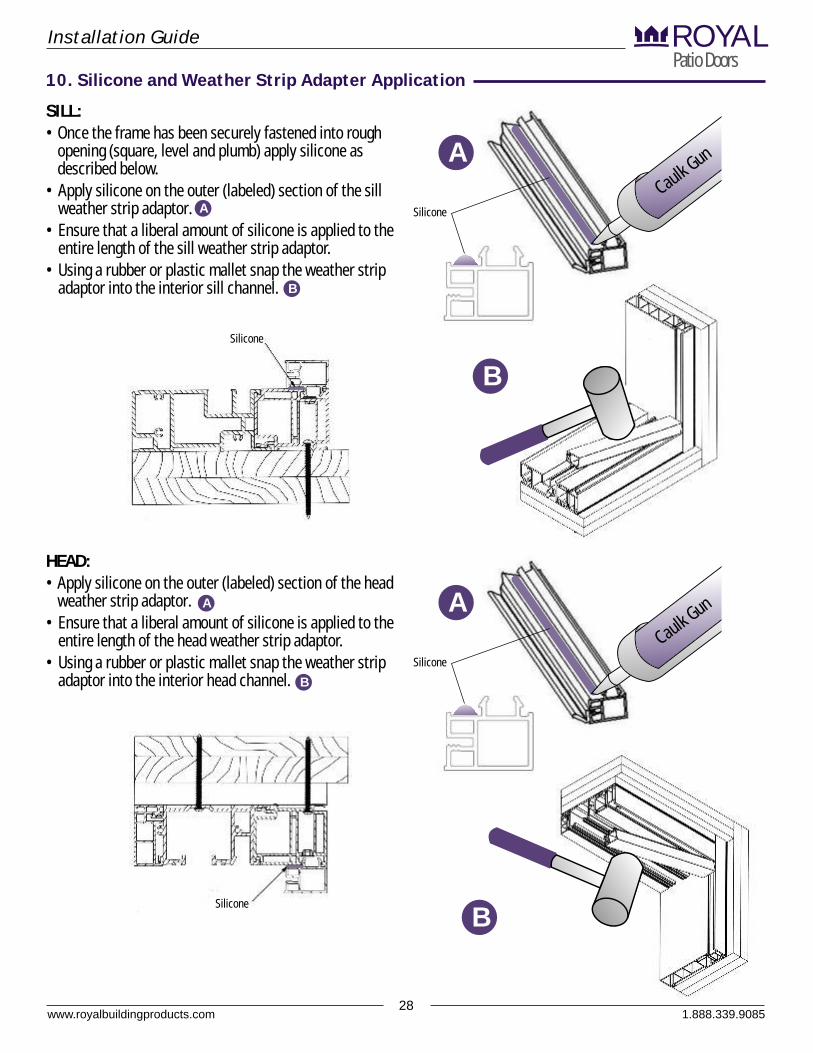
SILL:• Once the frame has been securely fastened into rough
opening (square, level and plumb) apply silicone as described below.
• Apply silicone on the outer (labeled) section of the sill weather strip adaptor.
• Ensure that a liberal amount of silicone is applied to the entire length of the sill weather strip adaptor.
• Using a rubber or plastic mallet snap the weather strip adaptor into the interior sill channel.
Installation Guide
Caulk Gun
Silicone
A
A
B
10. Silicone and Weather Strip Adapter Application
Silicone
B
HEAD:• Apply silicone on the outer (labeled) section of the head
weather strip adaptor.• Ensure that a liberal amount of silicone is applied to the
entire length of the head weather strip adaptor.• Using a rubber or plastic mallet snap the weather strip
adaptor into the interior head channel.
Caulk Gun
Silicone
AA
B
Silicone
28www.royalbuildingproducts.com 1.888.339.9085
ROYALPatio Doors
29www.royalbuildingproducts.com
Installation Guide
1.888.339.9085
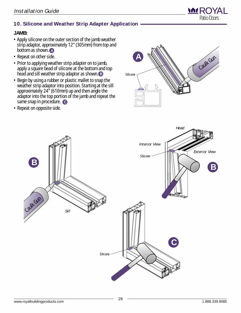
JAMB:• Apply silicone on the outer section of the jamb weather
strip adaptor, approximately 12" (305mm) from top and bottom as shown.
• Repeat on other side.• Prior to applying weather strip adapter on to jamb,
apply a square bead of silicone at the bottom and top head and sill weather strip adaptor as shown.
• Begin by using a rubber or plastic mallet to snap the weather strip adaptor into position. Starting at the sill approximately 24" (610mm) up and then angle the adaptor into the top portion of the jamb and repeat the same snap in procedure.
• Repeat on opposite side.
Interior View
Exterior View
Head
SillCk G
n
aulu
Ca Gun
ulk
Silicone
Silicone
Silicone
A
B
C
A
B
C
B
10. Silicone and Weather Strip Adapter Application
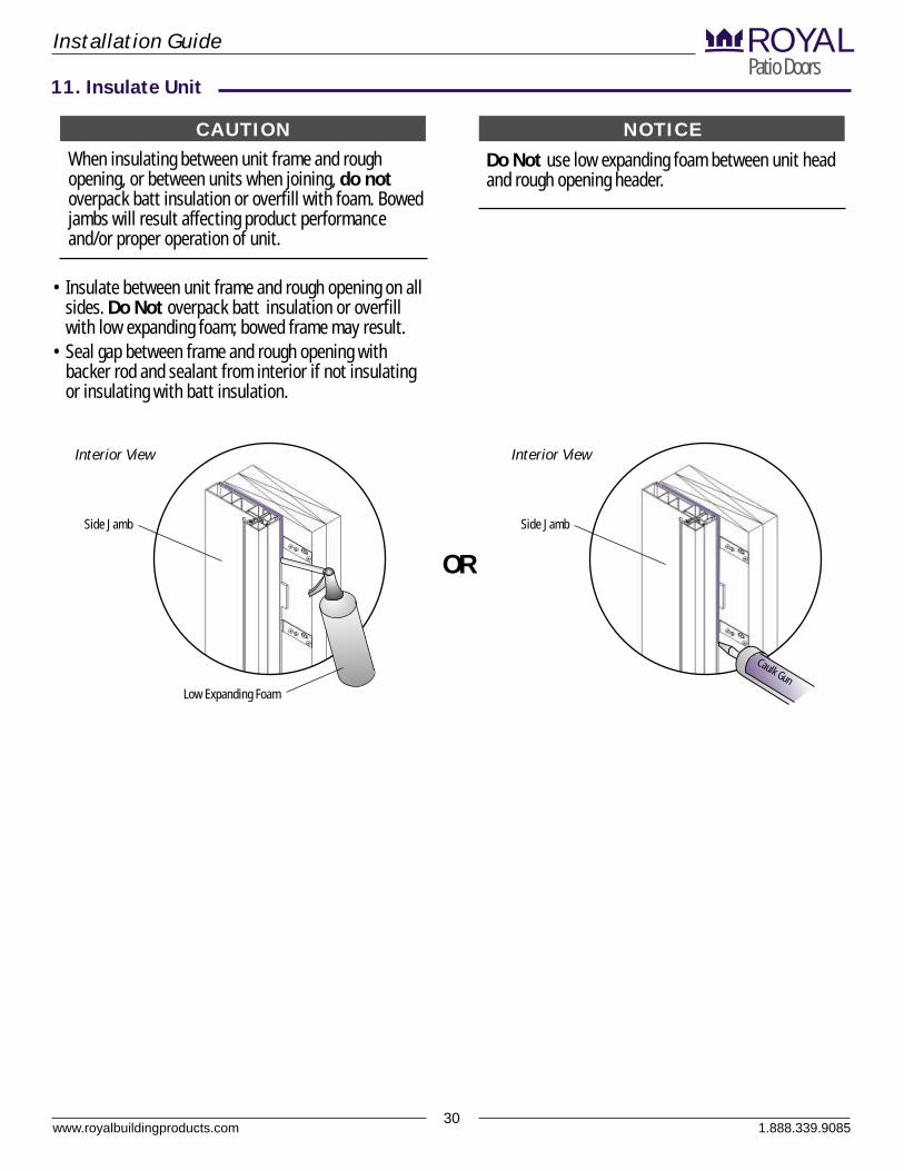
When insulating between unit frame and rough opening, or between units when joining, do not overpack batt insulation or overfill with foam. Bowed jambs will result affecting product performance and/or proper operation of unit.
Do Not use low expanding foam between unit head and rough opening header.
• Insulate between unit frame and rough opening on all sides. Do Not overpack batt insulation or overfill with low expanding foam; bowed frame may result.
• Seal gap between frame and rough opening with backer rod and sealant from interior if not insulating or insulating with batt insulation.
www.royalbuildingproducts.com30
Installation GuidePatio DoorsROYAL
11. Insulate Unit
NOTICECAUTION
Side Jamb
aC ulk Gun
Interior View
Side Jamb
Interior View
Low Expanding Foam
OR
1.888.339.9085
www.royalbuildingproducts.com31
Installation GuidePatio DoorsROYAL
1.888.339.9085
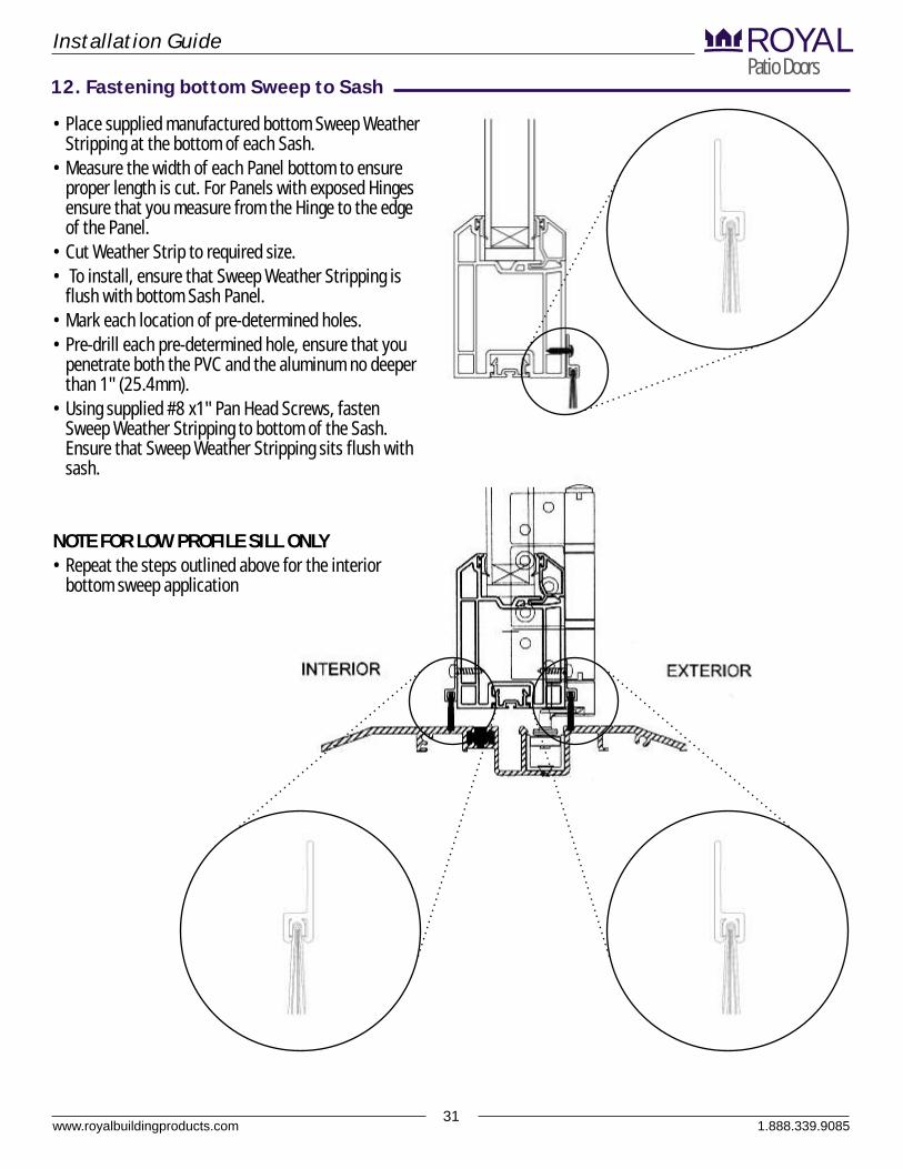
• Place supplied manufactured bottom Sweep Weather Stripping at the bottom of each Sash.
• Measure the width of each Panel bottom to ensure proper length is cut. For Panels with exposed Hinges ensure that you measure from the Hinge to the edge of the Panel.
• Cut Weather Strip to required size.• To install, ensure that Sweep Weather Stripping is
flush with bottom Sash Panel.• Mark each location of pre-determined holes.• Pre-drill each pre-determined hole, ensure that you
penetrate both the PVC and the aluminum no deeper than 1" (25.4mm).
• Using supplied #8 x1" Pan Head Screws, fasten Sweep Weather Stripping to bottom of the Sash. Ensure that Sweep Weather Stripping sits flush with sash.
NOTE FOR LOW PROFILE SILL ONLY• Repeat the steps outlined above for the interior
bottom sweep application
12. Fastening bottom Sweep to Sash
www.royalbuildingproducts.com32
Installation GuidePatio DoorsROYAL
1.888.339.9085
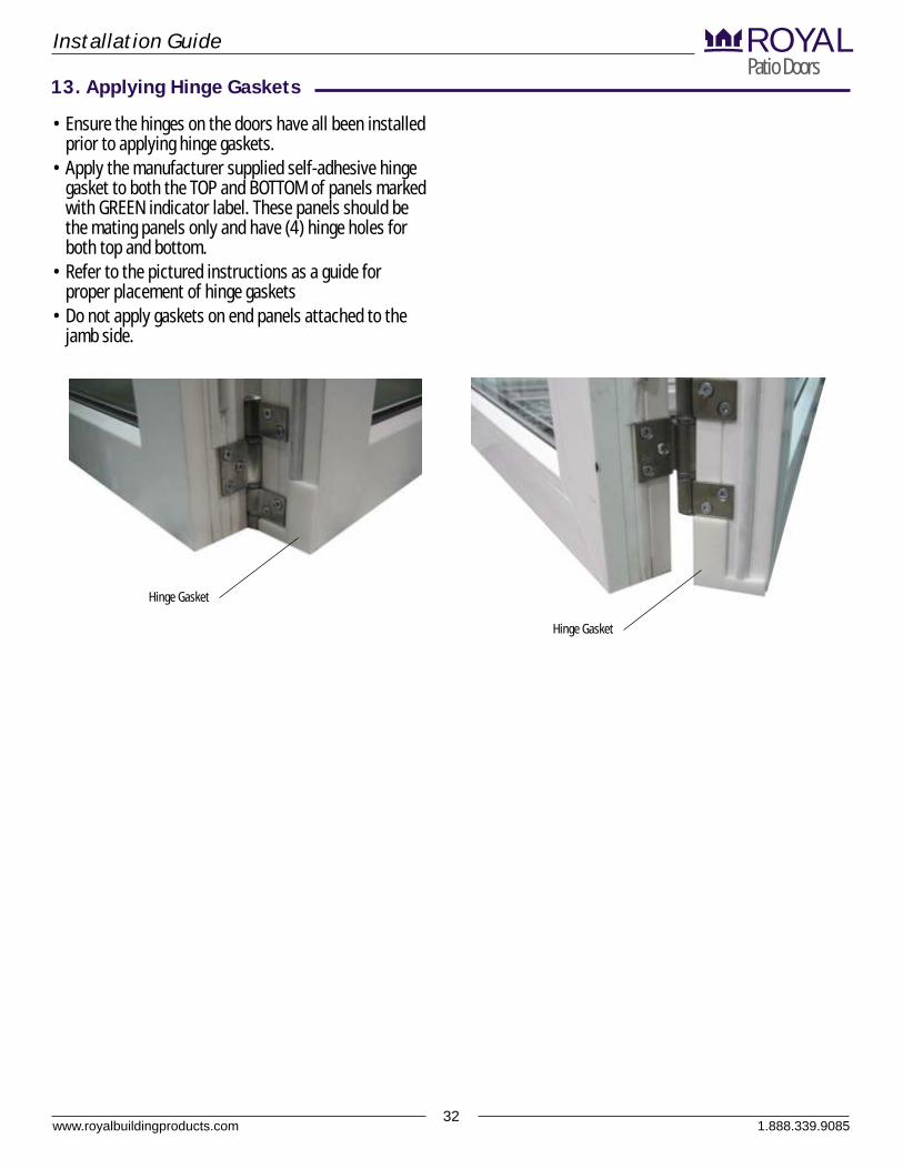
• Ensure the hinges on the doors have all been installed prior to applying hinge gaskets.
• Apply the manufacturer supplied self-adhesive hinge gasket to both the TOP and BOTTOM of panels marked with GREEN indicator label. These panels should be the mating panels only and have (4) hinge holes for both top and bottom.
• Refer to the pictured instructions as a guide for proper placement of hinge gaskets
• Do not apply gaskets on end panels attached to the jamb side.
13. Applying Hinge Gaskets
Hinge Gasket
Hinge Gasket

www.royalbuildingproducts.com33
Installation GuidePatio DoorsROYAL
14. Folding Door Configurations
Hardware Legend
1.888.339.9085
www.royalbuildingproducts.com34
Installation GuidePatio DoorsROYAL
1.888.339.9085
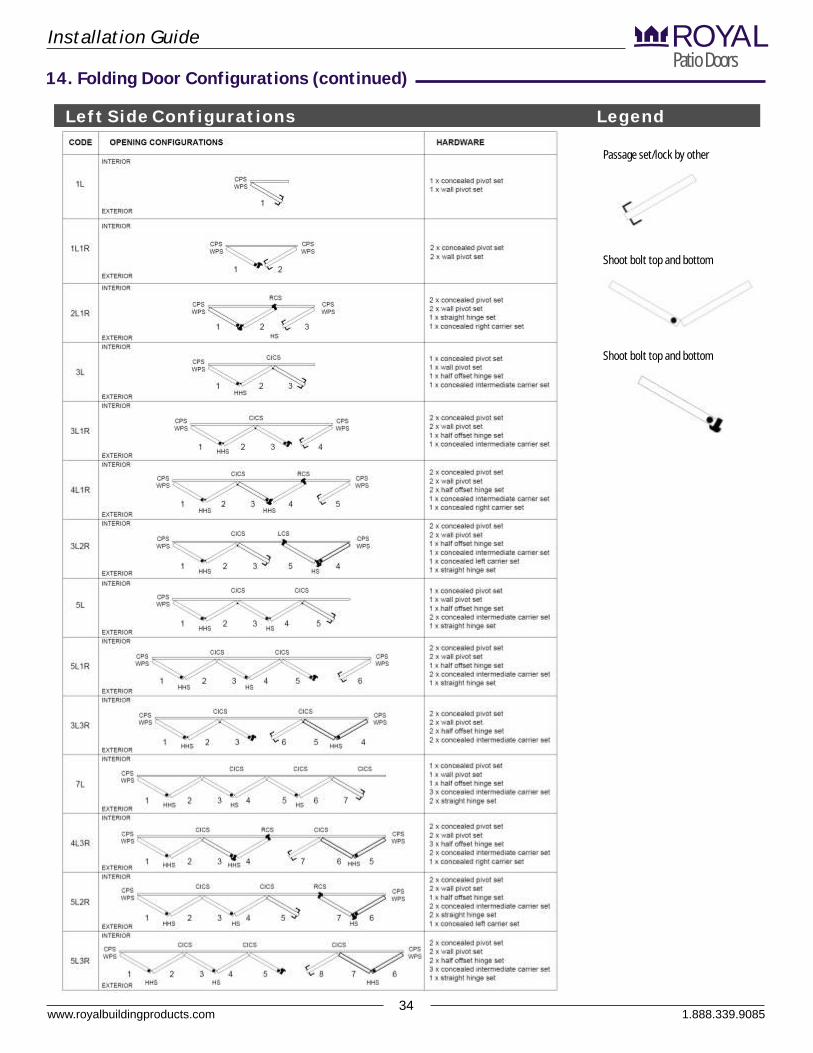
Left Side Configurations Legend
Passage set/lock by other
Shoot bolt top and bottom
Shoot bolt top and bottom
14. Folding Door Configurations (continued)
www.royalbuildingproducts.com35
Installation GuidePatio DoorsROYAL
14. Folding Door Configurations (continued)
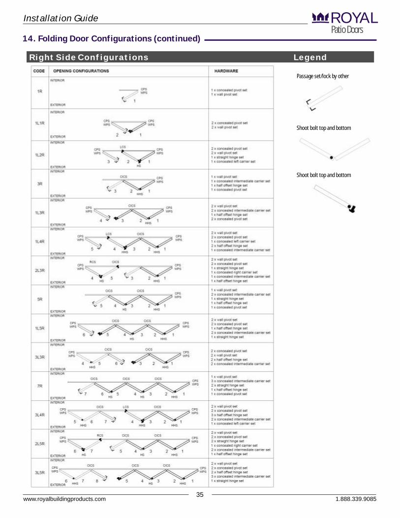
Right Side Configurations
1.888.339.9085
Legend
Passage set/lock by other
Shoot bolt top and bottom
Shoot bolt top and bottom
www.royalbuildingproducts.com36
Installation GuidePatio DoorsROYAL
14. Folding Door Configurations (continued)
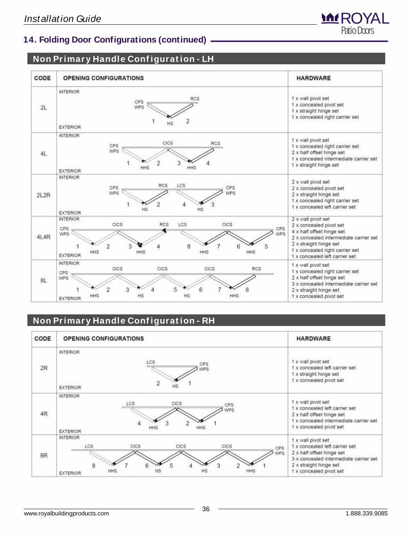
Non Primary Handle Configuration - LH
1.888.339.9085
Non Primary Handle Configuration - RH