overview of the resource allocation & control engine (race) ed mulholland tom damiano patrick...
TRANSCRIPT
Overview of the Resource Allocation Overview of the Resource Allocation & Control Engine (RACE)& Control Engine (RACE)
Ed MulhollandTom Damiano
Patrick Lardieri
Jai BalasubramanianJames HillWill Otte
Nishanth Shankaran
Douglas C. [email protected]
www.dre.vanderbilt.edu/~schmidt
2RACERACE
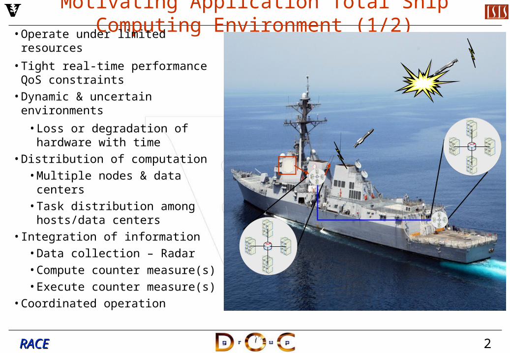
Motivating Application Total Ship Computing Environment (1/2)• Operate under limited resources
• Tight real-time performance QoS constraints
• Dynamic & uncertain environments
• Loss or degradation of hardware with time
• Distribution of computation• Multiple nodes & data centers• Task distribution among
hosts/data centers• Integration of information
• Data collection – Radar• Compute counter measure(s)• Execute counter measure(s)
• Coordinated operation
3RACERACE
Motivating Application Total Ship Computing Environment (2/2)
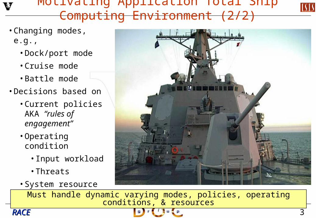
• Changing modes, e.g.,
• Dock/port mode
• Cruise mode
• Battle mode
• Decisions based on
• Current policies AKA “rules of engagement”
• Operating condition
• Input workload
• Threats
• System resource availability
Must handle dynamic varying modes, policies, operating conditions, & resources

4RACERACE
Terminology
• End-to-end periodic application represented as operational string of components • Classes of operational strings
• Mission Critical• High priority - mission is compromised if QoS requirements are not met
• House Keeping• Medium priority - desirable to meet QoS requirements, however mission is
not compromised if requirements are not met• QoS: End-to-end deadline• Operational strings simultaneously share resources – computing power & network• Strings are dynamically added/removed from the system based on mission & mode• Operation modes: High, medium, & low quality
Data Collection : Radar Compute Target
CoordinatesLaunch Counter
Missile
Trigger
Message A
Final Result
Message B
End-to-end execution time
5RACERACE
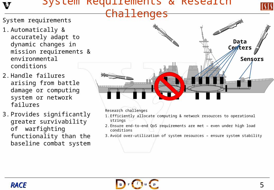
System Requirements & Research ChallengesSystem requirements
1. Automatically & accurately adapt to dynamic changes in mission requirements & environmental conditions
2. Handle failures arising from battle damage or computing system or network failures
3. Provides significantly greater survivability of warfighting functionality than the baseline combat system
Sensors
Data Centers
Research challenges
1. Efficiently allocate computing & network resources to operational strings
2. Ensure end-to-end QoS requirements are met – even under high load conditions
3. Avoid over-utilization of system resources – ensure system stability
6RACERACE
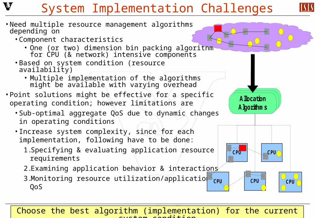
System Implementation Challenges• Need multiple resource management algorithms
depending on • Component characteristics
• One (or two) dimension bin packing algorithm for CPU (& network) intensive components
• Based on system condition (resource availability)• Multiple implementation of the algorithms might be
available with varying overhead• Point solutions might be effective for a specific operating
condition; however limitations are• Sub-optimal aggregate QoS due to dynamic changes
in operating conditions• Increase system complexity, since for each
implementation, following have to be done:
1.Specifying & evaluating application resource requirements
2.Examining application behavior & interactions
3.Monitoring resource utilization/application QoS
Choose the best algorithm (implementation) for the current system condition
CPU
CPU CPU
CPUCPU
Allocation AlgorithmsAllocation AlgorithmsAllocation Algorithms
7RACERACE
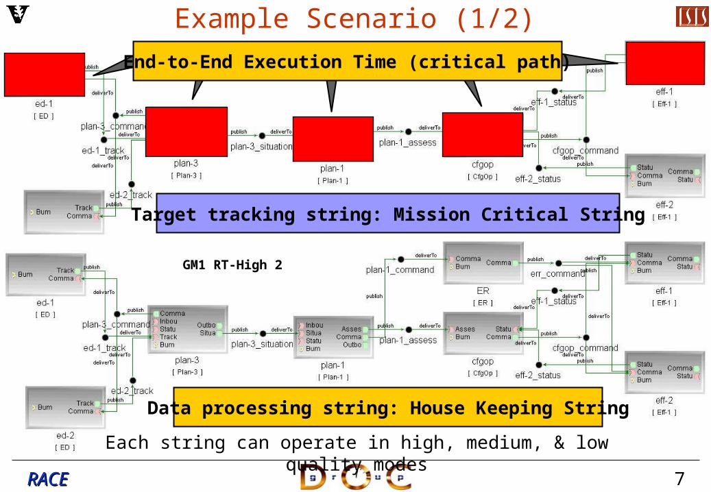
GM1 RT-High 1
Target tracking string: Mission Critical String
GM1 RT-High 2
Data processing string: House Keeping String
Example Scenario (1/2)
Each string can operate in high, medium, & low quality modes
End-to-End Execution Time (critical path)
8RACERACE
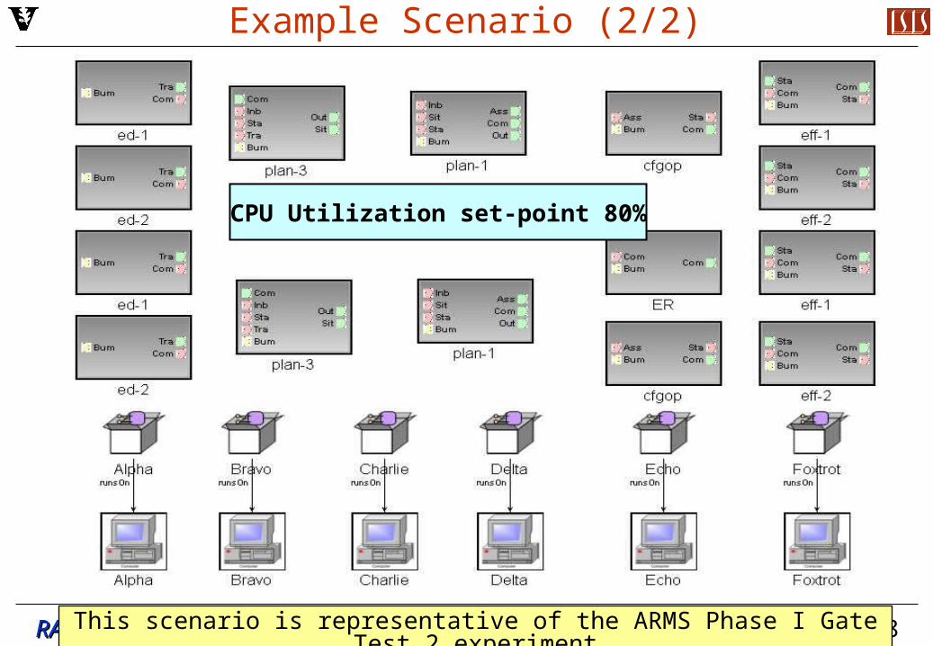
Example Scenario (2/2)
This scenario is representative of the ARMS Phase I Gate Test 2 experiment
CPU Utilization set-point 80%
14RACERACE
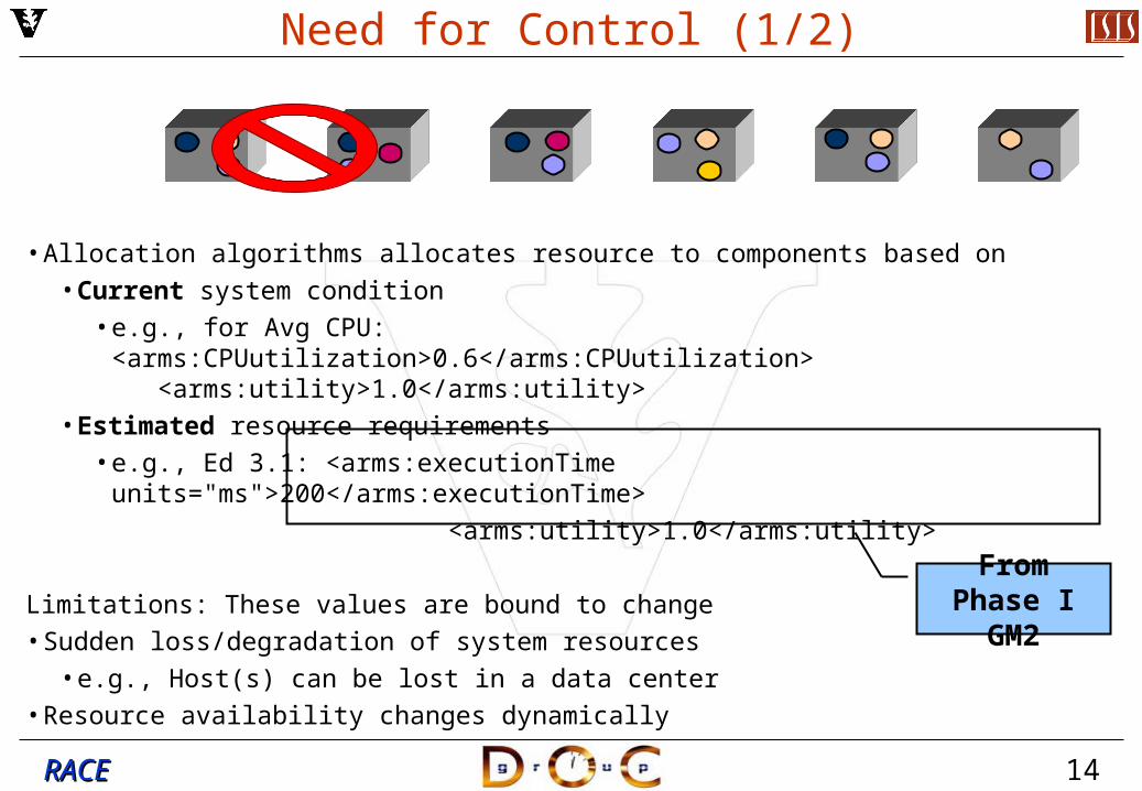
Need for Control (1/2)
• Allocation algorithms allocates resource to components based on • Current system condition
• e.g., for Avg CPU: <arms:CPUutilization>0.6</arms:CPUutilization> <arms:utility>1.0</arms:utility>
• Estimated resource requirements• e.g., Ed 3.1: <arms:executionTime units="ms">200</arms:executionTime>
<arms:utility>1.0</arms:utility>
Limitations: These values are bound to change• Sudden loss/degradation of system resources
• e.g., Host(s) can be lost in a data center• Resource availability changes dynamically
From Phase I GM2
15RACERACE
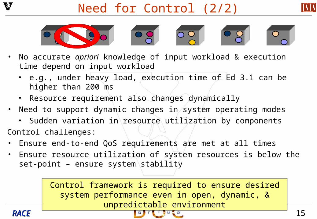
Need for Control (2/2)
• No accurate apriori knowledge of input workload & execution time depend on input workload• e.g., under heavy load, execution time of Ed 3.1 can be higher than 200 ms• Resource requirement also changes dynamically
• Need to support dynamic changes in system operating modes• Sudden variation in resource utilization by components
Control challenges:• Ensure end-to-end QoS requirements are met at all times• Ensure resource utilization of system resources is below the set-point – ensure
system stability
Control framework is required to ensure desired system performance even in open, dynamic, & unpredictable environment
16RACERACE
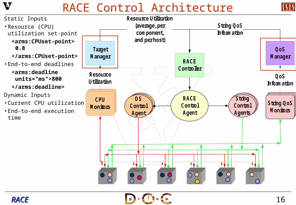
RACE Control ArchitectureStatic Inputs
• Resource (CPU) utilization set-point
<arms:CPUset-point> 0.8
</arms:CPUset-point>
• End-to-end deadlines
<arms:deadline units="ms">800
</arms:deadline>
Dynamic Inputs
• Current CPU utilization
• End-to-end execution time
RACEController
Resource Utilization (average, per component,
and per host)
String QoS Information
Target Manager
CPU Monitors
Resource Utilization
RACE Control Agent
StringControl Agents
QoS Manager
String QoS Monitors
QoS Information
OS Control Agent

17RACERACE
RACE Control Architecture
Processing• Controller, with the
help of Control Agents, modifies the OS priority and/or operational string modes in order to
1.Meet desired application QoS - End-to-end deadline
2.Maintain CPU utilization below set-point
RACEController
Resource Utilization (average, per component,
and per host)
String QoS Information
Target Manager
CPU Monitors
Resource Utilization
RACE Control Agent
StringControl Agents
QoS Manager
String QoS Monitors
QoS Information
OS Control Agent
18RACERACE
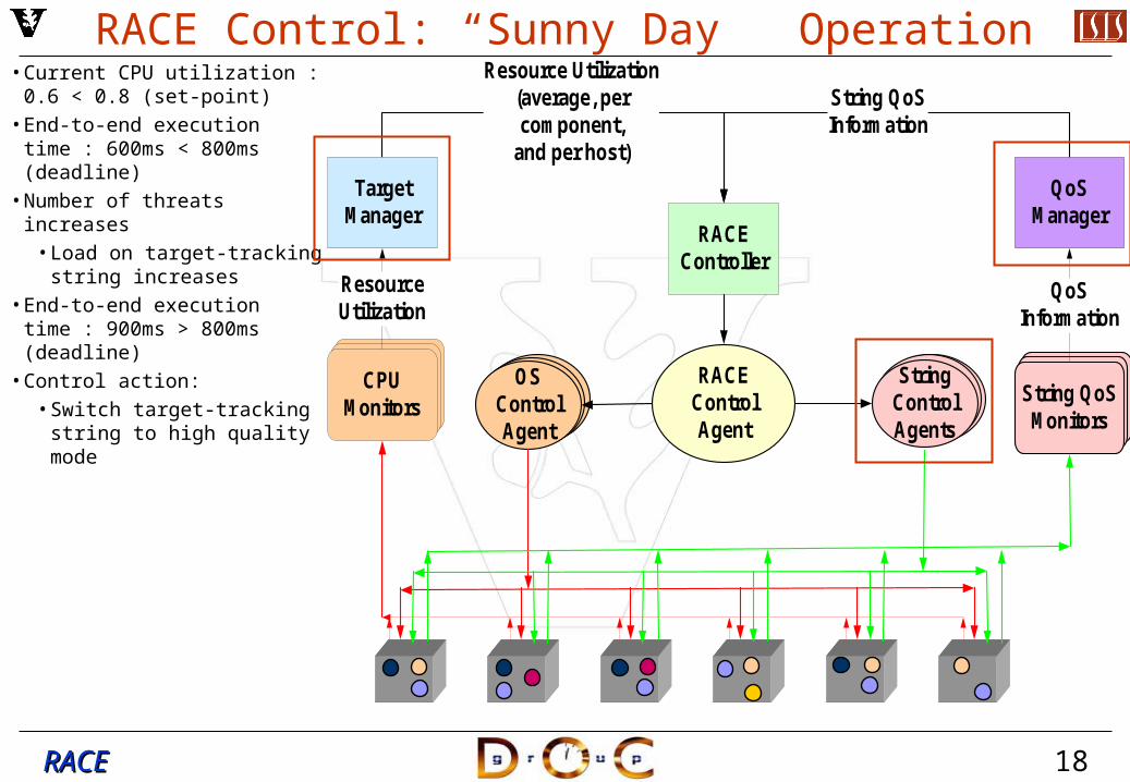
RACE Control: “Sunny Day” Operation• Current CPU utilization : 0.6
< 0.8 (set-point)
• End-to-end execution time : 600ms < 800ms (deadline)
• Number of threats increases
• Load on target-tracking string increases
• End-to-end execution time : 900ms > 800ms (deadline)
• Control action:
• Switch target-tracking string to high quality mode
RACEController
Resource Utilization (average, per component,
and per host)
String QoS Information
Target Manager
CPU Monitors
Resource Utilization
RACE Control Agent
StringControl Agents
QoS Manager
String QoS Monitors
QoS Information
OS Control Agent
19RACERACE
RACEController
Resource Utilization (average, per component,
and per host)
String QoS Information
Target Manager
CPU Monitors
Resource Utilization
RACE Control Agent
StringControl Agents
QoS Manager
String QoS Monitors
QoS Information
OS Control Agent
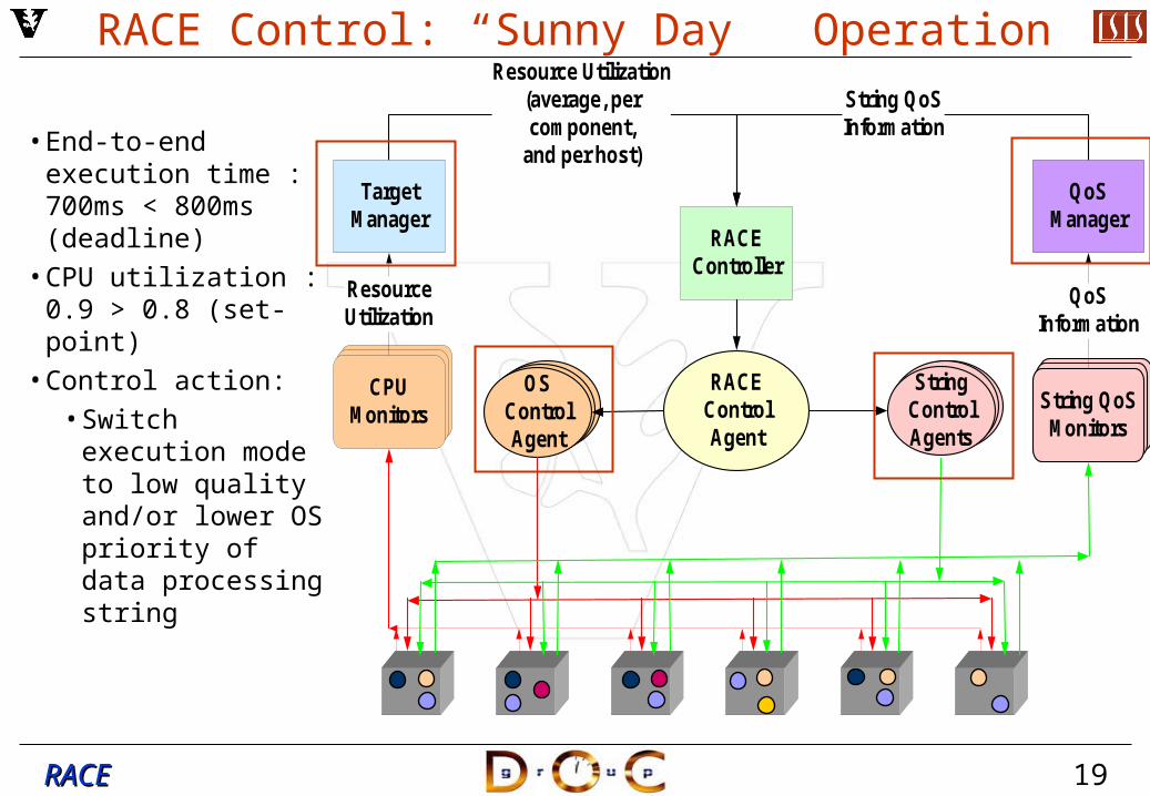
RACE Control: “Sunny Day” Operation
• End-to-end execution time : 700ms < 800ms (deadline)
• CPU utilization : 0.9 > 0.8 (set-point)
• Control action:• Switch execution
mode to low quality and/or lower OS priority of data processing string
20RACERACE
RACEController
Resource Utilization (average, per component,
and per host)
String QoS Information
Target Manager
CPU Monitors
Resource Utilization
RACE Control Agent
StringControl Agents
QoS Manager
String QoS Monitors
QoS Information
OS Control Agent
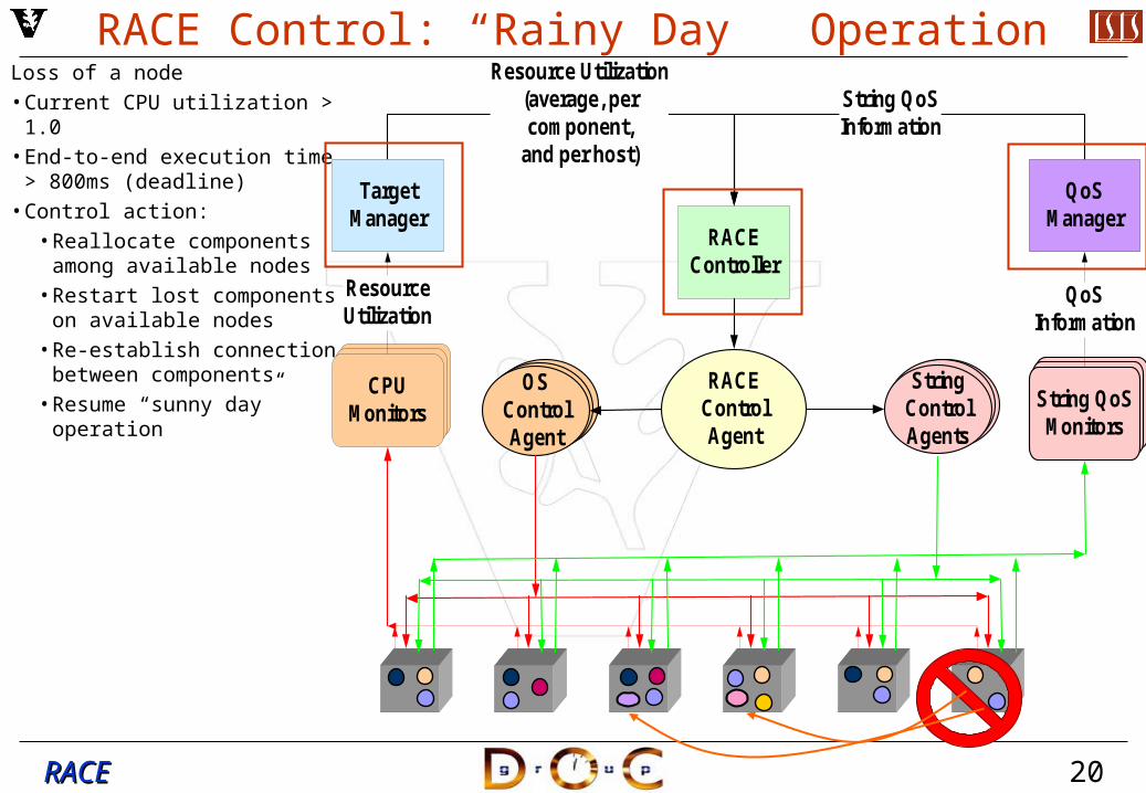
RACE Control: “Rainy Day” OperationLoss of a node• Current CPU utilization > 1.0• End-to-end execution time >
800ms (deadline)• Control action:
• Reallocate components among available nodes
• Restart lost components on available nodes
• Re-establish connection between components
• Resume “sunny day” operation
21RACERACE
CUTS Environment for Emulating DRE Systems• Component Workload Emulator
(CoWorkEr) Utilization Test Suite (CUTS) consists of a test network of CoWorkEr nodes
• Outside the test network is a Benchmark Data Collector (BDC) for collecting test metrics
• Makeup & functionality of a CoWorkEr• CCM assembly constructed from CCM
monolithic components• Can perform CPU operations,
database operations & memory allocations & deallocations
• Can perform background workloads• Can send/receive events to/from other
CoWorkErs to form application strings

22RACERACE
Measuring the Performance of Components with CUTS
Time to transmit an event is measured
Time to process an event is measured
Critical paths can be selected & evaluated to determine if end-to-end QoS deadlines are meet
All data is collected by the Benchmark Data Collector (BDC) & stored in a database for offline evaluation
23RACERACE
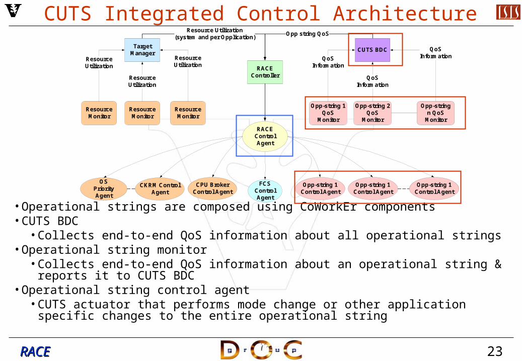
CUTS Integrated Control Architecture
• Operational strings are composed using CoWorkEr components• CUTS BDC
• Collects end-to-end QoS information about all operational strings• Operational string monitor
• Collects end-to-end QoS information about an operational string & reports it to CUTS BDC
• Operational string control agent• CUTS actuator that performs mode change or other application specific changes to
the entire operational string
RACEController
Resource Utilization (system and per Opplication)
Opp string QoS
Target Manager
Resource Monitor
Resource Monitor
Resource Monitor
Resource Utilization
Resource Utilization
Resource Utilization
RACE Control Agent
CKRM Control Agent
FCSControl Agent
CPU Broker Control Agent
Opp-string 1 Control Agent
CUTS BDC
Opp-string 1 QoS
Monitor
QoS Information
QoS Information
QoS Information
OS Priority Agent
Opp-string 2 QoS
Monitor
Opp-string n QoS
Monitor
Opp-string 1 Control Agent
Opp-string 1 Control Agent
24RACERACE
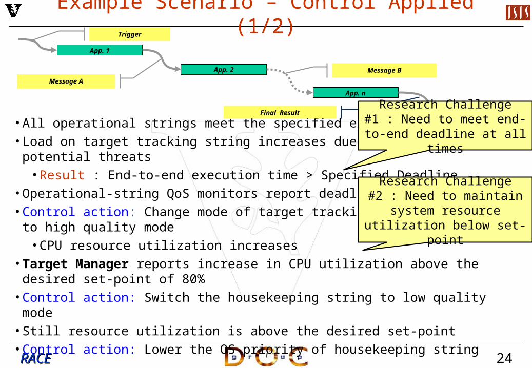
Example Scenario – Control Applied (1/2)
• All operational strings meet the specified execution deadline• Load on target tracking string increases due to increase in potential threats
• Result : End-to-end execution time > Specified Deadline• Operational-string QoS monitors report deadline misses• Control action: Change mode of target tracking string from medium to high quality
mode • CPU resource utilization increases
•Target Manager reports increase in CPU utilization above the desired set-point of 80%
• Control action: Switch the housekeeping string to low quality mode• Still resource utilization is above the desired set-point• Control action: Lower the OS priority of housekeeping string
App. 1
App. 2
App. n
Trigger
Message A
Final Result
Message B
Research Challenge #1 : Need to meet end-to-end
deadline at all times
Research Challenge #2 : Need to maintain system resource utilization below
set-point
25RACERACE
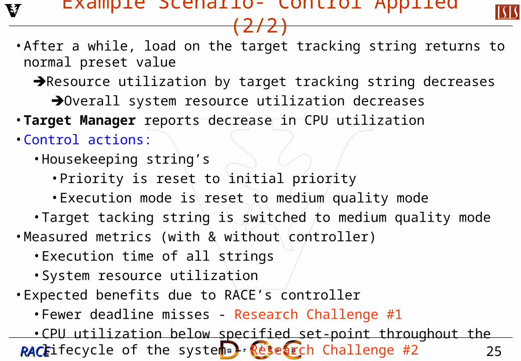
Example Scenario- Control Applied (2/2)
• After a while, load on the target tracking string returns to normal preset value
Resource utilization by target tracking string decreases
Overall system resource utilization decreases•Target Manager reports decrease in CPU utilization • Control actions:
• Housekeeping string’s• Priority is reset to initial priority• Execution mode is reset to medium quality mode
• Target tacking string is switched to medium quality mode• Measured metrics (with & without controller)
• Execution time of all strings• System resource utilization
• Expected benefits due to RACE’s controller• Fewer deadline misses - Research Challenge #1• CPU utilization below specified set-point throughout the lifecycle of the system
– Research Challenge #2
26RACERACE
Current Status of CUTS
• Application strings can be connected by connecting multiple CoWorkEr components to each other, which is done at deployment time
• Events transmitted between CoWorkEr components associate data payload• Combinations of events can be specified, which at as workload
conditions/guards (i.e. workload X may require Event A & B to begin processing)
• Can create background workloads in a CoWorkEr that are triggered periodically & at a user-defined probability & rate, which can emulate non-deterministic, or fault, behavior
• All performance data is pushed to the Benchmark Data Collector & stored in a database of offline data analysis
• End-to-end deadline is analyzed in a critical path, instead of component-to-component deadline
27RACERACE
Assumptions & Required Extensions to CUTS Architecture• Assumptions
• All CoWorkers are in the “critical path” of an operational string• Pull model for data acquisition from individual CoWorkEr that make up the
operational string• One end-to-end data collector per operational string• No logging of performance information – no data base
• Required Extensions• Need to redefine CoWorkEr behavior to include user defined workers that
operate on the payload as well as generate payload• Implement the pull model for data acquisition by the BDC • Perform online end-to-end data analysis • Need to modify CoWorkEr resource utilization
• One thread per event type• Multiple threads per event type

28RACERACE
Plan of Action• Use current Target Manager implementation to provide resource utilization
information• Extend the CUTS to incorporate previously listed extensions• Define necessary interfaces for the controller, WLG BDC, & control agent• Implement simple control algorithm• Integrated WLG Demo!• Write papers• Integrate with other ARMS entities
29RACERACE
EASEL (D)
• Problem Definition• Solution• Benefits & Research Challenges • CONOPS for 2005 demo
• Technologies• Objectives• Workflow
• Roadmap for 2006
30RACERACE
Problem Definition
• Many of the same problems that exist in EASEL(L) also exist in EASEL(D)• However, distributed systems also have their own concerns:
• Geographical dispersion increases complexity• Network behavior can be very unpredictable
• Distributed fault tolerance & security mechanisms may incur significant overhead in distributed deployments compared with local deployments
• Software technologies that enhance system decomposition also complicate system integration by yielding new unresolved challenges, including:
• Lack of tools for composing, configuring & deploying distributed system components on heterogeneous platforms
• Distributed resource allocation & control policies (e.g. first-fit decreasing) often leads to less-than-optimal performance
• Contention for resources shared by distributed components• Need for global synchronization mechanisms
Deployment & execution architectures are often thought of as second-class concerns, but they are first-class problems!
31RACERACE
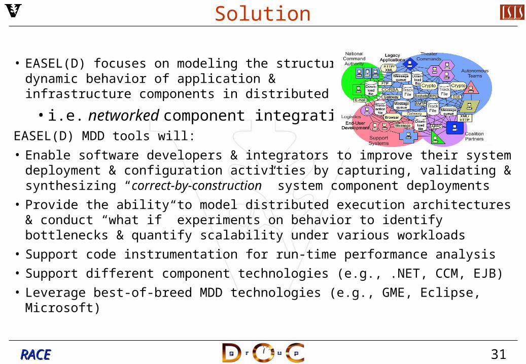
Solution
• EASEL(D) focuses on modeling the structural & dynamic behavior of application & infrastructure components in distributed systems
• i.e. networked component integrationEASEL(D) MDD tools will:
• Enable software developers & integrators to improve their system deployment & configuration activities by capturing, validating & synthesizing “correct-by-construction” system component deployments
• Provide the ability to model distributed execution architectures & conduct “what if” experiments on behavior to identify bottlenecks & quantify scalability under various workloads
• Support code instrumentation for run-time performance analysis
• Support different component technologies (e.g., .NET, CCM, EJB)
• Leverage best-of-breed MDD technologies (e.g., GME, Eclipse, Microsoft)
32RACERACE
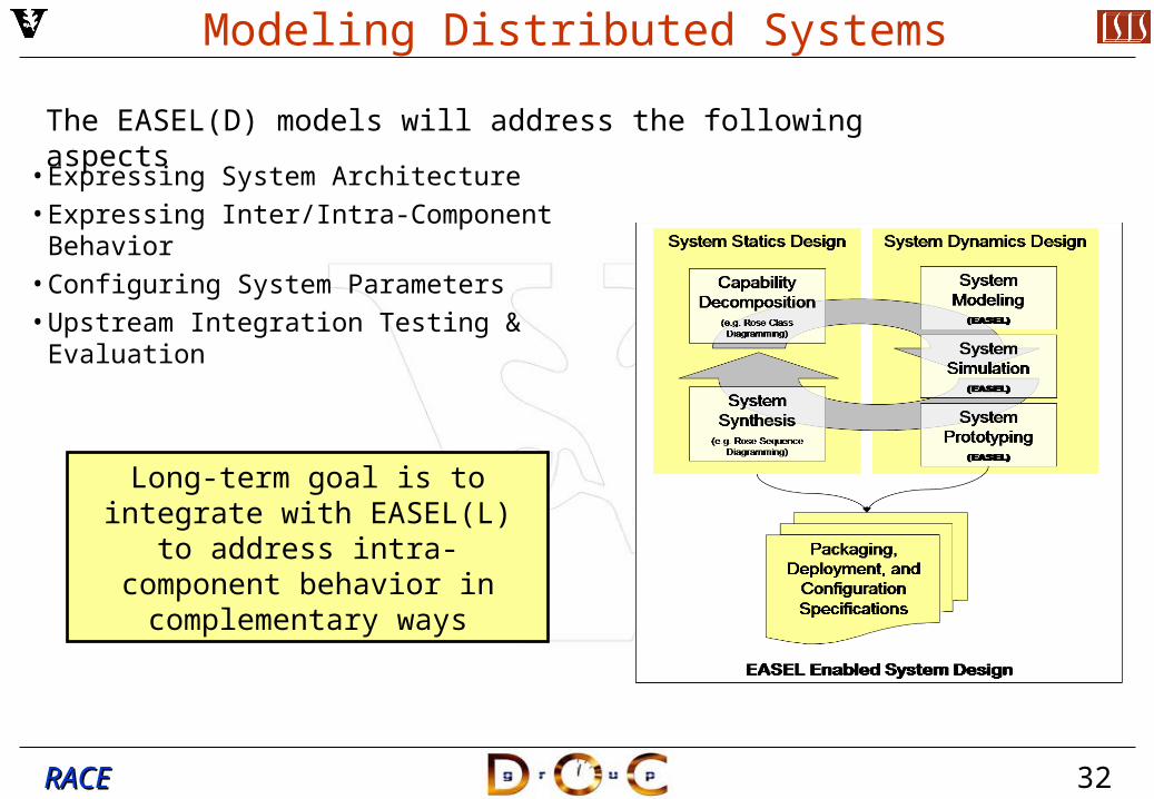
Modeling Distributed Systems
• Expressing System Architecture• Expressing Inter/Intra-Component Behavior• Configuring System Parameters• Upstream Integration Testing & Evaluation
The EASEL(D) models will address the following aspects
Long-term goal is to integrate with EASEL(L) to address intra-
component behavior in complementary ways
33RACERACE
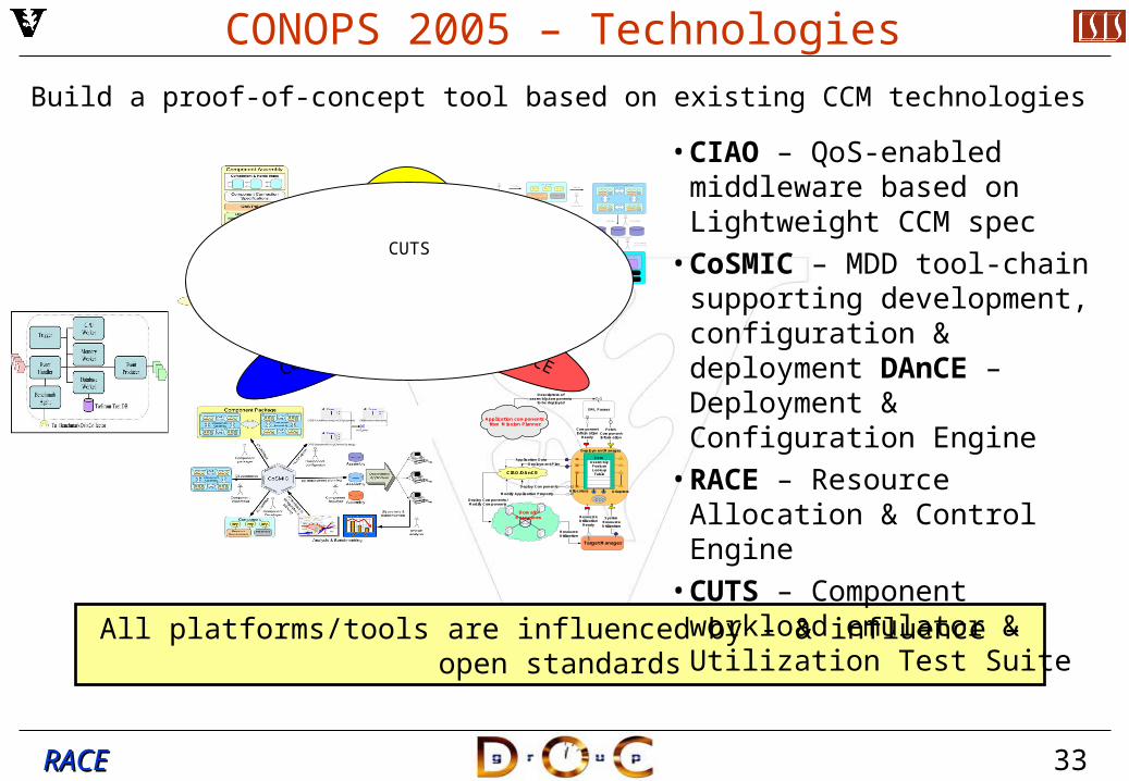
CONOPS 2005 – Technologies
Build a proof-of-concept tool based on existing CCM technologies
All platforms/tools are influenced by - & influence – open standards
Application components from Mission Planner
Descriptors of assembly/components
to be deployed
CIAO/DAnCE
Component Information
Ready
Fetch Component Information
Deployment Plan
Deploy Components
Application Data
Modify Application Property
ResourceUtilization
Ready
SystemResourceUtilization
XML Parser
ResourceUtilization
Deploy Components/Modify Components
Domain Resources
Target Manager
Deployment Manager
CoreAssembly FeatureLookupTable
Allocators Adapters
CIAO
DAnCE
Domain
Access Resources
Assembler
Assembler
Planner
Domain Administrator
Specifies
CreatesComponent
ResourceRequirements
Impl Impl Impl
Properties
COMPONENT REPOSITORY
QoS Specs
Configurations
Dependencies
Developer
CreatesComponent Assembly
ComponentComponent
ComponentComponent
Creates Packager
Repository Administrator
Component Packages
Configures
Desktop Printer Laptop computer
Ethernet Bridge
Firewall
Creates
Executor
Deployment PlanUses
Deploys
RACECoSMIC
CUTS
• CIAO – QoS-enabled middleware based on Lightweight CCM spec
• CoSMIC – MDD tool-chain supporting development, configuration & deployment DAnCE – Deployment & Configuration Engine
• RACE – Resource Allocation & Control Engine
• CUTS – Component workload emulator & Utilization Test Suite
34RACERACE
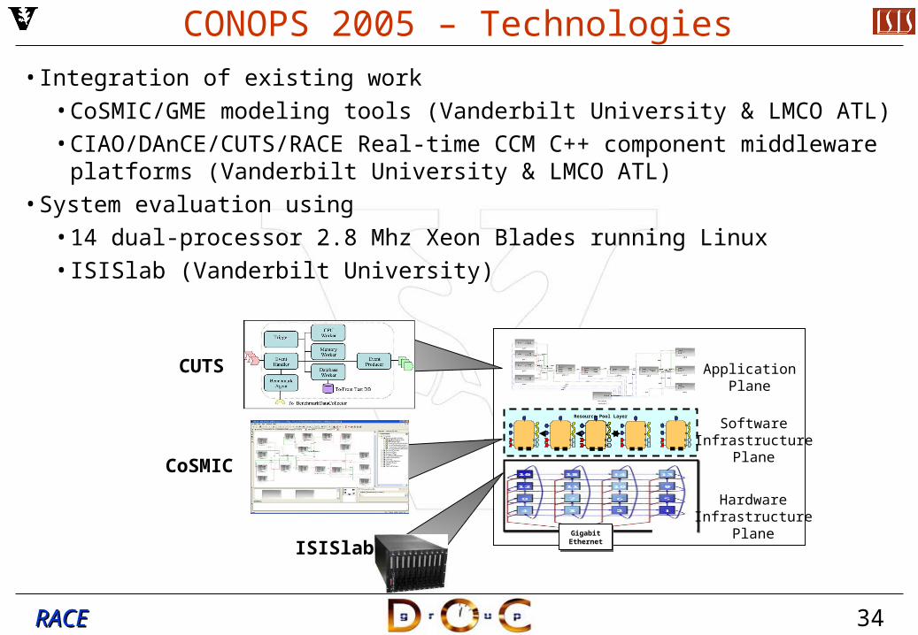
CONOPS 2005 – Technologies• Integration of existing work
• CoSMIC/GME modeling tools (Vanderbilt University & LMCO ATL)• CIAO/DAnCE/CUTS/RACE Real-time CCM C++ component middleware
platforms (Vanderbilt University & LMCO ATL)• System evaluation using
• 14 dual-processor 2.8 Mhz Xeon Blades running Linux• ISISlab (Vanderbilt University)
Gigabit EthernetGigabit
Ethernet
Resource Pool Layer
ApplicationPlane
SoftwareInfrastructure
Plane
HardwareInfrastructure
Plane
CUTS
CoSMIC
ISISlab

35RACERACE
CONOPS 2005 – Objectives
• Use 2005 as an exploratory phase for 2006 planning• Use the prototype EASEL(D) tool to:
• Construct a PICML model for representative application• e.g., component interfaces, component logical interconnections, target
domain nodes, static deployment planning• Develop a CUTS-based execution emulation architecture
• Defines the mapping of emulated components to logical & physical distributed computing resources
• Demonstrate the MDD tool-based design & experimentation process & its flow down into the CIAO/DAnCE/RACE middleware platform
• Demonstrate “what if” performance speculation for a given design by manual analysis using LMCO ATL scheduling tools
• Augment & validate speculation by actual run-time performance analysis using MDD-based tools & middleware platforms
36RACERACE
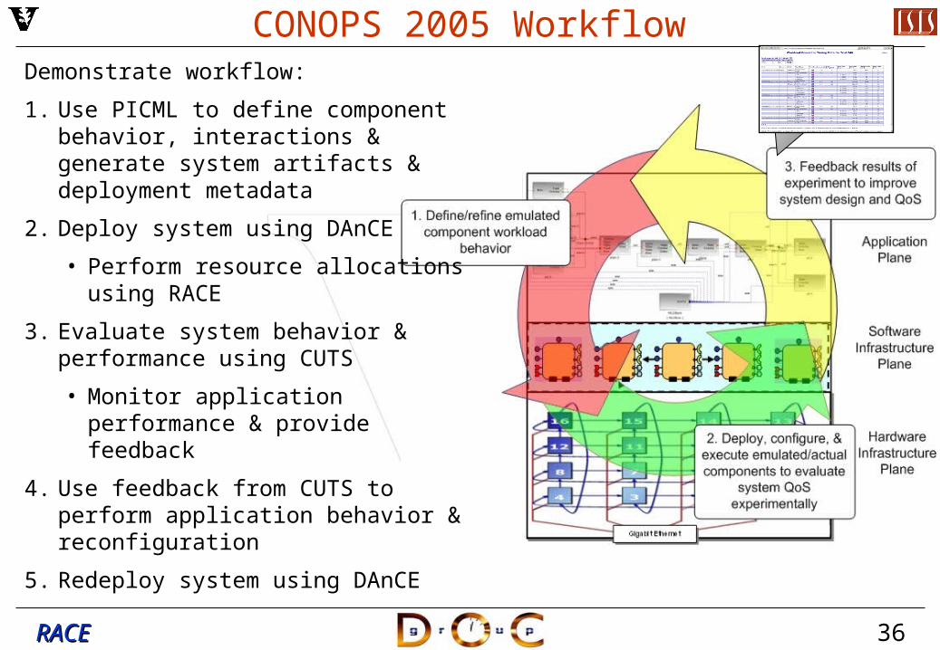
CONOPS 2005 WorkflowDemonstrate workflow:
1. Use PICML to define component behavior, interactions & generate system artifacts & deployment metadata
2. Deploy system using DAnCE
• Perform resource allocations using RACE
3. Evaluate system behavior & performance using CUTS
• Monitor application performance & provide feedback
4. Use feedback from CUTS to perform application behavior & reconfiguration
5. Redeploy system using DAnCE
37RACERACE
Model Distributed Components & Interconnections
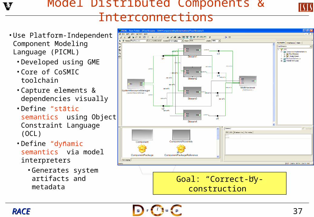
• Use Platform-Independent Component Modeling Language (PICML)• Developed using GME• Core of CoSMIC toolchain• Capture elements &
dependencies visually• Define “static semantics”
using Object Constraint Language (OCL)
• Define “dynamic semantics” via model interpreters
• Generates system artifacts and metadata Goal: “Correct-by-construction”
38RACERACE
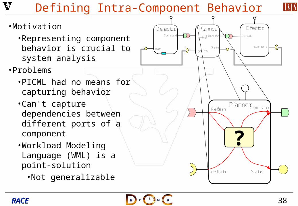
Defining Intra-Component Behavior
• Motivation• Representing component
behavior is crucial to system analysis
• Problems• PICML had no means for
capturing behavior• Can't capture dependencies
between different ports of a component
• Workload Modeling Language (WML) is a point-solution
• Not generalizable
DetectorCommand
Data
Planner
Status
RefreshCommand
Effector
Refresh
GetStatusgetData
PlannerRefresh Command
getData Status
?
39RACERACE
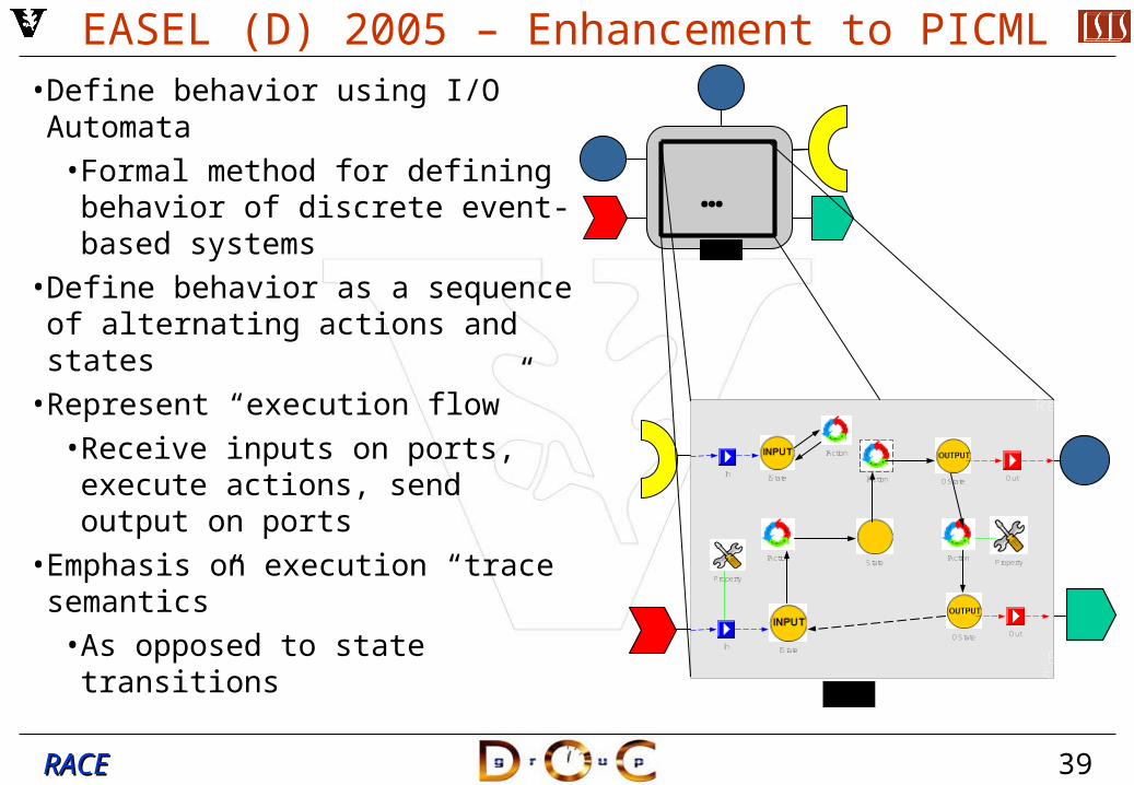
EASEL (D) 2005 – Enhancement to PICML• Define behavior using I/O
Automata• Formal method for defining
behavior of discrete event-based systems
• Define behavior as a sequence of alternating actions and states
• Represent “execution flow”• Receive inputs on ports,
execute actions, send output on ports
• Emphasis on execution “trace semantics”
• As opposed to state transitions
…
ReceptacleFacet
Event Sink
EventSource
Attribute
In IState
IAction
OutOState
Property
State
IAction
OState
IAction
Out
InIState
IAction
Property
40RACERACE
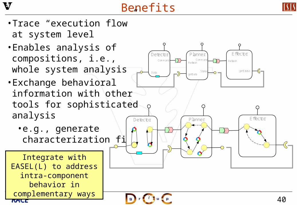
Benefits• Trace “execution flow” at
system level• Enables analysis of
compositions, i.e., whole system analysis
• Exchange behavioral information with other tools for sophisticated analysis
• e.g., generate characterization file
DetectorCommand
Data
Planner
Status
RefreshCommand
Effector
Refresh
getStatusgetData
Detector Planner Effector
Integrate with EASEL(L) to address intra-component
behavior in complementary ways
41RACERACE
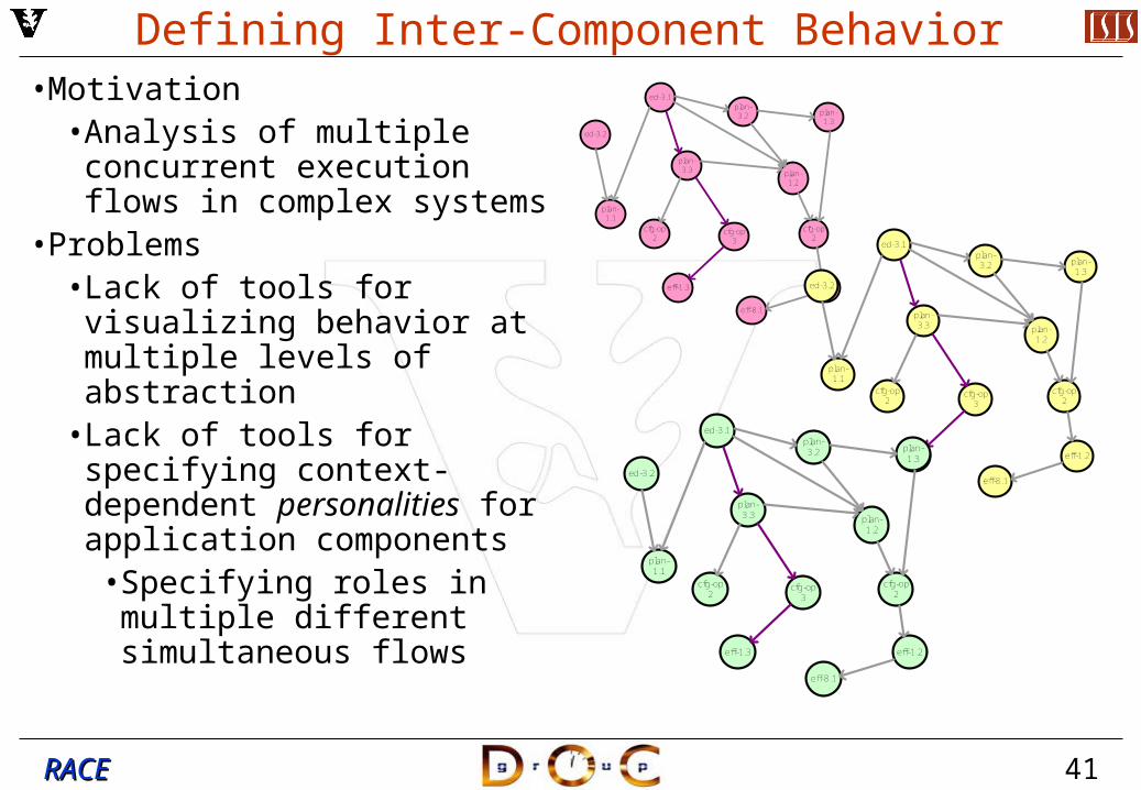
Defining Inter-Component Behavior• Motivation
• Analysis of multiple concurrent execution flows in complex systems
• Problems• Lack of tools for visualizing
behavior at multiple levels of abstraction
• Lack of tools for specifying context-dependent personalities for application components
• Specifying roles in multiple different simultaneous flows
ed-3.1
plan-3.3
cfg-op 3
eff-1.3
plan-1.1
plan-3.2
plan-1.2
cfg-op 2
cfg-op 2
ed-3.2
plan-1.3
eff-1.2
eff-8.1
ed-3.1
plan-3.3
cfg-op 3
eff-1.3
plan-1.1
plan-3.2
plan-1.2
cfg-op 2
cfg-op 2
ed-3.2
plan-1.3
eff-1.2
eff-8.1
ed-3.1
plan-3.3
cfg-op 3
eff-1.3
plan-1.1
plan-3.2
plan-1.2
cfg-op 2
cfg-op 2
ed-3.2
plan-1.3
eff-1.2
eff-8.1

42RACERACE
EASEL (D) 2005 – Enhancement to PICML• Path Diagram
• Build Graph with (component, port) tuple as vertices & inter-component connections as edges
• Generate “execution flows”, i.e., path diagrams, using standard graph algorithms
• Allow assignment of properties to each path
• Deadlines• Criticality
• Enables system analysis at multiple levels of detail
Detector-command
Effector-Refresh
Planner-Command
Detector-Data
Planner-getData
Planner-Refresh
Effector-getStatus
Planner-Status
DetectorCommand
Data
Planner
Status
RefreshCommand
Effector
Refresh
getStatusgetData
43RACERACE
ed-3.1
plan-3.3
cfg-op 3
eff-1.3
plan-1.1
plan-3.2
plan-1.2
cfg-op 2
cfg-op 2
ed-3.2
plan-1.3
eff-1.2
eff-8.1
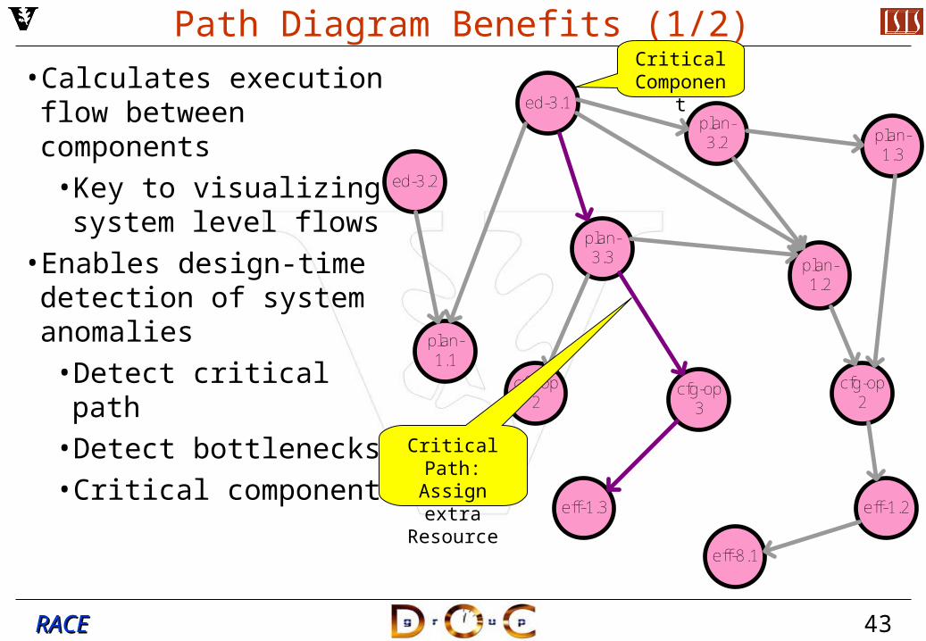
Path Diagram Benefits (1/2)
• Calculates execution flow between components
• Key to visualizing system level flows
• Enables design-time detection of system anomalies
• Detect critical path• Detect bottlenecks• Critical components
Critical Path: Assign extra
Resource
Critical Component
44RACERACE
ed-3.1
plan-3.3
cfg-op 3
eff-1.3
plan-1.1
plan-3.2
plan-1.2
cfg-op 2
cfg-op 2
ed-3.2
plan-1.3
eff-1.2
eff-8.1
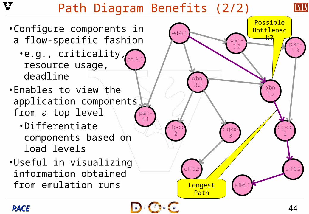
Path Diagram Benefits (2/2)
• Configure components in a flow-specific fashion
• e.g., criticality, resource usage, deadline
• Enables to view the application components from a top level
• Differentiate components based on load levels
• Useful in visualizing information obtained from emulation runs
Longest Path
Possible Bottleneck?
45RACERACE
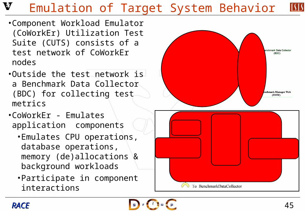
Emulation of Target System Behavior• Component Workload Emulator
(CoWorkEr) Utilization Test Suite (CUTS) consists of a test network of CoWorkEr nodes
• Outside the test network is a Benchmark Data Collector (BDC) for collecting test metrics
• CoWorkEr - Emulates application components
• Emulates CPU operations, database operations, memory (de)allocations & background workloads
• Participate in component interactions
46RACERACE
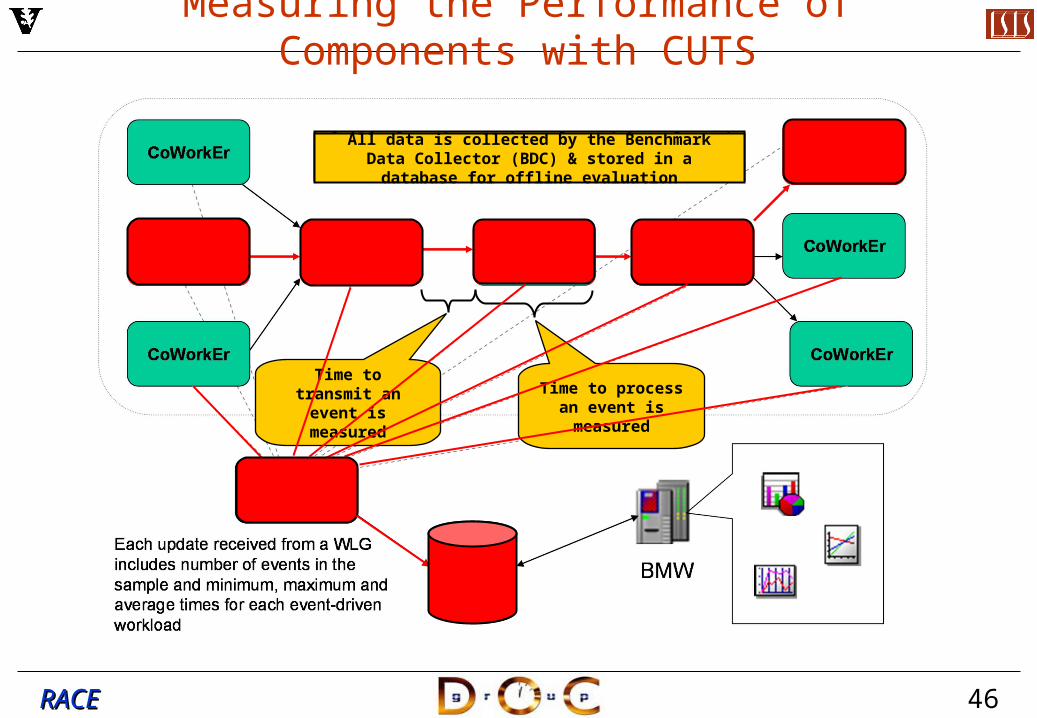
Measuring the Performance of Components with CUTS
Time to transmit an event is measured
Time to process an event is measured
Critical paths can be selected & evaluated to determine if end-to-end QoS deadlines are meet
All data is collected by the Benchmark Data Collector (BDC) & stored in a database for offline evaluation
47RACERACE
CONOPS 2005 – Benefits
• More effective reuse of distributable components on emerging & more effective reuse legacy platforms
• LMCO organizations can maintain coherent & correct coupling of design choices across iterative software lifecycle
• Reduced cost & time-to-market by alleviating numerous integration problems that arise today
• e.g., inherent & accidental complexities in developing large-scale software in LMCO’s multi-organization & iterative development processes w/ legacy system integration & reuse
• Improved performance through quantitative evaluation of distributed system design- & run-time space
• Improved quality & reliability through enhanced understanding of concurrent execution behavior of distributed components in integrated systems early in the lifecycle
MDD tools will decrease software defect rates, enhance performance, & automate tracing from logical design artifacts to
deployed software
48RACERACE
Research Challenges
Distributed system deployment & execution architectures are:• Hard to simulate accurately due to inherent complexities
• e.g., managing shared resources in distributed systems under various time/space constraints
• Closely coupled to the underlying hardware/software infrastructure & therefore affected directly by changes in platforms
• e.g., need to support emerging & legacy platform technologies• Complex, varied & continuously evolving
• e.g., middleware, component technology, programming languages, operating systems, networks, hardware
• Largely designed & evaluated using manual and/or ad hoc techniques that are tedious, error-prone & non-scalable
• Existing solutions often have no formal basis for validating & verifying that the configured software will deliver the performance requirements throughout a distributed system
49RACERACE
EASEL(D) 2006 Roadmap
• Enrich model of distributed deployment & execution architecture• Additional MDD tools for deployment & configuration
• Enhance CUTS modeling & analysis capabilities• e.g., specification of performance properties, place constraints on resource
availability & usage, permit specification of adaptive behavior for dynamic performance evaluation
• Broaden support for multi-platform run-time analysis• e.g., Windows XP, Linux(es), & Solaris operating systems
• Add support for EJB & .NET • e.g., enable applications to write in C++, C#, or Java
• Align conops & technologies with EASEL(L)• Add support for other COTS MDD tools, as available
• e.g., Eclipse Graphical Modeling Framework (GMF) & Microsoft Software Factory DSL tools
• Demonstrate MDD tools on IS&S-related application & code base
50RACERACE
Questions?