owner s manual series 1 hard drive - ameri-shred...
TRANSCRIPT

Service Department: 888.270.6879
AMS-150HD/ AMS-150HD-SSD/ AMS-150-SSD AMS-300HD/ AMS-300HD-SSD/ AMS-300-SSD
OWNER’S MANUAL SERIES 1 HARD DRIVE
NOTICE: The information contained within this manual is correct at time of printing, but due to the continuing development of prod ucts,
changes in specifications are inevitable. Ameri-Shred reserves the right to implement such changes without prior notice.

2 Service Department: 888.270.6879
UNLOADING/UNPACKING ......................................................................................................................... 3
ELECTRICAL INSTALLATION ........................................................................................................................ 4
NAMEPLATE (LOG SHREDDER SPECIFICS) ................................................................................................... 4
SAFETY WARNINGS .................................................................................................................................... 5
SHREDDER OPERATION .............................................................................................................................. 6
START UP PROCEDURE ............................................................................................................................... 7
SERVER DRIVE JAM WARNING ................................................................................................................... 8
CLEARING A JAM ........................................................................................................................................ 9
SHUT DOWN PROCEDURE ......................................................................................................................... 9
CURRENT RELAY ADJUSTMENT ................................................................................................................... 9
TROUBLESHOOTING ................................................................................................................................... 10
MAINTENANCE ... ....................................................................................................................................... 11-12
MAINTENANCE CHECKLISTS . ...................................................................................................................... 13-16
CONVEYOR BELT ADJUSTMENT. ................................................................................................................. 17
PARTS LISTS
CUTTER ASSEMBLY - HD-SSD MODELS ................................................................................................. 18-19
CUTTER ASSEMBLY - HD MODELS ........................................................................................................ 20-21
CUTTER ASSEMBLY - SSD MODELS ....................................................................................................... 22
OUTPUT CONVEYOR ........................................................................................................................... 23
ELECTRICAL DIAGRAMS - 1.5 HP MODELS .......................................................................................... 24-29
ELECTRICAL DIAGRAMS - 3 HP MODELS ............................................................................................. 30-33
TABLE OF CONTENTS

3 Service Department: 888.270.6879
Your new Ameri-Shred shredder has been secured to a pallet for shipping. Please inspect equipment immediately for shipping damage.
Using a lift truck with a minimum capacity of 1500 lbs., remove the machine from the carrier and transport to operation site. Remove pallet and discard responsibly.
Unpack the shredder and inspect it for any obvious damage. Note any damage on the bill of lading and contact the shipping party immediately.
Ameri-Shred hard drive shredders are equipped with casters for ease of handling.
Unlock cabinet doors and visually inspect the internal cabinet to check for any internal damage. Photograph any damage and contact the shipping party immediately.
After inspection, close and relock cabinet doors.
If the optional modular conveyor was purchased, unpack and inspect it for any damage.
After shredder is in position, remove the four bolts that hold the access panel on the back of the shredder.
Go to the front of the shredder, open the access door beneath the cutting chamber and remove the two bolts that are partially threaded in holes in the side plates.
Move the modular conveyor to the back of the shredder and slide it into the access panel opening. Plug it into the provided receptacle.
Go to the front of the shredder and replace the two bolts through the channel that is on the conveyor to secure the conveyor to the shredder. NOTE: Series 1 Hard Drive Shredders are top heavy, which results in a tipping hazard. Always use care when moving the shredder and stay clear of it in the event of a tip. The shredder is too heavy to stop mid way, and it can cause serious injury. Give wide berth if it tips over and ensure that it will not come in contact with any body parts. The potential for tipping is increased significantly on uneven surfaces, particularly on vertical moves. It is imperative that the shredder is secured in place prior to using a lift-gate, fork truck, etc. Secure the shredder with straps, holders, etc. and then move out of harm’s way. The brakes on the shredder’s casters will not secure the shredder during vertical movement.
UNLOADING/UNPACKING
Thank you for purchasing an Ameri-Shred shredder. Our shredders are manufactured in the United States by skilled craftsmen. They are designed with the operator in mind for both ease of operation and maintenance. Ameri-Shred requests that each operator read and familiarize themselves with this manual before operating the machine. Series 1 Hard Drive Shredders are designed to shred hard drives and other electronic media into unusable particles ensuring the contained information is rendered useless. Ameri-Shred believes in using the highest quality components in each of our industrial shredders. This manual includes safety tips, operating instructions, preventative maintenance, lubrication schedules, and trouble shooting information. Please contact our service department at 888-270-6879 with any questions.

4 Service Department: 888.270.6879
All electrical installation and service must be accomplished by a qualified electrician. Follow all national and local electrical codes and ordinances.
“WARNING” LOCK POWER IN OFF POSITION
All internal wiring has been factory installed and tested prior to shipping. Electrical installation consists of providing adequate machine power only.
Check building service to ensure the correct voltage is available and that those current requirements can be met according to nameplate located on the rear panel of the machine. Record the nameplate information in the space below.
Install receptacle (provided on 3-phase models only) to properly protect building’s circuit. Select appropriate wire size and current protection to accommodate current requirements as shown on nameplate. Plug in power cable.
Clear all personnel from machine area. Ensure machine is clean and no tools, rags, or debris have been left on or near cutters or drive mechanism.
Turn building service drop power on. Check voltage at installed receptacle.
Ensure area is clear. Turn key switch to the ON position. Jog reverse. Check for proper motor rotation. If running in reverse, unplug power cable. Check that power is OFF with voltage meter at panel. Remove any two power wires from the motor starter, reverse them, and reconnect.
Clear area, turn on power and recheck motor rotation.
Electrical installation is complete.
Replace all guards.
ELECTRICAL INSTALLATION
MODEL NO. ___________________________________
________________ HORSEPOWER
SERIAL NUMBER ______________________________
_______________ JOB NUMBER
________________ VOLTAGE _______________ PHASE
__________ CYCLE A.C.
___________________ AMPS SERVICE DEPARTMENT: 888.270.6879
NAMEPLATE - LOG YOUR SHREDDER SPECIFICS HERE

5 Service Department: 888.270.6879
Read and understand instruction manual and be aware of all warning stickers.
Make sure that ALL guards and access panels are in place at all times, EXCEPT when the power is locked off for maintenance work or cleaning.
ALWAYS know where emergency stop buttons are located.
ALWAYS know, or have quick access to, emergency phone numbers.
ALWAYS ensure that ALL maintenance and operating personnel read and understand this manual.
ALWAYS have a standard break-in time for a new operator. A minimum of two hours suggested.
ALWAYS wear safety glasses when operating shredder.
ALWAYS “lock out” power at the disconnect when shredder is not in use, when servicing shredder, or when performing routine shredder maintenance—including cleaning.
ALWAYS use correct cutting chamber and ALWAYS use only one at a time.
NEVER operate this or any other machine while under the influence of drugs, alcohol, or medications.
NEVER wear loose fitting clothing, ties, or jewelry while in the vicinity of this shredder.
NEVER allow long hair to be worn in the vicinity of the machine without use of a protective hair net.
NEVER place any part of your body in or on any part of this machine while in operation.
NEVER allow tools, rags, lunch pails, or debris to be placed on the input conveyor or on top of the machine.
NEVER change machine direction without first allowing machine to come to a complete stop.
NEVER allow other personnel within ten feet of this machine while in operation.
NEVER remove guards, perform maintenance, or clear jam-up debris without first locking out power disconnect.
NEVER allow horseplay around machine.
NEVER remove debris from cutter heads while power is on.
NEVER attempt to remove debris from input chute after material has begun to move toward cutter head.
NEVER hold forward button in the depressed position.
SAFETY WARNINGS

6 Service Department: 888.270.6879
DUAL INFEED SLOTS: HD-SSD MODELS
SSD = SOLID STATE DRIVES
SHREDDER OPERATION
CONTROL PANEL
Key Switch
Power Light
Forward
Reverse
E-Stop
INFEED SLOT OPTIONAL OUTPUT
CONVEYOR
HDD = HARD DISK DRIVES

7 Service Department: 888.270.6879
PRE-START UP PROCEDURE
Familiarize yourself with all controls and button locations.
Ensure that all guards and covers are in place.
Ensure the area is clean.
Check input area for debris, discarded tools, etc.
START UP Plug power cable into installed receptacle. Turn key switch ON. Depress momentarily the FORWARD pushbutton. Cutters will begin to rotate and the output conveyor will begin to run forward. To stop machine at any time depress the red STOP pushbutton. For emergency situations the STOP pushbutton may be depressed at any time. For normal stop situations, wait for input chute to empty itself of all shredded material before depressing STOP button. Begin feeding drives one at a time by dropping them into the infeed slot. It is recommended that during the familiarizing period the operator should proceed slowly. After several hours experience the operator may wish to increase the speed and frequency at which they feed the drives. The operator will soon be able to judge the efficiency of the operation and feed material accordingly. It is nearly inevitable that during this learning process the machine will jam. A jam condition will automatically turn off the machine just as if the operator had depressed the STOP button. This is normal.
PRE-START UP PROCEDURE
HD models have 1.5” or 3/4” wide cutters. They can shred solid state drives, but not to a secure particle size. SSD models have 3/8” wide cutters. They cannot shred hard disc drives, which require much wider cutters. HD-SSD models use two separate cutter heads to allow you to destroy both magnetic hard drives as well as electronic media in the same shredder. Use the HDD side for hard disc drives and the SSD side for solid state drives, CD’s, flash drives, floppy discs, etc. WARNING: It is extremely important that rotational hard drives are shred ONLY on the HDD side. Shredding or attempting to use the SSD side will likely result in cutter damage and will void the warranty. Only one feed slot can be used at a time.
SHREDDER DIFFERENCES - HD, SSD & HD-SSD MODELS
START UP PROCEDURE

8 Service Department: 888.270.6879
MATERIAL TESTED: 1” Hard Drives: One per feed approximately every 20 seconds Notebook Drive: Three per feed approximately every 20 seconds DLT Tapes: One per feed approximately every 20 seconds WARNING - UNLIKE SOLID STATE, SOME ROTATIONAL HARD DRIVES ARE CONSTRUCTED IN A WAY THAT MAY WARRANT EXTRA ATTENTION. Listed below are some 1” Hard Drives that may cause jamming. Drives that have thick steel parts. These steel parts may need to be removed prior to shredding in order to prevent jamming. REMINDER: Use HDD side only on HD-SSD models.
SERVER DRIVE JAM WARNING
Drives with multiple steel plates covering platters. These plates may need to be removed prior to shredding to prevent jamming.

9 Service Department: 888.270.6879
Should a jam occur, the machine will turn itself off. Ensure that all personnel are clear of both the input chute and the cutter head. Momentarily depress the yellow REVERSE pushbutton. This will cause the cutters to run backwards for as long as the REVERSE pushbutton remains depressed. Release the REVERSE pushbutton. The machine will come to a stop. After the machine has completely stopped, press the FORWARD button and retry to shred material. Repeat up to one more time. If machine jams again, reverse shredder, Lock Out Power, unlock the cutter-head access door and manually remove offending material. Do not attempt to re-shred this material without disassembling it first. Restart machine in the forward direction to resume operation. NEVER hold the forward button in the depressed position, as damage to the machine and the electrical system could occur. NEVER force the shredder to shred something that is too large or dense for its horsepower. Indicators include, but are not limited to, repeated jamming, an inappropriate sound, smell, shaking, etc. This can result in shredder damage and void the warranty. Instead, stop shredding immediately and set the media aside for a different means of destruction.
CLEARING A JAM
Allow input chute and output conveyor, if provided, to clear all material before shut down.
Depress red STOP pushbutton. Remove power cable from receptacle.
Clean any remaining debris from the machine and from the immediate area.
Clear any shredded debris from cutter area.
NOTE: Press the STOP button before making any changes to the current relay and unplug the machine. Adjusting the knob clockwise will increase the amount of current the machine can draw before jamming. Adjustments need to be made in small increments, one line at a time. If the shredder no longer shuts down during a jam but you hear the motor humming, then the threshold/value knob needs to be turned counterclockwise so that the shredder stops prior to a jam. You will have one of the two current relay’s shown here. Adjust the threshold knob on the orange one and the value knob on the white.
SHUT DOWN PROCEDURE
CURRENT RELAY ADJUSTMENT
Adjust Threshold
Adjust Value
10 Service Department: 888.270.6879
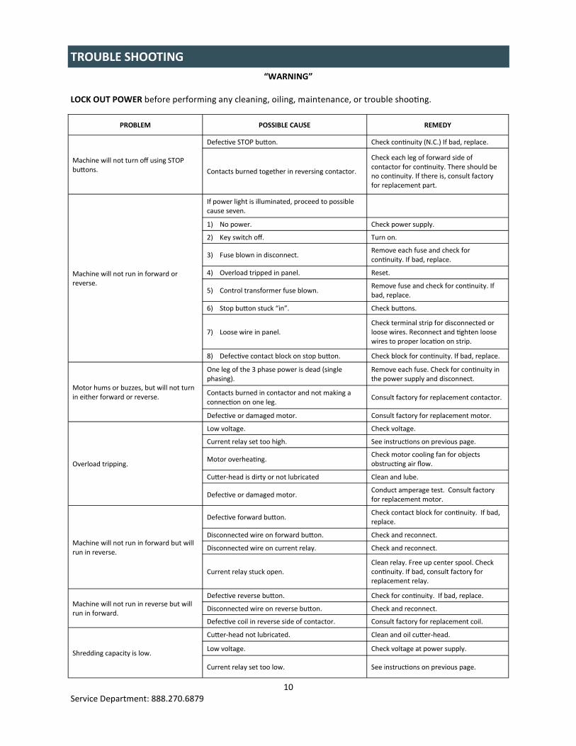
“WARNING”
LOCK OUT POWER before performing any cleaning, oiling, maintenance, or trouble shooting.
TROUBLE SHOOTING
PROBLEM POSSIBLE CAUSE REMEDY
Defective STOP button. Check continuity (N.C.) If bad, replace.
Machine will not turn off using STOP buttons. Contacts burned together in reversing contactor.
Check each leg of forward side of contactor for continuity. There should be no continuity. If there is, consult factory for replacement part.
Machine will not run in forward or reverse.
If power light is illuminated, proceed to possible cause seven.
1) No power. Check power supply.
2) Key switch off. Turn on.
3) Fuse blown in disconnect. Remove each fuse and check for continuity. If bad, replace.
4) Overload tripped in panel. Reset.
5) Control transformer fuse blown. Remove fuse and check for continuity. If bad, replace.
6) Stop button stuck “in”. Check buttons.
7) Loose wire in panel. Check terminal strip for disconnected or loose wires. Reconnect and tighten loose wires to proper location on strip.
8) Defective contact block on stop button. Check block for continuity. If bad, replace.
Motor hums or buzzes, but will not turn in either forward or reverse.
One leg of the 3 phase power is dead (single phasing).
Remove each fuse. Check for continuity in the power supply and disconnect.
Contacts burned in contactor and not making a connection on one leg.
Consult factory for replacement contactor.
Defective or damaged motor. Consult factory for replacement motor.
Overload tripping.
Low voltage. Check voltage.
Current relay set too high. See instructions on previous page.
Motor overheating. Check motor cooling fan for objects obstructing air flow.
Cutter-head is dirty or not lubricated Clean and lube.
Defective or damaged motor. Conduct amperage test. Consult factory for replacement motor.
Machine will not run in forward but will run in reverse.
Defective forward button. Check contact block for continuity. If bad, replace.
Disconnected wire on forward button. Check and reconnect.
Disconnected wire on current relay. Check and reconnect.
Current relay stuck open. Clean relay. Free up center spool. Check continuity. If bad, consult factory for replacement relay.
Machine will not run in reverse but will run in forward.
Defective reverse button. Check for continuity. If bad, replace.
Disconnected wire on reverse button. Check and reconnect.
Defective coil in reverse side of contactor. Consult factory for replacement coil.
Shredding capacity is low.
Cutter-head not lubricated. Clean and oil cutter-head.
Low voltage. Check voltage at power supply.
Current relay set too low. See instructions on previous page.

11 Service Department: 888.270.6879
ALWAYS lock off power first. Daily cleaning (After 8 hours of operation)
Remove debris that has built up on the cutters and combers using compressed air (maximum 40 psi) or vacuum.
Use heavy gloves to remove magnetic material from cutter-head.
Visually inspect cutters for damage.
Replace all guards. Weekly cleaning (After each 40 hours of operation)
Repeat all daily cleaning steps.
Remove debris buildup from base.
Wipe entire machine clean being careful to observe any evidence of oil leaks. Should leakage be observed, request the attention of the appropriate maintenance personnel.
Remove all tools, rags, solvents from machine.
Replace all guards.
MAINTENANCE - CLEANING
ALWAYS lock off power first. Daily lubrication (After 8 hours of operation)
Apply light machine oil to cutters. Weekly lubrication (After each 40 hours of operation)
Repeat steps from daily lubrication.
Remove guards.
Apply open gear lube or grease to spur gears.
Replace all guards. Monthly lubrication (After each 160 hours of operation)
Repeat steps from weekly lubrication.
Remove guards
Check reducer oil level. DO NOT OVERFILL.
Grease output conveyor bearings using a multipurpose lithium based grease.
Replace all guards. Annual lubrication (After 2080 hours of operation)
Repeat steps from monthly lubrication.
Drain oil from reducer.
Clean magnetic drain plug.
Replace drain plug and refill to proper level using a high grade petroleum based, rust and oxidation inhibited gear oil.
CE CAUTION: Too much oil will cause over heating, and too little oil will result in gear failure. Check oil level monthly. Also, under extreme operating conditions, such as rapid rise or fall of temperatures, dust, dirt, chemical particles, chemical fumes, or oil temperatures above 200° F, the oil should be changed every one to three months depending on the severity of conditions.
MAINTENANCE - LUBRICATION
Spur Gears

12 Service Department: 888.270.6879
REDUCER LUBRICATION
REDUCER BREATHER & FILL PLUG
REDUCER BREATHER
& FILL PLUG
LUBE SCHEDULE
ITEM LUBE FREQUENCY TYPE LUBE
Spur gears Weekly Open Gear Lube (Aerosol)
Reducer Check weekly Gear Oil: High Grade, Petroleum
Based, Rust & Oxidation Inhibited Drain and refill yearly (2500 hours)
Cutters Every 4 to 8 hours 10W, 20W, 30W Motor Oil
Output conveyor pulley bearings Monthly Multipurpose Grease

13 Service Department: 888.270.6879
MAINTENANCE CHECKLIST - DAILY

14 Service Department: 888.270.6879
MAINTENANCE CHECKLIST - WEEKLY

15 Service Department: 888.270.6879
MAINTENANCE CHECKLIST - MONTHLY

16 Service Department: 888.270.6879
MAINTENANCE CHECKLIST - YEARLY

17 Service Department: 888.270.6879
CONVEYOR BELT ADJUSTMENT
ALIGNMENT AND TENSIONING
Read all safety warnings (see page 5) before proceeding.
Lock power off.
Mark the initial position.
By design, the conveyor belt should have 1/16” or less clearance to side frames. This assists in preventing debris from getting under the belt but some side rubbing may be expected. This is normal.
Loosen jam nuts, each side of machine (see image below).
Ensure all personnel are clear and that no tools are on machine or input chute.
Turn power on.
Run machine in forward.
Stop machine and turn power off.
Adjust alignment by tightening take-up bolt on side of conveyor where belt is rubbing side frame. Tighten only one quarter turn at a time.
Tighten jam nuts.
Replace all guards.
Turn power on.
Run machine in forward for five minutes. If further alignment is required, repeat the above steps.
NOTE: The belt may stretch during the first few days of operation. This will affect alignment since the belt alignment relies in part on proper tensioning for effective tracking.
Jam Nut
Take Up Bolt

18 Service Department: 888.270.6879
HD-SSD MODELS CUTTER HEAD ASSEMBLY - 3/8” & 1-1/2” SHRED WIDTH
ITEM QTY PART # DESCRIPTION ITEM QTY PART # DESCRIPTION
1 1 N/A GEAR BOX: CONSULT FACTORY 20 22 34575 SSD TIE BAR SPACERS
2 4 111907 BEARING 21 2 33616 DRIVE SHAFT CUTTER
3 1 34592 WEAR BLOCK 22 1 33617 IDLE SHAFT CUTTER
4 1 34591 WEAR BLOCK 23 1 33584 DRIVE BEARING BLOCK
5 2 34590 SSD OUTSIDE COMBER 24 1 33585 IDLER BEARING BLOCK
6 1 34589 IDLER SHAFT 25 1 33587 HD SINGLE SHAFT SPACER
7 1 34588 DRIVE SHAFT 26 2 33663 HD DOUBLE SHAFT SPACER
8 4 34586 SSD TIE BAR OUTSIDE SPACER DRIVE SIDE 27 5 34267 SSD CUTTER STYLE 1
9 4 34584 HD TIE BAR SPACER DRIVE SIDE 28 4 34268 SSD CUTTER STYLE 2
10 2 35483 HD TIE BAR SPACER IDLER SIDE 29 6 34269 SSD CUTTER STYLE 3
11 1 34463 SIDE PLATE DRIVE SIDE 30 2 34464 HD OUTER COMBER
12 1 34462 SIDE PLATE SPUR GEAR SIDE 31 4 34272 SSD OUTSIDE TIE BAR SPACERS IDLER SIDE
13 1 34582 END PLATE REDUCER SIDE 32 2 34275 SSD OUTSIDE SHAFT SPACER
14 1 34581 END PLATE IDLER SIDE 33 13 34276 SSD SHAFT SPACER
15 1 34580 DIVIDER SIDE PLATE 34 2 110016 SPUR GEAR
16 2 34579 SSD OUTSIDE COMBER 35 1 34460 HD SINGLE COMBER
17 4 34578 COMBER TIE BARS 36 2 34459 HD DOUBLE COMBER
18 7 34576 SSD REDUCER SIDE COMBER 37 1 34845 DIVIDER SPACER
19 6 34577 SSD IDLER SIDE COMBERS

19 Service Department: 888.270.6879
HD-SSD MODELS CUTTER HEAD ASSEMBLY - 3/8” & 3/4” SHRED WIDTH
ITEM QTY PART # DESCRIPTION ITEM QTY PART # DESCRIPTION
1 1 N/A GEAR BOX: CONSULT FACTORY 20 1 33584 DRIVER BEARING BLOCK
2 4 111907 BEARING 21 1 33585 IDLE BEARING BLOCK
3 1 34592 WEAR BLOCK 22 5 34267 SSD CUTTER STYLE 1
4 1 34886 WEAR BLOCK 23 4 34268 SSD CUTTER STYLE 2
5 2 34590 SSD OUTSIDE COMBER 24 6 34269 SSD CUTTER STYLE 3
6 1 34589 IDLER SHAFT 25 4 34272 SSD OUTSIDE TIE BAR SPACERS IDLER SIDE
7 1 34588 DRIVE SHAFT 26 2 34275 SSD OUTSIDE SHAFT SPACER
8 4 34586 SSD TIE BAR OUTSIDE SPACER DRIVE SIDE 27 13 34276 SSD SHAFT SPACER
9 1 34463 SIDE PLATE DRIVE SIDE 28 2 110016 SPUR GEAR
10 1 34462 SIDE PLATE SPUR GEAR SIDE 29 1 34887 DIVIDER SHAFT SPACER
11 1 34582 END PLATE REDUCER SIDE 30 3 344580 REAR COMBER
12 1 34581 END PLATE IDLER SIDE 31 4 34457 FRONT COMBER
13 1 34580 DIVIDER SIDE PLATE 32 3 33617 IDLER SHAFT CUTTER
14 1 34872 SPACER PASS THRU COMBER 33 4 33616 DRIVE SHAFT CUTTER
15 1 34579 SSD OUTSIDE COMBER 34 2 33663 HD DOUBLE SHAFT SPACER
16 4 34578 COMBER TIE BARS 35 5 33587 HD SINGLE SHAFT SPACER
17 7 34576 SSD REDUCER SIDE COMBER 36 6 34983 TIE BAR SPACER
18 6 34577 SSD IDLER SIDE COMBERS 37 4 34984 TIE BAR SPACER
19 22 34575 SSD TIE BAR SPACERS 38 4 34985 TIE BAR SPACER

20 Service Department: 888.270.6879
HD MODELS CUTTER HEAD ASSEMBLY - 1-1/2” SHRED WIDTH
ITEM QTY PART # DESCRIPTION ITEM QTY PART # DESCRIPTION
1 1 33584 DRIVE BEARING BLOCK 11 1 33587 SPACER
2 1 33585 IDLE BEARING BLOCK 12 2 33663 SPACER
3 1 N/A REDUCER: CONSULT FACTORY 13 2 33772 SIDE PLATE
4 1 33615 DRIVE SHAFT 14 1 33772 SIDE PLATE
5 2 33616 DRIVE SHAFT CUTTER 15 2 33625 END PLATE
6 1 33617 IDLE SHAFT CUTTER 16 2 110016 SPUR GEAR
7 2 33619 WEAR BLOCK 17 2 34464 WEAR BLOCK COMBER
8 1 33618 IDLER SHAFT 18 2 33740 COMBER WELDMENT
9 4 111907 BEARING 19 1 33739 COMBER WELDMENT
10 4 33620 COMBER TIE BARS

21 Service Department: 888.270.6879
HD MODELS CUTTER HEAD ASSEMBLY - 3/4” SHRED WIDTH
ITEM QTY PART # DESCRIPTION ITEM QTY PART # DESCRIPTION
1 1 33584 DRIVE BEARING BLOCK 10 4 33620-.75 COMBER TIE BARS
2 1 33585 IDLE BEARING BLOCK 11 2 33619-.75 WEAR BLOCK
3 1 N/A REDUCER: CONSULT FACTORY 12 3 33617-.75 IDLE SHAFT CUTTER
4 1 33615 DRIVE SHAFT 13 4 33616-.75 DRIVE SHAFT CUTTER
5 1 33618 IDLER SHAFT 14 5 33616-.75 SHAFT HEX SPACER
6 4 111907 BEARING 15 2 33663-.75 SHAFT HEX SPACER
7 2 33625 END PLATE 16 2 110016 SPUR GEAR
8 1 33772 SIDE PLATE 17 7 33925 COMBER WELDMENT
9 1 33772 SIDE PLATE OPTIONAL

22 Service Department: 888.270.6879
SSD MODELS CUTTER HEAD ASSEMBLY - 3/8” SHRED WIDTH
ITEM QTY PART # DESCRIPTION ITEM QTY PART # DESCRIPTION
1 1 33584 DRIVE BEARING BLOCK 13 2 - SPUR GEAR
2 1 33585 IDLE BEARING BLOCK 14 6 34267 CUTTER STYLE 1
3 1 N/A REDUCER: CONSULT FACTORY 15 5 34268 CUTTER STYLE 2
4 1 33615 DRIVE SHAFT 16 4 34269 CUTTER STYLE 3
5 1 33618 IDLER SHAFT 17 13 34276 INSIDE SHAFT SPACER
6 4 111907 BEARING 18 30 34575 INSIDE TIE BAR SPACER
7 1 34449 CUTTERHEAD END PLATE REAR 19 7 34576 REAR COMBER
8 1 34448 CUTTERHEAD END PLATE FRONT 20 6 34577 FRONT COMBER
9 1 34462 SIDE PLATE SPUR GEAR SIDE 21 2 34513 OUTSIDE SHAFT SPACER
10 1 34463 SIDE PLATE DRIVE SIDE 22 2 34498 OUTSIDE COMBER
11 4 33620 TIE BARS 23 2 33598 WEAR BLOCK COMBER
12 2 34514 WEAR BLOCKS

23 Service Department: 888.270.6879
OUTPUT CONVEYOR (OPTIONAL)
ITEM QTY PART # DESCRIPTION ITEM QTY PART # DESCRIPTION
1 1 34857 OPP CONVEYOR SIDE FRAME OPP 18 1 33893 OPP BEARING MOUNT ANGLE
2 1 34857 CONVEYOR SIDE FRAME 19 1 33893 BEARING MOUNT ANGLE
3 2 34858 CONVEYOR LEG 20 1 33975 DRIVE SHAFT GUARD
4 1 34859 CROSSMEMBER 21 1 33911 END GUARD UHMW COVER
5 1 34589 OPP CROSSMEMBER OPP 22 2 30433 CASTER PAD
6 1 34860 CONVEYOR BED 23 1 33904 END GUARD
7 1 34861 BOTTOM GUARD 24 2 20254 PIVOT BRACKET
8 1 33909 FOOT CROSSMEMBER 25 2 15294 TAKE UP ANGLE
9 2 33910 FOOT CROSSMEMBER MOUNT 26 2 33906 LEG MOUNT BRACKET
10 2 34862 SIDE SLIDE HOLDER BRACKET 27 1 12047 DRIVE SHAFT
11 2 34863 ANGLED SIDE SLIDE 28 1 112046 DRIVE PULLEY
12 1 34864 VERTICAL END GUARD 29 1 112044 TAIL PULLEY
13 1 34865 CONVEYOR MOUNT BRACKET 30 1 112045 TAIL SHAFT
14 1 33905 OPP FOOT OPPOSITE 31 2 112078 PILLOWBLOCK BEARINGS
15 1 33905 FOOT 32 1 - GEAR MOTOR
16 1 34866 BELT SIDE GUIDE 33 2 S-WW-4P CASTERS
17 1 34866 OPP BELT SIDE GUIDE OPP 34 2 10056 TAKE UP WELDMENT

24 Service Department: 888.270.6879
ELECTRICAL DIAGRAM - 1.5 HP MODELS, 120V - 1 PHASE

25 Service Department: 888.270.6879
ELECTRICAL DIAGRAM - 1.5 HP MODELS, 220V - 1 PHASE

26 Service Department: 888.270.6879
ELECTRICAL DIAGRAM - 1.5 HP MODELS, 208V - 3 PHASE

27 Service Department: 888.270.6879
ELECTRICAL DIAGRAM - 1.5 HP MODELS, 230V - 3 PHASE

28 Service Department: 888.270.6879
ITEM QTY PART # DESCRIPTION
1 112054 CORD CONNECTOR - 460V/3PH
FU-3 3 111200 FUSE 2 AMP TIME DELAY
DL2 1 111403 OVERLOAD - CONVEYOR - .40-.63 AMP
MF2 1 111281 MOTOR STARTER - CONVEYOR - 9 AMP
1 104778 SO CORD
1 104768 #12 AWG WIRE - BLACK
1 104657 RECEPTACLE - 460V/3PH
1 104656 PLUG - 460V/3PH
1 104223 BACKPLATE
1 104224 ENCLOSURE 12” X 14” X 8”
MTR 1 104025 MOTOR - 3 HP, 230/460V
CT 1 104629 CURRENT TRANSFORMER
FU-2 2 111218 FUSE - 1/2 AMP
FU-1 1 111136 FUSE - 2 AMP
CR 1 104528 CURRENT RELAY
OL-1 1 111264 OVERLOAD - 4-6 AMPS
TRANS 1 104623 TRANSFORMER
MFR 1 111251 MOTOR STARTER - 18 AMP
PB-3 1 104440 FORWARD BUTTON
PB-2 1 104441 REVERSE BUTTON
PB-1 1 104449 STOP BUTTON
PL-1 1 104443 PILOT LIGHT
KS-1 1 104442 KEYSWITCH
ELECTRICAL DIAGRAM - 1.5 HP MODELS, 460V - 3 PHASE

29 Service Department: 888.270.6879
ELECTRICAL DIAGRAM - 1.5 HP MODELS, 575V - 3 PHASE

30 Service Department: 888.270.6879
ELECTRICAL DIAGRAM - 3 HP MODELS, 208V - 3 PHASE

31 Service Department: 888.270.6879
ELECTRICAL DIAGRAM - 3 HP MODELS, 230V - 3 PHASE

32 Service Department: 888.270.6879
ELECTRICAL DIAGRAM - 3 HP MODELS, 460V - 3 PHASE

33 Service Department: 888.270.6879
ELECTRICAL DIAGRAM - 3 HP MODELS, 575V - 3 PHASE

34 Service Department: 888.270.6879
3490 US 23 N Alpena, MI 49707
Toll Free: 800-634-8981 Phone: 989-358-6121
Fax: 989-358-6122 [email protected] www.ameri-shred.com