owner’s manual - veritasbenbow/generator/091415revb.pdf · olympian™ power systems, inc....
TRANSCRIPT

Owner’s Manual
GTS “Y”Type
AutomaticTransfer Switch
105-420 Ampere
This manual should remain with the unit.
OLYMPIAN™
POWER SYSTEMS, INC.

Olympian™ Power Systems, Inc.
Generac cannot possibly anticipate every possible circumstance that might involve a hazard. The warn-ings in this manual, and on tags and decals affixed to the unit are, therefore, not all-inclusive. Ifyou use a procedure, work method or operating tech-nique Generac does not specifically recommend, youmust satisfy yourself that it is safe for you and others.You also must make sure the procedure, workmethod or operating technique that you choose doesnot render the transfer switch unsafe.
Throughout this publication, and on tags and decals affixed to the generator, DANGER, WARNING,CAUTION and NOTE blocks are used to alert you tospecial instruction about a particular operation thatmay be hazardous if performed incorrectly or care-lessly. Observe them carefully. Their definitions areas follows:
After this heading, you can read instructions that,if not strictly complied with, will result in personalinjury or property damage.
After this heading, you can read instructions that, if not strictly complied with, may result in personalinjury or property damage.
After this heading, you can read instructions that, ifnot strictly complied with, could result in damage toequipment and/or property.
NOTE:After this heading, you can read explanatorystatements that require special emphasis.
These safety warnings cannot eliminate the hazardsthat they indicate. Common sense and strict compli-ance with the special instructions while performing theservice are essential to preventing accidents.
Four commonly used safety symbols accompany theDANGER, WARNING and CAUTION blocks. The typeof information each indicates follows:
This symbol points out important safety informa-tion that, if not followed, could endanger personalsafety and/or property of you and others.
This symbol points out potential explosion hazard.
This symbol points out potential fire hazard.
This symbol points out potential electrical shockhazard.
GENERAL HAZARDS
• Any AC generator that is used for backup power ifa NORMAL (utility) power source failure occurs,must be isolated from the NORMAL (utility) powersource by means of an approved transfer switch.Failure to properly isolate the NORMAL andSTANDBY power sources from each other mayresult in injury or death to electric utility workers,due to backfeed of electrical energy.
• Improper or unauthorized installation, operation,service or repair of the equipment is extremelydangerous and may result in death, serious per-sonal injury, or damage to equipment and/or per-sonal property.
• Extremely high and dangerous power voltages arepresent inside an installed transfer switch. Anycontact with high voltage terminals, contacts orwires will result in extremely hazardous, and pos-sibly LETHAL, electric shock. DO NOT WORK ONTHE TRANSFER SWITCH UNTIL ALL POWERVOLTAGE SUPPLIES TO THE SWITCH HAVEBEEN POSITIVELY TURNED OFF.
• Competent, qualified personnel should install,operate and service this equipment. Adhere strict-ly to local, state and national electrical and build-ing codes. When using this equipment, complywith regulations the National Electrical Code(NEC), CSA Standard; C22.1 Canadian ElectricCode and Occupational Safety and HealthAdministration (OSHA) have established.
• Never handle any kind of electrical device whilestanding in water, while barefoot, or while handsor feet are wet. DANGEROUS ELECTRICALSHOCK MAY RESULT.
!!
!
DANGER
Important Safety Instructions
Read the following information carefully before attempting to install, operate or service thisequipment. Also read the instructions and information on tags, decals, and labels that maybe affixed to the transfer switch. Replace any decal or label that is no longer legible.
DANGER! Connection of a generator to an electrical system normally supplied by an electricutility shall be by means of suitable transfer equipment so as to isolate the electric systemfrom utility distribution system when the generator is operating (Article 701 Legally RequiredStandby Systems or Article 702 Optional Standby Systems, as applicable). Failure to isolateelectric system by these means may result in damage to generator and may result in injuryor death to utility workers due to backfeed of electrical energy.
!
! !
!

Table of Contents
Olympian™ Power Systems, Inc. 1
Safety Rules ..................................Inside Front Cover-1Section 1 — General Information ................................21.1 Introduction ........................................................21.2 Equipment Description ........................................21.3 Transfer Switch Data Plate ..................................21.4 Transfer Switch Enclosure ..................................21.5 Safe Use Of Transfer Switch ................................2Section 2 — Installation ..................................................32.1 Introduction to Installation ..................................32.2 Unpacking............................................................32.3 Mounting..............................................................32.4 Connecting Power Source and Load Lines ..........32.5 Connecting Start Circuit Wires ............................42.6 Auxiliary Contacts ................................................42.7 Time Delay Neutral On-Off Switch ......................52.8 Optional Accessories ............................................5Section 3 — Operation ....................................................53.1 Functional Tests & Adjustments ..........................53.2 Manual Operation ................................................53.3 Voltage Checks ....................................................63.4 Electrical Operation ............................................73.5 Transfer Mechanism ............................................73.6 Main Contacts Operation ....................................83.7 Switches and Advisory Lamps ............................83.8 System Test Switch ..............................................83.9 Standby-Operating Light ......................................93.10 Switch Position Light ..........................................93.11 Sequence of Operation ........................................93.12 Sequence of Operation Settings ........................103.13 Transfer Switch Options ....................................103.14 Sensor and Timer Adjustments -
Sensing Circuit Board........................................123.15 Adjustments On Inphase Monitor
Control Circuit Board ........................................123.16 Calibrating the Inphase Monitor
Control Circuit Board ........................................143.17 Circuit Board Switch SW1 ................................153.18 Adjustments On 7-Day Exerciser
Circuit Board ....................................................153.19 Optional Deluxe Exercise Circuit
Board Settings ..................................................163.20 Calibrate Utility Voltage Sensing
Circuit Board ....................................................16Section 4 – Maintenance..............................................174.1 Operate Transfer Switch ....................................174.2 Clean and Inspect Transfer Switch ....................174.3 7-Day Exerciser..................................................174.4 Lubrication ........................................................174.5 Main Current Carrying Contacts ........................174.6 Nine-Volt Battery ................................................17Section 5 – Notes ..........................................................18Section 6 – Mounting Dimensions ............................20Section 7 – Wiring Diagrams & Electrical
Schematics ................................................23Section 8 – Exploded Views & Parts Lists................29Section 9 – Warranty ....................................Back Cover
• Because jewelry conducts electricity, wearing itmay cause dangerous electrical shock. Remove alljewelry (such as rings, watches, bracelets, etc.)before working on this equipment.
• If you must work on this equipment while standingon metal or concrete, place insulative mats over adry wood platform. Work on this equipment onlywhile standing on such insulative mats.
• Never work on this equipment while physically ormentally fatigued.
• Keep the transfer switch enclosure door closed andbolted at all times. Only qualified personnelshould be permitted access to the switch interior.
• In case of an accident caused by electric shock,immediately shut down the source of electricalpower. If this is not possible, attempt to free thevictim from the live conductor but AVOID DIRECTCONTACT WITH THE VICTIM. Use a nonconduct-ing implement, such as a rope or board, to free thevictim from the live conductor. If the victim isunconscious, apply first aid and get immediatemedical help.
• When an automatic transfer switch is installed fora standby generator set, the generator engine maycrank and start at any time without warning. Toavoid possible injury that might be caused by suchsudden start-ups, the system’s automatic start cir-cuit must be disabled before working on or aroundthe generator or transfer switch. For that purpose,a SAFETY DISCONNECT is provided inside thetransfer switch. Always set that switch to its MAN-UAL position before working on the equipment.Then place a “DO NOT OPERATE” tag on thetransfer switch and on the generator.

2 Olympian™ Power Systems, Inc.
Section 1 — General InformationOlympian “Y” Type Transfer Switch
1.1 INTRODUCTIONThis manual has been prepared especially for thepurpose of familiarizing personnel with the design,application, installation, operation and servicing ofthe applicable equipment. Read the manual careful-ly and comply with all instructions. This will help toprevent accidents or damage to equipment that mightotherwise be caused by carelessness, incorrect appli-cation, or improper procedures.
Every effort has been expended to make sure that thecontents of this manual are both accurate and cur-rent. Generac, however, reserves the right to change,alter or otherwise improve the product at any timewithout prior notice.
1.2 EQUIPMENT DESCRIPTIONThe automatic transfer switch is used for transfer-ring critical electrical load from a NORMAL (utility)power source to a STANDBY (emergency generator)power source. Such a transfer of electrical loadsoccurs automatically when the NORMAL powersource has failed or is substantially reduced and theSTANDBY source voltage and frequency have reachedan acceptable level. The transfer switch prevents elec-trical feedback between two different power sources(such as the NORMAL and STANDBY sources) and,for that reason, codes require it in all standby electricsystem installations.
The transfer switch consists of a solid state intelli-gence circuit, a transfer mechanism and a controlpanel.
1.3 TRANSFER SWITCH DATA PLATEA DATA PLATE is permanently affixed to the transferswitch enclosure. Use this transfer switch only withthe specific limits shown on the DATA PLATE and onother decals and labels that may be affixed to theswitch. This will prevent damage to equipment andproperty.
When requesting information or ordering parts for thisequipment, make sure to include all information fromthe DATA PLATE.
Record your Model and Serial numbers in the spaceprovided below for future reference.
1.4 TRANSFER SWITCH ENCLOSUREThe standard switch enclosure is a NationalElectrical Manufacturer’s Association (NEMA) 1 type.NEMA 1 type enclosures primarily provide protectionagainst contact with the enclosed equipment andagainst a limited amount of falling dirt.
1.5 SAFE USE OF TRANSFER SWITCHBefore installing, operating or servicing this equip-ment, read the SAFETY RULES (inside front cover)carefully. Comply strictly with all SAFETY RULES toprevent accidents and/or damage to the equipment.Generac recommends you make a copy of the SAFE-TY RULES and post them near the transfer switch.Also, be sure to read all instructions and informationyou may find on tags, labels and decals affixed to theequipment.
Two publications that outline the safe use of transferswitches are the following:
• National Electrical Code• UL 1008, STANDARD FOR SAFETY-AUTOMATIC
TRANSFER SWITCHES
MODEL #
SERIAL #

Olympian™ Power Systems, Inc. 3
2.1 INTRODUCTION TO INSTALLATIONThis equipment has been wired and tested at the facto-ry. Installing the switch includes the following proce-dures:• Mounting the enclosure.• Connecting power source and load leads.• Connecting the generator start circuit.• Installing/connecting any options and accessories.• Testing functions.
2.2 UNPACKINGCarefully unpack the transfer switch. Inspect closely forany damage that might have occurred during shipment.The purchaser must file with the carrier any claims forloss or damage incurred while in transit.
Check that all packing material is completely removedfrom the switch prior to installation.
Attach any lifting device to the transfer switch mountingholes or brackets only. DO NOT LIFT THE SWITCH ATANY OTHER POINT.
2.3 MOUNTINGMounting dimensions for the transfer switch enclosureare in this manual. Enclosures are typically wall-mount-ed. Components are generally mounted in a standardNEMA 1-type enclosure. A NEMA 12, 3R, 4 & 4X arealso available. See TRANSFER SWITCH OPTIONS,Section 3.15.
Handle transfer switches carefully wheninstalling. Do not drop the switch. Protect theswitch against impact at all times, and againstconstruction grit and metal chips. Never install atransfer switch that has been damaged.
Install the transfer switch as close as possible to theelectrical loads that are to be connected to it. Mount theswitch vertically to a rigid supporting structure. To pre-vent switch distortion, level all mounting points. If nec-essary, use washers behind mounting holes to level theunit.
2.4 CONNECTING POWER SOURCE ANDLOAD LINES
Make sure to turn OFF both the normal (Utility)and standby (generator) power supplies beforetrying to connect power source and load lines tothe transfer switch. Supply voltages are extremelyhigh and dangerous. Contact with such high volt-age power supply lines causes extremely haz-ardous, possibly lethal, electrical shock.
Wiring diagrams and electrical schematics are providedin this manual. Power source and load connections aremade at a transfer mechanism, inside the switch enclo-sure.
2.4.1 TRANSFER MECHANISMSThe transfer mechanism may be either a 2-pole, 3-pole,or 4-pole type. The switch enclosure may include aNEUTRAL BLOCK for connection of the NEUTRAL line.Connect power source and load leads to transfer mech-anism terminal lugs as follows:
• LOAD Leads: Connect to terminals T1, T2, T3, etc.• NORMAL (utility) Source Leads: To terminals N1,
N2, N3, etc.• STANDBY (emergency) Source Leads: Connect to
transfer mechanism terminal lugs E1, E2, E3, etc.
Figure 2.2 — Transfer Mechanism
NOTE:
Unless otherwise specified, a NEUTRAL block is notsupplied with the transfer switch on single phase, 3-pole units where the NEUTRAL line is to be switchedduring transfer action. Similarly, a NEUTRAL blockis not supplied on 3-phase, 4-pole units where theNEUTRAL line is to be switched during transfer.
Solderless, screw-type terminal lugs are standard.Conductor sizes must be adequate to handle the maxi-mum current to which they will be subjected. Theinstallation must comply fully with all applicable codes,standards and regulations.
Before connecting wiring cables to terminals, removeany surface oxides from the cable ends with wire brush.If ALUMINUM conductors are used, apply joint com-pound. Tighten terminal lugs to these torque values.
DANGER
!
Section 2 — InstallationOlympian “Y” Type Transfer Switch
SWITCH RATING TORQUE VALUE100 ampere switches 50 inch-pounds (6 N-m)
All other switches 250 inch-pounds (26 N-m)

4 Olympian™ Power Systems, Inc.
All power cables should enter the switch next to trans-fer mechanism terminals. Standard terminal lugs onthe transfer mechanism are solderless, screw-type.
Be sure to maintain proper electrical clearance betweenlive metal parts and grounded metal. Allow at least 1/2inch for 100-400 amp circuit; at least 1 inch for circuitsover 400 amps.
2.5 CONNECTING START CIRCUITWIRES
Connect suitable, approved wiring to transfer switchterminals 178 and 183 (see chart below). Route thesewires through suitable, approved conduit and connectto identically numbered terminals in the AC connection(lower) panel of Generac power systems (engine-genera-tor set). See Figure 2.4.
Closure of Wire 178/183 circuit by switch circuit actionmust result in generator engine cranking and startup.
NOTE:
The preceding applies to the standard 2-WIRESTART SYSTEM. If a generator having a 3-WIRESTART SYSTEM is to be installed, using the option-al 3-WIRE START SYSTEM. See TRANSFER SWITCHOPTIONS, Section 3.15.
Recommended wire gauge sizes for this wiring dependson the length of the wire, as recommended below:
2.6 AUXILIARY CONTACTSIf desired, you can access a set of Auxiliary Contacts onthe transfer switch to operate customer accessories,remote advisory lights, or remote annunciator devices.A suitable power source must be connected to the COM-MON (C) terminal. The contacts labeled 1, 2, and 3 areconnected at the factory for operation of transfer switchadvisory lights. Contacts 4, 5, and 6 are available forcustomer use.
Figure 2.5 — Auxiliary Contact Diagram
COMMON
NORMALLY CLOSED
NORMALLY OPEN
4
5
6
4
56
COMMON
NORMALLY
OPEN
NORMALLYCLOSED
Section 2 — InstallationOlympian “Y” Type Transfer Switch
Figure 2.4 — Connection Diagram - 3-Phase With Neutral Shown (Typical)
MAXIMUM WIRE LENGTH RECOMMENDED WIRESIZE
460 feet (140m) No. 18 AWG.461 to 730 feet (223m) No. 16 AWG.
731 to 1,160 feet (354m) No. 14 AWG.1,161 to 1,850 feet (565m) No. 12 AWG.

Olympian™ Power Systems, Inc. 5
Auxiliary Contacts are rated 15 amps at 125 or 250 or480 volts AC; 0.5 amps at 125 volts DC; 0.25 amps at250 volts DC. DO NOT EXCEED THE RATED VOLT-AGE AND CURRENT OF THE CONTACTS. Contactoperation is shown in the following chart:
2.7 TIME DELAY NEUTRAL ON-OFFSWITCH
The Time Delay Neutral feature extends the time thatthe main contacts normally disconnect. By permittingthe LOAD to remain disconnected from both powersources for a fixed time setting, residual voltages gener-ated by heavy inductive loads will decay to a safe levelbefore reconnecting. This provides some protectionagainst nuisances such as blown fuses or circuit break-ers that otherwise might occur during a rapid transferof motor and other heavy inductive loads.
Units with the Time Delay Neutral feature are equippedwith a Time Delay On/Off switch. To eliminate the timedelay at neutral during a transfer action, set the switchto OFF.
Figure 2.6 — Time Delay Neutral Switch
2.8 OPTIONAL ACCESSORIESNote any optional accessories that may be installed onthe transfer switch or are to be installed in the standbyelectric system in conjunction with the switch. Completethe necessary connections for these accessories.
3.1 FUNCTIONAL TESTS ANDADJUSTMENTS
Following transfer switch installation and interconnec-tion, inspect the entire installation carefully. A compe-tent, qualified electrician should inspect it. The installa-tion should comply strictly with all applicable codes,standards, and regulations. When absolutely certain theinstallation is proper and correct, complete a function-al test of the system. Perform functional tests in theexact order presented in this manual, or you coulddamage the switch.
IMPORTANT: Before proceeding with functional tests,read and make sure you understand all instructionsand information in this section. Also read the informa-tion and instructions of labels and decals affixed to theswitch. Note any options or accessories that might beinstalled and review their operation.
3.2 MANUAL OPERATION
Do NOT attempt manual transfer operation untilall power voltage supplies to the transfer switchhave been positively turned OFF. Failure to com-ply with this rule may result in extremely dan-gerous and possibly lethal electrical shock.
A manual HANDLE was shipped with the transferswitch. To test the manual operation of transfer switch,proceed as follows:
1. Set the Maintenance Disconnect Switch to MANUAL(Figure 3.1).
Figure 3.1 — Manual Operation
2. If so equipped, turn the generator’s Auto-Off-Manual switch to MANUAL.
3. Turn OFF both NORMAL and EMERGENCY powersupplies to the transfer switch, with whatevermeans provided (such as the main line circuitbreakers).
DANGER
Section 3 — OperationOlympian “Y” Type Transfer Switch
Switch PositionUtility Standby
Common to Normally Open Closed OpenCommon to Normally Closed Open Closed
6 Olympian™ Power Systems, Inc.
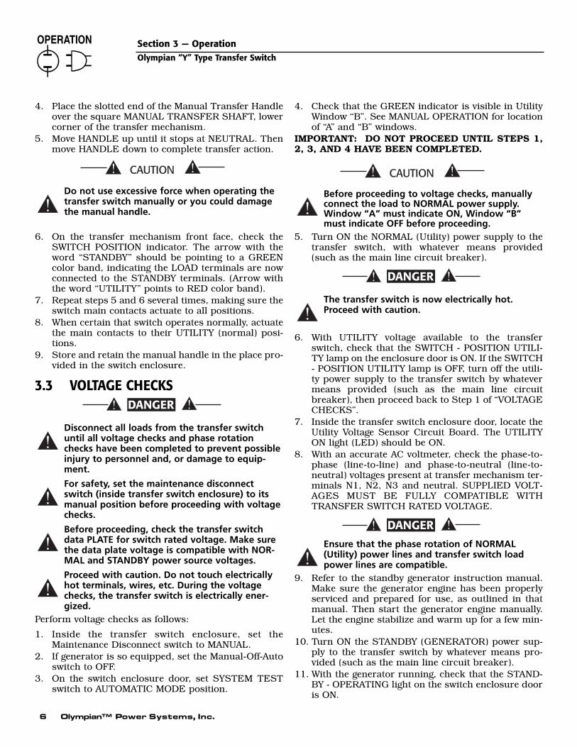
4. Place the slotted end of the Manual Transfer Handleover the square MANUAL TRANSFER SHAFT, lowercorner of the transfer mechanism.
5. Move HANDLE up until it stops at NEUTRAL. Thenmove HANDLE down to complete transfer action.
Do not use excessive force when operating thetransfer switch manually or you could damagethe manual handle.
6. On the transfer mechanism front face, check theSWITCH POSITION indicator. The arrow with theword “STANDBY” should be pointing to a GREENcolor band, indicating the LOAD terminals are nowconnected to the STANDBY terminals. (Arrow withthe word “UTILITY” points to RED color band).
7. Repeat steps 5 and 6 several times, making sure theswitch main contacts actuate to all positions.
8. When certain that switch operates normally, actuatethe main contacts to their UTILITY (normal) posi-tions.
9. Store and retain the manual handle in the place pro-vided in the switch enclosure.
3.3 VOLTAGE CHECKS
Disconnect all loads from the transfer switchuntil all voltage checks and phase rotationchecks have been completed to prevent possibleinjury to personnel and, or damage to equip-ment.
For safety, set the maintenance disconnectswitch (inside transfer switch enclosure) to itsmanual position before proceeding with voltagechecks.
Before proceeding, check the transfer switchdata PLATE for switch rated voltage. Make surethe data plate voltage is compatible with NOR-MAL and STANDBY power source voltages.
Proceed with caution. Do not touch electricallyhot terminals, wires, etc. During the voltagechecks, the transfer switch is electrically ener-gized.
Perform voltage checks as follows:
1. Inside the transfer switch enclosure, set theMaintenance Disconnect switch to MANUAL.
2. If generator is so equipped, set the Manual-Off-Autoswitch to OFF.
3. On the switch enclosure door, set SYSTEM TESTswitch to AUTOMATIC MODE position.
4. Check that the GREEN indicator is visible in UtilityWindow “B”. See MANUAL OPERATION for locationof “A” and “B” windows.
IMPORTANT: DO NOT PROCEED UNTIL STEPS 1,2, 3, AND 4 HAVE BEEN COMPLETED.
Before proceeding to voltage checks, manuallyconnect the load to NORMAL power supply.Window “A” must indicate ON, Window “B”must indicate OFF before proceeding.
5. Turn ON the NORMAL (Utility) power supply to thetransfer switch, with whatever means provided(such as the main line circuit breaker).
The transfer switch is now electrically hot.Proceed with caution.
6. With UTILITY voltage available to the transferswitch, check that the SWITCH - POSITION UTILI-TY lamp on the enclosure door is ON. If the SWITCH- POSITION UTILITY lamp is OFF, turn off the utili-ty power supply to the transfer switch by whatevermeans provided (such as the main line circuitbreaker), then proceed back to Step 1 of “VOLTAGECHECKS”.
7. Inside the transfer switch enclosure door, locate theUtility Voltage Sensor Circuit Board. The UTILITYON light (LED) should be ON.
8. With an accurate AC voltmeter, check the phase-to-phase (line-to-line) and phase-to-neutral (line-to-neutral) voltages present at transfer mechanism ter-minals N1, N2, N3 and neutral. SUPPLIED VOLT-AGES MUST BE FULLY COMPATIBLE WITHTRANSFER SWITCH RATED VOLTAGE.
Ensure that the phase rotation of NORMAL(Utility) power lines and transfer switch loadpower lines are compatible.
9. Refer to the standby generator instruction manual.Make sure the generator engine has been properlyserviced and prepared for use, as outlined in thatmanual. Then start the generator engine manually.Let the engine stabilize and warm up for a few min-utes.
10. Turn ON the STANDBY (GENERATOR) power sup-ply to the transfer switch by whatever means pro-vided (such as the main line circuit breaker).
11. With the generator running, check that the STAND-BY - OPERATING light on the switch enclosure dooris ON.
!
DANGER
!
DANGER
!
!
!
!
!
DANGER
!
Section 3 — OperationOlympian “Y” Type Transfer Switch

Olympian™ Power Systems, Inc. 7
12. With an accurate AC voltmeter, check phase-tophase (line-to-line) and phase-to neutral (line-toneutral) voltages present at transfer mechanism ter-minals E1, E2 and E3. Also check AC frequency atthose terminals. If frequency is incorrect, the enginegovernor may require adjustment. Generator ACoutput voltage and frequency must be compatiblewith transfer switch rated voltage and frequency.
Ensure that the phase rotation of STANDBY(GENERATOR) power lines and transfer switchNORMAL (UTILITY) and load power lines arecompatible.
13. If supplied voltage or frequency is incorrect, refer tostandby generator Owner’s Manual. If AC frequencyis incorrect, adjust engine governed speed. If voltageis incorrect, adjust generator’s voltage regulator orcorrect the problem.
14. When supplied voltage and frequency is correct,shut down the engine manually.
Supplied voltages from both NORMAL (Utility)and STANDBY (Generator) power sources mustbe compatible with transfer switch rated volt-age before proceeding.
15. Connect the transfer switch load to the transferswitch when “voltage checks” section has been com-pleted. Connect the load to the transfer switch bywhatever means provided [such as circuit break-er(s)], then proceed with the “ELECTRICAL OPER-ATION” section.
3.4 ELECTRICAL OPERATIONTest transfer system electrical operation as follows:
1. On the Utility Voltage Sensor circuit board, checkthat the UTILITY ON lamp (LED) is ON.
2. On the enclosure door, check that the SwitchPosition-Utility lamp is ON.
The UTILITY ON lamp (on circuit board) and theSWITCH POSITION-UTILITY lamp ( on enclosuredoor) must both be ON before proceeding toStep 3.
3. Refer to the appropriate owner’s manual. Be surethe standby generator is prepared for automaticoperation.
4. In the switch enclosure, set the MaintenanceDisconnect switch to AUTOMATIC.
5. Set the System Test switch to its NORMAL TESTMODE position. Generator startup and transfer tothe STANDBY power source should occur. Refer tothe SEQUENCE OF OPERATION, Section 3.13.
NOTE:
All systems are equipped with the Inphase MonitorControl board, and advisory lights on the circuitboard will light up to indicate operation of the vari-ous solid state timers that control automatic opera-tion. By observing these lights (LED’s), the operatorcan check the automatic operating sequences andtimes. See SENSOR AND TIMER ADJUSTMENTS,Section 3.16. For a detailed description of the auto-matic operating sequences, see SEQUENCE OFOPERATION, Section 3.13.
6. When the test is complete, return the System TestSwitch to its AUTOMATIC MODE position.Retransfer back to the UTILITY (normal) powersource. The generator should shut down accordingto circuit board timers.
3.5 TRANSFER MECHANISMThe transfer mechanism main contacts are actuated byan electro-magnetic coil. Power for that coil’s operationis taken from the side to which the LOAD is being trans-ferred. Thus, transfer to any power source cannot occurunless that power source is available to the switch.
Figure 3.2 — The Transfer Mechanism
!
!
DANGER
!
DANGER
Section 3 — OperationOlympian “Y” Type Transfer Switch

8 Olympian™ Power Systems, Inc.
3.6 MAIN CONTACTS OPERATIONOften called a “Y-type” transfer mechanism, this unit isa single solenoid, electrically actuated, mechanicallyheld type. Main contacts are 87% silver, 13% cadmiumoxide. The illustration shows the main contacts withLOAD connected to UTILITY source (Figure 3.3), LOADdisconnected from both power sources (neutral) (Figure3.4), and LOAD connected to the STANDBY powersource (Figure 3.5).
Figure 3.3 — Main Contacts at Utility
Figure 3.4 — Main Contacts at Neutral
Figure 3.5 — Main Contacts at Standby(Emergency)
3.7 SWITCHES AND ADVISORY LAMPSThis section will familiarize the reader with switchesand advisory lights on the transfer switch enclosuredoor, as well as with the Safety Disconnect Switchinside the switch enclosure.
Circuit board inside the switch door may also mountseveral switches. Operation of these switches will becovered in the section entitled SENSOR AND TIMERADJUSTMENTS.
3.8 SYSTEM TEST SWITCHThis switch permits operator selection of AUTOMATIC,NORMAL TEST or FAST TEST mode as follows (Figure3.6):
3.8.1 AUTOMATIC MODEUse this switch position for all normal automatic oper-ations. With AUTOMATIC MODE selected, any NORMALsource voltage that dropped below a pre-set value willresult in the automatic sequence of events listed in thechart in Section 3.14.
3.8.2 NORMAL TEST MODEPermits the operator to test automatic operations, just asthough an actual drop in NORMAL source voltage hadoccurred. See the chart in Section 3.14. During the test,observe the lights (LED’s) on the transfer switch circuitboard to monitor automatic operating sequences.
3.8.3 FAST TEST MODEPermits the operator to test system operation with allcircuit board timers accelerated to less than five sec-onds. Switch is spring-loaded back to AUTOMATICMODE, so continuously press the FAST TEST CON-TROL. Following the generator startup, loads are trans-ferred to the EMERGENCY (standby) power source assoon as EMERGENCY source voltage and frequencyhave reached the settings of STANDBY VOLTAGE andSTANDBY FREQUENCY sensors on the SYSTEM CON-TROL board.
Figure 3.6 — System Test Switch, StandbyOperating Light, and Switch Position Light
◆
◆
◆
Section 3 — OperationOlympian “Y” Type Transfer Switch

Olympian™ Power Systems, Inc. 9
3.9 STANDBY-OPERATING LIGHTThis light will go ON to tell the operator that the stand-by generator is running and that STANDBY (emergency)source power is available to the transfer switch.
3.10 SWITCH POSITION LIGHT3.10.1 EMERGENCY
The light will go ON when main current-carrying con-tacts have actuated to their STANDBY (emergency) posi-tion and that power source is available to the transferswitch.
3.10.2 UTILITYLight will go ON when main contacts have actuated toNORMAL (utility) position and that power supply isavailable to the transfer switch.
The switch is equipped with the Inphase MonitorControl circuit board. The sensors and timers areadjustable (see SENSOR AND TIMER ADJUST-MENTS).
3.11 SEQUENCE OF OPERATIONWhen acceptable NORMAL source voltage is available,you can observe the following:
• Utility voltage Sensor circuit board monitor’s NOR-MAL source voltage and UTILITY ON lamp is ON.
• Switch Position - UTILITY lamp is ON.• Transformer reduced LOAD (T) terminal voltage is
delivered to the 7-day exerciser board to operate the7-day exercise timer.
If you want, you can monitor automatic timers and sen-sors on the Inphase Monitor Control circuit board, byobserving light emitting diodes (LED’s) next to the sen-sor/timer adjustments.
3.11.1 SEQUENCE 1 - VOLTAGE DROPOUT• UTILITY source voltage drops below 75-95% of the
Voltage Pickup Setting (factory set to about 80%).The UTILITY ON lamp goes OFF.
• Voltage Dropout sensor is factory set to about 80% of“pickup” voltage.
• Voltage dropout below this sensor’s setting triggersSequence 2.
3.11.2 SEQUENCE 2 - LINE INTERRUPT DELAY• UTILITY voltage dropout below setting of Voltage
Dropout sensor turns on a lIne Interrupt DelayTimer.
• Line Interrupt Delay may be set for 0.1 to 10 seconds;has been factory set to about 5 seconds.
• If voltage dropout lasts longer than Line InterruptDelay setting, circuit board action closes the auto-matic start circuit (Wires 178 and 183). When thatcircuit closes, engine cranks and starts as controlledby a circuit board in the generator’s control panel.
• Once the standby generator starts, circuit board isturned ON (go to Sequence 3).
3.11.3 SEQUENCE 3 - ENGINE MINIMUM RUNAND WARMUP TIMERS
• This timer establishes the minimum length of timefor the generator to run before you can shut it down.Timer prevents shutdown of a cold engine.
• Timer is adjustable from 5 to 30 minutes; factory set-ting is about 20 minutes.
• An engine warmup timer is also turned ON. Thistimer permits engine to stabilize and warm up beforeloads are transferred to STANDBY. Timer isadjustable from 5 seconds to 3 minutes; factory set-ting is about 1 minute.
3.11.4 SEQUENCE 4 - STANDBY VOLTAGE ANDFREQUENCY SENSORS
• If generator AC output voltage and frequency is abovethe setting of these sensors, loads transfer to theSTANDBY power source.
• Adjust Standby Voltage Sensor between 75% and 95%or nominal supply frequency; factory setting is about90%.
• Adjust Standby Frequency Sensor between 80% and90% or nominal supply frequency; factory setting isabout 90%.
NOTE:
You can bypass the engine warmup timers by settingthe Engine Warmup Timer Bypass switch to ON.Loads are transferred to STANDBY as soon as gener-ator AC voltage and frequency have reached the set-tings of the Voltage and Frequency sensors withouthaving to wait for the engine to warm up.
3.11.5 SEQUENCE 5 - VOLTAGE PICKUP• If the UTILITY source voltage is restored above the
setting of the Voltage Pickup sensor, Sequence 5begins.
• Adjust Voltage Pickup between 85% to 95% of thenormal supply voltage from the UTILITY source; fac-tory setting is about 90%.
3.11.6 SEQUENCE 6 - RETURN TO UTILITYTIMER
• This timer prevents re-transfer that a Utility Sourcevoltage surge or transient might cause.
• Adjust timer between 1 to 30 minutes; factory settingis about 5 minutes.
◆
◆
◆
◆
◆
◆
◆
◆
Section 3 — OperationOlympian “Y” Type Transfer Switch

10 Olympian™ Power Systems, Inc.
• If UTILITY voltage remains above the setting of theVoltage Pickup Sensor for the time interval of theReturn to Utility Timer setting, loads are re-trans-ferred back to the UTILITY source.
3.11.7 SEQUENCE 7 - ENGINE COOL DOWNTIMER
• After the switch re-transfers loads back to UTILITY,this timer starts. When the interval has “timed out”,the automatic start circuit (Wires 178/183) is opened,and the engine shuts down.
• Timer permits engine to run at no-load for a fixedtime, so the engine internal temperature can stabilizebefore shutting down.
• Set the timer for 1-30 minutes; factory setting isabout 10 minutes.
NOTE:
Actual time between re-transfer back to UTILITY andengine shutdown is whichever is longer of the EngineCool Down timer setting or any time remaining onEngine Minimum run timer.
After the switch automatically re-transferred loads backto the UTILITY power source and generator has shutdown, the system is “armed” for Sequence 1 again.
3.13 TRANSFER SWITCH OPTIONSThe transfer switch may be equipped with one or moreof the following options:
• 3-wire Start System• Instrument Package• Deluxe Exerciser Circuit Board• NEMA 3R, 4, 4X, or 12 Enclosure
◆
Section 3 — OperationOlympian “Y” Type Transfer Switch
3.12 SEQUENCE OF OPERATION SETTINGSUnits with Inphase Monitor Control Circuit Board
ADJUST FACTORYSEQUENCE ACTION TIMER/SENSOR RANGE SETTING
—* UTILITY volts available - no action Voltage Dropout Sensor 75 - 95% 80%A* UTILITY voltage drops out Voltage Dropout Sensor 75 - 95% 80%B Line Interrupt Delay Timer Starts Line Interrupt Delay Timer 0.1 - 10 seconds 5 secondsC Line Interrupt Delay Timer Stops Line Interrupt Delay Timer .01 - 10 seconds 5 seconds— Engine cranks and startsD Engine Minimum Run Timer starts Engine Minimum Run Timer 5 to 30 minutes 20 minutes
E** Engine Warmup Timer Starts Engine Warmup Timer 5 sec. - 3 min. 1 minuteF STANDBY ON lamp ON
G** Engine Warmup Timer stops Engine Warmup Timer 5 sec. - 3 min. 1 minuteH Is STANDBY voltage good? Standby Voltage Sensor 75 - 95% 90%J Is STANDBY frequency good? Standby Frequency Sensor 80 - 90% 90%K Time Delay at NEUTRAL Time Delay Neutral Timer 0.1 - 10 seconds 5 secondsL Inphase Transfer Inphase Transfer Select None— Transfer to STANDBYM TRANSFER TO STANDBY lamp ON— STANDBY source powers LOADN UTILITY voltage restored Voltage Pickup Sensor 85 - 95% 90%O Return to UTILITY Timer ON Return to Utility Timer 1 - 30 minutes 5 minutesP Timed Delay at NEUTRAL Time Delay Neutral Timer 0.1 - 10 seconds 5 secondsR Inphase Transfer Inphase Transfer Select none 0.1 - 30 secondsS Signal Before Transfer LED lights Signal Before Transfer Timer 1 - 30 seconds 10 seconds— Re-transfer to UTILITY source
T*** Engine Cooldown Timer starts Engine Cooldown Timer 1 - 30 minutes 10 minutesU*** Engine Cooldown Timer stops Engine Cooldown Timer 1 - 30 minutes 10 minutes— Engine shuts down— UTILITY volts available - no action
* 75 - 95% of the Voltage Pickup Sensor setting** Engine Warmup Timer can be bypassed. See SENSOR AND TIMER ADJUSTMENTS
*** Following re-transfer to UTILITY source, engine shutdown will not occur until both Engine Minimum run and EngineCooldown timers have timed out.

Olympian™ Power Systems, Inc. 11
3.13.1 3-WIRE START SYSTEMThe standard generator start circuit on Generac trans-fer switches is a “2-wire” type. If the standby generatorbeing installed has a “3-wire” start/stop system, youmay need to use a transfer switch with a 3-wire system.
The optional 3-wire start system includes a 6-point ter-minal strip, a control relay, terminal strip decal andrequired wiring (Figure 3.7). These components areshown in the REPAIR PARTS section. Terminal stripconnections are shown below:
• Terminal 178 - + 12 volts DC supply. On Generacgenerators, connect to generator Terminal #15.
• Terminal 10 - Common ground. Connect to negative(-) side of the DC supply circuit (to Terminal #10 onGenerac generators).
• Terminal 213 - Acts as the COMMON terminal for thenormally-open (N.O.) START and the normally-closed(N.C.) STOP relay contacts.
• Terminal 136 - N.O. START terminal. On Generacgenerators, connect to generator Terminal #136.
• Terminal 18 - N.C. STOP terminal. On Generac gen-erators, connect to generator Terminal #18.
Figure 3.7 — 3-Wire Start System
3.13.2 INSTRUMENT PACKAGEThe optional instrument package includes (a) an ACvoltmeter, (b) an AC ammeter, (c) an AC frequencymeter, (d) an hourmeter, and (e) a phase selector switch.Several current transformers are required to operatethe instrument package, i.e., two for single phase sys-tems, three for 3-phase systems. Use the phase selectorswitch to select the 1-phase voltage and current beingread as follows:
For 3-phase systems use the switch as follows:
Figure 3.8 — Instrument Package
3.13.3 OPTIONAL DELUXE EXERCISERCIRCUIT BOARD
See OPTIONAL DELUXE EXERCISER CIRCUITBOARD SETTINGS, Section 3.21.
3.13.4 NEMA 12 ENCLOSURENational Electrical Manufacturer’s Association (NEMA)12 enclosure. This type of enclosure is intended for useindoors to provide a degree of protection against dust,falling dirt, and dripping, non-corrosive liquids. Askyour Dealer/Distributor or consult the factory fordetails.
3.13.5 NEMA 3R ENCLOSURENational Electrical manufacturer’s Association (NEMA)3R enclosure. This type of enclosure is intended for useoutdoors to protect enclosed parts from windblowndust and water. The enclosure is sealed for dust, rain orsleet and is ice resistant. Ask your Dealer/Distributor orconsult the factory for details.
◆
◆
◆
◆
◆
Section 3 — OperationOlympian “Y” Type Transfer Switch
SWITCH OPERATION CURRENT READING VOLTAGE READING1 Line 1 Line 1 to Neutral2 Line 2 Line 2 to Neutral3 No reading Line 1 to Line 2
OFF No reading No reading
SWITCH OPERATION CURRENT READING VOLTAGE READING1 Phase A Phase A to Phase B2 Phase B Phase B to Phase C3 Phase C Phase C to Phase A
OFF No reading No reading

3.13.6 NEMA 4 ENCLOSURENational Electrical Manufacturer’s Association (NEMA)4 enclosure. This type of enclosure is intended for useindoors or outdoors to provide a degree of protectionagainst windblown dust and rain, splashing water, andhose-directed water: undamaged by the formation of iceon the enclosure. Ask your Dealer/Distributor or con-sult the factory for details.
3.13.7 NEMA 4X ENCLOSURENational Electrical Manufacturer’s Association (NEMA)4X enclosure. This type of enclosure is intended for useindoors and outdoors to provide a degree of protectionagainst corrosion, windblown dust and rain, splashingwater, and hose-directed water: undamaged by theformation of ice on the enclosure. Ask yourDealer/Distributor or consult the factory for details.
3.13.8 ADDITIONAL OPTIONSFor information on additional options not covered inthis manual, ask you Dealer/Distributor or consult thefactory.
3.14 SENSOR AND TIMER ADJUSTMENTS— SENSING CIRCUIT BOARD
3.14.1 VOLTAGE DROPOUT SENSORThis sensor (Figure 3.9) establishes the NORMAL powersource voltage which generator startup and transfer toSTANDBY (Emergency) power source occurs. Adjust thesensor to any voltage between 75-95% of the nominalvoltage Pickup Sensor setting, by turning the adjustingknob to the desired setting (in percent). Sensor is facto-ry set to about 80% of the Voltage Pickup Sensor setting.
3.14.2 VOLTAGE PICKUP SENSOREstablishes the NORMAL power source voltage at whichre-transfer back to that power source occurs. Turnknob to adjust setting to 85-95% of the nominal NOR-MAL source supply voltage. Sensor has been factory setto about 90% of nominal rated NORMAL source voltage.
3.14.3 LINE INTERRUPT DELAY TIMEREstablished a definite time interval between NORMALsource voltage dropout below the setting of the VoltageDropout Sensor and generator startup. This time inter-val is necessary to prevent false generator starts thatvoltage transients might otherwise cause. Adjust timerfrom 0.1 to 10 seconds; is factory set to about five sec-onds.
Figure 3.9 — Sensing Circuit Board Panel
3.15 ADJUSTMENTS ON INPHASEMONITOR CONTROL CIRCUIT BOARD
The Inphase Monitor Control board is operational onlywhen the generator set is running. Transfer will occurwhen UTILITY and GENERATOR voltage and phase arecomparatively equal with a maximum difference of 20°between the power sources. To assure precision match-ing control, minimum voltage and frequency ranges arespecified by the operator. In addition, each inphase con-trol is programmed with the use of an onboard DIPswitch to match the actuation time of the correspondingswitch. Inphase transfer is used only between two livepower sources and NOT during a UTILITY source fail-ure. The Inphase Monitor Control board (Figure 3.10) isdesigned to transfer loads under the following condi-tions:
• When generator set frequency is between 58-62 Hz(48-52 Hz for 50 Hz systems).
• When generator set and utility power source frequen-cies are within 2 Hz.
• When the generator set and utility source voltage arewithin 85-100 percent of normal voltage.
• When both power sources are able to come into phasewithin 10 seconds.
• When less than 10 seconds has elapsed since theengine warmup timer has indicated “go ahead.”
If any one of the preceding conditions are not met with-in 30 seconds, the system will automatically revert toTime delay Neutral (if selected). If Time Delay Neutral isnot selected, the switch will transfer immediately afterfailing to do an inphase transfer within the 30 secondwindow.
3.15.1 ENGINE WARMUP TIMERPermits the engine to warm up before transferringLOAD from NORMAL to STANDBY power. Reset timerto any time interval between 5 seconds and 3 minutes;factory set to about 1 minute.
◆
◆
◆
◆
◆
◆
◆
12 Olympian™ Power Systems, Inc.
Section 3 — OperationOlympian “Y” Type Transfer Switch

Olympian™ Power Systems, Inc. 13
Section 3 — OperationOlympian “Y” Type Transfer Switch
3.15.2 ENGINE MINIMUM RUN TIMEREstablishes the minimum length of time the generatormust run before it can be shut down automatically.Timer prevents a cold engine from being shut down. Itis factory set to about 20 minutes, but you can reset theinterval between 5 and 30 minutes.
3.15.3 RETURN TO UTILITY TIMEREstablishes time interval between restoration of NOR-MAL source voltage above the setting of the VoltagePickup Sensor and re-transfer back to that source.This time interval is necessary, to prevent re-transferthat otherwise might occur as a result of transient volt-ages. Timer may be reset to any interval between 1 and30 minutes; factory set to about 5 minutes.
3.15.4 ENGINE COOL DOWN TIMERProvides a time delay between automatic re-transferback to the NORMAL source and engine shutdown.This permits internal engine-generator temperatures tostabilize at “no-load” prior to shutdown. Set timerbetween 1 and 30 minutes; factory set to about 10 min-utes.
NOTE:
The actual time interval between re-transfer back toNORMAL and generator shutdown, is the timeremaining on Engine Minimum Run timer or timesetting of the Engine Cool Down Timer, whichever islonger.
3.15.5 STANDBY VOLTAGE SENSORAfter engine starts automatically, the system does nottransfer LOAD to STANDBY power source until genera-tor AC output voltage has reached the setting of this sen-sor. Factory set to about 90% of the nominal rated volt-age, but you can reset between 75% and 95% of theunit’s rated voltage.
3.15.6 STANDBY FREQUENCY SENSORThis adjustment allows the installer or operator toselect the minimum required frequency of the standbypower source. It is adjustable between 80-90%. Factoryset to 90%.
3.15.7 SIGNAL BEFORE TRANSFER TIMERIf you select this function, this timer will control theamount of time signal remains active. Timer isadjustable from 1 to 30 seconds; factory set to about 10seconds.
NOTE:
The “Signal Before Transfer” feature provides a timedelay that allows elevators to continue operatingbefore transfer to another power supply occurs.
◆
◆
◆
◆
◆
◆
Figure 3.10 — Inphase Monitor Control Panel

3.15.8 TIME DELAY NEUTRALThis timer holds the transfer mechanisms main con-tacts in the “Neutral” position for the time you haveselected. “Neutral” is the main contacts position wherethe LOAD is disconnected from both UTILITY andSTANDBY power supplies. Timer is adjustable from 0.1and 10 seconds; factory set to about 5 seconds.
3.15.9 CALIBRATION MODE SWITCHThis switch has three positions, identified as “STDBY”,“OFF” and “UTIL”. The switch allows the installer oroperator to calibrate the circuit board to the existinggenerator set output voltage and to the existing UTILITYpower source voltage. The board must be calibrated toboth power source voltages in order to initiate transferand re-transfer at the correct voltages. To calibrate thecircuit board to the correct voltage, see “Calibrating theCircuit Board.”
3.15.10 INPHASE TRANSFER SELECT SWITCHThis switch allows the operator or installer to selecteither “Inphase Transfer” or “Time Delay Neutral” oper-ation. The switch may be positioned as follows:
• Switch at ON: Inphase transfer operation is selected.• Switch at OFF: Time Delay Neutral is activated if
selected.
3.15.11 SIGNAL BEFORE TRANSFER SWITCHThis switch allows the operator or installer to select the“Signal Before Transfer” feature or to turn OFF the fea-ture. To activate the feature, set the switch to ON. Toturn off the feature, set the switch to OFF.
3.15.12 ENGINE WARMUP TIMER BYPASSSWITCH
To bypass Engine Warmup Timer and transfer as soonas generator voltage and frequency have reached the set-ting of the Standby Voltage and Frequency Sensors, setswitch to ON. To place engine warmup Timer back intothe automatic operating system, set the switch to OFF.
3.15.13 TRANSFER ON EXERCISE SWITCHFor transferring LOAD to the STANDBY source duringthe 7-day exercise cycle, set switch to ON. For no trans-fer during the exercise, set switch to OFF.
3.15.14 ADVISORY LAMPSThe advisory lamps on the Inphase Control board con-sist of 9 LED’s (light emitting diodes) and include thefollowing:
• The four red timer lamps will turn ON when theirrespective timers are activated.
• The “Inphase Transfer Selected” lamp goes ON whenInphase Transfer Select switch is set to ON, indicat-ing the system will operate in its “Inphase” mode (andNOT in Time Delay Neutral mode).
• The Time Delay Neutral (TDN) Timer lamp will turnON when the TDN timer is running.
• The Signal Before Transfer Timer lamp will turn ONfor the duration of the Signal Before Transfer Timer,when it is turned ON.
• Transfer to Standby Lamp goes ON when LOAD hasbeen transferred to STANDBY power source.
• Standby run Signal will go ON when the generator isrunning and the Inphase Monitor Control circuitboard is operational and controlling the generator.
3.16 CALIBRATING THE INPHASEMONITOR CONTROL CIRCUIT BOARD
The Inphase Monitor circuit board must be calibratedto existing STANDBY and UTILITY source voltages if thesystem is to operate properly. To calibrate the circuitboard, two adjustment potentiometers (R102 andR107) are provided in the lower left corner of the circuitboard (Figure 3.11). The board must be calibrated asfollows:
1. Check that UTILITY supply voltage is available tothe system.
2. Start the generator, let it stabilize and warm up.3. Set the Calibration Mode Switch to “STDBY” and
observe the four top LED’s on the circuit board(Warmup Timer, Minimum Run Timer, Return toUtility Timer and Cool down Timer). These are theRED lamps.
• If the two upper LED’s are illuminated, calibrationis set too low.
• If the two bottom LED’s are illuminated, calibrationis set too high.
4. On the circuit board, adjust potentiometer R102until only the two center LED’s are illuminated(Minimum Run and Return to Utility timers).
5. Now, set the Calibration Mode switch to “UTIL” andobserve the four upper LED’s on the circuit board.
6. Adjust potentiometer R107 until only two centerLED’s are illuminated (Minimum Run and Return toUtility).
7. Set the Calibration Mode Switch to “OFF”. TheInphase Monitor Control board is calibrated.
NOTE:
With the Calibration Mode Switch set to “STDBY” or“UTIL”, the four top LED’s should turn ON insequence. That is, the lights should sweep on andoff, from one light to the next. Calibration isobtained when the two center lamps of the four(Minimum Run and Return to Utility) are illuminat-ed. This establishes 100% rated voltage.
◆
◆
◆
◆
◆
◆
◆
14 Olympian™ Power Systems, Inc.
Section 3 — OperationOlympian “Y” Type Transfer Switch

Olympian™ Power Systems, Inc. 15
Section 3 — OperationOlympian “Y” Type Transfer Switch
NOTE:
The Inphase Monitor Control circuit board should becalibrated when the transfer switch has beeninstalled as part of an operating system. Also,replacement circuit boards must be calibrated.
Figure 3.11 — Inphase Monitor Control CircuitBoard
3.17 CIRCUIT BOARD SWITCH SW1On the Inphase Monitor Control Board, a switch assem-bly consisting of a bank of eight miniature switches isidentified as “SW1” is usually set up at the factory andshould require no additional configuring (Figure 3.12).
NOTE:
On boards not installed at the factory, SW1 must beset by the installer. SW1 must be set to match thetype of transfer switch in which the board isinstalled.
The individual switches on SW1 are numbered from “1”(bottom) through “8” (top), as shown in figures 3.11 and3.12. To make the circuit board compatible to the spe-cific transfer switch assembly, set the switches as indi-cated in the chart below. Improper settings may causetransfer outside the 20-degree specification.
Figure 3.12 — Circuit Board Switch SW1
3.18 ADJUSTMENTS ON 7-DAY EXERCISERCIRCUIT BOARD
3.18.1 SET EXERCISE DAY AND TIME OF DAYOn the day and at the time of day you want the systemto start and exercise, press the GENERATOR EXER-CISE switch and hold it there for about 15 seconds.The generator will start and exercise 7 days later at theselected time of day.
◆
TRANSFER SWITCH SWITCH RATED 208 SWITCH RATED 240
1 2 3 4 5 6 7 8 1 2 3 4 5 6 7 8
105 amps, 2-pole (63302) * on off on on off on off * on off on on on on off
105 amps, 3-pole (62642) * on off on off on on on * on off on on off on on
105 amps, 4-pole (63597) * on off on off off on off * on off on off on on off
150 amps, 2 pole (63312) * on off on on off off on * on off on on on off off
150 amps, 3-pole (62643) * on off on off on off on * on off on on off on off
150 amps, 4-pole (63599) * on off on off off off off * on off on off on off off
200 amps, 2-pole (62677) * on off on off off on off * on off on off on on off
200 amps, 3-pole (64198) * on off off on on off on * on off on off off on on
200 amps, 4-pole (63598) * on off on off off on on * on off on on off off on
300 amps, 2-pole (62645) * on off on off on off off * on off on off on on on
300 amps, 3-pole (62646) * on off on off on on on * on off on on on off off
300 amps, 4-pole (64100) * on off on off on on on * on off on on on off off
420 amps, 2-pole (62647) * on off on off on off off * on off on off on on on
420 amps, 3-pole (62648) * on off off on on on off * on off on off off on on
420 amps, 4-pole (64344) * on off on off off on off * on off on on off off on
* Set Switch 1 to OFF for 60 Hz systems; set Switch to ON for 50 Hz systems
DIP Switch Settings - Y-Type Transfer Switches

Figure 3.13 — 7-Day Exerciser
3.19 OPTIONAL DELUXE EXERCISECIRCUIT BOARD SETTINGS
Always adjust the board in the exact order given (Figure3.14).
1. Set Actual Day of Week: Locate the switch abovewhich appears the words “ADVANCE DAY”. Pressthis Advance Day switch while watching the lightedDAY OF WEEK indicator. That indicator advancesone day each time you press the switch. You canstop when the actual current day of the week is dis-played.
2. Set Actual Time of Day: Hold FAST SET switchdown while watching the lighted chronograph at leftside of circuit board. When close to actual currenttime of day, release the FAST SET switch. Then, usethe SLOW SET switch to complete adjustment ofactual time of day.
Figure 3.14 — Deluxe 7-Day Exerciser
3. Select Dat (or Days) of Exercise: A bank of eightminiature rocker switches is provided at right sideof circuit board. Switches 1 through 7 correspondto days of the week (Sunday through Saturdayrespectively). Switch 8 is not used. To select a day ofthe week for system exercise, move the correct num-bered switch to its ON position. A lighted bandappears next to that day. In this manner, the systemcan be set to exercise one, two or more days eachweek.
4. Select Exercise Time of Day: Push down on switchbelow the words DISPLAY EXERCISE TIME. Whileholding that switch down, press FAST SET andSLOW SET switches until the time you want is dis-played. A red dot next to the letters “PM” indicatesp.m. times.
3.20 CALIBRATE UTILITY VOLTAGESENSING CIRCUIT BOARD
The utility sensing interface reduces utility source volt-age ar a fixed ratio. Thus, if utility voltage varies fromthe nominal, sensing voltage to the circuit board alsovaries. For that reason, you may need to calibrate thecircuit board to match the system.
The installed transfer switch must be rated at avoltage and phase that is compatible with theutility and standby power supplies. DO NOTattempt to calibrate any utility voltage sensorboard on any non-compatible unit trying tomake the unit compatible.
Once the circuit board has been properly calibrated, thevoltage that was present during calibration establishes100 percent utility voltage for “pickup” and “dropout”settings. Utility source voltage must be available to thetransfer switch during calibration.
NOTE:
You must also use this procedure to calibrate areplacement circuit board. Follow these instructions:
1. In the transfer switch enclosure, set the SafetyDisconnect Switch to “Manual”.
2. On the Utility Voltage Sensor circuit board, locatetest points “TP3” and “TP4” and install a jumperlead.
3. Locate the small potentiometer “R10”. Turn thepotentiometer fully counterclockwise.
4. Now, turn the “R10” potentiometer SLOWLY clock-wise until the “Utility On” light emitting diode (LED)just turns ON.
5. Remove the jumper wire from “TP3” and “TP4”.6. Reset the Maintenance Disconnect switch to AUTO-
MATIC.
!
16 Olympian™ Power Systems, Inc.
Section 3 — OperationOlympian “Y” Type Transfer Switch

Olympian™ Power Systems, Inc. 17
Section 4 — MaintenanceOlympian “Y” Type Transfer Switch
RESULTS:
• If the “Utility On” LED does NOT go on as describedabove, replace the utility voltage sensor board.Calibrate the new board and perform a “Normal Test”of the system.
• If the “Utility On” LED goes ON, discontinue the test.
Figure 3.15 — Utility Voltage Sensing CircuitBoard
4.1 OPERATE TRANSFER SWITCHOperate the transfer switch at least once each month.This can be done by performing a NORMAL TEST of thesystem. Because the System Test switch only simulatesfailure of the UTILITY power source, service will beinterrupted only during the actual transfer of the load.
4.2 CLEAN AND INSPECT TRANSFERSWITCH
Protect the transfer switch against construction grit,metal chips, excessive moisture and other harmful dirtat all times. At least once each year turn OFF all powersupplies to the switch, then brush and vacuum awaydust and dirt that has accumulated inside the enclo-sure. After cleaning, inspect the transfer switch careful-ly. Look for evidence of arcing, burning, hot spots, char-ring and other damage. If any of these are found, havethe switch assembly checked by an authorized servicetechnician.
4.3 7-DAY EXERCISEROn each transfer action, the LOAD will be disconnectedfrom both power sources for a brief interval. Duringsuch brief intervals, the exercise timer is powered bythe 9 volt battery. However, the timer will not advanceduring the transfer. For that reason, it may be necessaryto reset the exercise timer periodically.
4.4 LUBRICATIONOperating parts inside the transfer mechanism havebeen properly lubricated at the time of assembly. Undernormal conditions no additional lubrication should berequired. The service technician should lubricate allrecommended points whenever major transfer mecha-nism components are replaced.
Use only specified greases to lubricate contactorparts. DO NOT USE ANY SUBSTITUTES.
Use the following lubricants for the:
1. Main Contacts (Between movable contact and bus-bars).
• Dow Corning (Molykote) BR2 Plus; (Mfg. by DowCorning Co., USA)
• Liqui-Moly (Mfg. by DAI TO Co., Ltd., Japan)2. Operating Mechanism (Used on the actuator and
other parts of the contactors. Excluding the mov-able contacts).
• Mobilgrease 28 (Mfg. by Mobil Oil Co.)• Mobiltemp SHC 32 (Mfg. by Mobil Oil Co.)• Polo Moly Complex Grease #NLG12 (Mfg. by Polo
Lubricants, USA)• Rheolube 363 (Mfg. by Nye Lubricants Inc., USA)
4.5 MAIN CURRENT CARRYINGCONTACTS
At least once annually, have an Authorized ServiceTechnician check the main current carrying contacts inthe transfer mechanism. He will repair or replace majorcomponents that have been found defective.
4.6 NINE-VOLT BATTERYThe transfer switch is equipped with an adjustableInphase Monitor Control circuit board. The battery con-nects to a separate 7-day exerciser circuit board.Battery power for Exercise Timer operation is onlyneeded during the short time interval when the transfermechanism main contacts are at NEUTRAL position(LOAD disconnected from both power sources). It isrecommended that the 9 volt battery be replaced onceeach year.
!

18 Olympian™ Power Systems, Inc.
Section 5 — NotesOlympian “Y” Type Transfer Switch

Olympian™ Power Systems, Inc. 19
Section 5 — NotesOlympian “Y” Type Transfer Switch

20 Olympian™ Power Systems, Inc.
Section 6 — Mounting Dimensions
Olympian “Y” Type Transfer Switch
200-400 Amp NEMA 1 Units
100-150 Amp NEMA 1 Units
Section 6 — Mounting Dimensions
Olympian “Y” Type Transfer Switch
Olympian™ Power Systems, Inc. 21
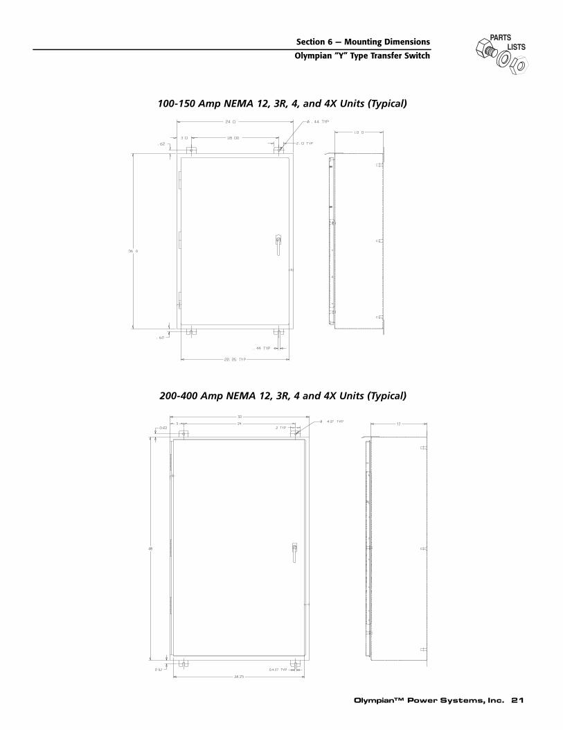
200-400 Amp NEMA 12, 3R, 4 and 4X Units (Typical)
100-150 Amp NEMA 12, 3R, 4, and 4X Units (Typical)

22 Olympian™ Power Systems, Inc.
Section 6 — Mounting Dimensions
Olympian “Y” Type Transfer Switch
200-400 Amp NEMA 12 Units With Instrument Package
100-150 Amp NEMA 12 Units With Instrument Package

Olympian™ Power Systems, Inc. 23
238
240V
RE
MO
TE
AU
TO
ST
AR
T
RE
TU
RN
TO
NO
RM
AL
BY
PA
SS
TA
RT
CO
NT
RO
L
EN
T P
AC
KA
GE
COM.
N.O. START
N.C. STOP
EF
OR
E T
RA
NS
FE
R
PT
ION
S
E2
1 4
213
7
136
18
7
RL
0
69
4
240
236
23710
8
CL
6107
9
147
148
E2
MA
N
AU
TE
1E1
E2
57
58
59
95
18 1
4
67
AM
220
419
FM
1614
T3
T2
T1
64
VM65
15
204
188
4
B2
T1 T2
189
187
7
N2
A2
B1
NC
CO
M
CO
M
NC
LS1
AU
X
NO
CO
M
E1
AU
X
CO
M
E2
T1
T2
125
185
7
A1
T3 T1
T2
126
1
AU
T N1
N2
MA
N
N1
N2
N2
20V
202
198
202
178
178
177
201
178
2 W
IRE
ST
AR
T17
7
178
202
CU
ST
OM
ER
CO
NN
EC
TIO
N2
WIR
E S
TA
RT10
178
0
183
183
CR
240V N
2
20V
20V
D
266
202
202
0
191
202AU
T
MA
N
177
A ATD
TR
NO
RM
AL
TE
ST
FA
ST
TE
ST
202
203
201
235
ON
193
194
23
194
178
177
A*
267
265
266
191
YL
264
202
L8L15
L3 L7L14
L10
L6L2 L16
L9L1L4
N.C
.L5L1
2
L13
224
225
227
2640
185
240V T
2T1
N1
E3
T3
N3
N2N1
T3
N3
T2
T1
185
178
177
2 W
IRE
ST
AR
T17
7
178
195
185 0
2 W
IRE
ST
AR
T17
8
177
224
N3
N2N1
N2
N1
N3
227
225
226
226
LO
E7
E9
E1
E5
E6
E2
E4
HI
199
202
S4
S3
LO HI
S2
P3
P4P1
TR
AN
SF
OR
ME
R, U
TIL
ITY
SE
NS
ING
RE
LAY
, SIG
NA
L B
EF
OR
E T
RA
NS
FE
R (
OP
T)
SW
ITC
H, R
ETU
RN
TO
NO
RM
AL
BY
PA
SS
(OP
T)
CLE
AR
LIG
HT
, SW
ITC
H P
OS
ITIO
N U
TIL
ITY
RE
LAY
, 3 W
IRE
ST
AR
T C
ON
TR
OL
SW
ITC
H, P
HA
SE
SE
LEC
TO
R (
OP
T)
RE
D L
IGH
T, S
WIT
CH
PO
SIT
ION
EM
ER
GE
NC
Y
TR
AN
SF
OR
ME
R, S
TA
ND
BY
SE
NS
ING
TR
AN
SF
OR
ME
R, L
OA
D P
OW
ER
SU
PP
LY
YE
LLO
W L
IGH
T, S
TA
ND
BY
OP
ER
AT
ING
TR
AN
SF
ER
SW
ITC
H C
ON
TA
CT
OR
TR
1
CIR
CU
IT B
OA
RD
CO
NN
EC
TO
RS
ME
TE
R, V
OLT
(O
PT
)
E, P
, SVM
YL
TR
3T
R2
TR
AN
SF
OR
ME
R, C
UR
RE
NT
RE
SIS
TO
R, T
DN
ME
TE
R, F
RE
QU
EN
CY
(O
PT
)M
ET
ER
, HO
UR
(O
PT
)
SW
ITC
H, S
YS
TE
M T
ES
T
RE
LAY
, TIM
E D
ELA
YR
ELA
Y, T
RA
NS
FE
R
SR
TD
TR
SW
4
SW
2S
W3
SW
1
PS
W
RLRFM
HMD
ME
TE
R, A
MP
(O
PT
)A
TS
CR
CL
AM
LEG
EN
D
7 -
8
11-
129
- 10
5 -
63
- 4
CO
NT
AC
TS
1-
2
20 -
19
16 -
15
X IN
DIC
AT
ES
CLO
SE
D
XX
XX X
POSI
TIO
N
X X1 2
3O
FF
PO
INT
TE
ST
INT
ER
FA
CE
INT
ER
NA
L C
ON
NE
CT
ION
S
CT
1
CT
3
CR
CR
SR
SW
1
PS
W
PS
W
TD R
AT
S
WH
ITE
TR
SW
1
A
LL R
ELA
Y C
ON
TA
CT
S S
HO
WN
WIT
H
W
IRE
N3 ,
59,A
ND
CT
3 U
SE
D O
N
A
TS
IN U
TIL
ITY
PO
SIT
ION
3
PH
AS
E S
YS
TE
M O
NLY
NO
TE
:
H4
X1
X3
X2
H1
SW
1
AB
H4
X1
X3
H3
H2
H1
TR
1
SW
2
SW
3
SW
4
INP
HA
SE
PC
BM
ON
ITO
R
H4
X1
X3
X2
H3
H1
TR
3
TR
2
UT
ILIT
Y
SE
E D
WG
. 700
6761
7 F
OR
PC
BT
IME
RE
XE
RC
ISE
7D
AY
PC
BS
EN
SIN
G
UT
ILIT
YV
OLT
AG
E
Section 7 — Electrical Schematics and Wiring DiagramsOlympian “Y” Type Transfer Switch
Electrical Schematic - 240V Transfer Switch - Drawing No. 91286

42 31A161211202
201
17719
4
202
54N
1
AB
1 46
4
59
178
178
178
178
10
236
136
18
237
240
5758
225
226
227
224
N3
N2N1
B9
AB9
AB
3 64
64
AT
SN
1
E1
T2
YE
LLO
W L
IGH
T, S
TA
ND
BY
OP
ER
AT
ING
TE
RM
. ST
RIP
, IN
ST
RU
ME
NT
PA
CK
AG
E (
OP
T)
()
TE
RM
. ST
RIP
, 2/3
WIR
E S
TA
RT
TE
RM
. ST
RIP
, RE
MO
TE
AU
TO
ST
AR
T (
OP
T)
()
ME
TE
R, V
OLT
(O
PT
)
RE
LAY
, TR
AN
SF
ER
TS
4T
S5
VM
YL
TS
2T
S3
TS
1T
R
PH
AS
E S
ELE
CT
OR
(O
PT
)(
)
ME
TE
R, H
OU
R (
OP
T)
()
CO
NN
EC
TO
R, U
TIL
ITY
VO
L. S
EN
SIN
G P
CB
TR
AN
SF
OR
ME
R, L
OA
D P
OW
ER
SU
PP
LY
CO
NN
EC
TO
R, I
NP
HA
SE
MO
NIT
OR
PC
BC
ON
NE
CT
OR
, UT
ILIT
Y V
OL.
SE
NS
ING
PC
B
RE
LAY
, SIG
NA
L B
EF
OR
E T
RA
NS
FE
R (
OP
T)
SW
ITC
H, S
YS
TE
M T
ES
T,
RE
LAY
, TIM
E D
ELA
Y
TR
AN
SF
OR
ME
R, S
TA
ND
BY
SE
NS
ING
,
SW
ITC
H, T
DN
ON
/OF
F,
SR
TR
2
TD
TR
1S
W4
SW
1
SW
3S
W2
RE
SIS
TO
R, T
DN
PS
W
RL SRL PFM
HM
TR
AN
SF
OR
ME
R, C
UR
RE
NT
RE
LAY
, 3 W
IRE
ST
AR
T C
ON
TR
OL
(OP
T)
()
LEG
EN
D
CO
NN
EC
TO
R, 7
DA
Y E
XE
RC
ISE
R P
CB
CLE
AR
LIG
HT
, SW
ITC
H P
OS
ITIO
N U
TIL
ITY
TR
AN
SF
ER
SW
ITC
H C
ON
TA
CT
OR
DIO
DE
(O
PT
)(
)
ME
TE
R, A
MP
(O
PT
)(
)
CT
1,2,
3D ECR
AT
SA
M CL
DA
SH
ED
LIN
ES
RE
PR
ES
EN
T W
IRIN
G F
OR
OP
TIO
NA
L F
EA
TU
RE
S.
NO
TE
:
224
225
226
227
177
202
199
224
177
178
178
178
178
198
T1
T2
202
265
T1
267
265
266
178
177
266178
178
202
202
0
202
177
201
17720
2
194
202
185
266
T2
177
266
T1
202
202
194
177
177
201
177
23
T1
67
204
T2
T2
1916
64
T3 T1
T2
67
204
T1
204
154
65
5
214
1
189
5758
59
6465
6465
204
T3
266
20120
2
264
0
193201
267
191
177
203
178
148
0
147
202
191
177
267
23
201
194
194
194
177
E1
E1
N1
N1
193
E1
264
177
191
177
202
125
0
235
125
194
187
202
5958
5720
4
147
148
N1
126
188
E1
188
225
224
227
226
136213
191
237
E2
178
178
178
178
E1
X3
183
178
178
178
178
236240
10
202
185T2
T2
T1 26
6
185
0
X3
T1
238
183
236
18
240
236
238
237
237
240
188
T2T1
225
226
227
189
224
N3
N2N1
148 E1
187
N2
1910
N1
E1 N
1
177
240236
183
236
125
108
194
108
267
183
10213
240
237238
188
189
T2
E2
E1
N1
185
N2
N2
N1
188E2
189
185
183
E2
N2
18
183
187107
N2
B1
B2
A2
A1
126
188
204
T3
59
5758
188
187
107
126
N1
147
148
107
147
E3
E2
E1
204
575859
T2
E2
T1
N3
N2
T2
TI
185
114
8
147
2 3
N2
N1
T3
N3
57204
58
N3
N3
59
N1T3
59
T35758
204
N1
N2
N1
TS3
SW
4
SPE
HM
VM
AMFM
PS
W
-+
L
CL
SW
2S
W3
TR
1
TS2
TR
2
TS2
TS4
CT
3
CT
2
CT
1
R
SE
NS
ING
INT
ER
FA
CE
UT
ILIT
Y
TR
3
SW
1
TS
5
TD
24 Olympian™ Power Systems, Inc.
Section 7 — Electrical Schematics and Wiring DiagramsOlympian “Y” Type Transfer Switch
Wiring Diagram - 240V Transfer Switch - Drawing No. 91397-A

Olympian™ Power Systems, Inc. 25
177
178
227
226
225
224
P1
P3
P4
S3
S4
S2
LO HI
185 0
0
185
L15
L14
199
202
L2
L7L6
L4L3
201
202
203
177
178
L12
191
L13
192
L11
23
L119
4
L10
193
YL
TR
A B
177
183
178
178
10C
R
178
178
OP
TIO
NA
L2-
WIR
E S
TA
RT
CU
ST
OM
ER
CO
NN
EC
TIO
N
N1
N2
N3
224
225
226
227
N1
N2
N3
E3
E2
E1
T1
T2
T3
CO
MC
OM
NO
NC
126
185
N1
N2
T2T1
T3
N2
N1
N2
N3
N2
N3
T3
T2
T1
185
147
148
E2
CL
RL
0
178
177
191
192
00
191
D
X2
X1
E2
E1
E2
240V
H1
H4
AM
204
67
204
57
58
59
21 5 9
4
T1
T2
T3
65 64
VM
FM
15
19
1614
71
74
213
136
18 N.C. STOP
N.O. START
COM.
X2 X1
H1
H4
240V
HI
LO
LO +12
V
1
712
5
N2
9
LOAB
235
224
225
226
227
178
177
74
187
188
189
T1
T2
B2 E2
E2
A1
A2
N2
T2
T1
6107
108
E1
23 194
193
B1
SW
ITC
H, T
DN
ON
/OF
FS
W3
AT
ST
RA
NS
FE
R S
WIT
CH
CO
NT
AC
TO
R
YL
VM
TR
2T
R1
TD
SW
2S
W1
YE
LLO
W L
IGH
T, S
TA
ND
BY
OP
ER
AT
ING
ME
TE
R, V
OLT
TR
AN
SF
OR
ME
R, L
OA
D P
OW
ER
SU
PP
LYT
RA
NS
FO
RM
ER
, ST
AN
DB
Y S
EN
SIN
G
RE
LAY
, TIM
E D
ELA
Y,
SW
ITC
H, M
AIN
TE
NA
NC
E D
ISC
ON
NE
CT
RE
D L
IGH
T, S
WIT
CH
PO
SIT
ION
EM
ER
GE
NC
Y
SW
ITC
H, P
HA
SE
SE
LEC
TO
R
ME
TE
R, F
RE
QU
EN
CY
TR
AN
SF
OR
ME
R, C
UR
RE
NT
CLE
AR
LIG
HT
, SW
ITC
H P
OS
ITIO
N U
TIL
ITY
ME
TE
R, A
MP
RL
PS
W
FM
CL
AM
LEG
EN
D
RR
ES
IST
OR
, TD
N
SE
NS
ING
PC
B
AB
UT
ILIT
Y (
ST
AN
DA
RD
)S
EN
SIN
G IN
TE
RF
AC
E
CP
UP
CB
AT
S
TD
SW
1
SW
1
TR
SW
1
SW
2
OP
TIO
NA
L
TR
1
PS
W
CT
3
CT
1
PS
W
OP
TIO
NA
L IN
ST
RU
ME
NT
PA
CK
AG
E
NO
TE
:
WIR
E N
3,59
,AN
D C
T3
US
ED
ON
3
PH
AS
E S
YS
TE
M O
NLY
SE
E D
WG
. 700
6761
7 F
OR
INT
ER
FA
CE
INT
ER
NA
L C
ON
NE
CT
ION
S
OP
TIO
N -
3 W
IRE
ST
AR
T
TR
2
TR
VO
LTA
GE
UT
ILIT
Y
A
LL R
ELA
Y C
ON
TA
CT
S S
HO
WN
WIT
H
AT
S IN
UT
ILIT
Y P
OS
ITIO
N
SW
3
R
Section 7 — Electrical Schematics and Wiring DiagramsOlympian “Y” Type Transfer Switch
Electrical Schematic - 240V Transfer Switch - Drawing No. 75017

1 2 3 44321
N1
E1
177
177
194
183
183
178
178
227
N3
226
225
224
N2N1
178
202
199
224
225
226
227
227
226
225
224
178
177
178
178
178
192
191
183
H1
X2
X1
H4
227
226
225
224
148
147
N2 N1
E2 E1
185
T2T1
N1
N2
T1
T2
185
E2
N1
X2
X1
H4
H1
107
108
B96
1 7 A
125
23
194
177
N1
N1
N1
E1
E1
23 185 0 E1 0
148
147
0
192
191
177
0
191
192
193
202
203
178 178
202
199
194
201
NO
TE
:
WIR
E N
O. N
3 &
226
U
SE
D O
N 3
Ø
SY
ST
EM
S O
NLY
N3
A13 9 B
126
194
194
194
235
126
177
N1
N2
7
N1
194
194
194
N3
N3
185
187
189
188
6
191191
192
0
0
147
148
192
177
107
191
15
193
178
23
185 0
202
AT
S
2-W
IRE
ST
AR
TC
US
TO
ME
R C
ON
NE
CT
ION
321
E1TI
N1
T2
T1
B2
B1
A2
A1
E2
T2
N2
E3
T3
N3
TD
TS
TR
TR
2
YL
SW
3
RE
LAY
, TIM
E D
ELA
Y
LEG
EN
D
CP
U
AT
S P SRL
CO
NN
EC
TO
R, C
EN
TR
AL
PR
OC
ES
SIN
G U
NIT
TR
AN
SF
ER
SW
ITC
H C
ON
TA
CT
OR
CO
NN
EC
TO
R, U
TIL
ITY
VO
L. S
EN
SIN
G P
CB
CO
NN
EC
TO
R, U
TIL
ITY
VO
L. S
EN
SIN
G P
CB
RE
D L
IGH
T, S
WIT
CH
PO
SIT
ION
EM
ER
GE
NC
Y
SW
ITC
H, S
YS
TE
M T
ES
T
TE
RM
INA
L S
TR
IPR
ELA
Y, T
RA
NS
FE
R
TR
AN
SF
OR
ME
R, S
TA
ND
BY
SE
NS
ING
TR
AN
SF
OR
ME
R, L
OA
D P
OW
ER
SU
PP
LY
YE
LLO
W L
IGH
T, S
TA
ND
BY
OP
ER
AT
ING
SW
2S
WIT
CH
, TD
N O
N/O
FF
TS
2
TR
1
TR
2
TR
SW
2
P S
TS
1
TD
UT
ILIT
YS
EN
SIN
GIN
TE
RF
AC
E
YL
RL
CL
CP
U
193
SW
3
235
R
26 Olympian™ Power Systems, Inc.
Section 7 — Electrical Schematics and Wiring DiagramsOlympian “Y” Type Transfer Switch
Wiring Diagram - 105-420A Transfer Switch - Drawing No. 74699

Olympian™ Power Systems, Inc. 27
227
226
225
224
N3
N2
N1
225
224
226
227
225
224
226
227
N3
N2
N1
N3
N2
N1
2 3 4
7 86
37
48
1 2
5 6
43
87
21
65
N2
N1
227
224
226
227
225
224
N3
N3
N2
N1
26
4
N3
N3
3
224
227
8
226
7
225
N2
N1
14
N2
2143
N1
21
224
58
227
5 686
N2
N1
43214321
225
7 822
7
676
N2
N1
AF
OR
400/
416/
480/
600
VO
LTT
HR
EE
PH
AS
EO
PE
RA
TIO
N
BF
OR
208/
240
VO
LTT
HR
EE
PH
AS
EO
PE
RA
TIO
N
CF
OR
240
VO
LTS
ING
LE P
HA
SE
OP
ER
AT
ION
224
B B CC
EE
D
AA A
A
A A A
B C
D
EE
Section 7 — Electrical Schematics and Wiring DiagramsOlympian “Y” Type Transfer Switch
Electrical Schematic - Utility Interface - Drawing No. 700-67617-B

28 Olympian™ Power Systems, Inc.
Section 7 — Electrical Schematics and Wiring DiagramsOlympian “Y” Type Transfer Switch
Electrical Schematic - Drawing No. 63373L
egen
dB
= B
ridge
Rec
tifie
rC
= S
olen
oid
Coi
lLS
1, L
S2
= L
imit
Sw
itch
(Sw
itch
Ope
ratio
n)LS
3 =
Lim
it S
witc
h (N
eutr
al P
ositi
on)
VR
= V
aris
tor

ITEM PART NO. QTY. DESCRIPTION
1 20A67621 1 BRACKET, TRANSFORMER MOUNTING2 20A67615 1 BLOCK, TERMINAL3 20A67614 3 TRANSFORMER, DUAL4 33514 6 SCREW, PAN HEAD MACHINE - NO. 8-32 X 1/2”5 22264 6 LOCKWASHER, NO. 86 22471 6 NUT, HEX - NO. 8-327 33502 2 SCREW, PAN HEAD MACHINE - NO. 6-32 X 3.4”8 22155 2 LOCKWASHER, NO.69 22985 2 FLATWASHER, NO.6
10 22188 2 NUT, HEX - NO. 6-3212 55199-A 6 FT. WIRE, INSULATED - NO 18 AWG. (TEW)13 20A67931 1 DECAL, INTERFACE
Olympian™ Power Systems, Inc. 29
Section 8 — Exploded Views & Parts ListsOlympian “Y” Type Transfer Switch
Interface Assembly - Drawing No. 67617

30 Olympian™ Power Systems, Inc.
Section 8 — Exploded Views & Parts ListsOlympian “Y” Type Transfer Switch
105-420A Assembly - Drawing No. 75000-C
79
78
7983
82
81
69
80 33
15
CPU COVER54
SENSING PCB-COVER
DECAL
DECAL 12
6
77 DECAL75
73
73
74
* 200,300,420 AMP 3-POLE SWITCH
**43 46
*71
72
68 DECAL
58
50
67
55
DECAL
52
51
21
55
5455
64
352 403938
49
DECAL13
33
7
6
5
32
65
49
1
14
30
98
45
DECAL
10
44
114
3
4642
62
48
22
4147
19
15
63
15
6156
30
1859(2)49
2222
23
21
53
23 20
49
49
49
24
25
28
3434
27
575757
34
26
49
COVER
P.C. BOARD
WALL
DECAL
OUTSIDE
OUTSIDE
INSIDE LUGS 80-85 IN-LB
OUTSIDE LUGS 110-115 IN-LB
LUG TO SWITCH STUD TORQUE SPEC.
TYPICAL
P.C. BOARD INSTALLATION
2
36
37

Olympian™ Power Systems, Inc. 31
Section 8 — Exploded Views & Parts ListsOlympian “Y” Type Transfer Switch
105-420A Assembly - Drawing No. 75000-C
ITEM PART NO. QTY. DESCRIPTION
1 63302 1 TRANSFER SWITCH-105A, 2-POLE62642 1 TRANSFER SWITCH-105A, 3-POLE63597 1 TRANSFER SWITCH-105A, 4-POLE63312 1 TRANSFER SWITCH-150A, 2-POLE62643 1 TRANSFER SWITCH-150A, 3-POLE63599 1 TRANSFER SWITCH-150A, 4-POLE62677 1 TRANSFER SWITCH-200A, 2-POLE64198 1 TRANSFER SWITCH-200A, 3-POLE63598 1 TRANSFER SWITCH-200A, 4-POLE62645 1 TRANSFER SWITCH-300A, 2-POLE62646 1 TRANSFER SWITCH-300A, 3-POLE64100 1 TRANSFER SWITCH-300A, 4-POLE62647 1 TRANSFER SWITCH-420A, 2-POLE62648 1 TRANSFER SWITCH-420A, 3-POLE64344 1 TRANSFER SWITCH-420A, 4-POLE
2 63617 2 RELAY, TRANSFER3 63384 1 LUG, NEUTRAL-105 & 150 A SWITCH
63657 1 LUG, NEUTRAL-200 & 300 A SWITCH62633 1 LUG, NEUTRAL-420 A SWITCH
4 62684 1 LUG, GROUNDING-105 & 150A SWITCH57329 1 LUG, GROUNDING-200, 300 & 420A SWITCH
5 74509 1 BRACKET, SAFETY DISCONNECT SWITCH6 74511 1 DECAL, SAFETY DISCONNECT SWITCH7 55868 1 SWITCH, SAFETY DISCONNECT-4PDT8 99084 - LUG-105 & 150A SWITCH (3 PER HOLE)
62704 - LUG-200 & 300 SWITCH (2 PER HOLE)62705 - LUG 400A SWITCH (2 PER HOLE)
9 21591 1 LUG ADAPTOR PLATE (1 PER HOLE FOREACH 100A SWITCH USED ON CENTER LUG)
21591 3 LUG ADAPTOR PLATE (3 PER HOLE FOREACH 150A SWITCH)
10 64109-A 1 COVER-105 & 150A, 2-POLE SWITCH64109-B 1 COVER-105 & 150A, 3-POLE SWITCH64109-C 1 COVER-105 & 150A, 4-POLE SWITCH64109-G 1 COVER-200, 300 & 420A, 2-POLE SWITCH64109-H 1 COVER-200, 300 & 420A, 3-POLE SWITCH64109-I 1 COVER-200, 300 & 420A, 4-POLE SWITCH
11 67210-A 1 DECAL, GROUND12 74525 1 DECAL, MANUAL OPERATION13 74510-A 1 DECAL, 105A TRANSFER SWITCH
74510-B 1 DECAL, 150A TRANSFER SWITCH74510-C 1 DECAL, 200A TRANSFER SWITCH74510-D 1 DECAL, 300A TRANSFER SWITCH74510-E 1 DECAL, 420A TRANSFER SWITCH
14 46357 1 BLOCK, TERMINAL - 6 POSITION15 56893 12 #10-24 X 1/2” CRIMPTITE16 47616 2 TRANSFORMER17 46689 1 BLOCK, TERMINAL - 4 POSITION18 63580 1 DECAL, TERMINAL BLOCK19 63321 1 HANDLE, MANUAL TRANSFER20 63578 1 PLATE, DATA21 68212 1 COMPARTMENT, PRINTED CIRCUIT BOARD22 64101 10 3/8”-16 FLANGED LOCK NUT23 36261 10 POP RIVET24 73681 1 DECAL, GTS
56298 1 DECAL, GENERAC NEMA 3R ONLY90257 1 DECAL, OLYMPIAN NEMA 3R ONLY87227 1 DECAL, OLYMPIAN
25 63385 1 DECAL, AUTOMATIC SEQUENCE26 57328 1 LENS, LAMP - CLEAR27 57327 1 LENS, LAMP - RED28 57325 1 LENS, LAMP - YELLOW29 55142 1 SWITCH, MODE - DPDT30 A1661 4 POP RIVET32 63595-A 1 DECAL, TESTING SEQUENCE 105 & 150A
63595-B 1 DECAL, TESTING SEQUENCE 200 & 300A63595-C 1 DECAL, TESTING SEQUENCE 420A
33 A2111 4 #10-32 X 5/16” FASTENER34 57514 3 HOLDER, LAMP35 38150 4 #8 FLAT WASHER36 A2284 4 #8-32 X 1/2” FASTENER37 22264 4 #8 LOCK WASHER38 90388 3 M6-1.0 X 12 TAPTITE39 49811 3 M6 FLAT WASHER
ITEM PART NO. QTY. DESCRIPTION
40 22097 3 M6 LOCK WASHER41 58000-L 1 M6-1.0 TRIC-NUT42 A2312 2 #10-32 X 1” FASTENER43 A2311 2 1/4”-20 X 1” SCREW44 24526 1 5/16-18 X 3/4” TAPTITE45 22129 1 5/16” LOCK WASHER46 22678 1CC LOC-TITE (TYPE A)47 64133 1 STUD (INCLUDES WING NUT)48 63558 1 ENCLOSURE 100-150A SWITCH
(INSTRUMENT PACKAGE)73959 1 ENCLOSURE 100-150A SWITCH (NEMA 12)73961 1 ENCLOSURE 100-150A SWITCH (NEMA 1)73961-C 1 ENCLOSURE 100-150A SWITCH (NEMA 3R)63559 1 ENCLOSURE 200-420A SWITCH
(INSTRUMENT PACKAGE)73960 1 ENCLOSURE 200-420A SWITCH (NEMA 12)73962 1 ENCLOSURE 200-420A SWITCH (NEMA 1)73962-C 1 ENCLOSURE 200-420A SWITCH (NEMA 3R)
49 57593 13 TIE-DOWN, CABLE50 67629 1 BOARD, UTIL. VOLT. SENS. -MULTI VOLTAGE51 67626 1 BOARD, SYSTEM CONTROL (CPU)52 20A67616 1 COVER, UTILITY VOLT. SENSING BOARD53 63582 1 DOOR, PRINTED CIR. BRD COMPARTMENT54 64525 12 SUPPORT, PRINTED CIRCUIT BOARD55 64526 32 #6-32 X 3/8” SELF-TAPPING SCREW56 64152 1 SUBPLATE - 105 & 150A SWITCH
63655 1 SUBPLATE - 200, 300 & 420A SWITCH57 40587 3 LAMP, 28 VOLTS58 63998 1 BATTERY, 9 VOLTS59 46669 2 JUMPER, TERMINAL BLOCK60 72956 - HARNESS, WIRING-105 & 150A SW. (NOT
SHOWN)73957 - HARNESS, WIRING 200, 300 & 420A SW. (NOT
SHOWN)61 62209 1 DECAL, UL62 26902 1 #8-32 X 1/4” TAPTITE (105 & 150A SWITCH ONLY)63 30B61617 1 INTERFACE, UTILITY (208/240 V 3-PHASE)
86961 1 INTERFACE, UTILITY (240 V 1-PHASE)64 68337 4 STAND-OFF, HEX 1” LG. (STANDARD
SENSING ONLY)65 54199 1 DECAL, HIGH VOLTAGE66 64761 - TIE WRAP, 5 5/8” LG. (NOT SHOWN)67 63981 2 GUIDE, SIDE68 63357 1 DECAL, MAC DT GTS69 63971 1 RESISTOR-250 OHM, 100 WATT71 62702 - LUG, TERM. 200 & 300A SW. ONLY (1 PER
POLE REQ.)62703 - LUG, TERM. 420A SW. ONLY (1 PER POLE REQ.)
72 26902 - #8-32 X 1/4” TAPTITE73 63378 4 TIE-DOWN, CABLE74 71775 1 COVER, CPU75 72252 1 GROMMET76 28199 1 SWITCH, TIME DELAY NEUTRAL BYPASS
74514-A 1 SWITCH P/N 6330274514-B 1 SWITCH P/N 6264274514-C 1 SWITCH P/N 6359774514-D 1 SWITCH P/N 6331274514-E 1 SWITCH P/N 6264374514-F 1 SWITCH P/N 6359974514-G 1 SWITCH P/N 6267774514-J 1 SWITCH P/N 6419874514-K 1 SWITCH P/N 6359874514-L 1 SWITCH P/N 6264574514-M 1 SWITCH P/N 6264674514-N 1 SWITCH P/N 6410074514-P 1 SWITCH P/N 6264774514-R 1 SWITCH P/N 6264774514-S 1 SWITCH P/N 64344
78 67989 18 M8-1.25 LOCK FLANGE NUT79 22131 10 3/8” FLAT WASHER80 63324 2 MOUNTING BRACKET, RESISTOR81 64510 1 DECAL, TERMINAL NOTE82 64110 1 DECAL, TERMINAL STRIP LOW VOLTAGE83 77228 1 DECAL, ENCLOSURE NOTE

P.C. BOARD
P.C. BOARD INSTALLATION
COVER
TYPICAL
21
55
** SEE NOTE
87
55
8990 88SENSING PCB-COVER64
54
55 54
** USED ONLY WITH #63919 BOARD
* 200,300,420 AMP 3-POLE SWITCH
INSIDE LUGS 80-85 IN-LB
OUTSIDE LUGS 110-115 IN-LB
LUG TO SWITCH STUD TORQUE SPEC.
7
9122
23
83
53
5052
67
79
21
5174
78
(NOT SHOWN)SIDE WALL SUPT. CHN'L ALSO
TRIM TO BE APPLIED TO93 17 59 18 56 2361 20
73
15
58
81
80
75
16
14
76
30
49
4341
33
63
70
84
15
69
177
114
65
4544
OUTSIDE DOOR
73
26 5734
24
573427 57 28 34
29
6
SIDE WALL
33
32
5
25 2 35
13
10
82*71
98 72
36 73 86 83 22
19
47
48
3
62
*
4642
*
12
96
95
97
99 98 30
31
363594 100100
68
403938
Section 8 — Exploded Views & Parts ListsOlympian “Y” Type Transfer Switch
105-420A Inphase Assembly - Drawing No. 91392-C
32 Olympian™ Power Systems, Inc.
ITEM PART NO. QTY. DESCRIPTION
1 63302 1 TRANSFER SWITCH-105A, 2-POLE62642 1 TRANSFER SWITCH-105A, 3-POLE63597 1 TRANSFER SWITCH-105A, 4-POLE63312 1 TRANSFER SWITCH-150A, 2-POLE62643 1 TRANSFER SWITCH-150A, 3-POLE63599 1 TRANSFER SWITCH-150A, 4-POLE62677 1 TRANSFER SWITCH-200A, 2-POLE64198 1 TRANSFER SWITCH-200A, 3-POLE63598 1 TRANSFER SWITCH-200A, 4-POLE62645 1 TRANSFER SWITCH-300A, 2-POLE62646 1 TRANSFER SWITCH-300A, 3-POLE64100 1 TRANSFER SWITCH-300A, 4-POLE62647 1 TRANSFER SWITCH-420A, 2-POLE62648 1 TRANSFER SWITCH-420A, 3-POLE64344 1 TRANSFER SWITCH-420A, 4-POLE
2 63617 2 RELAY, TRANSFER
ITEM PART NO. QTY. DESCRIPTION
3 63384 1 LUG, NEUTRAL - 105 & 150A SWITCH63657 1 LUG, NEUTRAL - 200 & 300A SWITCH62633 1 LUG, NEUTRAL - 420A SWITCH
4 62684 1 LUG, GROUNDING-105 & 150A SWITCH57329 1 LUG, GROUNDING-200, 300 & 420A SWITCH
5 74509 1 BRACKET, SAFETY DISCONNECT SWITCH6 74511 1 DECAL, SAFETY DISCONNECT SWITCH7 55868 1 SWITCH, SAFETY DISCONNECT-4PDT8 99084 - LUG-105 & 150A SWITCH (3 PER HOLE)
62704 - LUG-200 & 300A SWITCH (2 PER HOLE)62705 - LUG 400A SWITCH (2 PER HOLE)
9 21591 1 LUG ADAPTOR PLATE (1 PER HOLE FOREACH 100A SWITCH USED ON CENTERLUG)
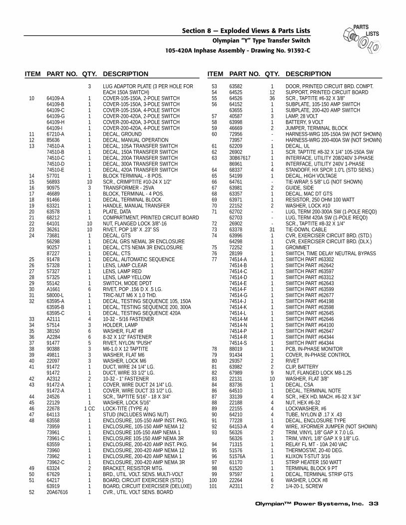
Olympian™ Power Systems, Inc. 33
Section 8 — Exploded Views & Parts ListsOlympian “Y” Type Transfer Switch
105-420A Inphase Assembly - Drawing No. 91392-C
ITEM PART NO. QTY. DESCRIPTION
3 LUG ADAPTOR PLATE (3 PER HOLE FOREACH 150A SWITCH)
10 64109-A 1 COVER-105-150A, 2-POLE SWITCH64109-B 1 COVER-105-150A, 3-POLE SWITCH64109-C 1 COVER-105-150A, 4-POLE SWITCH64109-G 1 COVER-200-420A, 2-POLE SWITCH64109-H 1 COVER-200-420A, 3-POLE SWITCH64109-I 1 COVER-200-420A, 4-POLE SWITCH
11 67210-A 1 DECAL, GROUND12 85636 1 DECAL, MANUAL OPERATION13 74510-A 1 DECAL, 105A TRANSFER SWITCH
74510-B 1 DECAL, 150A TRANSFER SWITCH74510-C 1 DECAL, 200A TRANSFER SWITCH74510-D 1 DECAL, 300A TRANSFER SWITCH74510-E 1 DECAL, 420A TRANSFER SWITCH
14 57701 1 BLOCK TERMINAL - 8 POS.15 56893 10 SCR., CRIMPTITE #10-24 X 1/2”16 90975 3 TRANSFORMER - 25VA17 46689 1 BLOCK, TERMINAL - 4 POS.18 91466 1 DECAL, TERMINAL BLOCK19 63321 1 HANDLE, MANUAL TRANSFER20 63578 1 PLATE, DATA21 68212 1 COMPARTMENT, PRINTED CIRCUIT BOARD22 64101 10 NUT, FLANGED LOCK 3/8”-1623 36261 10 RIVET, POP 1/8” X .23” SS24 73681 1 DECAL, GTS
56298 1 DECAL GRS NEMAL 3R ENCLOSURE90257 1 DECAL, CTS NEMA 3R ENCLOSURE87227 1 DECAL, CTS
25 91478 1 DECAL, AUTOMATIC SEQUENCE26 57328 1 LENS, LAMP CLEAR27 57327 1 LENS, LAMP RED28 57325 1 LENS, LAMP YELLOW29 55142 1 SWITCH, MODE DPDT30 A1661 6 RIVET, POP .156 D X .5 LG.31 58000-L 1 TRIC-NUT M6 X 1.0 THD.32 63595-A 1 DECAL, TESTING SEQUENCE 105, 150A
63595-B 1 DECAL, TESTING SEQUENCE 200, 300A63595-C 1 DECAL, TESTING SEQUENCE 420A
33 A2111 4 10-32 - 5/16 FASTENER34 57514 3 HOLDER, LAMP35 38150 6 WASHER, FLAT #836 A2284 6 8-32 X 1/2” FASTENER37 91477 5 RIVET, NYLON “PUSH”38 90388 3 M6-1.0 X 12 TAPTITE39 49811 3 WASHER, FLAT M640 22097 3 WASHER, LOCK M641 91472 1 DUCT, WIRE 24 1/4” LG.
91472 1 DUCT, WIRE 33 1/2” LG.42 A2312 2 10-32 - 1” FASTENER43 91472-A 1 COVER, WIRE DUCT 24 1/4” LG.
91472-A 1 COVER, WIRE DUCT 33 1/2” LG.44 24526 1 SCR., TAPTITE 5/16” - 18 X 3/4”45 22129 1 WASHER, LOCK 5/16”46 22678 1 CC LOCK-TITE (TYPE A)47 64113 1 STUD (INCLUDES WING NUT)48 63558 1 ENCLOSURE, 105-150 AMP INST. PKG.
73959 1 ENCLOSURE, 105-150 AMP NEMA 1273961 1 ENCLOSURE 105-150 AMP NEMA 173961-C 1 ENCLOSURE 105-150 AMP NEMA 3R63559 1 ENCLOSURE, 200-420 AMP INST. PKG.73960 1 ENCLOSURE, 200-420 AMP NEMA 1273962 1 ENCLOSURE, 200-420 AMP NEMA 173962-C 1 ENCLOSURE, 200-420 AMP NEMA 3R
49 63324 2 BRACKET, RESISTOR MTG.50 67629 1 BRD., UTIL. VOLT. SENS. MULTI-VOLT51 64217 1 BOARD, CIRCUIT EXERCISER (STD.)
63919 1 BOARD, CIRCUIT EXERCISER (DELUXE)52 20A67616 1 CVR., UTIL. VOLT SENS. BOARD
ITEM PART NO. QTY. DESCRIPTION
53 63582 1 DOOR, PRINTED CIRCUIT BRD. COMPT.54 64525 12 SUPPORT, PRINTED CIRCUIT BOARD55 64526 36 SCR., TAPTITE #6-32 X 3/8”56 64152 1 SUBPLATE, 105-150 AMP SWITCH
63655 1 SUBPLATE, 200-420 AMP SWITCH57 40587 3 LAMP, 28 VOLT58 63998 1 BATTERY, 9 VOLT59 46669 2 JUMPER, TERMINAL BLOCK60 72956 - HARNESS-WRG 105-150A SW (NOT SHOWN)
73957 - HARNESS-WRG 200-400A SW (NOT SHOWN)61 62209 1 DECAL, UL62 26902 1 SCR. TAPTITE #8-32 X 1/4” 105-150A SW63 30B67617 1 INTERFACE, UTILITY 208/240V 3-PHASE
86961 1 INTERFACE, UTILITY 240V 1-PHASE64 68337 4 STANDOFF, HX SPCR 1.0”L (STD SENS.)65 54199 1 DECAL, HIGH VOLTAGE66 64761 - TIE-WRAP, 5 5/8” LG (NOT SHOWN)67 63981 2 GUIDE, SIDE68 63357 1 DECAL, MAC DT GTS69 63971 1 RESISTOR, 250 OHM 100 WATT70 22152 2 WASHER, LOCK #1071 62702 - LUG, TERM 200-300A SW (1-POLE REQD)
62703 - LUG, TERM 420A SW (1-POLE REQD)72 26902 - SCR., TAPTITE #8-32 X 1/4”73 63378 31 TIE-DOWN, CABLE74 63996 1 CVR, EXERCISER CIRCUIT BRD. (STD.)
64298 1 CVR, EXERCISER CIRCUIT BRD. (DLX.)75 72252 1 GROMMET76 28199 1 SWITCH, TIME DELAY NEUTRAL BYPASS77 74514-A 1 SWITCH PART #63302
74514-B 1 SWITCH PART #6264274514-C 1 SWITCH PART #6359774514-D 1 SWITCH PART #6331274514-E 1 SWITCH PART #6264374514-F 1 SWITCH PART #6359974514-G 1 SWITCH PART #6267774514-J 1 SWITCH PART #6419874514-K 1 SWITCH PART #6359874514-L 1 SWITCH PART #6264574514-M 1 SWITCH PART #6264674514-N 1 SWITCH PART #6410074514-P 1 SWITCH PART #6264774514-R 1 SWITCH PART #6434474514-S 1 SWITCH PART #64344
78 88019 1 PCB, IN-PHASE MONITOR79 91434 1 COVER, IN-PHASE CONTROL80 29357 2 RIVET81 63982 2 CLIP, BATTERY82 67989 9 NUT, FLANGED LOCK M8-1.2583 22131 10 WASHER, FLAT 3/8”84 83736 1 DECAL, CSA86 64510 1 DECAL, TERMINAL NOTE87 33139 4 SCR., HEX HD. MACH. #6-32 X 3/4”88 22188 4 NUT, HEX #6-3289 22155 4 LOCKWASHER, #690 64210 4 TUBE, NYLON Ø .17 X .4391 77228 1 DECAL, ENCLOSURE TYPE92 64153-A 4 WIRE, XFORMER JUMPER (NOT SHOWN)93 56326 2 TRIM, VINYL 1/8” GAP X 7.0 LG.
56326 1 TRIM, VINYL 1/8” GAP X 9 1/8” LG.94 71315 1 RELAY FL MT - 10A 240 VAC95 51576 1 THERMOSTAT, 20-40 DEG.96 51576A 1 KLIXON T-STUT 3/1697 61170 1 STRIP HEATER 150 WATT98 61520 1 TERMINAL BLOCK 9 PT99 97597 1 DECAL, TERMINAL STRIP GTS
100 22264 6 WASHER, LOCK #8101 A2311 2 1/4-20-1, SCREW

Part No. 091415 Revision B (07/25/02) Printed in U.S.A.
Section 9 — WarrantyOlympian “Y” Type Transfer Switch
STANDARD ONE YEAR LIMITED WARRANTY FOROLYMPIAN™ TRANSFER SWITCHES
For a period of 1 (one) year from the date of original sale, an Olympian™ dealer will, at its option, repair orreplace any part(s) which, upon examination, inspection, and testing by an Olympian™ dealer, is found to bedefective under normal use and service. Any equipment that the purchaser/owner claims to be defective mustbe examined by the nearest Olympian™ dealer’s authorized warranty service facility. All transportation costsunder the warranty, including return to the factory, are to be borne and prepaid by the purchaser/owner.
WARRANTY SCHEDULE
• YEAR ONE — 100% (one hundred percent) coverage of on-site labor and parts listed.• TRANSFER SYSTEM — All Components.
All warranty expense allowances are subject to the conditions defined in the published GENERAC POLICIESAND PROCEDURES MANUAL.
* Rental units and demonstrators are warranted for 90 days. Rental units and demonstrators which areresold are not covered under the Olympian™ Generators warranty.
THIS WARRANTY SHALL NOT APPLY TO THE FOLLOWING:
1. Costs of normal maintenance i.e. tune-ups, associated part(s), adjustments, loose/leaking clamps, installationand start-up.
2. Failures due, but not limited to, normal wear and tear, accident, misuse, abuse, negligence, or improperinstallation or sizing.
This warranty is effective for all products manufactured after October 18, 1984, and supersedes all priorwarranties of Olympian™ Generators.
THIS WARRANTY IS IN PLACE OF ALL OTHER WARRANTIES, EXPRESSED OR IMPLIED, SPECIFICALLY,OLYMPIAN™ GENERATORS MAKES NO OTHER WARRANTIES AS TO THE MERCHANTABILITY OR FIT-NESS FOR A PARTICULAR PURPOSE.
OLYMPIAN™ GENERATORS ONLY LIABILITY SHALL BE THE REPAIR OR REPLACEMENT OF PART(S) ASSTATED ABOVE. IN NO EVENT SHALL OLYMPIAN™ GENERATORS BE LIABLE FOR ANY INCIDENTAL, ORCONSEQUENTIAL DAMAGES, EVEN IF SUCH DAMAGES ARE A DIRECT RESULT OF OLYMPIAN™ GENER-ATORS NEGLIGENCE.
Purchaser/owner agrees to make no claims against Olympian™ Generators based on negligence.
GENERAC® POWER SYSTEMS, INC. • P.O. BOX 8 • WAUKESHA, WI 53187PH: (262) 544-4811 • FAX: (262) 544-4851