owner's manual snow thrower - appliance partss manual 5 horse power 22" two-stage snow...
TRANSCRIPT

Owner's Manual
5 Horse Power
22" Two-Stage
Snow Thrower
Model No.247.887001
CAUTION: Before
using this product,read this manual and
follow all safety rulesand operatinginstructions.
SafetyAssemblyOperationServiceMaintenance
Espa5ol, p.29
Sears, Roebuck And Co., Hoffman Estates, IL 60179, U.S.A.Visit our website: www.sears.com/craftsman FORM NO. 769-00750C
Printed in U.S.A. (7/30/2004)

Content PageWarranty Information .................................... 2
Safe Operation Practices .............................. 3
Assembly ...................................................... 5
Operation ...................................................... 7
Maintenance ................................................. 11
Content PageService & Adjustment ....................................... 13
Off-Season Storage ......................................... 15
Trouble-Shooting ............................................. 16
Parts List ......................................................... 18
Espan51 ......................................................... 29
Two -Year Warranty on Craftsman Snow ThrowerFor two years from the date of purchase, when this Craftsman Snow Thrower is maintained, lubricated and tuned up according to the instruc-tions in the owner's manual, Sears will repair, free of charge, any defect in material and workmanship.If this Craftsman snow thrower is used for commercial or rental purposes, this warranty applies for only 30 days from the date of purchase.This warranty does not cover:
Expendable items which become worn during normal use, such as skid shoes, shave plate and spark plugs.Repairs necessary because of operator abuse or negligence, including bent crankshafts and the failure to maintain the equipmentaccording to the instructions contained in the owner's manual.
WARRANTY SERVICE IS AVAILABLE BY RETURNING THE CRAFTSMAN SNOW THROWER TO THE NEAREST SEARS PARTS & REPAIRCENTER IN THE UNITED STATES.This warranty applies only while this product is in use in the United States.This warranty gives you specific legal rights and you may also have other rights which may vary from state to state.
SEARS, ROEBUCK AND CO., D/817WA, HOFFMAN ESTATES, IL 60179
Repair Protection AgreementsCongratulations on making a smart purchase.Your new Craftsman®product is designed and manufactured for years of dependableoperation. But like all products, it may require repair from time totime. That's when having a Repair Protection Agreement can saveyou money and aggravation.
Here's what's included in the Agreement:Expert service by our 12,000 professional repair
_t specialists
Unlimited service and no charge for parts and labor onall covered repairs
Product replacement if your covered product can't be@P fixed
Discount of 10% from regular price of service and service-related parts not covered by the agreement; also, 10% off
regular price of preventive maintenance check
Fast help by phone - phone support from a Searstechnician on products requiring in-home repair, plus
convenient repair scheduling
Purchase a Repair Protection Agreement now and protect yourselffrom unexpected hassle and expense.
Once you purchase the Agreement, a simple phone call is all that ittakes for you to schedule service. You can call anytime day or night,or schedule a service appointment online. Sears has over 12,000professional repair specialists, who have access to over 4.5 millionquality parts and accessories. That's the kind of professionalism youcan count on to help prolong the life of your new purchase for yearsto come. Purchase your Repair Protection Agreement today!
Some limitations and exclusions apply. For prices and additionalinformation call 1-800-827-6655.
Sears Installation Service
For Sears professional installation of home appliances, garage dooropeners, water heaters, and other major home items, in the U.S.A.call 1-800-4-MY-HOME®.
Horsepower: 5
Engine Oil: SAE 5W30 Capacity: 21 oz.
Fuel: Unleaded Regular Capacity:
Spark Plug: RJ19LM
Eng ne: Craftsman Eng ne Mode 143.045003
Model Number ...........................................................
Serial Number ...........................................................
Date of Purchase ......................................................
Record both serial number and date of purchase and keep in asafe place for future reference.

_, ARNING: This symbol points out important safety instructions which, if not followed, could endangerthe personal safety and/or property of yourself and others. Read and follow all instructions in this manualbefore attempting to operate this machine. Failure to comply with these instructions may result in personalinjury. When you see this symbol--heed its warning.
_L ARNING: Engine Exhaust, some of its constituents, and certain vehicle components contain or emitchemicals known to State of California to cause cancer and birth defects or other reproductive harm.
DANGER: This machine was built to be operated according to the rules for safe operation in this manual. As withany type of power equipment, carelessness or error on the part of the operator can result in serious injury. Thismachine is capable of amputating hands and feet and throwing objects. Failure to observe the following safetyinstructions could result in serious injury or death.
Training1. Read, understand, and follow ail instructions on the
machine and in the manual(s) before attempting toassemble and operate. Keep this manual in a safe placefor future and regular reference and for orderingreplacement parts.
2. Be familiar with all controls and their proper operation.Know how to stop the machine and disengage thesecontrols quickly.
3. Never allow children under 14 years old to operate thismachine. Those 14 years old and over should read andunderstand the operation instructions and safety rules inthis manual and be trained and supervised by a parent inorder to operate this equipment.
4. Never allow adults to operate this machine without properinstruction.
5. Thrown objects can cause serious personal injury. Planyour snow throwing pattern to avoid discharge of materialtoward roads, bystanders and the like.
6. Keep bystanders, helpers, pets and children at least 75feet from the machine while it is in operation. Stopmachine if anyone enters the area.
7. Exercise caution to avoid slipping or falling, especiallywhen backing up.
Preparation1. Thoroughly inspect the area where the equipment is to be
used. Remove all door mats, newspapers, sleds, boards,wires and other foreign objects which could be trippedover or thrown by the auger/impeller.
2. Always wear safety glasses or eye shields duringoperation and while performing an adjustment or repair toprotect your eyes. Thrown objects which ricochet cancause serious injury to the eyes.
3. Do not operate without wearing adequate winter outergarments. Do not wear jewelry, long scarves or otherloose clothing which could become entangled in movingparts. Wear footwear which will improve footing onslippery surfaces.
4. Use a grounded three wire extension cord and receptaclefor all units with electric start engines.
5. Adjust collector housing height to clear gravel or crushedrock surfaces.
6. Disengage all control levers before starting the engine.
8.
9.
Never attempt to make any adjustments while engine isrunning, except where specifically recommended in theoperator's manual.Let engine and machine adjust to outdoor temperaturebefore starting to clear snow.To avoid personal injury or property damage use extremecare in handling gasoline. Gasoline is extremelyflammable and the vapors are explosive. Seriouspersonal injury can occur when gasoline is spilled onyourself or your clothes which can ignite. Wash your skinand change clothes immediately.
a. Use only an approved gasoline container.b. Extinguish all cigarettes, cigars, pipes and other
sources of ignition.c. Never fuel machine indoors.
d. Never remove gas cap or add fuel while theengine is hot or running.
e. Allow engine to cool at least two minutes beforerefueling.
f. Never over-fill fuel tank. Fill tank to no more than
1/zinch below bottom of filler neck to provide spacefor fuel expansion.
g. Replace gasoline cap and tighten securely.h. If gasoline is spilled, wipe it off the engine and
equipment. Move machine to another area. Wait 5minutes before starting the engine.
i. Never store the machine or fuel container inside
where there is an open flame, spark or pilot light(e.g. furnace, water heater, space heater, clothesdryer etc.).
j. Allow machine to cool at least 5 minutes beforestoring.
Operation1. Do not put hands or feet near rotating parts, in the auger/
impeller housing or chute assembly. Contact with therotating parts can amputate hands and feet.
2. The auger/impeller control lever is a safety device. Neverbypass its operation. Doing so makes the machineunsafe and may cause personal injury.
3. The control levers must operate easily in both directionsand automatically return to the disengaged position whenreleased.
4. Never operate with a missing or damaged chuteassembly. Keep all safety devices in place and working.

5. Neverrunanengineindoorsorinapoorlyventilatedarea.Engineexhaustcontainscarbonmonoxide,anodorlessanddeadlygas.
6. Donotoperatemachinewhileundertheinfluenceofalcoholordrugs.
7. Mufflerandenginebecomehotandcancauseaburn.Donottouch.
8. Exerciseextremecautionwhenoperatingonorcrossinggravelsurfaces.Stayalertforhiddenhazardsortraffic.
9. Exercisecautionwhenchangingdirectionandwhileoperatingonslopes.
10.Planyoursnowthrowingpatterntoavoiddischargetowardswindows,walls,carsetc.Toavoidpropertydamageorpersonalinjurycausedbyaricochet.
11.Neverdirectdischargeatchildren,bystandersandpetsorallowanyoneinfrontofthemachine.
12.Donotoverloadmachinecapacitybyattemptingtoclearsnowattoofastofarate.
13.Neveroperatethismachinewithoutgoodvisibilityorlight.Alwaysbesureofyourfootingandkeepafirmholdonthehandles.Walk,neverrun.
14.Disengagepowertotheauger/impellerwhentransportingornetinuse.
15.Neveroperatemachineathightransportspeedsonslipperysurfaces.Lookdownandbehindandusecareifyouarebackingup.
16. Ifthemachineshouldstarttovibrateabnormally,stoptheengine,disconnectthesparkplugandgrounditagainsttheengine.Inspectthoroughlyfordamage.Repairanydamagebeforestartingandoperating.
17.Disengageallcontrolleversandstopenginebeforeyouleavetheoperatingposition(behindthehandles).Waituntiltheauger/impellercomestoacompletestopbeforeuncloggingthechuteassembly,makinganyadjustments,orinspections.
18.Neverputyourhandinthedischargeorcollectoropenings.Alwaysusetheclean-outtoolprovidedtounclogthedischargeopening.Donotunclogchuteassemblywhiletheengineisrunning.
19.Useonlyattachmentsandaccessoriesapprovedbythemanufacturer(e.g.wheelweights,tirechains,cabsetc.).
20. Ifsituationsoccurwhicharenotcoveredinthismanual,usecareandgoodjudgment.ContactyournearestSearsstoreforassistanceorcallCustomerService.
Maintenance & Storage1. Never tamper with safety devices. Check their proper
operation regularly.2. Disengage all bails and stop engine. Wait until the auger/
impeller come to a complete stop. Disconnect the spark
plug wire and ground against the engine to preventunintended starting before cleaning, repairing, orinspecting.
3. Check bolts, and screws for proper tightness at frequentintervals to keep the machine in safe working condition.Also, visually inspect machine for any damage.
4. Do not change the engine governor setting or over-speedthe engine. The governor controls the maximum safeoperating speed of the engine.
5. Snow thrower shave plates and skid shoes are subject towear and damage. For your safety protection, frequentlycheck all components and replace with originalequipment manufacturer's (O.E.M.) parts only. "Use ofparts which do not meet the original equipmentspecifications may lead to improper performance andcompromise safety!"
6. Check all controls periodically to verify they engage anddisengage properly and adjust, if necessary. Refer to theadjustment section in this operator's manual forinstructions.
7. Maintain or replace safety and instruction labels, as
necessary.8. Observe proper disposal laws and regulations for gas,
oil, etc. to protect the environment.9. Prior to storing, run machine a few minutes to clear snow
from machine and prevent freeze up of auger/impeller.10. Never store the machine or fuel container inside where
there is an open flame, spark or pilot light such as a waterheater, furnace, clothes dryer etc.
11. Always refer to the operator's manual for properinstructions on off-season storage.
Your ResponsibilityRestrict the use of this power equipment to persons who read,understand and follow warnings and instructions in thismanual and on the machine.
Do not modify engineTo avoid serious injury or death, do not modify engine in anyway. Tampering with the governor setting can lead to arunaway engine and cause it to operate at unsafe speeds.Never tamper with factory setting of engine governor.
Notice regarding EmissionsEngines which are certified to comply with California andfederal EPA emission regulations for SORE (Small Off RoadEquipment) are certified to operate on regular unleadedgasoline, and may include the following emission controlsystems: Engine Modification (EM) and Three Way Catalyst(TWC) if so equipped.

IMPORTANT: This unit is shipped with the engine fullof oil. After assembly, see page 8 for fuel and oil fill-updetails.
Removing From Carton1. Cut the corners of the carton and lay the sides flat
on the ground. Remove all packing inserts.2. Move the snow thrower out of the carton.
3. Make certain the carton has been completelyemptied before discarding it.
Before AssemblyNOTE: Reference to right, left, front or rear of the unit isfrom the operating position unless otherwise stated.
• Cut and remove cable ties holding upper handle tochute assembly.
Setting Up The Handle1. Loosen the chute knob on the upper chute and
pivot the upper chute upwards as far as it will go.Follow the direction of the arrow in Figure 1.
Flat Washer
'Carriage Bolt
* Meant only to rotate the chute
Figure 1
_ ARNING: Do not lift the snow thrower bythe chute handle.
2. Loosen the handle knob, saddle washer andhandle tab on each side of the handle.See Figure 2.
Knob
Handle Tab
%_o- Hex Bolt
Figure 2
3. Hold both controls against the upper handle andpull up as shown in Figure 3. Make sure that theupper handle locks over the lower handle and thehandle tabs align with the handle. You may have tocarefully maneuver the upper handle to clear thechute assembly.
CAUTION: Be careful not to bend or kink the cables.
JJ
Final position of/_Upper Handle
Initial position ofUpper Handle
Figure 3
4. Tighten the handle knobs on each side of thehandle. Refer to Figure 2.
5. Tighten the chute knob making sure the rectangularhead of the carriage bolt is firmly seated in the sloton the chute. Refer to Figure 1.
6. Rotate the chute by the chute handle to the desiredoperating position. Tighten the knob securely.
Clean-Out ToolThis tool and the electric extension cord are fastenedwith a cable tie to the auger housing for shipping. Cutthe cable tie and remove extension cord now.
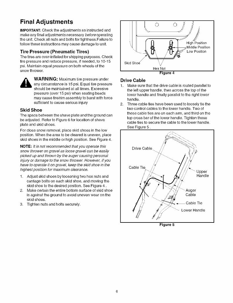
Final AdjustmentsIMPORTANT: Check the adjustments as instructed andmake any final adjustments necessary before operatingthe unit. Check all nuts and bolts for tightness.Failure tofollow these instructions may cause damage to unit.
Tire Pressure (Pneumatic Tires)The tires are over-inflated for shipping purposes. Checktire pressure and reduce pressure, if needed, to 10-15psi. Maintain equal pressure on both wheels of thesnow throwe r.
_ WARNING: Maximum tire pressure underany circumstance is 15 psi. Equal tire pressureshould be maintained at all times. Excessivepressure (over 15 psi) when seating beadsmay cause tire/rim assembly to burst with forcesufficient to cause serious injury
Skid Shoe
The space between the shave plate and the ground canbe adjusted. Refer to Figure 6 for location of shaveplate and skid shoes.
For close snow removal, place skid shoes in the lowposition. When the area to be cleared is uneven, placeskid shoes in the middle or high position. See Figure 4.
NOTE: It is not recommended that you operate thissnow thrower on gravel as loose gravel can be easilypicked up and thrown by the auger causing personalinjury or damage to the snow thrower. However, if youhave to operate it on gravel, keep the skid shoe in thehighest position for maximum clearance.
1. Adjust skid shoes by loosening two hex nuts andcarriage bolts on each skid shoe, and moving theskid shoe to the desired position. See Figure 4.
2. Make certain the entire bottom surface of skid shoeis against the ground to avoid uneven wear on theskid shoes.
3. Tighten nuts and bolts securely.
o o
PositionMiddle PositionLow Position
Skid
Hex NutFigure 4
Drive Cable
1. Make sure that the drive cable is routed parallel tothe left upper handle, then across the top of thelower handle and finally parallel to the right lowerhandle.
2. Three cable ties have been used to loosely tie thetwo control cables to the lower handle. Two ofthese cable ties are on each arm, and third on thetop cross bar of the lower handle. Tighten thesecable ties to secure the cable to the lower handle.
See Figure 5.
Drive Cable_
Cable Tie
Handle
_AugerCable
•,Cable Tie
Lower Handle
Figure 5

Read this owner's manual and safety rules before operating your snow thrower. Compare illustration below withyour snow thrower to familiarize yourself with the location of various controls and adjustments.
Operating Controls(See Figure 6 )
Auger Control
Starter Rope_\
Chute
Upper Handle
Drive ControlOil Fill/
M" Dipstick
UTHer I
Spark |Plug _.
Carburetor
Gas
°ip\.
\\\
\\
Knob
ShEPlate
Auger _
ChuteAssembly
Clean-Out Tool
Shoe
Choke /
Ignition _
KegOil Drain
RecoilStarter
\\
Primer
Throttle Control
Figure 6
Drive Control
Located on the underside of the upper handle, the drivecontrol is used to engage/disengage wheels. Squeeze thedrive control against the upper handle to engage the wheels;release to disengage.
Chute Handle
The direction of snow throwing corresponds to thedirection of the chute opening. Use the chute handle toturn the chute assembly in the direction you wish tothrow snow.
Auger ControlThe auger control is adjacent to the upper handle.Squeeze the auger control against the upper handle toengage the augers; release to disengage the augers.
WAR N ING: Never make adjustments to thechute assembly unless both auger and drivecontrols are disengaged and you are standingbeside the equipment.
IMPORTANT:Refer to AugerControlTeston page 9 prior tooperating your snow thrower. Read and follow allinstructions carefully and perform all adjustments toverify your snow thrower is operating safely andproperly.
Chute Knob
The distance snow is thrown can be adjusted by eitherraising or lowering the upper chute. Loosen the chuteknob on the side of the upper chute to adjust. Pivot theupper chute to desired position, and retighten the chuteknob.
Throttle Control
The throttle control is located on the engine. It regulatesthe speed of the engine and also stops the engine.
Ignition KeyThe ignition key is necessary for the engine to start.Insert key and snap in place; do not turn it to start/stopthe unit. Remove key when the unit is not in use.

Skid Shoe
The space between the shave plate and the ground canbe adjusted. For close snow removal, place skid shoesin the low position. Use middle or high position whenarea to be cleared is uneven or on gravel surfaces.
Before Starting Engine
Engine OilThe unit is shipped with oil in engine. Follow the stepsbelow before starting engine each time.
1. Remove the dipstick from the oil fill. For location ofthe oil fill, see Figure 6.
2. Check and make sure that the level of oil is up tothe FULL mark on the dipstick.
3. If the oil level is not up to FULL, pour fresh oil slowlythrough the plug. Replace dipstick and check oillevel again.
Gasoline
_ ARNING: Since gasoline is flammable,use caution when handling or storing it. Do notfill fuel tank while the engine is running, when itis hot or in an enclosed area. Keep your snowthrower away from any open flame or anelectrical spark and do not smoke duringfueling.
IMPORTANT: Your snow thrower isequipped with a plastic fuel tank insert forshipping purposes. Please discard it atthis time.
A. Electric StarterThe snow thrower engine is equipped with a 120 voltA.C. electric starter and recoil starter. The electric
starter is equipped with a three-wire power cord andplug and is designed to operate on 120 volt AChousehold current.
Cold Start
1. Determine whether your house wiring is a three-wire grounded system. Ask a licensed electrician ifyou are not certain.
_ ARNING: The electric starter must beproperly grounded at all times to avoid thepossibility of electric shock to the operator. Ifyour house wiring system is not a three-wiregrounded system, do not use this electric starterunder any conditions.
2. If your house wiring system is grounded and athree-hole receptacle is not available at the pointthe snow thrower starter will normally be used, oneshould be installed by a licensed electrician.
NOTE: When connecting the power cord, alwaysconnect cord to starter on engine first, then plug theother end into a three-hole grounded 120 Voltreceptacle. When disconnecting the power cord,always unplug the end from the three-hole, groundedreceptacle first.
3.
4.
• Always use clean, fresh, unleadedgrade automotive gasoline.
• Avoid using alcohol blended fuels which can attract 6.moisture and damage fuel system if left in tank 7.during storage. See Off-Season Storage section on 8.page 15. 9.
CAUTION: Never use engine or carburetor cleaner 10.products in the fuel tank.
• Fill the fuel tank outdoors and use a funnel or spout 11.to prevent spilling. The gasoline container shouldbe clean and free of rust or other foreign particles.
• Never fill the fuel tank completely. Fill the tank to no 12.more than 1/2 inch below bottom of filler neck to
provide space for expansion of fuel.• Wipe off any spilled fuel before starting the engine.
To Start Engine
_ ARNING: Be sure no one other than theoperator is standing near the snow throwerwhile starting or operating. Do not operate thissnow thrower unless the chute assembly hasbeen properly installed.
• For location of engine controls, see Figure 6.
Attach spark plug wire to spark plug.Make sure that the auger control and the drivecontrol are disengaged.Remove the keys from the plastic bag. Push keyinto the ignition slot. Do not turn the key. Keepsecond key in a safe place.Move the choke knob to FULL choke position.Move throttle control to the FAST position.Turn fuel valve on, if so equipped.Connect power cord to the switch box on engine.Plug the other end of the power cord into a three-hole, grounded 120 volt A.C. receptacle.Push primer button three times,making sure to cover vent holewhen pushing.Push down on the electric starter
button until the engine starts. Donot crank for more than 5seconds at a time.
_ ARNING: Severe damage to electricstarter is possible if you continue to crank formore than 5 seconds without a cool-down.
13. When the engine starts, release the starter buttonand slowly rotate the choke to OFF position. If theengine falters, rotate the choke to FULL and thengradually to OFF.

NOTE:When engaging the electric starter, a slighthesitation of a few seconds may occur before theengine starts to turn. This is normal and is not harmfulto the engine.
14. Disconnect the power cord from the receptacle firstand then from the switch box on the engine.
15. Allow the engine to warm up for a few minutesbecause the engine will not develop full power untilit reaches operating temperature. Operate at FULLthrottle when throwing snow.
NOTE: If the starter motor runs but the engine does notturn over, the starter gear may have frozen. Place thesnow thrower in a warmer part of the garage till the gearis free of the accumulated ice.
Warm Start
If restarting a warm engine, rotate choke to OFFinstead of FULL and press the starter button. Do notpush the primer button.
B. Recoil StarterMake sure that the auger control and the drive controlare released.
Cold Start1. Move throttle control to FAST position.2. Turn fuel valve on, if so equipped.3. Push key into the ignition slot so that it snaps into
place. Do not turn key. Remove plastic bag andkeep the second key in a safe place.
4. Rotate choke control to FULL choke position.5. Push the primer button while
covering the vent hole. Removeyour finger from the primerbetween primes. Do not prime if
temperature is above 50° F.Prime two times when
temperature is between 50°F and15°F and four times below 15°F.
6. Grasp starter handle and pull rope out slowly untilengine reaches start of compression cycle (ropewill pull slightly harder at this point). Let the roperewind slowly.
7. Pull rope with a rapid, continuous, full arm stroke.Keeping a firm grip on the starter handle, let therope return to the starter slowly. Repeat untilengine starts
8. As the engine warms up, rotate the choke knobslowly to OFF position. If the engine falters, returnto FULL choke, then slowly move to OFF chokeposition.
9. Allow the engine to warm up for a few minutesbecause the engine will not develop full power untilit reaches operating temperature.
10. Operate the engine at full throttle (FAST) whenthrowing snow.
Frozen Recoil Starter
If the starter is frozen and will not turn the engine,proceed as follows:
1. Pull as much rope out of the starter as possible.2. Release the starter handle and let it snap back
against the starter.3. If the engine still fails to start, repeat the first two
steps. If continued attempts do not free starter,follow the electric starter procedures to start.
NOTE: Avoid freezing of the recoil starter by referring toinstructions in the section "Before Stopping".
Warm Start
If restarting an engine after a temporary shut- down,rotate choke to OFF instead of FULL and do not prime.Pull the starter handle as instructed before.
Before Stopping1. Run engine for a few minutes to help dry off any
moisture on engine.2. To avoid possible freeze-up of the starter, follow
these steps:
Recoil Starter
a. With the engine running, pull the starter ropewith a rapid, continuous full arm stroke threeor four times.
Electric Starter
a. Connect power cord to switch box, then to120 Volt AC receptacle.
b. While the engine is running, push the starterbutton and spin the starter for severalseconds.
c. Disconnect power cord from the receptaclefirst, then from the snow thrower.
NOTE: The unusual sound from pulling the starter ropeor from spinning the starter will not harm the engine.
To Stop The Snow Thrower1. While standing inthe operator's position (behind the
snow thrower), engage the auger control for a fewseconds to clear any remaining snow and ice from thechute assembly.
2. To stop the wheels, release the drive control.3. To stop throwing snow, release the auger control.4. To stop engine, push throttle control lever to OFF
and pull out the key. Do not turn key.
_lb ARNING: The temperature of muffler andthe surrounding areas may exceed 150 ° F.Avoid these areas.
Auger Control TestIMPORTANT: Perform the following test beforeoperating the snow thrower for the first time and at thestart of each winter season.

Checktheadjustmentoftheaugercontrolasfollows:• Whentheaugercontrolis releasedandinthe
disengaged"up"position,thecableshouldhaveverylittleslack,butshouldNOTbetight.
,_ WARNING: Do not over-tighten the cable.Over-tightening may prevent the auger fromdisengaging and compromise the safety of thesnow thrower.
• In a well-ventilated area, start the snow throwerengine as instructed earlier in this section under theheading StartingEngine.Make sure the throttle is setin the FAST position.
• While standing in the operator's position (behindthe snow thrower) engage the auger.
• Allow the auger to remain engaged forapproximately ten (10) seconds before releasingthe auger control. Repeat this several times.
• With the engine running in the FAST position andthe auger control in the disengaged "up" position,walk to the front of the machine.
• Confirm that the auger has completely stoppedrotating and shows NO signs of motion.
IMPORTANT: If the auger shows ANY signs of rotating,immediately return to the operator's position and shutoff the engine. Wait for all moving parts to stop beforereadjusting the auger control cable as shown in the"Adjustments" on page 14.
Clearing the SnowCAUTION: Check the area to be cleared for foreignobjects. Remove, if any.
1. Start the engine following Starting instructions.2. Rotate the chute assembly to the desired direction,
away from bystanders and/or buildings.3. Making certain no bystanders or obstacles are in
front of the unit, squeeze the auger controlcompletely against the upper handle to fully engagethe augers.
4. While the auger control is engaged, squeeze thedrive control completely against the upper handleto engage the wheels.
5. As the snow thrower starts to move, maintain a firmhold on the handle, and guide the snow throweralong the path to be cleared.
6. Release the auger and drive controls to stop thesnow throwing action and forward motion.
NOTE: Your unit is equipped with a clutch in thetransmission. If the wheels stop turning while trying todischarge large volumes of snow, immediatelydisengage drive control and allow rotating augers todischarge snow from the housing. Continue operationon a narrower stretch with less volume of snow.
Operating Tips
NOTE: Allow the engine to warm up for a few minutesas the engine will not develop full power until it reaches
operating temperature.
_ ARNING: The temperature of muffler andsurrounding areas may exceed 150° F. Avoidthese areas.
• For most efficient snow removal, remove snowimmediately after it falls.
• Discharge snow downwind whenever possible.Slightly overlap each previous swath.
• Set the skid shoes 1/4" below the shave plate fornormal usage. The skid shoes may be adjustedupward for hard-packed snow.
NOTE: It is not recommended that you operate thissnow thrower on gravel as loose gravel can be easilypicked up and thrown by the auger causing personalinjury and/or damage to the snow thrower.
• If for some reason, you have to operate the snowthrower on gravel, keep the skid shoe in the highestposition for maximum clearance between theground and the shave plate.
• Clean the snow thrower thoroughly after each use.
Clean-Out Tool
_ WARNING: Stop engine by moving throttlelever to stop position and wait for ALL movingparts to stop, before using the clean-out tool.
The clean-out tool is conveniently fastened to the rear of theauger housing with a mounting clip.
When snow and ice collect in the chute assembly duringoperation, use this tool to safely clean the chute and chuteopening. Follow the steps below to operate it:
1. Release both auger and drive control.2. Stop the engine by moving throttle lever to stop
position.3. Remove the clean-out tool from the clip which secures
it to the rear of the auger housing.4. Use the shovel-shaped end of the clean-out tool to
dislodge and scoop any snow and ice which hasformed in and near the chute assembly.
_ WARNING: Never use your hands to cleansnow and ice from the chute assembly or augerhousing.
5. Re-fasten the clean-out tool to the mounting clip on therearof the auger housing.You can now re-start the snowthrower's engine for more snow cleaning.
7. On each succeeding pass, readjust the chuteassembly to the desired position and slightlyoverlap the previously cleared path.
10

General Recommendations• Always observe safety rules when performing any
maintenance.• The warranty on this snow thrower does not cover
items that have been subjected to operator abuseor negligence. To receive full value from thewarranty, operator must maintain the snowthrower as instructed in this manual.
• Some adjustments will have to be madeperiodically to maintain your unit properly.
• All adjustments in the Service and Adjustmentssection of this manual should be checked at leastonce each season.
• Follow maintenance schedule on this page.• Periodically check all fasteners and make sure
these are tight.
_ ARNING: Always stop the engine anddisconnect the spark plug wire beforeperforming any maintenance or adjustments.
Maint. Tasks
Product:
Lubricate pivot points
Check V belts
Engine:
Check engine oil
Change engine oil
Check spark plug
Replace spark plug
Empty fuel system
4
Maintenance Schedule
4
Every 25hours
operation
4
4
Every100 hrs.
operation
4
Service Dates
Checking Oil Level1. Before operating snow thrower, check the oil level.2. With engine on level ground, oil must be to FULL
mark on dipstick. See Figure 7.
A_"_ DipstickRead oil
Figure 7
3. Stop engine and wait several minutes beforechecking oil level. Remove oil fill cap and dipstick.
4. Wipe dipstick clean, insert it into oil fill hole andtighten securely.
5. Remove dipstick and check. If oil is not up to theFULL mark on dipstick, add oil.
Changing OilChange engine oil after first two hours of operation andevery 25 hours thereafter.
In order to change oil, you will have to first drain theused engine oil from the engine and then refill with freshoil.
1. Drain oil while engine is warm. Remove oil drainplug located at the bottom of the recoil starter of theengine. Catch oil in a suitable container.
2. When engine is drained of all oil, replace drain plugsecurely.
3. Remove the dipstick from the oil fill. For location ofthe oil fill, see Figure 6. Pour fresh oil slowlythrough the plug. Replace dipstick.
4. Check and make sure that the level of oil is up tothe FULL mark on the dipstick.
11

Spark PlugClean spark plug and reset the electrode gap to 0.030"at least once a season or every 100 hours of operation;replace every 200 hours of operation.
• Clean area around the spark plug base.• Remove and inspect the spark plug.• Replace the spark plug if electrodes are pitted,
burned, orthe porcelain is cracked. See Figure 8.
NOTE: Do not sandblast spark plug. Spark plug shouldbe cleaned by scraping or wire brushing and washingwith a commercial solvent.
Electrodes
.030" PorcelainGap
Figure 8
LubricationFor a view of the lubrication points on the snow thrower,see Figure 9.1. Lubricate pivot points on the auger control and
drive control with a light engine oil once a season.2. Lubricate the auger idler bracket with a light engine
oil once a season
Lube
,Lube here
Figure 9
Check V-BeltsFollow instructions below to check condition of drivebelts every 25 hours of operation.1. Remove the plastic belt cover on the front of the
engine by removing the self-tapping screw andpressing the plastic tabs to release the belt cover.
2. Visually inspect for frayed, cracked, or excessivelyworn out belts. Replace, if necessary, followinginstructions on page 13.
12

WARNING: Always stop the engine of thesnow thrower, disconnect spark plug wire andmove it away from the spark plug beforeperforming any adjustments or repairs.
WARNING: Never attempt to clean thechute assembly or make any adjustments whilethe engine is running. Always wear safetyglasses during operation or while performingany adjustments or repairs.
Shave Plate & Skid ShoesThe shave plate and skid shoes on the bottom of thesnow thrower are subject to wear. They should bechecked periodically and replaced when necessary.1. Remove the four carriage bolts, and hex nuts which
attach skid shoes to the snow thrower on two sides.
See Figure 10.2. Reassemble new skid shoes with the four carriage
bolts, and hex nuts. Make certain the skid shoesare adjusted to be level.
3. To remove shave plate, remove skid shoe and restof the hardware including carriage bolts, and hexnuts which attach shave plate to the snow throwerhousing. For location of shave plate, see Figure 10.
4. Reassemble new shave plate, making sure headsof the carriage bolts are to the inside of the housing.Reinstall skid shoe. Tighten securely.
Shear PinCotter Pin
Skid
/Shoe
CarriageSha/ve Hex Carria _AgeBoltPlate Nut Bolt
Figure 10
AugersThe augers are secured to the spiral shaft with fourshear pins and cotter pins. See Figure 10. If you hit aforeign object or ice jam, the snow thrower is designedso that the pins may shear.
If the augers do not turn, check to see if the pins havesheared. Replace, if needed, with proper shear pins.refer to item 22 on page 22 for part number.
IMPORTANT: NEVER replace the auger shear pins withstandard pins or fasteners. Any damage to the augergearbox or other components, as a result of doing so,will NOT be covered by your snow thrower's warranty.
Replacing Belts
NOTE: There are two belts on this snow thrower: augerbelt and drive bell It is recommended that both belts be
replaced at the same time.
1. Remove the spark plug wire from the spark plugand ground it against the engine.
2. Drain gasoline from the gas tank, or place a pieceof plastic sheet underneath the gas cap to preventgasoline leakage.
3. Remove the self-tapping screw shown in Figure 11,and press the plastic tabs to release the belt cover.Pull the belt cover out from around the engine andthe chute. Remove it away and save.
Belt Cover/
LppingScrew
Figure 11
Auger Belt1. Slip the front auger belt off the engine pulley
pushing it down between the idler bracket and theengine pulley. See Figure 12.
2. Squeeze the auger control to release tension onthe auger belt; remove the belt.
3. Replace with new belt after replacing the drive belt.Follow instructions in the next page to replace thedrive belt.
13

Drive Belt\
\\
Engine Pulley
Auger Belt
)___Auger Pulley
_ Idler Bracket
Figure 12
Drive Belt
NOTE: Replace the drive belt before reassembling thenew auger belt.
1. Tip the snow thrower up and forward so that it restson the auger housing.
2. Remove the spring that connects the transmissionto a bolt on the engine frame. See Figure 13.
\\
\Spring (shownremoved fromtransmission)
iger PulleyDrive Belt
NOTE: Transmission shown pushed forwardFigure 13
3. Pivot the transmission forward to release pressureon the drive belt. Remove from transmission pulley.
4. Remove the drive belt from around the enginepulley, and away from the unit.
5. Place the new drive belt into the groove on theengine pulley. See Figure 12.
6. Tilt the transmission forward and position the drivebelt on the drive pulley.
7. Reconnect the spring to the bolt on the engineframe and secure the transmission.
8. Reassemble the belt cover on the snow thrower.
Adjustments
Auger CablePeriodic adjustment to the auger control cable may berequired due to normal stretch and wear on the belt.Adjustment is needed if the augers seem to hesitate whileturning, but the engine maintains speed, orcontinue turningwith the auger control disengaged.
1. Remove the self-tapping screw and press the tabsthat secure the belt cover to the snow thrower
housing. Pull the belt cover from around the engineand chute and keep it away. You can now accessthe auger cable.
2. Tighten two hex nuts on the auger cable towardsthe spring to increase the tension on the auger belt.See Figure 14.
3. Reassemble the belt cover.4. Start engine and verify auger control engages and
disengages properly.
NOTE: If auger continues to rotate with the controldisengaged, shut off engine and readjust.
Washer ..Belt Cover _-
Nut
Figure 14
Skid Shoe
Refer to page 6 for details.
14

If the snow thrower will not be used for 30 days orlonger, or if it is the end of the snow season when thelast possibility of snow is gone, the equipment needs tobe stored properly. Follow storage instructions below toensure top performance from the snow thrower formany more years.
Preparing Engine
_ ARNING: Never store snow thrower withfuel in tank indoors or in poorly ventilatedareas, where fuel fumes may reach an openflame, spark or pilot light as on a furnace, waterheater, clothes dryer or gas appliance.
NOTE: It is important to prevent gum deposits fromforming in essential fuel system parts of the enginesuch as the carburetor, fuel filter, fuel hose or tankduring storage.
CAUTION: Alcohol blended fuels (called gasohol orusing ethanol or methanol) can attract moisture whichleads to separation and formation of acids duringstorage. Acidic gas can damage the fuel system of anengine while in storage.
To avoid engine problems, the fuel system shouldbeemptiedbefore storage for 30 days or longer. Followthese instructions to prepare your snow thrower forstorage:
_ WARNING: Drain fuel into an approvedcontainer outdoors, away from any open flame.Be certain engine is cool. Do not smoke. Fuelleft in engine during warm weather deterioratesand will cause serious starting problems.
1. Remove all gasoline from the carburetor and thefuel tank to prevent gum deposits from forming onthese parts and harming the engine.
2. Run the engine until the fuel tank is empty and itstops due to lack of fuel.
3. Drain carburetor by pressing upward on bowl drain,located below the carburetor cover. See Figure 15.
_ ARNING: Do not drain carburetor if usingfuel stabilizer. Never use engine or carburetorcleaning products in the fuel tank or permanentdamage may occur.
Carburet__
Drain
Figure 15
NOTE: Fuel stabilizer (such as STA-BIL) is anacceptable alternative in minimizing the formation offuel gum deposits during storage. Add stabilizer togasoline in fuel tank or storage container. Always followmix ratio found on stabilizer container. Run engine atleast 10 minutes after adding stabilizer to allow it toreach the carburetor. Do not drain carburetor if usingfuel stabilizer.
4. Remove the spark plug and pour one (1) ounce ofengine oil through the spark plug hole into thecylinder. Cover spark plug hole with a rag andcrank the engine several times to distribute the oil.Replace spark plug.
Preparing Snow Thrower1. When storing the snow thrower in an unventilated
or metal storage shed, care should be taken torustproof the equipment. Using a light oil orsilicone, coat the equipment, especially any chains,springs, bearings and cables.
2. Remove all dirt from exterior of engine andequipment.
3. Follow lubrication recommendations on page 11.4. Store equipment in a clean, dry area.
15
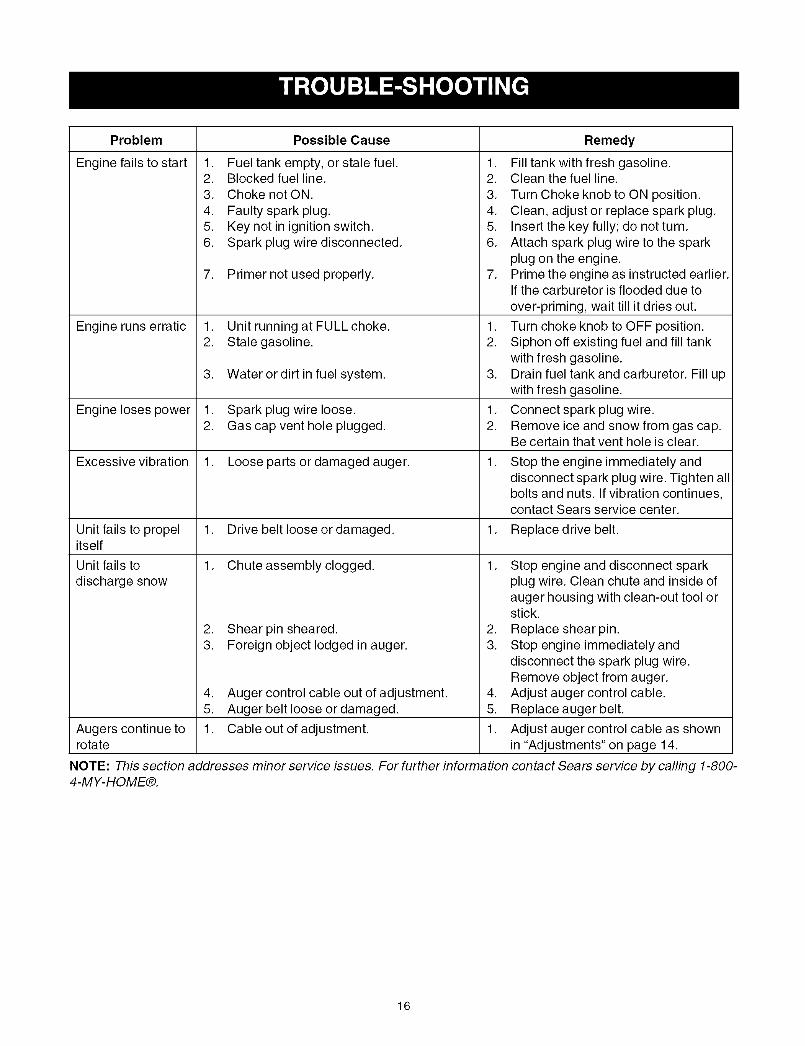
Problem
Engine fails to start 1.2.3.4.5.6.
7.
Engine runs erratic 1.2.
3.
Engine loses power 1.2.
Excessive vibration 1.
Unit fails to propel 1.itself
Unit fails to 1.
discharge snow
2.3.
4.5.
Augers continue to 1.rotate
Possible Cause
Fuel tank empty, or stale fuel.Blocked fuel line.Choke not ON.
Faulty spark plug.Key not in ignition switch.Spark plug wire disconnected.
Primer not used properly.
Unit running at FULL choke.Stale gasoline.
1.
2.3.4.5.6.
7.
1.
2.
Water or dirt in fuel system. 3.
Spark plug wire loose. 1.Gas cap vent hole plugged. 2.
Loose parts or damaged auger. 1.
Drive belt loose or damaged. 1.
Chute assembly clogged. 1.
Shear pin sheared.Foreign object lodged in auger.
Auger control cable out of adjustment.Auger belt loose or damaged.
Cable out of adjustment.
2.
3.
Remedy
Fill tank with fresh gasoline.Clean the fuel line.
Turn Choke knob to ON position.Clean, adjust or replace spark plug.Insert the key fully; do not turn.Attach spark plug wire to the sparkplug on the engine.Prime the engine as instructed earlier.If the carburetor is flooded due to
over-priming, wait till it dries out.
Turn choke knob to OFF position.Siphon off existing fuel and fill tankwith fresh gasoline.Drain fuel tank and carburetor. Fill upwith fresh gasoline.
Connect spark plug wire.Remove ice and snow from gas cap.Be certain that vent hole is clear.
Stop the engine immediately anddisconnect spark plug wire. Tighten allbolts and nuts. If vibration continues,contact Sears service center.
Replace drive belt.
4.
5.
1.
NOTE: This section addresses minor service issues. For further information4-MY-HOME®.
Stop engine and disconnect sparkplug wire. Clean chute and inside ofauger housing with clean-out tool orstick.
Replace shear pin.Stop engine immediately anddisconnect the spark plug wire.Remove object from auger.Adjust auger control cable.Replace auger belt.
Adjust auger control cable as shownin "Adjustments" on page 14.
contact Sears service by calling 1-800-
16

Safety & Decorative Labels: Location and Part Number
777122164
OPERATOR'S
7771221 38
REF. 777S32236MOLD-IN GRAPHIC
777S32066777D08399
17
I. 12
14\\
17\
26
6\\\\
\\
\\\25
19
\\'27
\
23
22
_29
18
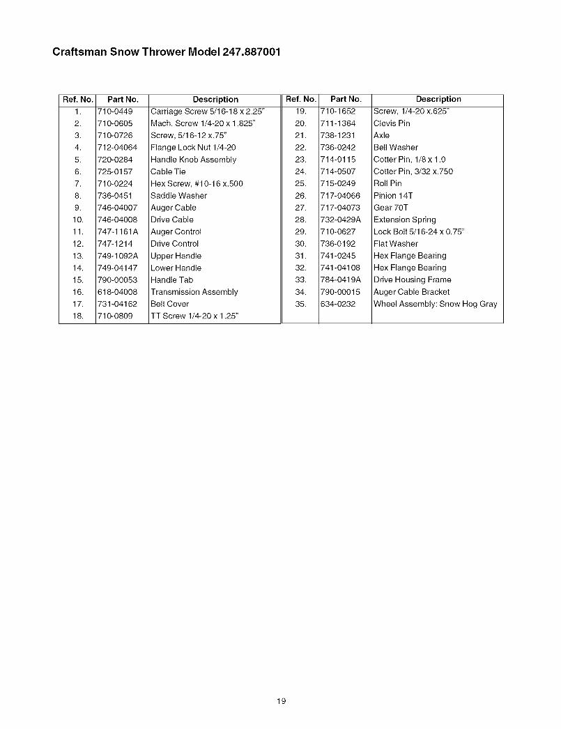
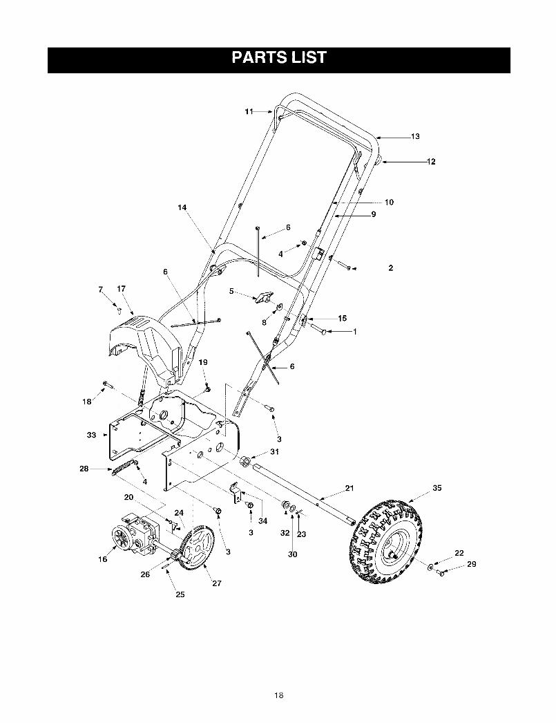
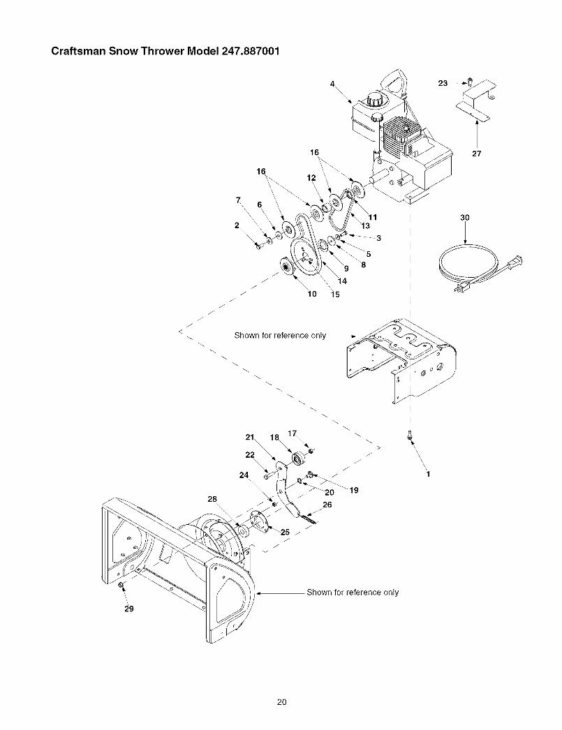
Craftsman Snow Thrower Model 247.887001
Ref. No. Part No.
1. 710-0449
2. 710-0605
3. 710-0726
4. 712-04064
5. 720-0284
6. 725-0157
7. 710-0224
8. 736-0451
9. 746-04007
10. 746-04008
11. 747-1161A
12. 747-1214
13. 749-1092A
14. 749-04147
15. 790-00053
16. 618-04008
17. 731-04162
18. 710-0809
Description
Carriage Screw 5/16-18 x 2.25"
Mach. Screw 1/4-20 x 1.825"
Screw, 5/16-12 x.75"
Flange Lock Nut 1/4-20
Handle Knob Assembly
Cable Tie
Hex Screw, #10-16 x.500
Ref. No.
19.
20.
21.
22.
23.
24.
25.
Part No.
710-1652
711-1364
738-1231
736-0242
714-0115
714-0507
715-0249
Description
Screw, 1/4-20 x.625"
Clevis Pin
Axle
Bell Washer
Cotter Pin, 1/8x 1.0
Cotter Pin, 3/32 x.750
Roll Pin
Saddle Washer
Auger Cable
Drive Cable
Auger Control
Drive Control
Upper Handle
Lower Handle
Handle Tab
Transmission Assembly
Belt Cover
TT Screw 1/4-20 x 1.25"
26.
27.
28.
29.
30.
31.
32.
33.
34.
35.
717-04066
717-04073
732-0429A
710-0627
736-0192
741-0245
741-04108
784-0419A
790-00015
634-0232
Pinion 14T
Gear 70T
Extension Spring
Lock Bolt 5/16-24 x 0.75"
Fiat Washer
Hex Flange Bearing
Hex Flange Bearing
Drive Housing Frame
Auger Cable Bracket
Wheel Assembly: Snow Hog Gray
19
Craftsman Snow Thrower Model 247.887001
4
\\\\
16 27
12
JJ
JJ
28
Shown for reference only
21\\\
22 \
24
>J
\\\\
\
'1
30
Shown for reference only
2O

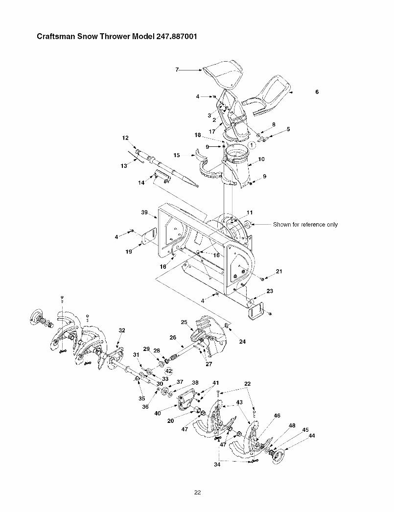
Craftsman Snow Thrower Model 247.887001
Ref. No. Part No.
1. 710-0654A
2. 710-0696
3. 710-1245B
4.
5. 736-0242
6. 736-0247
7. 736-0331
8. 736-0505
9. 736-0507
10. 748-0360
11. 750-1355
12. 750-1356
13. 754-04013
14. 754-04014
15. 756-04024
16. 756-0569
17. 712-3000
18. 756-04035
19. 738-0281
20. 736-0174
21. 784-0434
22. 710-0520
23. 710-0456
24. 712-04063
25. 790-00075
26. 732-0611
27. 790-00064
28. 741-0309
29. 712-04065
30. 629-0071
Description
TT Sems Screw 3/8-16 x 1.0"
Hex Bolt 3/8-24 x 0.875"
Lock Bolt 5/16-24 x 0.875"
Engine
Bell Washer,.340 x.872 x.060
Flat Washer,.4061D x 1.25OD
Bell Washer,.390 x 1.13 x.062
Flat Washer,.341D x 1.50OD
Special Washer, 1.285 x 2.0 x.119
Pulley: Adapter,.75 Dia.
Spacer,.87601D x 1.25OD x.1900
Spacer,.87601D x 1.25OD x.86
V-Belt, 3/8 x 21.108 Lg.
V-Belt, 3/8 x 26.680 Lg.
Auger Pulley
Pulley Half
Hex Lock Nut 3/8-16
Flat Idler
Shoulder Screw 3/8-16
Wave Washer
Auger Idler Bracket
Hex Bolt 3/8-16 x 1.50"
Screw, #10-16 x.500
Flange Lock Nut, 5/16-18
Bearing Housing
Extension Spring
Heat Shield
Ball Bearing
Flange Lock Nut, 3/8-16
Extension Cord: 110V, 3-prong
21
Craftsman Snow Thrower Model 247.887001
12
\
13_
18_ 1
11
Shown for reference only
19
25
3129
\
36
2_\\
20
27
_38 41
47
22
43
21
34
22

Craftsman Snow Thrower Model 247.887001
Ref. No.
1.
2.
3.
4.
5.
6.
7.
8.
9.
10.
11.
12.
13.
14.
15.
16.
17.
18.
19.
20.
21.
22.
23.
24.
25.
PaN No.
684-04037
710-04071
710-0451
712-04063
720-0284
731-04388A
731-04426A
736-0159
712-04064
731-2636A
710-0134
731-2643
725-0157
731-2635
731-04353
710-0451
731-04127
732-04111
784-5580
731-04870
710-0726
738-04124
790-00117
750-04191
731-04218A
Description
Chute Assembly
Carriage Bolt 5/16-18 x 1.0"
Carriage Bolt 5/16-18 x 0.750"
Flange Lock Nut, 5/16-18
Chute Knob Assembly
Chute Handle
Upper ChuteWasher
Flange Lock Nut, 1/4-20
Chute Adapter
Carriage Screw 1/4-20 x 0.62"
Clean-out Tool
Cable Tie
Clean-out Tool Mount
Lower Chute Ring
Carriage Bolt 5/16-18 x 0.75"
Lower Chute
Chute Adjuster Spring
Skid Shoe
Spacer, 1.25OD x.751D x 1.00 Lg.
Ref. No.
26.
27.
28.
29.
30.
31.
32.
33.
34.
35.
36.
37.
38.
39.
40.
41.
42.
43.
Part No.
717-1772A
715-04020
721-0327
741-0662
736-3084
715-04021
721-0325
718-04071
714-04040
741-0663
714-0161
717-0528A
736-0351
684-04089
618-0124
618-0123
710-0642
618-04181
684-04113
684-04114
DescriptionWorm Shaft
Spiral PinOil Seal
Flange Bearing
Flat Washer,.51 x 1.12 x.06
Spiral Pin
PlugThrust Collar
Bow Tie Cotter Pin
Flange Bearing
KeyWorm Gear 20T
Fiat Washer
Auger Housing, 22"
Reducer Housing Assembly LH
Reducer Housing Assembly RHTT Screw 1/4-20 x 0.75"
Auger Gearbox Assembly
Auger Assembly - LH
Auger Assembly - RH
AB Screw 5/16-12
Shear Pin,.25 x 1.50
Shave Plate
Spacer
Impeller
44.
45.
46.
47.
48.
790-00087
741-0245
711-04286
741-0493A
736-0351
Hex Bearing Housing
Hex Flange Bearing
Auger Axle
Flange BushingFlat Washer
23

Craftsman 5 hp. Engine 143.045003 for Snow Thrower Model 247.887001
223
219
>
370B
25 26"/
203
361A
285 93
287 390
370K
24

Craftsman 5 hp. Engine 143.045003 for Snow Thrower Model 247.887001
Key No.
1
2
4
5
14
15
16
17
18
19
20
25
26
3O
40
4O
40
41
41
41
42
42
42
43
45
46
48
49
50
60
64
64A
65
69
70
72
72A
75
80
81
82
83
86
89
90
92
93
Part No.
36469A
26727
30969
28277
31334
37729
31335
651018
30342
32600
36552
650802
37842
36073
36074
36075
36070
36071
36072
36076
36077
36078
20381
32875A
32610A
27241
32654
33158
29745
30063
8345
650128
27677A
34674C
27642
28582
27897
30574A
30590A
30591
30588A
650488
610961
611199
650815
650816
Description Key No.
Cylinder (Incl. 2,20,72,72A & 125) 100
Dowel Pin 101
Oil Drain Extension (purchase locally) 102
Extension Cap 103
Washer 110
Governor Rod 110A
Governor Lever 119
Governor Lever Clamp 120
Screw, T-15, 8-32 x 19/64" 125
Extension Spring 125
Oil Seal 126
Blower Housing Baffle (Incl. 262) 127
Screw, 1/4-20 x 5/8" 130
Crankshaft 130A
Piston, Pin & Ring Set (Std.) 130B
Piston, Pin & Ring Set (.010" OS) 135
Piston, Pin & Ring Set (.020" OS) 150
Piston & Pin Ass'y. (Std.) (Incl. 43) 151
Piston & Pin Ass'y. (.010" OS) (Incl. 43) 169
Piston & Pin Ass'y. (.020" OS) (Incl. 43) 170
Ring Set (Std.) 171
Ring Set (.010" OS) 172
Ring Set (.020" OS) 173
Piston Pin Retaining Ring 174
Connecting Rod Ass'y. (Incl. 46 & 49) 178
Connecting Rod Bolt 181
Valve Lifter 182
Oil Dipper 183
Camshaft (BCR) 184
Blower Housing Extension 185
Screw, T-30, 1/4-20 x 1/2" 186
Washer 200
Screw, 10-24 x 1/2" 203
Cylinder Cover Gasket 204
Cylinder Cover (Incl. 75 thru 83) 206
Oil Plug 209
Oil Drain Plug 209A
Oil Seal 215
Governor Shaft 219
Washer 220
Governor Gear Assembly (Incl. 81) 222
Governor Spool 223
Screw, 1/4-20 x 1-1/4" 224
Flywheel Key 260
Flywheel (W/Ring Gear) 262
Belleville Washer 267
Flywheel Nut 268
PaN No.
34443C
610118
651024
651007
35182
36874
36443
37675
36471
36472
32644A
650691
6021A
650694A
650818
35395
31672
31673
27234A
27666
31410
34146
35350
650783
29752
650870
6201
34583A
26756
33691
32698
36677
31342
651029
610973
650139
30322
35440
34582
35438
28820
650664
33673A
35656A
650737
34212
30200
Description
Solid State Ignition
Spark Plug Cover
Solid State Mounting Stud
Screw, T-15, 10-24 x 15/16"
Ground Wire
Ground Wire
Cylinder Head Gasket
Cylinder Head (Incl. 131)
Exhaust Valve (Std.) (Incl. 151)
Exhaust Valve (1/32" OS) (Incl. 151)
Intake Valve (Std.) (Incl. 151 )Washer
Screw, 5/16-18 x 1-1/2"
Screw, 5/16-18 x 2"
Screw, 5/16-18 x 1-1/2"
Resistor Spark Plug (RJ19LM)
Valve Spring
Valve Spring CapValve Cover Gasket
Breather Body
Breather Element
Valve Cover
Breather Tube
Screw, 10-24 x 3/4"
Nut & Lock Washer, 1/4-28"
Screw, 1/4-28 x 1-11/16"
Screw, 1/4-28 x 7/8"
Choke Bracket
Carburetor To Intake Pipe Gasket
Intake Pipe
Governor Link
Control Bracket (Incl. 203 thru 209A)
Compression Spring
Screw, T-10, 5-40 x 7/16"
Terminal
Screw, 8-32 x 3/4"
Nut & Lock Washer
Control Knob
Choke Rod
Choke Knob
Screw, 10-32 x 1/2"
Screw, 1/4-20 x 1-19/32"
Intake Pipe Gasket
Blower Housing
Screw, 1/4-20 x 1/2"
Hold Down Bracket
Screw, 10-24 x 9/16"
25

Craftsman 5 hp. Engine 143.045003 for Snow Thrower Model 247.887001
Key No.
274
275
277
285
287
29O
292
298
3OO
301
3O5
3O7
308
310
313
328
329
335
338
340
342
342A
343
Part No.
33670A
35771A
792005
36467A
650926
30705
26460
650665
35584
35355
35554
35499
35539
35556
34080
35593
610973
35072
650257
36247
30063
650765
35079A
Description
Exhaust Gasket
Muffler (Incl. 274)
Screw, 1/4-20 x 2-27/64"
Starter Cup
Screw, 8-32 x 21/64"
Fuel Line
Fuel Line Clamp
Screw, 1/4-15 x 3/4"
Fuel Tank (Incl. 292 & 301)
Fuel Cap
Oil Fill Tube
O-Ring
Fill Tube Clip
Dipstick
Spacer
Ignition Key
Terminal
Carburetor Cover
Screw, 8-32 x 5/16"
Fuel Tank Bracket
Screw, T-30, 1/4-20 x 1/2"
Washer
Key Switch Bracket (Incl. 343A)
Key No. Part No.
343A 651060
345 33344
350 570682A
351 32180C
355 590574
361 650738
361A 650561
364 33333
364A 37673
365 650735
370A 36261
370B 35282
370C 36501
370D 35878
3701 36534
370K 36695
380 640084B
390 590742
396 33290E
400 36444
900
900 754337
Description
Screw, 10-32 x 23/64"
Heat Baffle
Primer Assembly
Primer Line
Starter Handle (Mitten Grip)
Screw, 1/4-20 x 5/8"
Screw, 1/4-20 x 19/32"
Carburetor Cover Bracket
Locking Plate
Screw, 10-24 x 3/8"
Instruction Decal
Speed Control Decal
Primer Decal
Warning Decal
Warning Decal
Starter Decal
Carburetor (Incl. 184)
Rewind Starter*
Electric Starter Motor (120 Volt)
Gasket Set (Incl. Items Marked PK inNotes)
Rep. Engine
Rep. Short Block
Note: This engine could have been built with the 590707 starter
Electric Starter 33290E
2925.
30
\13
7
\4
5A
7
Key No. PaN No.2 31749
3 33522
4 33769
5A 37332
6 35461
7 35450
8 35912
9
10A 35452A
13 590500
14 33441
15 35453
16 35454
19 35911
24 35462
25 35456
26 650819
26 651032
29 32450B
30 650759
*NOTE:
Description
Retainer Ring
Spring Retainer
Anti-Drift Spring
Nut & Gear (Incl. 2)
Drive End Cap Ass'y. (Incl. 7)
"O" Ring
Armature
Housing Ass'y. *
Brush & Spring Card Ass'y.Thrust Washer
Ground Screw
Commutator End Cap Ass'y. (Incl. 7)
Switch Box Ass'y.
Thrust Washer
Case Bolt
Grounding Screw
Screw, 6-32 x 2-1/2"
Screw, 12-16 x 5/8"
Extension Cord (10'6")
Screw, Torx T-30, 1/4-20 x 23/32"
Must purchase complete motor
26

Craftsman 5 hp. Engine 143.045003 for Snow Thrower Model 247.887001
Rewind Starter 59070711
,\
13 "_
\\\\:_
\\
/
Key No. PaN No.
1 590599A
2 590600
3 590696
4 590601
5 590697
6 590698
7 590699
8 590709
11 590708
12 590535
13 590574
Description
Spring PinWasher
Retainer
Washer
Brake Spring
Starter Dog
Dog Spring
Pulley & Rewind Spring Assembly
Starter Housing Assembly
Starter Rope
Mitten Grip Handle
Rewind Starter 590742
14_
11.Key No.
3
6
7
8
11
12
13
14
Part No.
590740
590616
590617
590645A
590647A
590535
590574
590760
Description
Retainer
Starter Dog
Dog Spring
Pulley & Rewind Spring Assembly
Starter Housing Assembly
Starter Rope
Mitten Grip Handle
Spring Clip
27
Craftsman 5 hp. Engine 143.045003 for Snow Thrower Model 247.887001
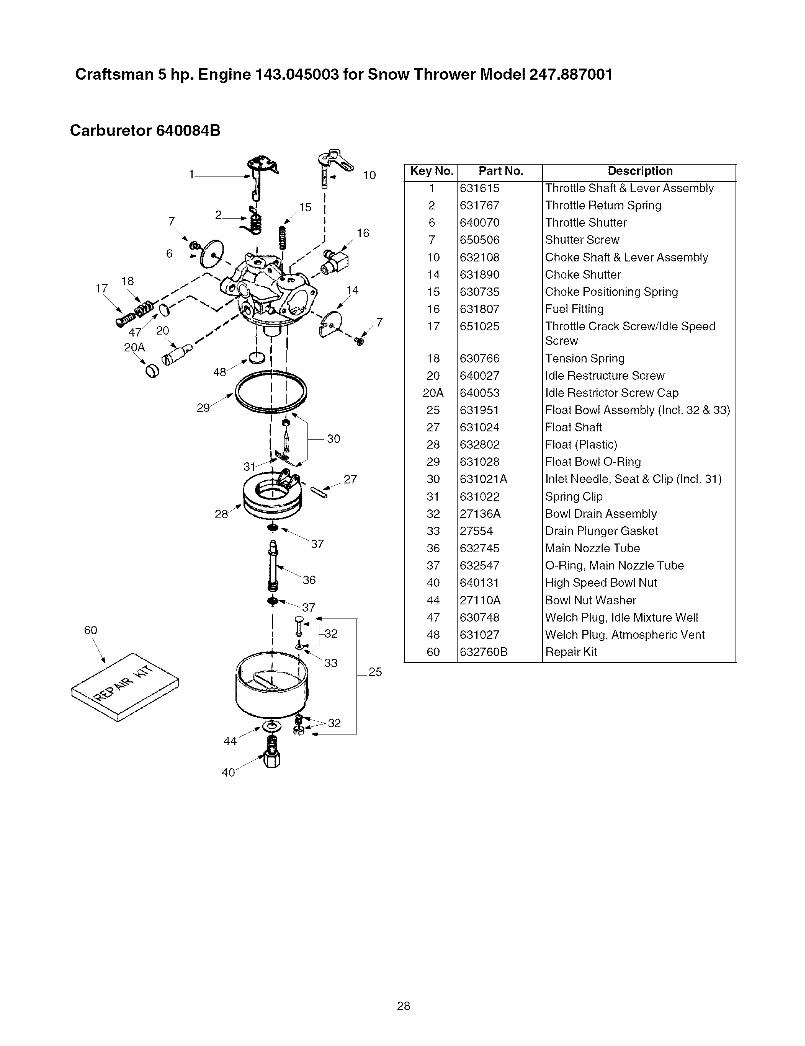
Carburetor 640084B
Key No.
1
2
6
7
10
14
15
16
17
18
2O
20A
25
27
28
29
3O
31
32
33
36
37
4O
44
47
48
6O
Part
631615
631767
640070
650506
632108
631890
630735
631807
651025
630766
640027
640053
631951
631024
632802
631028
631021A
631022
27136A
27554
632745
632547
640131
27110A
630748
631027
632760B
NO. Description
Throttle Shaft & Lever Assembly
Throttle Return SpringThrottle Shutter
Shutter Screw
Choke Shaft & Lever Assembly
Choke Shutter
Choke Positioning Spring
Fuel Fitting
Throttle Crack Screw/Idle SpeedScrew
Tension Spring
Idle Restructure Screw
Idle Restrictor Screw Cap
Float Bowl Assembly (Incl. 32 & 33)
Float Shaft
Float (Plastic)
Float Bowl O-Ring
Inlet Needle, Seat & Clip (Incl. 31)
Spring Clip
Bowl Drain Assembly
Drain Plunger Gasket
Main Nozzle Tube
O-Ring, Main Nozzle Tube
High Speed Bowl Nut
Bowl Nut Washer
Welch Plug, Idle Mixture Well
Welch Plug, Atmospheric Vent
Repair Kit
40_
28
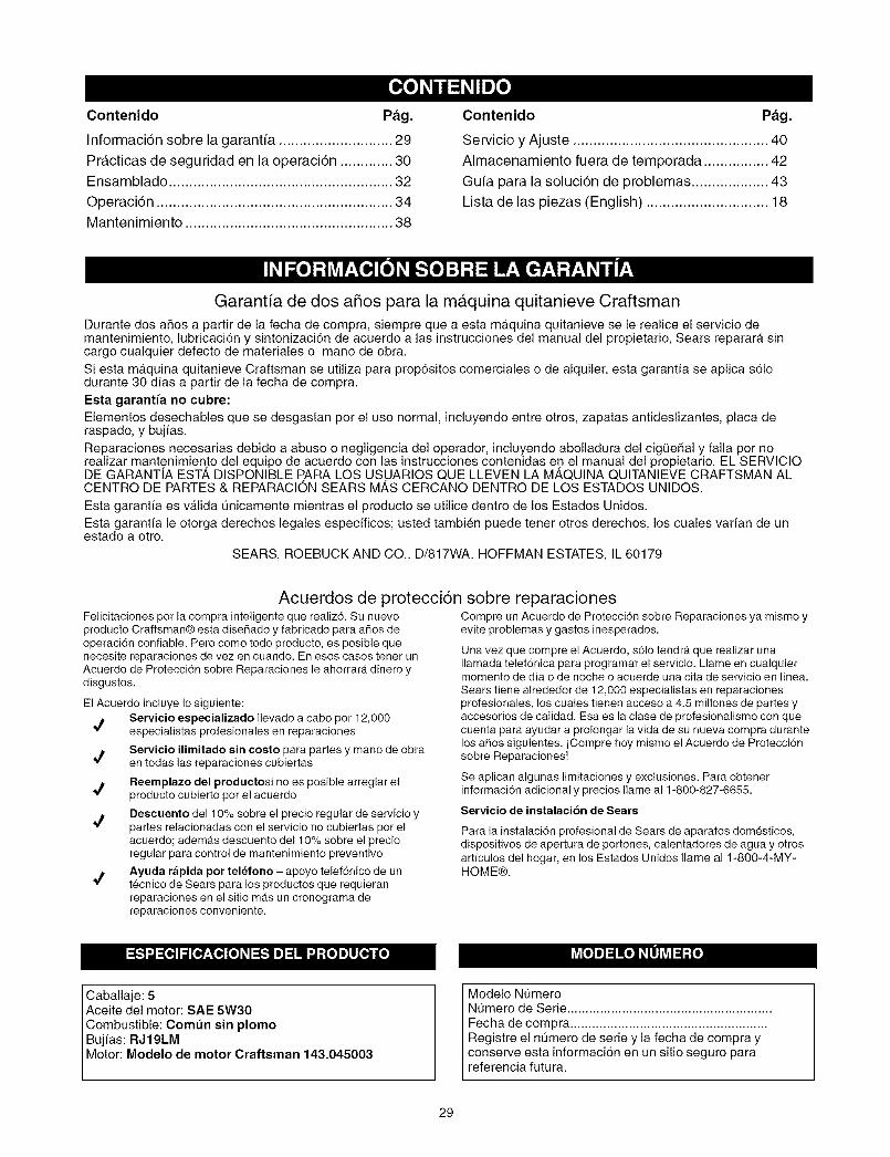
Contenido Pag.
Informaci6n sobre la garantia ............................ 29
Practicas de seguridad en la operaci6n ............. 30Ensamblado ....................................................... 32
Operaci6n .......................................................... 34Mantenimiento ................................................... 38
Contenido Pag.
Servicio y Ajuste ................................................ 40
Almacenamiento fuera de temporada ................ 42
Guia para la soluci6n de problemas ................... 43
Lista de las piezas (English) .............................. 18
Garantia de dos afios para la m&quina quitanieve Craftsman
Durante dos afios a partir de la fecha de compra, siempre que a esta maquina quitanieve se le realice el servicio demantenimiento, lubricaci6n y sintonizaci6n de acuerdo alas instrucciones del manual del propietario, Sears reparara sincargo cualquier defecto de materiales o mano de obra.
Si esta m_tquina quitanieve Craftsman se utiliza para prop6sitos comerciales o de alquiler, esta garantia se aplica s61odurante 30 d(as a partir de la fecha de compra.
Esta garantia no cubre:
Elementos desechables que se desgastan por el uso normal, incluyendo entre otros, zapatas antideslizantes, placa deraspado, y buj(as.
Reparaciones necesarias debido a abuso o negligencia del operador, incluyendo abolladura del cigQefial y falla por norealizar mantenimiento del equipo de acuerdo con las instrucciones contenidas en el manual del propietario. EL SERVICIODE GARANTIA EST, _, DISPONIBLE PARA LOS USUARIOS QUE LLEVEN LA M,_,QUINA QUITANIEVE CRAFTSMAN ALCENTRO DE PARTES & REPARACION SEARS MAS CERCANO DENTRO DE LOS ESTADOS UNIDOS.
Esta garantia es valida t]nicamente mientras el producto se utilice dentro de los Estados Unidos.
Esta garantia le otorga derechos legales especfficos; usted tambien puede tener otros derechos, los cuales varian de unestado a otro.
SEARS, ROEBUCK AND CO., D/817WA, HOFFMAN ESTATES, IL 60179
Acuerdos de protecci6n sobre reparacionesFelicitaciones por la compra inteligente que realiz6. Su nuevoproducto Craftsman@ esta diseflado y fabricado para afios deoperacidn confiable. Pero como todo producto, es posible quenecesite reparaciones de vez en cuando. En esos casos tener unAcuerdo de Proteccidn sobre Reparaciones le ahorrara dinero ydisgustos.
El Acuerdo incluye Io siguiente:Servicio especializado Ilevado a cabo por 12,000
*/ especialistas profesionales en reparaciones
Servicio ilimitado sin costo para partes y mano de obraen todas las reparaciones cubiertas
Reemplazo del productosi no es posible arreglar el*/ producto cubierto per el acuerdo
Descuento del 10% sobre el precio regular de servicio ypartes relacionadas con el servicio no cubiertas por el
acuerdo; adem4s descuento de110% sobre el precioregular para control de mantenimiento preventivo
Ayuda rapida por tel_fono - apoyo telef6nico de un*_ t_cnico de Sears para los productes que requieran
reparaciones en el sitio mas un cronegrama dereparaciones conveniente.
Compre un Acuerdo de Protecci6n sebre Reparaciones ya mismo yevite problemas y gastos inesperados.
Una vez que compre el Acuerdo, s61otendra que realizar unaIlamada telef6nica para programar el servicio. Llame en cualquiermomento de dia o de noche o acuerde una cita de servicio en I(nea.Sears tiene alrededor de 12,000 especialistas en reparacionesprofesionales, los cuales tienen acceso a 4.5 millones de partes yaccesorios de calidad. Esa es la clase de profesionalismo con quecuenta para ayudar a prolongar la vida de su nueva compra durantelos afios siguientes, iCompre hoy mismo el Acuerdo de Protecci6nsobre Reparaciones!
Se aplican algunas limitaciones y exclusiones. Para obtenerinformacidn adicional y precios Ilame al 1-800-827-6655.
Servicio de instalaci6n de Sears
Para la instalacidn profesional de Sears de aparatos dom_sticos,dispositivos de apertura de portones, calentadores de agua y otrosarticulos del hogar, en los Estados Unidos Ilame al 1-800-4-MY-HOME@.
Ikv_[o]m]_1n(o]_,L|Jkv4_1;{o]
Caballaje: 5Aceite del motor: SAE 5W30Combustible: Comt_n sin plomoBuj(as: RJ19LM
Motor: Modelo de motor Craftsman 143.045003
Modelo Nt]meroNOmero de Serie ........................................................Fecha de compra ......................................................Registre el nOmero de serie y la fecha de compra yconserve esta informaci6n en un sitio seguro parareferencia futura.
29
ADVERTENClA: Este simbolo indica instrucciones de seguridad importantes que de no seguirse,podrian poner en peligro la seguridad personal y/o la propiedad suya y de terceros. Lea y siga todas lasinstrucciones en este manual antes de iniciar la operaci6n de esta maquina. En caso de no seguir estasinstrucciones podrian producirse lesiones personales. Cuando vea este simbolo--preste atenci6n a laadvertencia..
_ ADVERTENCIA: El escape del motor de este producto, algunos de sus componentes y algunoscomponentes del vehiculo contienen o emiten productos quimicos que el estado de California consideraque pueden producir c4ncer, defectos de nacimiento u otros problemas reproductivos.
PELIGRO: Esta maquina esta diseSada para set utilizada respetando las reglas de seguridad contenidas en este manual. AIigual que con cualquier tipo de equipo electrico, una falla o error de parte del operador puede producir graves lesiones. Estamaquina es capaz de amputar manos y pies y de arrojar objetos con gran fuerza. De no respetar las instrucciones de seguridadsiguientes se pueden producir lesiones graves o la muerte.
Capacitacion1. Lea, coml)renda y respete todas las instrucciones que figuran
en la maquina o en este(os) manual(es) antes de proceder alensamblado y ol)eraci6n del equil)o. Guarde este manual en unlugar seguro l)ara referencias futuras y regulates y parasolicitar l)artes de reemplazo.
2. Familiarfcese con todos los controles y con su funcionamiento.Sepa c6mo detener la m&quinay c6mo desengranar loscontroles.
3. Nunca permita que niSos menores de 14aSos operen estam_.quina.Los nifios de 14 afios y mayores de 14 aSosdebenleer y comprender las instrucciones de ol)eraci6n y las reglasde seguridad contenidas en este manual y deben serentrenados y supervisados per uno de los padres.
4. Nunca l)ermita que adultos sin los conocimientos adecuadosacerca de la m_.quinala ol)eren.
5. Los objetos arrojados per la maquina l)ueden l)roducir lesionesgraves. Planifique el patr6n en el que va a ir arrojando nievel)ara evitar que la descarga de material se realice hacia loscaminos, los observadores, etc.
6. Mantenga a los observadores, ayudantes, mascotas y a losnifios l)or Io menos a 75 pies de la maquina mientras la mismaesta en funcionamiento. Detenga la m_.quinasi alguien entra enla zona.
7. Sea l)recavido para evitar patinarse o caerse especialmentecuando opera la maquina en reversa.
Preparativos1. Revise minuciosamente la zona donde se utilizar_,el equipo.
Saque todos los felpudos, peri6dicos, trineos, tablas, cables yotros objetos extraSos con los que podria trol)ezar o quepodrfan ser arrojados per la barrena / motor.
2. Para l)rotegerse los ojos utilice siempre anteojos o antil)arrasde seguridad mientras opera la maquJnao mientras la ajusta orel)ara. Los objetos arrojados que rebotan pueden lesionargravemente la vista.
3. No opere la maquina sin la vestimenta adecuada para estar alaire libre en invierno. No utilice alhajas, bufandas largas u otrasl)rendas sueltas que podrian enredarse en las partes m6viles.Utilice uncalzado especial l)ara superficies resbaladizas.
4. Use un cord6n prolongador y un tomacorriente de tres cablescon conexi6n a tierra l)ara todas las unidades con motores conencendido electrico.
5. Ajuste la altura de la caja del tomacorriente para limpiar lagrava o las superficies con l)iedras trituradas.
6. Desengrane todas las l)alancas de embrague antes dearrancar el motor.
7. Nunca intente realizar ajustes mientras el motor esta en
8,
9.
marcha excepto en los casos especMcamente recomendadosen el manual del ol)erador.Deje que el motor y la maquina se adal)ten a la teml)eraturaexterior antes decomenzar a sacar la nieve.Sea sumamente cuidadoso al manipular la gasolina paraevitarlesiones o daSos. Lagasolina es altamente inflamable y losvapores son explosives. Se l)uede lesionar gravemente siderrama gasolina sobre usted o sobre la ropa ya que se puedel)render fuego. Lave la piel y cambiese de rol)a de inmediato.
a. Utilice s6lo recipientes para gasolina al)robados.b. Apague todos los cigarrillos, cigarros, l)il)as y otras
fuentes de combusti6n.c. Nunca cargue combustible en la maquina en un
espacio cerrado.d. Nunca saque la tapa del combustible ni agregue
combustible mientras el motor esta caliente o enmarcha.
e. Deje que el motor se enfrfe per Io menos dos minutosantes de volver a cargar combustible.
f. Nunca recargue el tanque de combustible. Llene eltanque nomas de 1/2 pulgada l)or debajo de la basedel cuello del filtro para dejar espacio para la dilataci6ndel combustible.
g. Vuelva a colocar la tapa de la gasolina y ajt]stela bien.h. Limpie la gasolina derramada sobre el motor y el
equil)o. Traslade la m_.quinaa otra zona. Esl)ere 5minutes antes de encender el motor.
i. Nunca almacene la m_.quinao el recipiente decombustible en un esl)acio cerrado donde haya fuego,chispas o luz piloto (per ejemplo, hornos, calentadoresdeagua, calefactores, secadores de ropa, etc.).
j. Deje que la maquina se enfrie durante 5 minutes antesde almacenarla.
Operacion1. No l)onga las manes o los pies cerca de las piezas rotatorias,
en la caja de la barrena / motor o en el canal de descarga. Elcontacto con piezas rotatorias l)uede aml)utar manesy pies.
2. La palanca del embrague de la barrena / motor es undisl)ositivo de seguridad. Nunca pase por alto sufuncionamiento. De hacerlo la operaci6n de la maquina esriesgosa y puede ocasionar lesiones.
3. Las palancas del embrague deben funcionar bien enambasdirecciones y regresar autom_.ticamentea la posici6n dedesengrane cuando se las suelta.
4. Nunca el)ere la m_.quinasi falta un canal de descarga o elmismo esta daSado. Mantenga todos los dispositivos deseguridad en su lugar yen funcionamiento.
30

5. Nuncaenciendaelmotorenespacioscerradosoenunazonapocoventilada.Elescapedelmotorcontienemon6xidodecarbono,ungasinodoroyletal.
6. NooperelamAquinaestandobajolosefectosdelalcoholodedrogas.
7. Elsilenciadoryelmotorsecalientanyproducenunaquemadura.Nolostoque.
8. Seasumamenteprecavidocuandooperelam_.quinasobreunasuperficiecongravaocuandolacruce.Mantengasealertaporsisepresentanpeligrosocultosotransito.
9. Tengacuidadocuandocambiededirecci6nocuandooperelam_.quinaenpendientes.
10.Planifiqueelpatr6nenelquevaairarrojandonieveparaevitarqueladescargadematerialseproduzcahacialasventanas,lasparedes,losautom6viles,etc.paraevitarposiblesdafiosmaterialesolesionesproducidasporlosrebotes.
11.Nuncadirijaladescargahacialosni_os,losobservadoresylasmascotasnidejequenadieseparedelantedelamaquina.
12.Nosobrecarguelacapacidaddelam_.quinatratandodesacarlanievemuyr_.pidamente.
13.Nuncaopereestamaquinasinotienebuenavisibilidadoiluminacion.Siempredebeestarsegurodequeestabienafirmadoysostengabienlasmanijas.Camine,nuncacorra.
14.Cortelacorrientealabarrena/ motor cuando transporte lam_.quinao cuando la misma no esta en uso.
15. Nunca opere la m_.quinaa alta velocidad de desplazamientosobre superficies resbaladizas. Mire hacia abajo y hacia atras ytenga cuidado cuando la useen reversa.
16. Si la maquina comenzara a vibrar de manera anormal, detengael motor, desconecte el cable de la bujfa y pongala de maneraque haga masa contra el motor. Inspeccione la maquinaminuciosamente para ver siesta dafiada. Repare todos losdafios antes de encender y operar la m_.quina.
17. Desengrane todas las palancas de embrague y detenga elmotor antes de dejar la posici6n de operaci6n (detras de lasmanijas). Espere a que la barrena / motor se detenga porcompleto antes de destapar el canal de descarga, de realizarajustes o inspecciones.
18. Nunca ponga las manos en las aberturas de descarga o derecolecci6n. Utilice siempre la herramienta de limpieza que seadjunta para destapar la abertura de descarga. No destape elcanal dedescarga mientras el motor est6.en marcha. Antes dedestaparlo, apague el motor y permanezca detr_s de lasmanijas hasta que todas las partes moviles se hayan detenidocompletamente.
19. Use s61ouniones y accesorios aprobados por el fabricante (porejemplo, pesas para las ruedas, cadenas para los neum_.ticos,cabinas, etc.).
20. Si se presentan situaciones que no estan previstas enestemanual sea cuidadoso y use el sentido com@. Contacte alcentro de servicio Sears para obtener asistencia.
Mantenimiento & Almacenamiento1. Nunca manipule los dispositivos deseguridad de manera
imprudente. Controle peri6dicamente que funcionen de formaadecuada. Remitase a las secciones de mantenimiento yajuste de este manual.
2. Antes de realizar la limpieza, de reparar o de revisar lam_.quina,desengrane todas las palancas deembrague ydetenga el motor. Espere a que la barrena / motor se detengapor completo. Desconecte el cable de la bujia y p6ngalo demanera que haga masa contra el motor para evitar que seencienda de manera accidental.
3. Verifique frecuentemente que los pernos y tornillos estenajustados correctamente para asegurarse de que la m_.quinaeste trabajando de manera segura. Adem_.srealice unainspeccion visual de la m_.quinapara controlar si la misma estadafiada.
4. No cambie la configuraci6n del regulador del motor ni aceleredemasiado el mismo. El regulador controla la velocidadm_.ximasegura de operacion del motor.
5. Las placas de raspadoy las zapatas antideslizantes que seusan con la maquina quitanieve se desgastan y se dafian. Paraproteger su seguridad, verifique frecuentemente todos loscomponentes y reemplacelos s61oconpartes de los fabricantesde equipos originales (OEM). "La utilizaci6n de partes que nocumplan con las especificaciones de equipos originales podrfatener como resultado un rendimiento incorrecto y ademas laseguridad podrfa estar comprometida"
6. Revise los controles del embrague peri6dicamente paraverificar que engranen y desengranen adecuadamente yajtJstelossi es necesario.Consulte la secci6n de ajustes eneste manual del operador para obtener instrucciones.
7. Mantenga/reemplace lasetiquetas/instrucciones de seguridadsegt]n sea necesario.
8. Respete las leyes y reglamentaciones referentes a ladisposici6n correcta de combustible, aceite, etc. para protegerel medio ambiente.
9. Antes de almacenar la m_.quinaenciendala unos minutos parasacar la nieve que haya quedado en la misma y para evitar asique se congele la barrena / motor.
10. Nunca almacene la m_.quinao el recipiente de combustible enun espacio cerrado donde haya fuego, chispas o luz pilotocomo por ejemplo, calentadores de agua, hornos, secadoresde ropa, etc.
11. Siempre consulte el manual del operador para obtenerinstrucciones correctas acerca del almacenamiento fuera detemporada.
Su responsabilidad:S61opermita que usen esta m_.quinaelectrica las personas quelean, comprendan y respeten las advertencias y las instruccionesque aparecen en este manual yen la m_.quina.A continuaci6n semuestran las etiquetas de seguridad parasu referencia.
No modifique el motorPara evitar lesiones graves o la muerte, no modifique el motorbajo ninguna circunstancia. Si cambia la configuraci6n delregulador el motor puede descontrolarse y operar avelocidades inseguras. Nunca cambie la configuracidn defabrica del regulador del motor.
Aviso referido a emisionesLos motores que esta.n certificados y cumplen con lasregulaciones de emisiones federales EPA y de Californiapara SORE (Equipos Small Off Road Equipment) estancertificados para operar con gasolina comt]n sin plomo ypueden incluir los siguientes sistemas de control deemisiones: Modificacion de motor (EM) y catalizador de tresvias (TWC) siesta equipado de esa manera.
Calcomania de identificaci6n del motorEstacalcomania indica el nL)merodel modelo del motor, lasespecificaciones y lafecha de fabricacidn. Por favor mire lacalcomanfaen el motor de su equipo y registre esa informaci6n parareferencia futura.
Lacalcomaniade identificacidndel motortambienincluyeespecificacionessobreel periodo devida t]tildel motor relacionadoconlasemisiones.Esteperiodoesta.relacionadocon lavida t]til enconformidadcon las emisionessegLinIocertificadopor EPAy/o CARB.Parahallar la especificacidndel periododevida t]til del motor,por favorlea lacalcomaniadel motory ubique la/etra (entrecomillas)entrelaspalabrasModeradoy PeriododeVidaUtil. Conecte unade lassiguientes letrascon la letra impresaensu calcomanfa.Porejemplo,alosmodelosHSSKse los designacomo:
"C" -- 125 horas; "B" -- 250 horas; "A" -- 500 horas
31
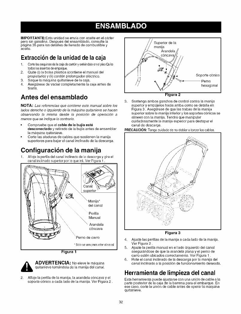
IMPORTANTE:Esta unidad se envfa con aceite en el carterpero sin gasolina. Despues del ensamblado, consulte lapagina 35 para los detalles de Ilenado de combustible yaceite.
Extracci6nde la unidad de la caja1. Cortelasesquinasde lacajadecart6ny extiendalaenel pisoQuite
todoslosinsertosdeempaque.2. Quite (i) la bolsa plastica (contiene el manual del
propietario) y (ii) cord6n prolongador electrico.3. Saque la maquina quitanieve de la caja.4. Asegt]rese de vaciar completamente la caja antes de
tirarla.
Antes del ensamblado
NOTA: Las referencias que contiene este manual sobre loslados derecho o izquierdo de la maquina quitanieve se hacenobservando la misma desde la posicidn de operacidn amenos que se indique Io contrario.
• Compruebe que el cable de la bujia eetedesconectado y retirado de la bujfa antes de ensamblarla maquina quitanieve.
• Corte las ataduras de cables que sostienen la manijasuperiores para bajar el canal inclinado de la descarga.
Configuracibn de la manija1. Afloje la perilla del canal inclinado de la descarga y gire el
canal inclinado superior per Io que irA.Ver Figura 1.
su erior '
ija*delcanal
Manual
Arandelac6ncava
'Perno de carro
*SOloseusapararotarelcanal
Figura 1
,_ ADVERTENCIA: No eleve le maquinaquitanieve tomandola de la manija del canal.
2. Afloje la perilla de la manija, la arandela c6ncava y elsoporte c6nico a cada lado de la manija. Ver Figura 2.
Superior de lamanija
Arandela
\Soporte c6nico
'_ -_ Perno
hexagonal
Figura 2
3. Sostenga ambos ganchos de control contra la manijasuperior y empt]jelos hacia arriba como se detalla enFigura 3. Asegt]rese de que las trabas de la manijasuperior sobre la manija inferior y los soportes c6nicos sealineen con la manija. Tendra que manipularcuidadosamente la manija superior para destapar elcanal de descarga.
PRECAUCION: Tenga cuidado de nodoblar o torcer los cables.
Figura 3
4. Ajuste las perillas de la manija a cada lado de la manija.Ver Figura 2.
5. Ajuste la perilla manual en el lado izquierdo del canalasegurandose de que la arandela plana y el perno decarro esten ubicados correctamente. Ver Figura 1.
6. Rote el canal inclinado de la descarga por la manija delcanal inclinado a la posicion de funcionamiento deseada.
Herramienta de limpieza del canalEsta herramienta puede ajustarse con una uni6n de cable a laparte posterior de la caja de la barrena para el embarque. Enese caso, corte la uni6n de cable antes de operar la maquinaquitanieve.
32

Ajustes finalesIMPORTANTE: Controle los ajustes tal como se detalla yrealice los ajustes finales necesarios antes de operar launidad. Si no sigue estas instrucciones la maquina quitanievepodrfa daharse.
Presibn de los neum_ticosLos neumaticos tienen un exceso de aire para el embarque.Compruebe que la presi6n de los neumaticos se ubique entre10 y -15 psi. Mantenga la misma presi6n en ambas ruedas dela maquina quitanieve.
ADVERTENCIA: La presion maxima de los
neumAticos en cualquier circunstancia es de 15 psi.Se debe mantener una presion uniforme paraambas ruedas en todo momento. Una presi6nexcesiva (superior a los 15 psi), al pisar un rebordepuede causar que el montaje de neumatico/Ilantaexplote con una fuerza suficiente como para causarlesiones graves.
Zapata antideslizanteSe puede ajustar el espacio que existe entre la placa deraspado y el suelo. Refiera al Figura 6 para la Iocalizaci6n. Sidesea quitar nieve al ras del suelo, coloque las zapatasantideslizantes en la posicion baja. Use las posiciones mediao alta cuando la superficie que desea limpiar sea despareja.
NOTA: No se recomienda que opere esta maquinaquitanieve sobre gravas, ya que es posible que la maquinaquitanieve tome las gravas sueltas y la barrena las expulse, Iocual podrfa ca usar lesiones p ersonales o da#ar la maquinaquitanieve. Si por alg#n motivo tiene que usar la maquinaquitanieve sobre grava, mantenga la zapata antideslizante enla posicidn mas elevada para Iograr una separaciSn maximaentre el suelo y la placa de raspado.
1. Ajuste la zapata antideslizante aflojando las dos tuercashexagonales y los pernos del carro en cada zapataantideslizante y mueva la zapata antideslizante a laposici6n deseada. Vet Figura 4.
2. Compruebe que toda la superficie inferior de las zapatasantideslizantes este contra el suelo para evitar undesgaste desparejo de los mismos.
3. Ajuste las tuercas y los pernos.
o o
altaPosici6n media
Posici6n baja
Tuerca hexagonal
Figura 4
Cable de transmisibn.1. Compruebe que el cable de transmisi6n este orientado
paralelamente a la manija superior izquierda, luegopaselo per la parte superior de la manija inferior yfinalmente paselo paralelamente a la manija inferiorderecha. Ver Figura 5.
Cable de
Enlace de cal
superior
2.
_BarrenaCable
Ataduras decable
Manijainferior
Figura 5
Tres ataduras de cables en se han utilizado atarlibremente los cables de control a la manija mas baja dosde estas ataduras de cables estan cada brazo, y eltercero en la barra cruzada superior de la manija masbaja. Apriete estas ataduras de cables para asegurar loscables a la manija mas baja. Vease el Figura 5.
33

Lea este manual del propietario y las reglas de seguridad antes de poner en funcionamiento su maquinaquitanieve. Compare las ilustraciones que aparecen debajo con su unidad para familiarizarse con la ubicaci6n delos distintos controles y ajustes.
Controles de operacibn(Ver Figura 6 )
de la barrena.
Cuerda del
arrancador _\
la bujia
Manija
.p6nCanal
Manija superior
Gancho de control de la transmisidnLlenado de aceite/Varilla del nivel del aceite
Silenciador gasoliIaTapade / Leenado de combustible
I Descarga*
Carb<rador\
\\\
\\
\Perilla electrico
del canal Bot6n
Placa
Barrend
Herramienta delimpieza del canal
Zapata antideslizante
Llave de
Drenado de aceite
,rrancadorle retroceso
\Cebador
Contrbl del estrangulador
Figura 6
Gancho de control de la transmisibnUbicada sobre la parte de abajo del gancho superior, la manija decontrol de transmision se utiliza para engranar/desengranar lasruedas. Apriete el gancho de control de transmisi6n contra la manijasuperior para engranar las ruedas, afl6jela para desengranarla.
Gancho del control de la barrena.La manija de control de la barrena es adyacente a la manijasuperior. Apriete esta manija contra la manija para engranarlas barrenas; sueltelas para desengranarlas.
_ DVERTENCIA: Nunca intente realizarajustes al canal de descarga a menos que lasmanijas de control tanto de la barrena come de latransmisi6n esten desengranadas y el operadoreste ubicado junto a la unidad.
Manija del canalLa direccion en que se arroja la nieve corresponde a ladireccion de apertura del canal. Use la manija del canal paragirar el ensamblado del canal en la posicion correcta.
Control del estranguladorEl control del estrangulador est,. ubicado enel motor. Regula lavelocidad del motor.
Perilla del canalLa distancia a la cual se arroja la nieve puede ajustarseelevando el canal superior para obtener una distancia mayor,o bajandola para una distancia menor. Afloje la perilla delcanal del lado del canal de descarga para ajustarlo. Gire elcanal hacia la posicion deseada y vuelva a ajustar la perilladel canal.
Interruptor de encendido de seguridadInserte la Ilave de encendido dentro del interrupter para quearranque la unidad. Retire la Ilave de encendido cuando nouse la maquina quitanieve. No gire la Ilave para arrancar/detener la unidad.
Zapata antideslizanteSe puede ajustar el espacio que existe entre la placa deraspado y el suelo. Si desea quitar nieve al ras del suelo,coloque las zapatas antideslizantes en la posici6n baja. Uselas posiciones media o alta cuando la superficie que desealimpiar sea despareja.
34
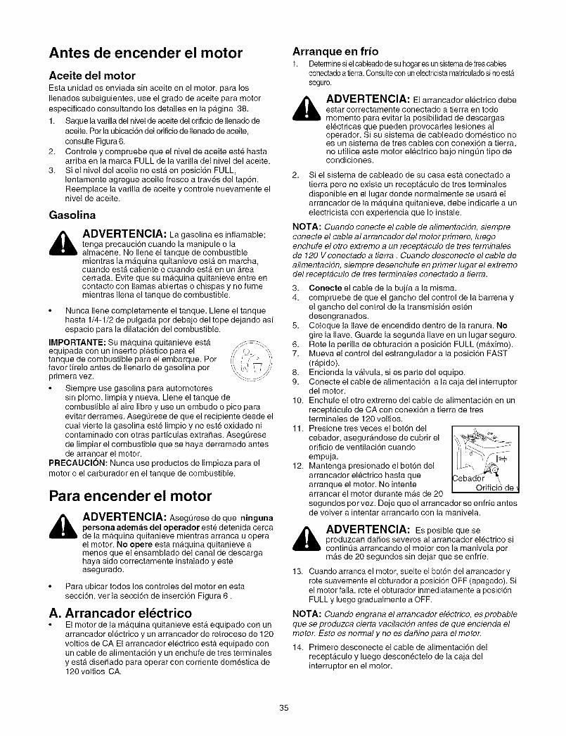
Antes de encender el motor
Aceite del motorEsta unidad es enviada sin aceite en el motor, para losIlenados subsiguientes, use el grado de aceite para motorespecificado consultando los detalles en la pagina 38.
1. Saque lavarilla del nivel de aceite del orificiode Ilenadodeaceite. Por la ubicaci6n del orificio de Ilenado de aceite,consulte Figura 6.
2. Controle y compruebe que el nivel de aceite este hastaarriba en la marca FULL de la varilla del nivel del aceite.
3. Si el nivel del aceite no esta en posici6n FULL,lentamente agregue aceite fresco a traves del tap6n.Reemplace la varilla de aceite y controle nuevamente elnivel de aceite.
Gasolina
_ DVERTENCIA: La gasolina es inflamable;tenga precauci6n cuando la manipule o laalmacene. No Ilene el tanque de combustiblemientras la maquina quitanieve esta en marcha,cuando esta caliente o cuando esta en un Areacerrada. Evite que su maquina quitanieve entre encontacto con llamas abiertas o chispas y no fumemientras Ilena el tanque de combustible.
Arranque en frio1. Determinesiel cableadodesu hogaresunsistemadetrescables
conectadoatierra.ConsulteconunelectricistamatriculadosinoestA
seguro.
_ DVERTENClA: El arrancador el6ctrico debeestar correctamente conectaclo a tierra en todomomento para evitar la posibilidad de descargasel6ctricas que pueden provocarles lesiones aloperador. Si su sistema de cableado domestico noes un sistema de tres cables con conexi6n a tierra,no utilice este motor electrico bajo ningQn tipo decondiciones.
2. Si el sistema de cableado de su casa esta conectado atierra pero no existe un receptaculo de tres terminalesdisponible en el lugar donde normalmente se usara elarrancador de la maquina quitanieve, debe indicarle a unelectricista con experiencia que Io instale.
NOTA: Cuando conecte el cable de alimentacidn, siempreconecte el cable al arrancador del motor primero, luegoenchufe el otro extremo a un receptaculo de tres terminalesde 120 V conectado a tierra . Cuando desconecte el cable dealimentacidn, siempre desenchufe en primer lugar el extremodel receptaculo de tres terminales conectado a tierra.
3.
4.
• Nunca Ilene completamente el tanque. Llene el tanquehasta 1/4-1/2 de pulgada por debajo del tope dejando asfespacio para la dilatacion del combustible. 5.
IMPORTANTE: Su maquina quitanieve esta 6.equipada con un inserto plastico para el 7.tanque de combustible para el embarque. Por
favor tffelo antes de Ilenarlo de gasolina por 8.primera vez. 9.• Siempre use gasolina para automotores
sin plomo, limpia y nueva. Llene el tanque de 10.combustible al aire libre y use un embudo o pico paraevitar derrames. AsegQrese de que el recipiente desde elcual vierte la gasolina este limpio y no este oxidado ni 11.contaminado con otras partfculas extraSas. AsegQresede limpiar el combustible que se haya derramado antesde arrancar el motor.
PRECAUClON: Nunca use productos de limpieza para el 12.motor o el carburador en el tanque de combustible.
Para encender el motor
ADVERTENCIA: AsegQrese de que ningunapersona ademas del operador este detenida cercade la maquina quitanieve mientras arranca u operael motor. No opere esta maquina quitanieve amenos que el ensamblado del canal de descargahaya sido correctamente instalado y esteasegurado.
• Para ubicar todos los controles del motor en estasecci6n, ver la secci6n de inserci6n Figura 6.
A. Arrancador el6ctrico• El motor de la maquina quitanieve esta equipado con un
arrancador el6ctrico y un arrancador de retroceso de 120voltios de CA El arrancador electrico esta equipado conun cable de alimentaci6n y un enchufe de tres terminalesy esta disehado para operar con corriente domestica de120 voltios CA.
Conecte el cable de la bujfa a la misma.compruebe de que el gancho del control de la barrena yel gancho del control de la transmisi6n estendesengranados.Coloque la Ilave de encendido dentro de la ranura. Nogire la Ilave. Guarde la segunda Ilave en un lugar seguro.Rote la perilla de obturacion a posicion FULL (maximo).Mueva el control del estrangulador a la posicion FAST(rapido).Encienda la vMvula, si es parte del equipo.Conecte el cable de alimentaci6n a la caja del interruptordel motor.Enchufe el otro extremo del cable de alimentacion en unreceptaculo de CA con conexion a tierra de tresterminales de 120 voltios.Presione tres veces el boton delcebador, asegurandose de cubrir elorificio de ventilacion cuandoempuja.Mantenga presionado el boton delarrancador el6ctrico hasta quearranque el motor. No intentearrancar el motor durante mas de 20segundos por vez. Deje que el arrancador se enfrfe antesde volver a intentar arrancarlo con la manivela.
_ ADVERTENCIA: Es posible que seproduzcan daSos severos al arrancador el6ctrico sicontinQa arrancando el motor con la manivela pormas de 20 segundos sin dejar que se enfrfe.
13. Cuando arranca el motor, suelte el bot6n del arrancador yrote suavemente el obturador a posici6n OFF (apagado). Siel motor falla, rote el obturador inmediatamente a posici6nFULL y luego gradualmente a OFF.
NOTA: Cuando engrana el arrancador electrico, es probableque se produzca cierta vacilacidn antes de que encienda elmotor. Esto es normal y no es da#ino para el motor.
14. Primero desconecte el cable de alimentaci6n delreceptaculo y luego descon6ctelo de la caja delinterruptor en el motor.
35
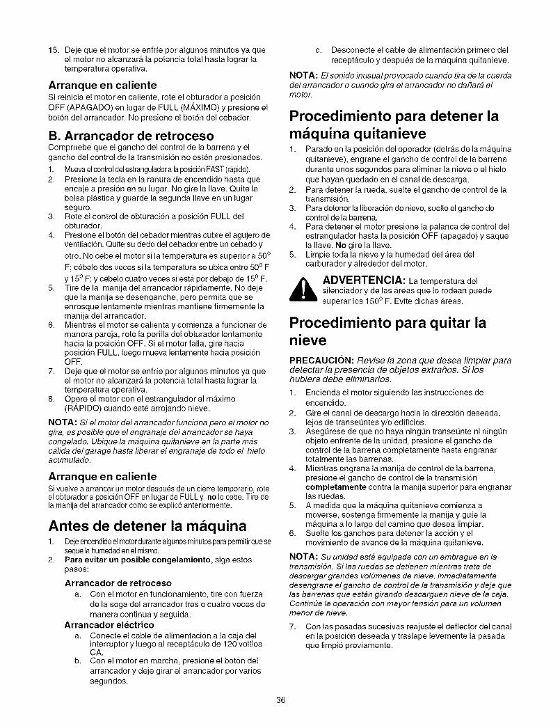
15.DejequeelmotorseenfrfeporalgunosminutosyaqueelmotornoalcanzaralapotenciatotalhastaIograrlatemperaturaoperativa.
Arranque en calienteSi reinicia el motor en caliente, rote el obturador a posici6nOFF (APAGADO) en lugar de FULL (M_,XIMO) y presione elboton del arrancador. No presione el bot6n del cebador.
B. Arrancador de retrocesoCompruebe que el gancho del control de la barrena y elgancho del control de la transmisi6n no esten presionados.
1. Muevaelcontroldelestranguladoralaposici6nFAST(rapido).2. Presione la tecla en la ranura de encendido hasta que
encaje a presi6n en su lugar. No gire la Ilave. Quite labolsa plAstica y guarde la segunda Ilave en un lugarseguro.
3. Rote el control de obturaci6n a posiciSn FULL delobturador.
4. Presione el botSn del cebador mientras cubre el agujero deventilaci6n. Quite su dedo del cebador entre un cebado y
otro. No cebe el motor si la temperatura es superior a 500
F; cebelo dos veces si la temperatura se ubica entre 50° F
y 15° F; y cebelo cuatro veces siestA pot debajo de 150 F.5. Tire de la manija del arrancador rApidamente. No deje
que la manija se desenganche, pero permita que seenrosque lentamente mientras mantiene firmemente lamanija del arrancador.
6. Mientras el motor se calienta y comienza a funcionar demanera pareja, rote la perilla del obturador lentamentehacia la posici6n OFF. Si el motor falla, gire haciaposiciSn FULL, luego mueva lentamente hacia posici6nOFF.
7. Deje que el motor se enfrfe por algunos minutos ya queel motor no alcanzarA la potencia total hasta Iograr latemperatura operativa.
8. Opere el motor con el estrangulador al maximo(R_,PIDO) cuando este arrojando nieve.
NOTA: Si el motor del arrancador funciona pero el motor nogira, es posible que el engranaje del arrancador se hayacongelado. Ubique la maquina quitanieve en la parte mascalida del garage hasta liberar el engranaje de todo el hieloacumulado.
Arranque en calienteSi vuelve a arrancar un motor despues de uncierre temporario, roteel obturador a posici6n OFF en lugar deFULL y no Io cebe. Tire dela manija del arrancador como se explic6 anteriormente.
Antes de detener la m quina1. Dejeencendidoelmotordurantealgunosminutosparapermitirquese
sequela humedadenelmismo.2. Para evitar un posible congelamiento, siga estos
pasos:
Arrancador de retroceso
a. Con el motor en funcionamiento, tire con fuerzade la soga del arrancador tres o cuatro veces demanera continua y seguida.
Arrancador el_ctrico
a. Conecte el cable de alimentaci6n a la caja delinterruptor y luego al recepta.culo de 120 voltiosCA.
b. Con el motor en marcha, presione el botSn delarrancador y deje girar el arrancador por variossegundos.
c. Desconecte el cable de alimentaci6n primero delreceptaculo y despues de la maquina quitanieve.
NOTA: El sonido inusual provocado cuando tira de la cuerdadel arrancador o cuando gira el arrancador no da#ara elmotor.
Procedimiento para detener lam quina quitanieve1. Parado en la posici6n del operador (detras de la maquina
quitanieve), engrane el gancho de control de la barrenadurante unos segundos para eliminar la nieve o el hieloque hayan quedado en el canal de descarga.
2. Para detener la rueda, suelte el gancho de control de latransmisi6n.
3. Para detener la liberacion de nieve, suelte el gancho decontrol de la barrena.
4. Para detener el motor presione la palanca de control delestrangulador hasta la posicion OFF (apagado) y saquela Ilave. No gire la Ilave.
5. Limpie toda la nieve y la humedad del Area delcarburador y alrededor del motor.
_ ADVERTENCIA: La temperatura delsilenciador y de las Areas que Io rodean puedesuperar los 150 ° F. Evite dichas Areas.
Procedimiento para quitar lanievePRECAUCION: Revise la zona que desea limpiar paradetectar la presencia de objetos extra#os. Si loshubiera debe eliminarlos.
1. Encienda el motor siguiendo las instrucciones deencendido.
2. Gire el canal de descarga hacia la direcci6n deseada,lejos de transet_ntes y/o edificios.
3. Asegt_rese de que no haya ningQn transet_nte ni ningunobjeto enfrente de la unidad, presione el gancho decontrol de la barrena completamente hasta engranartotalmente las barrenas.
4. Mientras engrana la manija de control de la barrena,presione el gancho de control de la transmisi6ncompletamente contra la manija superior para engranarlas ruedas.
5. A medida que la maquina quitanieve comienza amoverse, sostenga firmemente la manija y gufe lamaquina a Io largo del camino que desea limpiar.
6. Suelte los ganchos para detener la acci6n y elmovimiento de avarice de la maquina quitanieve.
NOTA: Su unidad esta equipada con un embrague en latransmisiSn. Si las ruedas se detienen mientras trata de
descargar grandes volbmenes de nieve, inmediatamentedesengrane el gancho de control de la transmisi6n y deje quelas barrenas que est_n girando descarguen nieve de la caja.Continbe la operaciSn con mayortensi6n para un volumenmenor de nieve.
7. Con las pasadas sucesivas reajuste el deflector del canalen la posicion deseada y traslape levemente la pasadaque limpi6 previamente.
36
Consejos de operacibnNOTA: Deje que el motor se caliente unos minutos ya que elmismo no desarrolla la potencia maxima hasta que alcanza latemperatura de funcionamiento.
• Para que el quitado de la nieve sea mas eficiente debehacerlo inmediatamente despues de la cafda de lamisma.
• En Io posible, descargue la nieve en direccion al viento.Traslape levemente las pasadas anteriores.
• Configure las zapatas antideslizantes 1/4" por debajo dela barra de raspado para un uso normal. Las zapatasantideslizantes se pueden ajustar hacia arriba cuando lanieve este muy compactada.
NOTA: No se recomienda que opere esta maquinaquitanieve sobre gravas, ya que es posible que la maquinaquitanieve tome las gravas sueltas y la barrena las expulse, Iocual podrfa causar lesiones personales y/o da#ar la maquinaquitanieve.
• Si por algOn motivo tiene que usar la maquina quitanievesobre grava, mantenga la zapata antideslizante en laposicion ma.s elevada para Iograr una separacidnmaxima entre el suelo y la placa de raspado.
• Limpie cuidadosamente la maquina quitanieve despuesde cada uso.
Herramienta de limpieza del canal
_L DVERTENCIA: Detenga el motor quitandola Ilave de encendido y espere que se detenganTODAS las partes moviles antes de usar laherramienta de limpieza del canal.
La herramienta de limpieza esta ajustada convenientementea la parte posterior de la caja de la barrena con una horquillade ensamblado. Ver 6. Vuelva a colocar la Ilave de encendido
y arranque el motor de la maquina quitanieve para continuarquitando nieve..
Cuando se acumulen nieve y hielo en el canal de descargadurante la operacion, use esta herramienta para limpiar demanera segura el canal y la abertura del canal. Siga lospasos que aparecen debajo para operarla:1. Sueltelosganchosdecontrolde labarrenay latransmisi6n.2. Para detener el motor saque la Ilave de encendido.3. Saque la herramienta de limpieza de la horquilla que la
ajusta a la parte posterior de la caja de la barrena.4. Use el extremo con forma de pala de la herramienta de
limpieza para desplazar y recoger la nieve y el hielo que seformaron cerca del canal de descarga.
_ ADVERTENCIA: Nunca use sus manos paralimpiar la nieve y el hielo del canal de descarga o lacaja de la barrena.
5. Vuelva a ajustar la herramienta de limpieza del canal a lahorquilla de ensamblado ubicado en la parte posterior de lacaja de la barrena.
6. Vuelva a colocar la Ilave deencendido y arranque el motor dela maquina quitanieve para continuar quitando nieve.
37
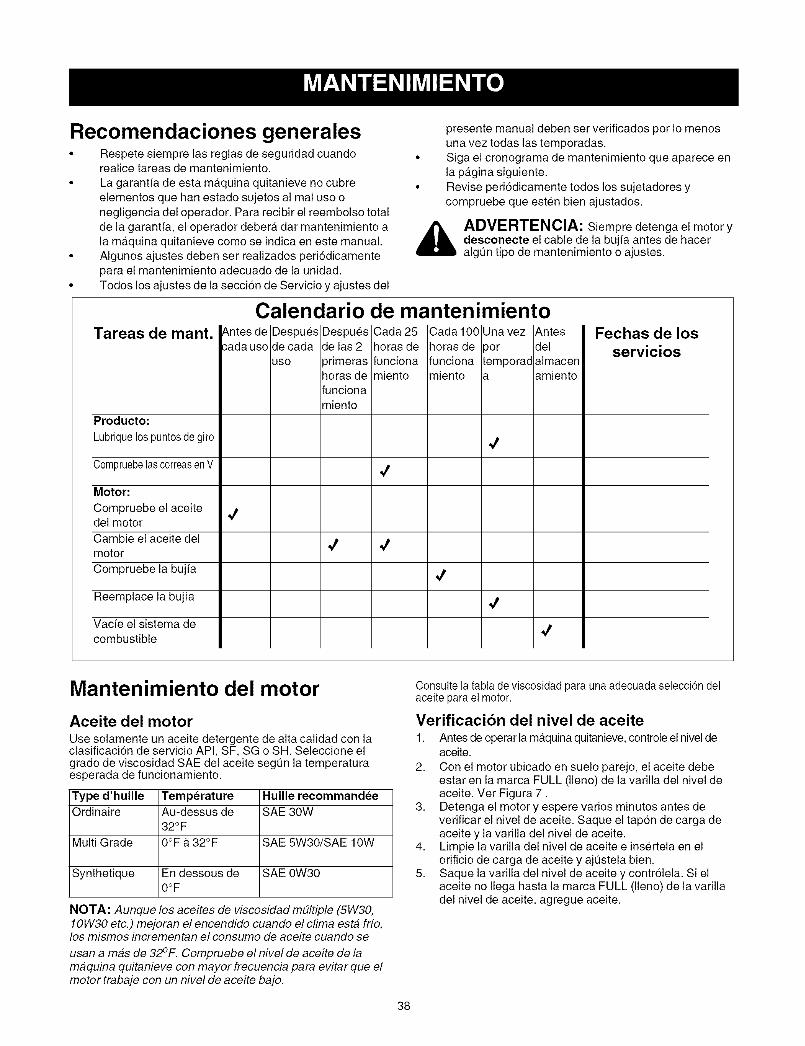
Recomendaciones generales• Respete siempre las reglas de seguridad cuando
realice tareas de mantenimiento.
• La garantfa de esta maquina quitanieve no cubreelementos que hart estado sujetos al real use onegligencia del operador. Para recibir el reembolso totalde la garant[a, el operador debera, dar mantenimiento ala ma.quina quitanieve come se indica en este manual.
• Algunos ajustes deben ser realizados peri6dicamentepara el mantenimiento adecuado de la unidad.
• Todos los ajustes de la secci6n de Servicio y ajustes del
Tareas de mant.
Producto:
Lubriquelospuntosdegiro
CompruebelascorreasenV
Motor:
Compruebe el aceitedel motor
Cambie el aceite delmotor
Compruebe la bujia
Reemplace la bujfa
Vacie el sistema decombustible
4
presente manual deben set verificados per Io menosuna vez todas las temporadas.
• Siga el cronograma de mantenimiento que aparece enla pagina siguiente.
• Revise peri6dicamente todos los sujetadores ycompruebe que esten bien ajustados.
_ DVERTENCIA: Siempre detenga el motor ydesconecte el cable de la bujia antes de haceralgt]n tipo de mantenimiento o ajustes.
Calendario de mantenimientoCada 25horas defuncionamiento
¢
4
Cada 100horas defuncionamiento
4
4
Fechas de losservicios
Mantenimiento del motor
Aceite del motorUse solamente un aceite detergente de alta calidad con laclasificaci6n de servicio API, SF, SG o SH. Seleccione elgrade de viscosidad SAE del aceite segt]n la temperaturaesperada de funcionamiento.
Type d'huille TemperatureOrdinaire Au-dessus de
32OF
Multi Grade 0°F & 32°F
Synthetique En dessous de0OF
NOTA: Aunque los aceites de viscesidad m#ltiple (5W30,10W30 etc.) mejoran el encendide cuando el clima esta fife,los mismos incrementan el consume de aceite cuando se
usan a mas de 32°F. Cempruebe el nivel de aceite de lamaquina quitanieve con mayor frecuencia para evitar que elmotortrabaje con un nivel de aceite bajo.
Huille recommandee
SAE 30W
SAE 5W30/SAE 10W
SAE 0W30
Consulte latabla de viscosidad para una adecuada selecci6n delaceite para el motor.
Verificacibn del nivel de aceite1. Antes de operar la maquina quitanieve, controle el nivel de
aceite.
2. Con el motor ubicado en suelo parejo, el aceite debeestar en la marca FULL (lleno) de la varilla del nivel deaceite. Ver Figura 7.
3. Detenga el motor y espere varies minutes antes deverificar el nivel de aceite. Saque el tapon de carga deaceite y la varilla del nivel de aceite.
4. Limpie la varilla del nivel de aceite e insertela en elorificio de carga de aceite y ajt]stela bien.
5. Saque la varilla del nivel de aceite y contr61ela. Si elaceite no Ilega hasta la marca FULL (lleno) de la varilladel nivel de aceite, agregue aceite.
38

A Varilla del nivel del aceite
Rellene si
se/requiere
aceite
/cFigura 7
Cambio de aceiteCambio de aceite del motor despues de las dos primerashoras de operacion y a partir de ah/cada 25 horas deoperaci6n.Para realizar el cambio de aceite primero debe vaciar elmotor del aceite usado y luego volver a Ilenarlo con aceitenuevo.
1. Drene el aceite mientras el motor esta caliente. Saque latapa de drenado del aceite ubicada en la base delarrancador de retroceso del motor. Junte el aceite en unrecipiente adecuado.
2. Cuando se haya vaciado todo el motor de aceite, vuelvaa colocar el tap6n de drenado bien ajustado.
3. Saque la varilla del nivel de aceite del orificio de Ilenadode aceite. Por la ubicaci6n del orificio de Ilenado deaceite, consulte Figura 6. Vierta aceite nuevo lentamentea traves del tapon. Reemplace la varilla del nivel deaceite.
4. Controle y compruebe que el nivel de aceite este hastaarriba en la marca FULL de la varilla del nivel del aceite.
Bujia de encendidoLimpie la bujfa y ajuste el espacio de electrodos a 0.030" almenos una vez por estaci6n o cada 100 horas defuncionamiento; reemplacela cada 200 horas de operacion.• Limpie el area alrededor de la base de la bujfa.• Saque e inspeccione la bujfa.• Cambie la bujfa si los electrodos estan picados,
quemados o la porcelana esta rota. Vet Figura 8.
NOTA: No lije la bujfa. Se deben limpiar las bujfas medianteraspado o tallado con cepillo de alambre y lavado con unsolvente comercial.
Electrodos
.030" PorcelanaDistancia
Figura 8
Lubricaci6nPara ubicar los puntos de lubricacidn de la maquinaquitanieve, consulte Figura 9.1. Unavez portemporada,hbriquelospuntosdegiroenelganchodel
controlde labarrenaconunaceitelivianoparamotor.2. Una vez pot temporada, lubrique el soporte intermedio
de la barrena con un aceite liviano.
Lubrique aquf.
lue aqul.
Figura 9
Compruebe las correas en VSiga las instrucciones a continuaci6n para verificar elestado de las correas de transmisidn cada 50 horas defuncionamiento.
1. Saque la cubierta plastica de la correa ubicada en elfrente del motor. Para ello saque los tornilloautoroscante.
2. Compruebe visualmente la existencia de correas rafdas,agrietadas o excesivamente gastadas. En caso de sernecesario, reemplacelo segt]n las instrucciones de lapagina 40.
39

_ DVERTENClA: Detenga siempre el motorde la maquina quitanieve, desconecte el cable de labujfa y p6ngalo separado de la misma antes derealizar todo tipo de ajustes o reparaciones.
ADVERTENClA: Nunca intente limpiar elcanal o realizar ajustes mientras el motor esta enfuncionamiento.
Placa de raspado y zapatasantideslizantesLa placa de raspado y las zapatas antideslizantes ubicadasen la base de la maquina quitanieve estan sujetas adesgaste. Periodicamente deberfa controlar los pernos yreemplazarlos cuando sea necesario.1. Saque los cuatro pernos de carro, las arandelas belleville y las
tuercas hexagonales que ajustan las zapatas antideslizantes alos dos costados de la maquina quitanieve. Ver Figura 10.
2. Vuelva a montar las zapatas antideslizantes nuevos concuatros tornillos de carro, arandelas belleville (el ladoconico va contra las zapatas antideslizantes) y lastuercas hexagonales. Compruebe que las zapatasantideslizantes esta.n ajustadas para que quedenparejas.
3. Para sacar la placa de raspado, saque la zapata y elresto de las piezas metalicas, incluyendo los pernos decarro, las arandelas belleville y las tuercas hexagonalesque ajustan la placa de raspado a la caja de la maquinaquitanieve. Por la ubicaci6n de la placa de raspado,consulte Figura 10.
4. Vuelva a ensamblar la placa de raspado nueva,asegurandose de que las tapas de los pernos de carro seencuentren del lado interior de la caja. Vuelva a instalarla zapata antideslizante AjQstela bien.
Perno de cuchilla
\\\Tuerca de seguridad hexagonal\
\
Pernodel carro
Perno_
Ra_pado_del carro j• ._,. uercaTuerca
Placa Anhdeshzante HexagonalZapata
Figura 10
BarrenasLas barrenas estan ajustadas al eje espiral con dospernos de cuchilla y tuercas hexagonales deseguridad. Ver Figura 10. Si golpea un objeto extraSoo una barra de hielo, la mb.quina quitanieve esta
diseSada de manera que los pernos se cortan.Si las barrenas no giran, verifique si los pernos se cortaron.Reemplacelos cuando sea necesario. Ver Figura 10.
Junto con la maquina quitanieve se incluyen dos pernos decuchilla y tuercas hexagonales de seguridad de repuesto.Este tipo de tuercas se utiliza cuando hay alguna vibraci6n.Use una Ilave allen ya que las tuercas de seguridad no sepueden enroscar a los pernos de forma manual• Cuandoreemplace los pernos, rocfe un lubricante de aceite dentro deleje antes de colocar los pernos nuevos.
Reemplazo de las correasNOTA: Esta maquina quitanieve viene equipada con doscorreas: correa de la barrena y correa de transmisidn: Serecomienda que ambas correas sean reemplazadas al mismotiempo.
1. Desconecte el cable de la bujfa y pongalo de manera quehaga masa contra el motor•
2. Drene la gasolina del tanque de combustible o coloqueun trozo de plastico debajo del tapon de Ilenado delcombustible para evitar una perdida de gasolina.
3. Quite el tornillo demostrado en el cuadro 12, y empuje la
cubierta de la correa para lanzar las leng(Jetas plasticas.Empuje la cubierta de la correa de alrededor del motor yel canal• Saquela y guardela. Ver Figura 11.
Cubierta de la correa/
Figura 11
Correas de las barrenas1. Deslice la correa frontal de la barrena hasta sacarla de la polea
del motor presionandola entre el soporte intermedio y la poleadel motor• Ver Figura 12.
2. Apriete el gancho del control de la barrena para liberar latensi6n en la correa de la barrena; quite la correa.
3. Reemplacela por la nueva correa despuee dereemplazar la correa de transmisi6n. Siga lainstrucciones de la pagina siguiente para reemplazar lacorrea de transmision.
40

Figura 12
Correa de transmisibn
intermedio
NOTA: Reemplace la cerrea de transmisidn antes de velvera ensamblarla nueva cerrea de la barrena.
1. Incline la maquina quitanieve hacia arriba y hacia adelante demanera que quede apoyada sobre la caja.
2. Quite el resorte que conecta la transmision a un perno enel cuadro del motor. Ver Figura 13.
Resorte
Polea detransmision
Polea_e la barrena
\\
Correa detransmision
NOTA: Se exhibe la transmision empujada haciaadelante.
Figura 13
3. Gire la transmision hacia adelante para soltar la presi6nen la correa de transmision.
4. Quite la correa de transmision de alrededor de la poleadel motor y alejela de la unidad.
5. Ubique una nueva correa de transmisi6n dentro de laranura de la polea del motor. Vet Figura 13.
6. Incline la transmision hacia adelante y ubique la correade transmision en la polea de transmisi6n.
7. Vuelva a conectar el resorte al perno en el marco delmotor y ajuste la transmision.
8. Vuelva a montar la cubierta de la correa en la maquinaquitanieve:
Ajustes
Cable de la barrenaEs posible que se requieran ajustes periodicos del cable de controlde la barrena debido al estiramiento y al desgaste normal de lacorrea. Se necesitaran ajustes si las barrenas parecen temblarmientras giran, pero el motor mantiene su velocidad.
1. Quite la cubierta de la correa presionando las aletas que laajusta a la caja de la maquina quitanieve. Empuje la cubiertade la correa de alrededor del motor y el canal y alejela de lamaquina. Ahora puede acceder al cable de la barrena.
2. Ajuste dos tuercas hexagonales en el cable de la barrenahacia el resorte para aumentar la tension de la correa dela barrena. Ver Figura 14.
3. Vuelva a ensamblar la cubierta de la correa.
Cubierta de
hexagonal
_-- Tornillo
Cable de la barrena
Figura 14
Zapata antideslizante
Refiera a la pagina 6 de este manual.
41

Sinoseutilizaraelequipodurante30dfasomas,oalfinalizarlatemporadadenievecuandoyanoexisteposibilidaddequenieve,esnecesarioalmacenarelequipodemaneraadecuada.Sigalasinstruccionesdealmacenamientoqueseindicanacontinuaci6nparagarantizarelrendimientomaximodelamaquinaquitanievedurantemuchosaSosmas.
Preparacibn del motor
ADVERTENCIA: Nunca almacene la maquina
quitanieve, cuando at]n tiene combustible en eltanque, en un espacio cerrado o en Areas con pocaventilacidn donde los gases del combustible puedanalcanzar el fuego, chispas o una luz piloto como laque tienen algunos hornos, calentadores de agua,secadores de ropa o algt]n otro dispositivo a gas.
NOTA: Es importante evitar que durante el almacenamientose formen depdsitos de goma en las piezas esenciales delsistema de combustible del motor como, por ejemplo, en elcarburador, el filtro de combustible, la manguera decombustible o el depdsito.
ADVERTENCIA: La experiencia indica tambien que los
combustibles con mezcla de alcohol (que se Ilaman gasohol oque utilizan etanol o metanol) pueden atraer la humedad, lacual conduce a la separacion y formaci6n de acidos duranteel almacenamiento. El gas acfdico puede daSar el sistema delcombustible de un motor durante el almacenamiento delmismo.
Para evitar problemas con el motor, el sistema delcombustibledebe ser vaciadoantes de almacenar la maquinadurante 30 d[as o mas. Siga estas instrucciones parapreparar su maquina quitanieve para almacenarla:
_ ADVERTENCIA: Drene el combustible dentrode un recipiente aprobado en un lugar exterior, lejosde todo tipo de fuego. Compruebe que el motor estefifo. No fume. El combustible que se deje en elmotor se deteriora cuando el clima es calido y causagraves problemas de encendido.
1. Saque toda la gasolina del carburador y del dep6sito decombustible para evitar la formacion de depositos degoma dentro de los mismos que pueden dahar el motor.
Carburado__
Drenaje_ _:::_de la taza
Figura 15
2. Ponga el motor en marcha hasta vaciar el dep6sito decombustible y hasta que el motor se detenga debido a lafalta de combustible.
3. Drene el carburador presionando hacia arriba el drenajede la taza, ubicado debajo de la cubierta del carburador.Ver Figura 15.
_ ADVERTENCIA: No drene el carburador siesta utilizando un estabilizador de combustible. Enel dep6sito de combustible no use nunca productosde limpieza para motores o carburadores o podrfaproducir daSos permanentes.
NOTA: El uso de estabilizadores de combustible (comoSTA-BIL) es una altemativa aceptable para minimizar laformacidn de depdsitos de goma de combustible durante elalmacenamiento. Agregue el estabilizador a la gasolina quese encuentra en el depdsito de combustible o en el recipientede almacenamiento. Respete siempre la proporcidn demezclado que figura en el recipiente del estabilizador. Pongael motor en marcha por Io menos 10 minutos despu#s deagregar el estabilizador para permitirle flegar al carburador.No drene el carburador siesta utilizando un estabilizador decombustible.
4, Retire la bujfa y vierta (1) onza de aceite para motor atraves del orificio de la bujia y hacia el interior del cilindro.Cubra el orificio de la bujfa con un trapo y ponga el motoren marcha varias veces para distribuir el aceite.Reemplace la bujfa.
Preparacibn de la m quinaquitanieve1. Cuando almacene la maquina quitanieve en un galpon
de deposito metalico o con poca ventilacion, tengaespecial cuidado de realizarle un tratamiento anti-oxidante al equipo. Use aceite ligero o silicon pararecubrir el equipo, especialmente las cadenas, losresortes, los cojinetes y los cables.
2. Elimine todo el polvo del exterior del motor y del equipo.3. Siga las recomendaciones de lubricaci6n en la pagina 41.4. Almacenela en un Area despejada y seca.
42

Problema Causa posible Solucibn
El motor no arranca 1. Eltanquedecombustibleestavacioo elcombustibleesviejo2. La Ifnea del combustible esta bloqueada3. La obturaci6n no esta en posicion ON
(ENCENDIDO)4. La bujfa no funciona correctamente5. La Ilave no esta. en el interruptor de encendido
6,
7.
Se ha desconectado el cable de la bujfa
El motorfuncionade 1.manera erratica
2.
3.
El motor pierde 1.potencia 2.
Demasiada 1.vibraci6n
La unidad no se 1.autopropulsa
2.
La unidad no 1.descarga la nieve
2.3.
4.
5,
El cebador no fue utilizado correctamente.
Launidadestafuncionandoenposiciondeobturaci6nFULL.La Ifnea del combustible esta tapada o lagasolina es vieja.Agua o suciedad en el sistema del combustible
Elcablede labujfaestaflojoEl orificio de ventilacion del tapon de Ilenado delcombustible esta. obstruido.
Hay piezas que estan flojas o la barrena estadaSada
Elcabledecontrolde transmisi6nnoestaajustado
La correa de transmisidn esta floja o daSada
Elcanaldedescargaestatapado
Los pernos de cuchilla se cortaron.Hay un objeto extraho en la barrena
El cable del control de la barrena necesita unajuste.La correa de la barrena esta floja o dahada.
1. Lleneeltanquecongasolinalimpia.2. Limpie la Ifnea del combustible.3. Rote la palanca de obturaci6n a posici6n
ON (ENCENDIDO).4. Limpie, ajuste o reemplace la bujfa.5. Inserte la Ilave totalmente dentro del
interruptor; no la gire.6. Conecte el cable de la bujfa a la bujfa del
motor.7. Cebe el motor tal como se explic6
anteriormente. Si el carburador estaahogado debido a un cebado excesivo,espere hasta que este seco.
1. Rotelaperilladeobturaciona posici6nOFF(APAGADO).
2. Limpie la Ifnea del combustible; Ilene eltanque con gasolina limpia.
3. Drene el dep6sito de combustible y elcarburador. Llenelos con gasolina limpia.
1. Conecteelcablede labujfa.2. Retire el hielo y la nieve del tapon de
Ilenado del combustible. Compruebe queel orificio de ventilaci6n no este obstruido.
Detenga el motor de inmediato ydesconecte el cable de la bujia. Ajustetodos los pernos y las tuercas. Si lavibraci6n contint]a, comunfquese con elcentro de servicio de Sears.
1. Ajuste el cable de control de transmisionsiguiendo las instrucciones detalladasanteriormente.
2. Reemplace la correa de transmision.
1. Detengael motory desconecteel cabledela bujia.Limpieel canaldedescargayel interiordelacajadelabarrena.
2. Reemplace el perno de cuchilla.3. Detenga el motor de inmediatoy
desconecte el cable de la bujfa. Retire elobjeto de la barrena.
4. Ajuste el cable del control de la barrena.
5. Reemplace la correa de la barrena.
NOTA: En esta seccidn se analizan problemas menores de servicio. Si desea mas informacidn comunfquese con el servicio deSears al 1-800-4-MY-HOME®.
43

Your HomeFor repair-in your home-of all major brand appliances,
lawn and garden equipment, or heating and cooling systems,
no matter who made it, no matter who sold it! ..................
For the replacement parts, accessories and
owner's manuals that you need to do-it-yourself. ....................................
For Sears professional installation of home appliances
and items like garage door openers and water heaters. ..................
1-8 00-4-MY-H 0 ME® (1-800-469-4663)
oa,,an t, o, o,oht sodOaoada ..................www.sears.com www.sears.ca
OurHomeFor repair of carry-in items like vacuums, lawn equipment,
and electronics, call or go on-line for the location of your nearest
Sears Parts & Repair Center.
1-800-488-1222Call anytime, day or night (U.S.A. only)
www.sears.com
To purchase a protection agreement (U.S.A.)
or maintenance agreement (Canada) on a product serviced by Sears:
1-800-827-6655 (U.S.A.) 1-800-361-6665 (Canada)
Pard pedir servicio de reparacien Au Canada pour service en frangais:
a domicilio, y para ordenar piezas. 1-800- LE- FOYER Mc1-8 88-S U- HOGAR sM
(1-800-533-6937)
(1-888-784-6427) www.sears.ca .............................
SEARSSM® Registered Trademark / TMTrademark / Service Mark of Sears, Roebuck and Co.
TM SM® Marca Registrada / Marca de F_brica / Marca de Servicio de Sears, Roebuck and Co.MC MDMarque de commerce / Marque d6pos6e de Sears, Roebuck and Co. ® Sears, Roebuck and Co.