oxford atpl 4th ed book 03_aircraft general knowledge 2_electrics
DESCRIPTION
Oxford ATPL 4th Ed Book 03_Aircraft General Knowledge 2_ElectricsTRANSCRIPT


ii
Introduction AIRCRAFT GENERAL KNOWLEDGEELECTRICS and ELECTRONICS
© Oxford Aviation Academy (UK) Limited 2008All Rights Reserved
This text book is to be used only for the purpose of private study by individuals and may not be reproduced in any form or medium, copied, stored in a retrieval system, lent, hired, rented, transmitted or adapted in whole or in part without the prior written consent of Oxford Aviation Academy.
Copyright in all documents and materials bound within these covers or attached hereto, excluding that material which is reproduced by the kind permission of third parties and acknowledged as such, belongs exclusively to Oxford Aviation Academy.
Certain copyright material is reproduced with the permission of the International Civil Aviation Organisation, the United Kingdom Civil Aviation Authority and the European Aviation Safety Agency (EASA).
This text book has been written and published as a reference work to assist students enrolled on an approved EASA Air Transport Pilot Licence (ATPL) course to prepare themselves for the EASA ATPL theoretical knowledge examinations. Nothing in the content of this book is to be interpreted as constituting instruction or advice relating to practical flying.
Whilst every effort has been made to ensure the accuracy of the information contained within this book, neither Oxford Aviation Academy nor the distributor gives any warranty as to its accuracy or otherwise. Students preparing for the EASA ATPL theoretical knowledge examinations should not regard this book as a substitute for the EASA ATPL theoretical knowledge training syllabus published in the current edition of ‘CS-FCL 1 Flight Crew Licensing (Aeroplanes)’ (the Syllabus). The Syllabus constitutes the sole authoritative definition of the subject matter to be studied in an EASA ATPL theoretical knowledge training programme. No student should prepare for, or is currently entitled to enter himself/herself for the EASA ATPL theoretical knowledge examinations without first being enrolled in a training school which has been granted approval by an EASA authorised national aviation authority to deliver EASA ATPL training.
Oxford Aviation Academy excludes all liability for any loss or damage incurred or suffered as a result of any reliance on all or part of this book except for any liability for death or personal injury resulting from Oxford Aviation Academy’s negligence or any other liability which may not legally be excluded.
Cover Photograph: Airbus A320 cockpit - overhead panel
Photographed by Ismael Jorda, for www.airteamimages.com
This edition distributed by Transair (UK) Ltd, Shoreham, England: 2008Printed in Singapore by KHL Printing Co. Pte Ltd

iii
IntroductionAIRCRAFT GENERAL KNOWLEDGEELECTRICS and ELECTRONICS
Textbook Series
Book Title EASA Ref. No. Subject
1 010 Air Law 010
2 020 Aircraft General Knowledge 1 021 01 Airframes & Systems
021 01 01-04 Fuselage, Wings & Stabilising Surfaces021 01 05 Landing Gear021 01 06 Flight Controls021 01 07 Hydraulics021 01 08-09 Air Systems & Air Conditioning021 01 10 Anti-icing & De-icing021 01 11 Fuel Systems021 04 00 Emergency Equipment
3 020 Aircraft General Knowledge 2 021 02 Electrics – Electronics
021 02 01 Direct Current021 02 02 Alternating Current021 02 05 Basic Radio Propagation.
4 020 Aircraft General Knowledge 3 021 00 Powerplant
021 03 01 Piston Engines021 03 02 Gas Turbines
5 020 Aircraft General Knowledge 4 022 Instrumentation
022 01 Flight Instruments022 03 Warning & Recording022 02 Automatic Flight Control022 04 Power Plant & System Monitoring Instruments
6 030 Flight Performance & Planning 1 031 Mass & Balance032 Performance
7 030 Flight Performance & Planning 2 033 Flight Planning & Monitoring
8 040 Human Performance & Limitations 040
9 050 Meteorology 050
10 060 Navigation 1 061 General Navigation
11 060 Navigation 2 062 Radio Navigation
12 070 Operational Procedures 070
13 080 Principles of Flight 080
14 090 Communications 091 VFR Communications092 IFR Communications

iv
Introduction AIRCRAFT GENERAL KNOWLEDGEELECTRICS and ELECTRONICS

v
IntroductionAIRCRAFT GENERAL KNOWLEDGEELECTRICS and ELECTRONICS
Book Contents
DC ELECTRICS
1. BASIC PRINCIPLES . . . . . . . . . . . . . . . . . . . . . . . . . . . . . . . . . . . 1
2. SWITCHES . . . . . . . . . . . . . . . . . . . . . . . . . . . . . . . . . . . . . . . .27
3. CIRCUIT PROTECTION and CAPACITORS . . . . . . . . . . . . . . . . . . . . .35
4. BATTERIES . . . . . . . . . . . . . . . . . . . . . . . . . . . . . . . . . . . . . . . .51
5. MAGNETISM . . . . . . . . . . . . . . . . . . . . . . . . . . . . . . . . . . . . . . .69
6. GENERATORS and ALTERNATORS. . . . . . . . . . . . . . . . . . . . . . . . . .81
7. DC MOTORS . . . . . . . . . . . . . . . . . . . . . . . . . . . . . . . . . . . . . . 105
8. AIRCRAFT ELECTRICAL POWER SYSTEMS . . . . . . . . . . . . . . . . . . . 123
9. BONDING and SCREENING . . . . . . . . . . . . . . . . . . . . . . . . . . . . . 147
10. SPECIMEN QUESTIONS . . . . . . . . . . . . . . . . . . . . . . . . . . . . . . . 153
AC ELECTRICS
11. INTRODUCTION TO AC . . . . . . . . . . . . . . . . . . . . . . . . . . . . . . . 165
12. ALTERNATORS . . . . . . . . . . . . . . . . . . . . . . . . . . . . . . . . . . . . 191
13. PRACTICAL AIRCRAFT SYSTEMS . . . . . . . . . . . . . . . . . . . . . . . . . 225
14. TRANSFORMERS . . . . . . . . . . . . . . . . . . . . . . . . . . . . . . . . . . . 235
15. AC MOTORS . . . . . . . . . . . . . . . . . . . . . . . . . . . . . . . . . . . . . . 245
16. BASIC COMPUTERS . . . . . . . . . . . . . . . . . . . . . . . . . . . . . . . . . . 255
17. SEMICONDUCTORS . . . . . . . . . . . . . . . . . . . . . . . . . . . . . . . . . 273
18. LOGIC GATES . . . . . . . . . . . . . . . . . . . . . . . . . . . . . . . . . . . . . 285
RADIO PROPAGATION
19. PROPERTIES of RADIO WAVES . . . . . . . . . . . . . . . . . . . . . . . . . . . 301
20. RADIO PROPAGATION THEORY . . . . . . . . . . . . . . . . . . . . . . . . . . 315
21. MODULATION . . . . . . . . . . . . . . . . . . . . . . . . . . . . . . . . . . . . . 333
22. ANTENNAE . . . . . . . . . . . . . . . . . . . . . . . . . . . . . . . . . . . . . . 347
23. OSCILATORS . . . . . . . . . . . . . . . . . . . . . . . . . . . . . . . . . . . . . . 359

vi
Introduction AIRCRAFT GENERAL KNOWLEDGEELECTRICS and ELECTRONICS

1
Chapter 1DC ElectricsBasic Principles
CHAPTER ONE
BASIC PRINCIPLES
Contents
INTRODUCTION . . . . . . . . . . . . . . . . . . . . . . . . . . . . . . . . . . . . . . . . 3
ELECTRO MOTIVE FORCE (EMF) . . . . . . . . . . . . . . . . . . . . . . . . . . . . . . 4
CURRENT. . . . . . . . . . . . . . . . . . . . . . . . . . . . . . . . . . . . . . . . . . . . . 5
RESISTANCE . . . . . . . . . . . . . . . . . . . . . . . . . . . . . . . . . . . . . . . . . . . 6
FACTORS AFFECTING THE RESISTANCE . . . . . . . . . . . . . . . . . . . . . . . . . 6
UNITS OF RESISTANCE . . . . . . . . . . . . . . . . . . . . . . . . . . . . . . . . . . . . 6
RESISTORS . . . . . . . . . . . . . . . . . . . . . . . . . . . . . . . . . . . . . . . . . . . . 7
OHMS LAW. . . . . . . . . . . . . . . . . . . . . . . . . . . . . . . . . . . . . . . . . . . . 7
POWER . . . . . . . . . . . . . . . . . . . . . . . . . . . . . . . . . . . . . . . . . . . . . . 7
SERIES AND PARALLEL CIRCUITS . . . . . . . . . . . . . . . . . . . . . . . . . . . . . 8
KIRCHOFF’S LAWS . . . . . . . . . . . . . . . . . . . . . . . . . . . . . . . . . . . . . . 10
WHEATSTONE BRIDGE . . . . . . . . . . . . . . . . . . . . . . . . . . . . . . . . . . . 12
QUESTIONS – THEORY . . . . . . . . . . . . . . . . . . . . . . . . . . . . . . . . . . . 14
QUESTIONS - UNITS 1 . . . . . . . . . . . . . . . . . . . . . . . . . . . . . . . . . . . . 16
QUESTIONS - UNITS 2 . . . . . . . . . . . . . . . . . . . . . . . . . . . . . . . . . . . . 18
QUESTIONS - GENERAL . . . . . . . . . . . . . . . . . . . . . . . . . . . . . . . . . . . 20
ANNEX ‘A’ . . . . . . . . . . . . . . . . . . . . . . . . . . . . . . . . . . . . . . . . . . . 24
ANSWERS – THEORY. . . . . . . . . . . . . . . . . . . . . . . . . . . . . . . . . . . . . 25
ANSWERS – UNITS 1 . . . . . . . . . . . . . . . . . . . . . . . . . . . . . . . . . . . . . 25
ANSWERS – UNITS 2 . . . . . . . . . . . . . . . . . . . . . . . . . . . . . . . . . . . . . 25
ANSWERS - GENERAL . . . . . . . . . . . . . . . . . . . . . . . . . . . . . . . . . . . . 25

2
Chapter 1 DC ElectricsBasic Principles

3
Chapter 1DC ElectricsBasic Principles
INTRODUCTION
An electric current is created when electrons are caused to move through a conductor. Moving electrons can explain most electrical effects.
All materials consist of tiny particles called atoms. Atoms are made up of a nucleus and electrons. Atoms of different materials have different numbers of electrons. The electrons orbit the nucleus like the sun with planets spinning around it.
The electrons have a negative charge and the nucleus has an equal number of positive charges making the atom electrically neutral. The negative electron is held in its orbit by its attraction to the positive nucleus. Electrons in outer orbits are not so strongly attracted to the positive nucleus and may easily fly off and attach themselves to a neighbouring atom in the material. These are called free electrons.
Figure 1.1.Figure 1.1
An atom that has lost an electron becomes more positive and is called a positive ion, an atom that has gained an electron becomes more negative and is called a negative ion. If the free electrons can be made to move in a particular direction through the material an electric current has been created.
Materials which have free electrons are called conductors, e.g. copper, silver and aluminium. Materials which have very few free electrons are called insulators, e.g. wood, rubber, glass and plastics.
Electrons are caused to move along a piece of wire by applying a positive charge from some source at one end and a negative charge at the other. The positive charge attracts the free electrons and the negative charge repels them so there is a flow of electrons in one direction through the wire from the negative terminal to the positive terminal.
To maintain the current flow the force which caused the electrons to flow in the first place must be maintained otherwise the electrons will all collect at the positive terminal and the current flow will cease. To keep the current flowing, the source of the force which caused the electrons to move must be capable of absorbing the electrons from the positive terminal and transferring them through itself back to the negative terminal.

4
Chapter 1 DC ElectricsBasic Principles
In this way the current can be maintained as long as there is a complete circuit.
Electricity had been in use before electrons had been discovered and it had been assumed that electricity had been the flow of something from positive to negative and all the laws of electricity were based on this idea. This is known as conventional flow. Flow from negative to positive is known as electron flow.
Figure 1.2Figure 1.2
There are six basic means to provide the force which causes electrons to flow:
Friction - static electricity ¾
Chemical Action - cells and batteries (primary and secondary cells) ¾
Magnetism - generators and alternators ¾
Heat - thermocouples (junction of two dissimilar metals) ¾
Light - photo electric cell ¾
Pressure - piezo electric crystals ¾
Of the six basic methods, only Chemical Action (batteries) and Magnetism (generators) produce electrical power in sufficient quantities for normal daily needs.
ELECTRO MOTIVE FORCE (EMF)
For electric current to flow there must be a force behind it. In the same way that water needs a force (pressure) to make it flow, electricity needs pressure, Electro Motive Force (EMF), to make it flow. In a water tank if pressure decreases, flow decreases. In electrics if the EMF decreases the flow of electrons decreases.
EMF is measured in units of Voltage. The number of volts is a measure of the EMF or Potential Difference (the difference in electrical potential between the positive and negative terminal). Voltage is given the symbol V or E

5
Chapter 1DC ElectricsBasic Principles
By increasing the Voltage the flow of electrons increases past any point in a circuit, and decreasing the voltage decreases the flow. To maintain the correct flow it is normal to keep a constant Voltage in a circuit.
Figure 1.3 Comparison between voltage and water pressureFigure 1.3 Comparison between voltage and water pressure
The source of the voltage can be a battery or a generator. Batteries become discharged as their voltage is used so are limited in their use. Generators are used to maintain a constant Voltage.
For high and low Voltages the following prefixes are used:
One Microvolt - one millionth of a volt (1µV)One Millivolt - one thousandth of a volt (1mV)One Kilovolt - one thousand volts (1kV)
To measure voltage a voltmeter is used. It is connected across the two points between which the voltage is to be measured without disconnecting the circuit.
CURRENT
The current (symbol I) in a conductor is the number of electrons passing any point in the conductor in one second and is measured in amperes or amps (symbol A)
Current can be measured by an instrument called an ammeter which is connected into the circuit so that the current in the circuit passes through the ammeter.
Small values of current are given the following prefixes:
One Microamp - one millionth of an ampere (1µA)One Milliamp - one thousandth of an ampere (1mA)
Effects of an electric current:
Heating Effect. ¾ When a current flows through a conductor it always causes the con-ductor to become hot - electric fires, irons, light bulbs and fuses

6
Chapter 1 DC ElectricsBasic Principles
Magnetic Effect ¾ . A magnetic field is always produced around the conductor when a current flows through it - motors, generators and transformers.
Chemical Effect. ¾ When a current flows through certain liquids (electrolytes) a chemi-cal change occurs in the liquid and any metals immersed in it - battery charging and electroplating.
RESISTANCE
For a current to flow there must be a complete path or circuit. The fewer obstructions in the circuit the greater will be the current flow. The higher the Voltage the greater will be the current flow.
The obstruction in the circuit which opposes the current flow is called resistance. Different materials have different numbers of free electrons those with more free electrons will have a lower resistance than those with few free electrons, so those with more free electrons are better conductors of electricity.
For a fixed voltage the smaller the resistance the larger will be the current flow and the larger the resistance the smaller will be the current flow. The current in the circuit can therefore be adjusted by altering the resistance.
FACTORS AFFECTING THE RESISTANCE
Type of material. eg. Silver is a better conductor than Copper ¾Length. The longer the wire the greater the resistance ¾Cross sectional area. The thicker the wire the smaller the resistance ¾Temperature. The symbol for temperature coefficient is ¾ a (alpha.. If resistance increases with an increase of temperature, the resistor is said to have a Positive Temperature Coefficient (PTC.) If resistance decreases with an increase of temperature, the resistor is said to have a Negative Temperature Coefficient (NTC.) Resistors having these char-acteristics are used in aircraft systems for temperature measurement.
UNITS OF RESISTANCE
The unit of resistance is the Ohm (symbol Ω). A material has a resistance of one ohm if an applied voltage of one volt produces a current flow of one ampere.
For larger and smaller values:
One millionth of an ohm = one microhm (1 µΩ) One thousandth of an ohm = one milliohm (1mΩ) One thousand ohms = one kilohm (1 kΩ)One million ohms = one megohm (1 MΩ)
7
Chapter 1DC ElectricsBasic Principles
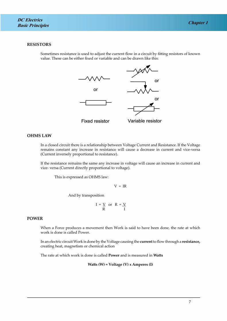
RESISTORS
Sometimes resistance is used to adjust the current flow in a circuit by fitting resistors of known value. These can be either fixed or variable and can be drawn like this:
OHMS LAW
In a closed circuit there is a relationship between Voltage Current and Resistance. If the Voltage remains constant any increase in resistance will cause a decrease in current and vice-versa (Current inversely proportional to resistance).
If the resistance remains the same any increase in voltage will cause an increase in current and vice- versa (Current directly proportional to voltage).
This is expressed as OHMS law:
V = IR
And by transposition
I = V or R = V R I
POWER
When a Force produces a movement then Work is said to have been done, the rate at which work is done is called Power.
In an electric circuit Work is done by the Voltage causing the current to flow through a resistance, creating heat, magnetism or chemical action
The rate at which work is done is called Power and is measured in Watts
Watts (W) = Voltage (V) x Amperes (I)

8
Chapter 1 DC ElectricsBasic Principles
Three formulae for calculating power can be derived from the two basic formulae V=IR and W=VxI
Voltage unknown ¾ W = I 2 R Resistance unknown ¾ W = V x I Current unknown ¾ W = V2
R
When a current passes through a resistor it becomes hot and will eventually melt if the current becomes excessive.
The amount of heat developed by a current I in a resistor R is I2 R Watts, therefore it can be seen that the heating effect is proportional to the square of the current. So a small increase in current can cause a significant increase in heating effect.
Each electrical component will be given a Power Rating (maximum wattage) which, if exceeded will cause the component to overheat, eg. 60 Watt light bulb.
Each electrical circuit in an aircraft will be protected by a fuse or circuit breaker which will prevent the maximum power rating of a component to be exceeded by breaking the circuit if the current increases.
SERIES AND PARALLEL CIRCUITS
More than one resistance can be connected in any one circuit and the may be connected in Series - one after the other, or in Parallel - alongside each other.
Series ¾
Series connection reduces current flow and therefore power consumption, but can be impractical because individual loads (resistances) cannot be individually controlled. Also the failure of one resistance would mean failure of the rest of the circuit.
The total circuit resistance can be calculated by summing the individual resistances.
RT = R1 + R2 + R3ie. RT = 4 + 6 + 10
RT = 20 ohms
V = IR so current = 12 = 0.6 amps 20

9
Chapter 1DC ElectricsBasic Principles
Parallel ¾
Parallel connection ensures each resistor is individually controllable and receives the same voltage. Failure of one resistor will not affect the others. Most aircraft loads are connected in parallel.
The total circuit resistance can be found by the following method.
1 = 1 + 1 + 1RT R1 R2 R3
1 = 1 + 1 + 1RT 4 6 10
1 = 15 + 10 + 6 RT 60
1 = 31RT 60
RT = 6031
RT = 1.94 ohms
V = IR so current = 12 = 6 amps approx 1.94
Combination of series and parallel resistors ¾
First evaluate the parallel resistors then add the result to the series resistor

10
Chapter 1 DC ElectricsBasic Principles
1 = 1 + 1 Find the lowest common denominatorRT 10 6
1 = 3 + 5 RT 30
1 = 8 RT 30
RT = 30 Therefore the total resistance for the two parallel resistors is: 8
RT = 3.75 ohms
An alternative method of calculating the resistance of 2 resistors in parallel is:
RT = R1 x R2R1 + R2
Using the above example
RT = 10 x 610 + 6
RT = 60 RT = 3.75 ohms16
Note: The total resistance of resistors in parallel is always less than the value of the lowest resistor e.g. 3.75 ohms is less than 6 ohms.
Total circuit resistance is 3.75 ohms plus 4 ohms = 7. 75 ohms
KIRCHOFF’S LAWS
First law ¾
The total current flow into a point on a circuit is equal to the current flow out of that point e.g.

11
Chapter 1DC ElectricsBasic Principles
Second law ¾
If all the voltage drops in a closed circuit are added together, their sum always equals the voltage applied to that closed circuit.
To prove Kirchoff’s 2nd Law, first we must calculate the current and therefore the total resistance
RT = R1 + R2 + R3RT = 2 + 4 + 6RT = 12 ohms
From Ohm’s Law
V = IR » I = V R
I = 12 12
I = 1 amp
We can now calculate the voltage drops throughout the circuit. At present all we know is there is 12 volts before the 2 ohm resistor and zero volts after the 6 ohm resistor.
Using Ohm’s Law V= IR. To calculate the voltage drop across the 2 ohm resistor:
V = 1 amp x 2 ohms = 2 volts
Therefore, the voltage drop is 2 volts i.e. 12 volts enters the 2 ohm resistor 10 volts exits. Using the same approach for the 4 ohm resistor:
V = 1 amp x 4 ohms = 4 volts i.e. 10 volts enters the 4 ohm resistor and 6 volts exits.
Finally, calculating the voltage drop across the 6 ohm resistor:
V = 1 amp x 6 ohms = 6 volts i.e. 6 volts enters the 6 ohm resistor and zero volts exit.
Therefore, the voltage drop in the closed circuit is 2 volts + 4 volts + 6 volts = 12 volts which equal’s the voltage applied.

12
Chapter 1 DC ElectricsBasic Principles
WHEATSTONE BRIDGE
The two statements in Kirchoff’s laws concerning the sums of currents and voltages in a circuit are useful for solving complicated problems. The arrangement of resistors below is called a Wheatstone Bridge
The Wheatstone bridge can be used to compare an unknown resistance RX with others of known values. R3 is varied until zero deflection is obtained on the ammeter. At this point the products of the diagonally opposite resistors are equal to each other because there is no current flow between point B and point C and the bridge is said to be balanced.
ie. R1 x Rx = R2 x R3 from which
Rx = R2 x R3 R1
Example:
If R3 is adjusted until the ammeter reading is zero when R3 is 3 ohms, what is the value of RX?

13
Chapter 1DC ElectricsBasic Principles
R1 x Rx = R2 x R3 from which
Rx = R2 x R3 R1
Therefore Rx = 6 x 3 4
Rx = 18 4
Rx = 4.5 ohms

14
TDC ElectricsBasic PrinciplesChapter 1
QUESTIONS – THEORY
1. All effects of electricity take place because of the existence of a tiny particle called the:
a. electric. b. proton. c. neutron. d. electron.
2. The nucleus of an atom is:
a. positively charged. b. negatively charged. c. statically charged. d. of zero potential.
3. An atom is electrically balanced when:
a. its protons and electrons balance each other. b. the protons outnumber the electrons.c. the electrons outnumber the protons.d. the electric and static charges are balanced.
4. The electrons of an atom are:
a. positively charged. b. neutral.c. negatively charged. d. of zero potential.
5. A material with a deficiency of electrons becomes:
a. positively charged. b. negatively charged.c. isolated.d. overheated.
6. A material with a surplus of electrons becomes:
a. positively charged. b. negatively charged. c. over charged.d. saturated.
7. Heat produces an electric charge when:
a. like poles are joined.b. a hard and soft glass is heated.c. the junction of two unlike metals is heated. d. hard and soft material are rubbed together.

15
Chapter 1DC ElectricsBasic Principles
8. Friction causes:
a. mobile electricity. b. basic electricity. c. static electricity. d. wild electricity.
9. Chemical action produces electricity in:
a. a light meter. b. a generator.c. a primary cell.d. starter generator.
10. A photo electric cell produces electricity when:
a. two metals are heated.b. exposed to a light source. c. a light source is removed.d. exposed to the heat of the sun.

16
TDC ElectricsBasic PrinciplesChapter 1
QUESTIONS - UNITS 1
1. The difference in electric potential is measured in:
a. KVAR’s b. wattsc. amps d. volts
2. The units of electrical power is measured in:
a. wattsb. amperes c. ohmsd. volts
3. The unit measurement of electrical resistance is:
a. the volt b. the watt c. the ohmd. the ampere
4. An ammeter measures:
a. currentb. power dissipationc. differences of electrical potential d. heat energy
5. Materials containing ‘free electrons’ are called:
a. insulators b. resistors c. collectorsd. conductors
6. The unit used for measuring the E.M.F. of electricity is:
a. the ohmb. the ampere c. the voltd. the watt
7. The unit used for measuring:
a. current - is the volt.b. resistance - is the ohm.c. electric power is the capacitor. d. E.M.F. - is the amp.

17
Chapter 1DC ElectricsBasic Principles
8. Three resistors of 60 ohms each in parallel give a total resistance of:
a. 180 ohms b. 40 ohms c. 30 ohms d. 20 ohms
9. A voltmeter measures:
a. electro-motive force.b. the heat loss in a series circuit. c. the current flow in a circuit.d. the resistance provided by the trimming devices.
10. Watts =
a. resistance squared x amps b. volts x ohmsc. ohms x amps d. volts x amps

18
TDC ElectricsBasic PrinciplesChapter 1
QUESTIONS - UNITS 2
1. The total resistance of a number of power consumer devices connected in series is:
a. the addition of the individual resistances.b. the addition of the reciprocals of the individual resistance. c. twice the reciprocal of the individual resistances.d. the reciprocal of the total.
2. The total resistance of a number of resistances connected in parallel is:
a. R = R1 + R2 + R3 + R4
b. 1 = 1 + 1 + 1 + 1 RT R1 R2 R3 R4
c. 1 = R1 + R2 + R3 + R4 RT
d. R = 1 + R2 + 1 + R4T1 R 1 R 1
3. Ohms Law states:
a. Current in amps = Resistance in ohmsElectromotive force in volts
b. Resistance in ohms = Current in ampsElectromotive force in volts
c. Current in amps = Electromotive force in voltsResistance in ohms
4. A device consuming 80 watts at 8 amps would have a voltage supply of:
a. 640 volts. b. 12 volts. c. 10 volts. d. 8 volts.
5. In a simple electrical circuit, if the resistors are in parallel, the total current consumed is equal to:
a. the sum of the currents taken by the resistors divided by the number of resistors. b. the sum of the currents taken by the resistorsc. the average current taken by the resistors times the number of the resistors. d. the sum of the reciprocals of the currents taken by the resistors
6. The symbol for volts is:
a. E or W b. V or Ec. I or V d. R or W

19
Chapter 1DC ElectricsBasic Principles
7. Electrical potential is measured in:
a. watts b. bars c. volts d. ohms
8. If a number of electrical consuming devices were connected in parallel the reciprocal of the total resistance would be:
a. the sum of the currents.b. the sum of the reciprocals of the individual resistances. c. the sum of their resistances.d. volts divided by the sum of the resistances.
9. The current flowing in an electrical circuit is measured in:
a. volts b. ohmsc. inductance d. amps
10. Electro-motive force is measured in:
a. amps x volts b. wattsc. ohms d. volts

20
TDC ElectricsBasic PrinciplesChapter 1
QUESTIONS - GENERAL
1. OHMS law is given by the formula
a. I = R V
b. V = R Ic. I = V
Rd. R = V x I
2. The current flowing in a circuit is
a. Directly proportional to resistance, indirectly proportional to voltageb. Directly proportional to temperature, inversely proportional to resistance c. Inversely proportional to resistance, directly proportional to voltaged. Inversely proportional to applied voltage, directly proportional to temperature
3. The unit of EMF is the
a. Ampere b. Voltc. Watt d. Ohm
4. Potential difference is measured in
a. Amps b. Volts c. Watts d. Ohms
5. The unit of current is the
a. Ampere b. Voltc. Watt d. Ohm
6. The unit of resistance is the
a. Ampere b. Voltc. Watt d. Ohm
7. Electrical power is measured in
a. Ampere b. Voltc. Watt d. Ohm

21
Chapter 1DC ElectricsBasic Principles
8. 1,250 ohms may also be expressed as
a. 1250 K ohms b. 1.25 K ohms c. 1.25 M ohms d. 0.125 K ohms
9. 1.5 M ohms may also be expressed as
a. 15000 ohms b. 1500 ohmsc. 150000 ohms d. 1500 K ohms
10. 550 K ohms may also be expressed as
a. 550000 M ohms b. 0.55 M ohmsc. 55000 ohms d. 0.55 ohms
11. The voltage applied to a simple resistor increases
a. Current will decrease but power consumed remains constant b. Resistance and power decreasec. Current flow will increase and power consumed will increase d. Current flow increases and power consumed decreases
12. What is the total resistance in this circuit
a. 11.5 ohmsb. 11,500 K ohms c. 11.5 K ohmsd. 11.5 M ohms
LOOK AT THE CIRCUIT AT ANNEX ‘A’ AND ANSWER THE FOLLOWING QUESTIONS
13. The total resistance of the circuit is
a. 14 ohms b. 39.6 ohms c. 25.6 ohmsd. varies with the applied voltage
14. The current flow indication on ammeter ‘A’ would be
a. 2 amps b. 2 voltsc. 2.5 amps d. 2.5 volts

22
TDC ElectricsBasic PrinciplesChapter 1
15. The total power consumed in the circuit will be
a. 14 kilowatts b. 56 kilowatts c. 56 wattsd. 14 watts
16. The power consumed by R5 alone is
a. 14 watts b. 28 watts c. 112 wattsd. 28 kilowatts
17. The indication on voltmeter V1 will be
a. 2.3 volts b. 28 volts c. 9.2 volts d. 92 volts
18. The indication on voltmeter V3 will be
a. 28 volts b. 14 volts c. 14 amps d. 3.5 volts
19. The indication on voltmeter V2 will be
a. 28 volts b. 4.8 volts c. 9.6 volts d. 14 volts
20. The current flowing through R2 is
a. 0.04 amps b. 0.4 amps c. 4 ampsd. 40 milliamps
21. The current flowing through R3 is
a. 0.04 amps b. 0.4 amps c. 4 ampsd. 40 milliamps
22. The current flowing through R4 is
a. 120 milliamps b. 1.2 ampsc. 19.2 ampsd. 1.92 milliamps

23
Chapter 1DC ElectricsBasic Principles
23. The power consumed by R2 alone is
a. 1.92 kilowatts watts b. 1.92 wattsc. 65.3 wattsd. 65.3 kilowatts
24. The power consumed by R3 alone is
a. 1.92 kilowatts watts b. 1.92 wattsc. 65.3 wattsd. 65.3 kilowatts
25. The power consumed by R4 alone is
a. 5.76 kilowatts b. 5.76 voltsc. 5.76 watts d. 3.33 watts
26. The power consumed by R1 alone is
a. 18.4 kilowatts b. 42.32 wattsc. 18.4 wattsd. 4.232 kilowatts

24
TDC ElectricsBasic PrinciplesChapter 1
ANNEX ‘A’
ANNEX ‘A’

25
Chapter 1DC ElectricsBasic Principles
ANSWERS – THEORY
1 2 3 4 5 6 7 8 9 10
D A A C A B C C C B
ANSWERS – UNITS 1
1 2 3 4 5 6 7 8 9 10
D A C A D C B D A D
ANSWERS – UNITS 2
1 2 3 4 5 6 7 8 9 10
A B C C B B C B D D
ANSWERS - GENERAL
1 2 3 4 5 6 7 8 9 10 11 12
C C B B A D C B D B C C
13. A. Total circuit resistance, evaluate the total resistance of the three resistors in parallel first
1 = 1 + 1 + 1RT R1 R2 R3
1 = 1 + 1 + 1RT 12 12 4
1 = 1 + 1 + 3 RT 12
1 = 5RT 12
RT = 12 = 2.4Ω 5
Then add the resistances in series
4.6 + 2.4 + 7 = 14Ω

26
TDC ElectricsBasic PrinciplesChapter 1
14. A. I = V = 2 amps R
15 16 17 18 19 20 21 22 23 24 25 26
C B C B B B B B B B C C

27
Chapter 2DC ElectricsSwitches
CHAPTER TWO
SWITCHES
Contents
SWITCHES . . . . . . . . . . . . . . . . . . . . . . . . . . . . . . . . . . . . . . . . . . . 29
PROXIMITY DETECTORS . . . . . . . . . . . . . . . . . . . . . . . . . . . . . . . . . . 30
TIME SWITCHES. . . . . . . . . . . . . . . . . . . . . . . . . . . . . . . . . . . . . . . . 33
CENTRIFUGAL SWITCHES . . . . . . . . . . . . . . . . . . . . . . . . . . . . . . . . . 33

28
Chapter 2 DC ElectricsSwitches

29
Chapter 2DC ElectricsSwitches
SWITCHES
The initiation and control of aircraft circuits is achieved by switches and relays. Some typical switches are described here.
Toggle switch
A general purpose switch common in older aircraft having a number of isolating contact’s inside. It can be a two position switch (on or off) or a multi position switch sprung biased to the centre or off position and then pressed and held to select in the desired direction.
Figure 2.1Figure 2.1
Switch light
Switch lights have largely replaced toggle switches in modern aircraft and combine the functions of a switch with a push action and an indicator light for the associated function.
There are two basic types
Momentary action ¾ press and hold to activate, release to deactivate.
Alternate action ¾ press and release to activate, press and release a second time to deactivate.
The indicator in the lens confirms the selected position or provides a warning which requires the switch to be selected. Figure 2.2
Figure 2.2

30
Chapter 2 DC ElectricsSwitches
Guarded Switches
Toggle switches or switch lights can be guarded to prevent inadvertent operation. eg. Generator disconnects the fuel dump master. (See previous diagram)
Micro switch
Micro switches are still used in modern aircraft to detect the position of a particular device eg. door opened or closed.
The name Micro switch describes the small movement between the ‘make and break’ position. Micro switches can activate indications on the flight deck or control relays for a sequenced operation. They are largely replaced by proximity detectors on modern aircraft.
Figure 2.3Figure 2.3
Bi-metallic switch (Thermal switch)
Bi-metallic switches are temperature sensitive switches and are activated when a certain value of temperature is reached to provide an indication to the pilot or to activate / deactivate a circuit. e.g. Fire detection circuits, battery overheat switch, oil temperature warning light.
PROXIMITY DETECTORS
Proximity Detectors are electrical or electronic sensors that respond to the presence of a material. The electrical or electronic response is used to activate a switch, relay or transistor. There are many types of proximity detectors, the major types being inductive, capacitive and magnetic. The inductive and magnetic sensors need the monitored material to be metal, but the capacitive type can monitor either metal or non-metal materials.
31
Chapter 2DC ElectricsSwitches
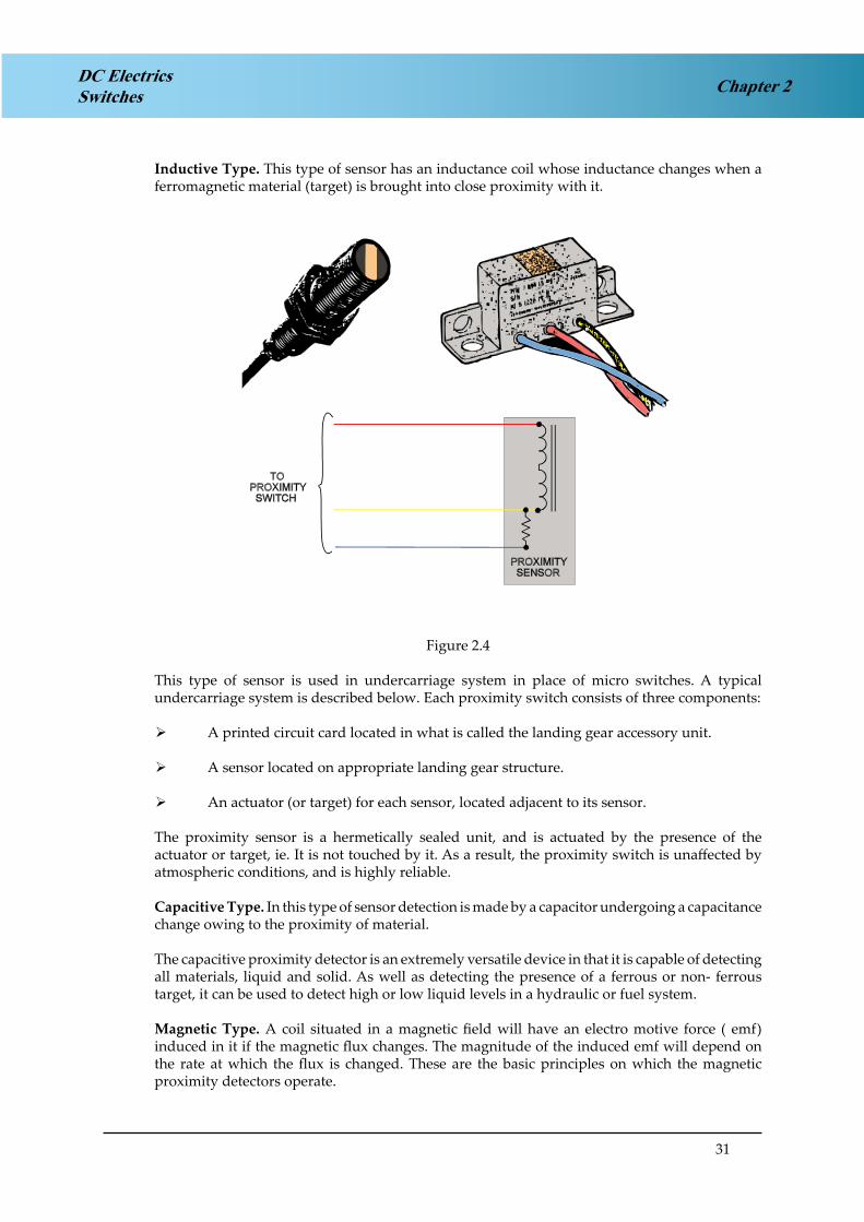
Inductive Type. This type of sensor has an inductance coil whose inductance changes when a ferromagnetic material (target) is brought into close proximity with it.
Figure 2.4
Figure 2.4
This type of sensor is used in undercarriage system in place of micro switches. A typical undercarriage system is described below. Each proximity switch consists of three components:
A printed circuit card located in what is called the landing gear accessory unit. ¾
A sensor located on appropriate landing gear structure. ¾
An actuator (or target) for each sensor, located adjacent to its sensor. ¾
The proximity sensor is a hermetically sealed unit, and is actuated by the presence of the actuator or target, ie. It is not touched by it. As a result, the proximity switch is unaffected by atmospheric conditions, and is highly reliable.
Capacitive Type. In this type of sensor detection is made by a capacitor undergoing a capacitance change owing to the proximity of material.
The capacitive proximity detector is an extremely versatile device in that it is capable of detecting all materials, liquid and solid. As well as detecting the presence of a ferrous or non- ferrous target, it can be used to detect high or low liquid levels in a hydraulic or fuel system.
Magnetic Type. A coil situated in a magnetic field will have an electro motive force ( emf) induced in it if the magnetic flux changes. The magnitude of the induced emf will depend on the rate at which the flux is changed. These are the basic principles on which the magnetic proximity detectors operate.

32
Chapter 2 DC ElectricsSwitches
In its simplest form, a coil is wound around a bar magnet and one pole of the magnet is then located close to a ferrous object. If the ferrous object moves, the flux in the magnetic changes and an emf is induced in the coil. If a number of ferrous objects move past the magnet, a train of pulses is induced in the coil.
Magnetic detectors are most commonly used in conjunction with mild steel gear wheels, each tooth in the wheel being, in effect, a ferrous object. The detector is located radially and close to the periphery of the wheel and provides an output having a frequency equal to the frequency of passage of the teeth past the detector.
Figure 2.5Figure 2.5
Figure 2.6 Landing Gear Position Sensors
Figure 2.6 Landing Gear Position Sensors

33
Chapter 2DC ElectricsSwitches
TIME SWITCHES
Time switches or relays can be initiated electrically or mechanically to activate a circuit after a specific time interval has occurred. eg. Auxiliary power unit air intake door closes 30 seconds after APU has shut down.
CENTRIFUGAL SWITCHES
These can be set to activate or de-activate a circuit as the rpm of a device increases or decreases. e.g. Starter motor cut out switch.

34
Chapter 2 DC ElectricsSwitches

35
Chapter 3DC ElectricsCircuit Protection and Capacitors
CHAPTER THREE
CIRCUIT PROTECTION and CAPACITORS
Contents
ELECTRICAL FAULTS . . . . . . . . . . . . . . . . . . . . . . . . . . . . . . . . . . . . 37
CIRCUIT PROTECTION DEVICES . . . . . . . . . . . . . . . . . . . . . . . . . . . . . 37
FUSES . . . . . . . . . . . . . . . . . . . . . . . . . . . . . . . . . . . . . . . . . . . . . . 37
THE CARTRIDGE FUSE . . . . . . . . . . . . . . . . . . . . . . . . . . . . . . . . . . . 37
SPARE FUSES. . . . . . . . . . . . . . . . . . . . . . . . . . . . . . . . . . . . . . . . . . 39
HIGH RUPTURE CAPACITY (HRC FUSES) . . . . . . . . . . . . . . . . . . . . . . . . 39
DUMMY FUSES . . . . . . . . . . . . . . . . . . . . . . . . . . . . . . . . . . . . . . . . 39
CURRENT LIMITERS . . . . . . . . . . . . . . . . . . . . . . . . . . . . . . . . . . . . . 39
CIRCUIT BREAKERS . . . . . . . . . . . . . . . . . . . . . . . . . . . . . . . . . . . . . 40
REVERSE CURRENT CIRCUIT BREAKERS . . . . . . . . . . . . . . . . . . . . . . . . 41
CAPACITORS . . . . . . . . . . . . . . . . . . . . . . . . . . . . . . . . . . . . . . . . . 42
CAPACITANCE . . . . . . . . . . . . . . . . . . . . . . . . . . . . . . . . . . . . . . . . 43
CAPACITOR IN A DC CIRCUIT . . . . . . . . . . . . . . . . . . . . . . . . . . . . . . . 43
CAPACITOR IN AN AC CIRCUIT . . . . . . . . . . . . . . . . . . . . . . . . . . . . . . 44
CAPACITORS IN PARALLEL . . . . . . . . . . . . . . . . . . . . . . . . . . . . . . . . 45
CAPACITORS IN SERIES . . . . . . . . . . . . . . . . . . . . . . . . . . . . . . . . . . . 45
QUESTIONS - CIRCUIT BREAKERS . . . . . . . . . . . . . . . . . . . . . . . . . . . . 46
QUESTIONS - FUSES . . . . . . . . . . . . . . . . . . . . . . . . . . . . . . . . . . . . . 48
ANSWERS – CIRCUIT BREAKERS . . . . . . . . . . . . . . . . . . . . . . . . . . . . . 50
ANSWERS - FUSES . . . . . . . . . . . . . . . . . . . . . . . . . . . . . . . . . . . . . . 50

36
Chapter 3 DC ElectricsCircuit Protection and Capacitors

37
Chapter 3DC ElectricsCircuit Protection and Capacitors
ELECTRICAL FAULTS
In an electrical circuit, abnormal conditions may arise for a variety of reasons, which can cause over current or over voltage conditions.
If allowed to persist, these abnormal conditions or faults will lead to damage or destruction of equipment and in extreme cases, loss of life. Certainly the essential power supplies will fail, and it is therefore necessary to protect circuits against all such faults, by the use of fuses and circuit breakers.
CIRCUIT PROTECTION DEVICES
There is a number of protection devices used in aircraft electrical systems but only 2 basic types are discussed here:
Fuses ¾Circuit breakers ¾
The fundamental difference in the type of protection provided by fuses and circuit breakers is in their time of operation relative to the attainment of maximum fault current.
A fuse normally opens the circuit before full fault current is reached, whereas the circuit breaker opens after the full fault current is reached.
This means that when circuit breakers are used as the protection device, both the circuit breaker and the component must be capable of withstanding the full fault current for a short time.
The circuit breaker has the capability, which the fuse has not, of opening and closing the circuit, and can perform many such operations before replacement is necessary, it may also be used as a circuit isolation switch.
FUSES
There are 3 basic types of fuse currently in use on aircraft:
Cartridge fuse ¾High rupture capacity (HRC) fuse ¾Current limiter fuse ¾
THE CARTRIDGE FUSE
The cartridge type fuse consists of a tubular glass or ceramic body, 2 brass end caps and a fuse element.
The element may be one of the following:
Tinned copper wire ¾Silver wire ¾A strip of pure zinc - electro tinned ¾

38
Chapter 3 DC ElectricsCircuit Protection and Capacitors
Figure 3.1. Typical Fuses, (a) A Light Duty Circuit Fuse. (b) A High RapturingCapacity Fuse.
Figure 3.1 Typical Fuses(a) A Light Duty Circuit Fuse. (b) A High Rupturing Capacity Fuse.
The latter type element is generally used in heavy duty circuits, the zinc strip being cut to a specified width.
A fuse operates when the current flowing through it is sufficient to melt the wire or strip element, the time taken varying inversely with the current.
All fuses are rated at a specific current value, i.e. the rating indicates the current they will carry continuously or intermittently without unduly heating up or deteriorating.
The rating of a fuse for a particular circuit is such that it is not less than the normal current flowing in the circuit, but that it operates ('blows') at a current level below the safety limit of the equipment or cable used.
For this reason only the specified fuse should be used in a particular circuit. The diagram shows typical aircraft fuses, the ratings can vary between 0 .5 and 500 amps, the higher ratings being limited to the HRC or current limiter types.
Fuses are made of a type of wire which has a low melting point, and when it is placed in series with the electrical load it will melt, blow or rupture when a current of higher value than its ampere rating is placed upon it.
Fuses are rated in 'amps'.
A blown fuse may be replaced with another of the correct rating once only. If it blows again when switching on there is a defect in the system and the fuse must not be changed again until the circuit has been investigated.

39
Chapter 3DC ElectricsCircuit Protection and Capacitors
SPARE FUSES
The carriage of spare fuses is mandatory, the quantity of spares being at least 10% of the number of each rating installed, with a minimum of 3 of each.
HIGH RUPTURE CAPACITY (HRC FUSES)
The high rupture capacity (HRC) fuse is an improvement on the cartridge type fuse. It is used mainly for high current rated circuits.
The body is a ceramic material of robust construction and has one or more element holes. The element holes are filled with powdered marble or clean quartz sand. The end caps are of plated brass or copper.
The HRC has the following advantages over the normal glass cartridge type:
more accurate operation ¾operates without flame ¾does not deteriorate with age ¾is more robust ¾operates rapidly ¾is not affected by ambient temperature ¾
DUMMY FUSES
Aircraft electrical circuits which are not in use will have dummy fuses fitted. If it is necessary to isolate a particular circuit by the removal of the fuse in order that the system be made ‘safe’ or for work to be carried out, a dummy fuse or fuse holder should replace the fuse which has been removed.
To distinguish the dummy fuse, a red streamer is attached to it.
Dummy fuse links are manufactured to standard fuse dimensions from red plastic, the centre portion being square in section with corrugated sides to facilitate identification.
Services protected by circuit breakers are made safe in a similar manner, a warning flag or plate is clipped to the tripped circuit breaker, indicating that the service has been rendered safe for servicing.
CURRENT LIMITERS
Current limiters, as the name suggests, are designed to limit the current to some pre-determined amperage value.
They are also thermal devices, but unlike ordinary fuses they have a high melting point, so that their time/current characteristics permit them to carry a considerable overload current before rupturing.
For this reason their application is confined to the protection of heavy-duty power distribution circuits. The output of a Transformer Rectifier Unit would be a prime location for a current limiter to be used.

40
Chapter 3 DC ElectricsCircuit Protection and Capacitors
Figure 3.2 A Typical Current Limiter (AnAirfuse).
Figure 3.2 A Typical Current Limiter (An Airfuse)
A typical current limiter (manufactured under the name of ‘Airfuse’) is illustrated in Figure 3.2, it incorporates a fusible element which is, in effect, a single strip of tinned copper, drilled and shaped at each end for form lug type connections, with the central portion ‘waisted’ to the required width to form the fusing area.
The central portion is enclosed by a rectangular ceramic housing, one side of which is furnished with an inspection window which, depending on the type, may be glass or mica.
CIRCUIT BREAKERS
Circuit breakers combine the function of fuse and switch and can be used for switching circuits on and off in certain circumstances.
They are fitted to protect equipment from damage resulting from overload, or fault conditions. The design and construction of circuit breakers is wide and varied.
Generally, the circuit breaker incorporates an automatic thermo-sensitive tripping device and a manually or electrically operated switch.
Some electrical operated circuit breakers may also include electromagnetic and reverse current tripping devices.
The smaller type single button circuit breakers shown in the diagram, range from 5 amps to 45 amps, whereas the larger reverse current circuit breakers can be rated up to 600amps.
Figure 3.3 shows two typical circuit breakers, the single push pull button type has a white marker band to assist in identifying a ‘tripped’ circuit breaker amongst a panel of many.
The circuit breaker at (b) is fitted with a “manual trip” button and is more usually associated with a heavy duty circuit.

41
Chapter 3DC ElectricsCircuit Protection and Capacitors
Figure 3.3 Circuit Breakers.Figure 3.3 Circuit Breakers.
Circuit breakers are common on the flight deck of modern aircraft and can be categorised as either:
a Non-Trip Free Circuit Breaker, or ¾a Trip Free Circuit Breaker. ¾
The non-trip free circuit breaker may be held in under fault conditions and the circuit will be made, this is clearly dangerous.
The Trip free circuit breaker if held in under the same circumstances the circuit can not be made.
Pressing the re-set button will reset either circuit breaker if the fault has been cleared.
REVERSE CURRENT CIRCUIT BREAKERS
These circuit breakers are designed to protect power supply systems and associated circuits against fault currents reversing against the normal current direction of flow of a magnitude greater than those at which cut-outs normally operate.
They are furthermore designed to remain in a “locked-out” condition to ensure complete isolation of a circuit until a fault has been cleared.

42
Chapter 3 DC ElectricsCircuit Protection and Capacitors
CAPACITORS
Introduction:
A capacitor can perform three basic functions:
Store an electrical charge by creating an electrical field between the plates. ¾Will act as if it passes Alternating Current ¾Blocks Direct Current flow ¾
Construction:
In its simplest form a capacitor consists of two metal plates separated by an insulator called adielectric. Wires connected to the plates allow the capacitor to be connected into the circuit.
Figure 3.4Figure 3.4 The construction of a simple capacitor
Symbols:
Figure 3.5 shows the electrical circuit symbols for various capacitors. With the polarised capacitor it is important to connect the positive terminal to the positive supply. Non-polarised types can be connected either way round.
Figure 3.5 CAPACITOR SYMBOLS
Figure 3.5 Capacitor Symbols

43
Chapter 3DC ElectricsCircuit Protection and Capacitors
CAPACITANCE
The capacitance (C) of a capacitor measures its ability to store an electrical charge. The unit of capacitance is the FARAD (F). The farad is subdivided into smaller, more convenient units.
1 micro farad (1µF) = 1 millionth of a farad = 10-6 F1 nano farad (1nF) = 1 thousand millionth of a farad = 10-9 F1 picofarad (1pF) = 1 millionth millionth of a farad = 10-12 F
Factors Affecting Capacitance:
Area of the plates - a large area gives a large capacitance ¾
Distance between the plates - a small distance gives a large capacitance ¾
Material of the dielectric - different materials have different values of capacitance, for ¾example paper, mica, air and fuel. The value of the dielectric is referred to as the di-electric constant (k). For example, waxed paper has a k value of about 3, whereas air has a k of 1. So a capacitor having waxed paper as its dielectric would have 3 times the capacitance of the same capacitor having air as its dielectric.
Working Voltage:
This is the largest voltage DC or Peak AC which can be applied across the capacitor. It is often marked on the case of the capacitor and if it is exceeded the dielectric may break down and permanent damage result.
CAPACITOR IN A DC CIRCUIT
Figure 3.6 shows a capacitor in series with a battery and a switch. If the switch is closed electrons are pushed by the battery on to plate Y building up a negative charge. This charge exerts a repelling force across the dielectric which causes electrons to leave the plate X and be attracted to the positive plate of the battery. While this charging action is taking place electrons are passing through the connecting wires but no current flows through the dielectric.
Figure 3.6
Figure 3.6
44
Chapter 3 DC ElectricsCircuit Protection and Capacitors
After a short time the difference in charge between the plates results in a potential difference existing between the plates. The flow of electrons will reduce and stop when the potential difference between the plates is equal to the supply voltage. The capacitor is now fully charged, current has stopped flowing, the plates are said to be charged and there exists an electric field between the plates. The capacitor is now blocking DC flow.
If the switch is opened and the capacitor is disconnected from the battery it holds its charge: a capacitor stores electrical energy by the formation of an electric field between the plates. The capacitor will only discharge if it is now connected to an external circuit.
CAPACITOR IN AN AC CIRCUIT
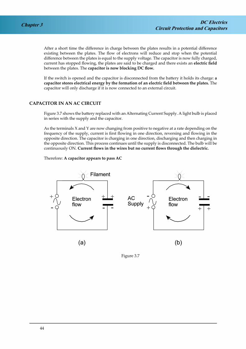
Figure 3.7 shows the battery replaced with an Alternating Current Supply. A light bulb is placed in series with the supply and the capacitor.
As the terminals X and Y are now changing from positive to negative at a rate depending on the frequency of the supply, current is first flowing in one direction, reversing and flowing in the opposite direction. The capacitor is charging in one direction, discharging and then charging in the opposite direction. This process continues until the supply is disconnected. The bulb will be continuously ON. Current flows in the wires but no current flows through the dielectric.
Therefore: A capacitor appears to pass AC
Figure 3.7
Figure 3.7

45
Chapter 3DC ElectricsCircuit Protection and Capacitors
CAPACITORS IN PARALLEL
Capacitors connected in parallel are effectively increasing the area of the plates. The total capacitance Ct can be found by adding the individual capacitances:
CT = C1 + C2 etc
Figure 3.8Figure 3.8
CAPACITORS IN SERIES
Capacitors in series have effectively increased the distance between the plates and therefore the total capacitance has decreased. The total capacitance is found by using the formula for resistances in parallel:
1 = 1 + 1 CT C1 C2
etc
Figure 3.9Figure 3.9

46
DC ElectricsCircuit Protection and CapacitorsChapter 3
QUESTIONS - CIRCUIT BREAKERS
1. In a circuit fitted with a non trip free circuit breaker if a fault occurs and persists:
a. if the reset button is depressed and held in, the circuit will be made. b. the trip button may be pressed to reset, but not permanently.c. a non trip free circuit breaker can never be by-passed.d. the reset button may be pressed to make the circuit permanent.
2. A trip-free circuit breaker that has tripped due to overload:
a. can be reset and held in during rectification. b. can never be reset.c. can be reset after overhaul.d. maybe reset manually after fault has been cleared.
3. Circuit breakers and fuses
a. are used in DC circuits only b. are used in AC or DC circuits c. are used in AC circuits onlyd. are used in low current circuits only
4. A trip-free circuit breaker is one which:
a. cannot be reset by holding the lever in while the fault persists. b. can be reset by holding the lever in while the fault persists.c. must be held in during checks to find faults. d. can be by passed.
5. If the reset button is pressed in the trip-free circuit breaker, the contacts with the fault cleared will:
a. be made and kept made.b. only be made if there is a fuse in the circuit. c. reset itself only after a delay of 20 seconds.d. not be made and the reset will remain inoperative.
6. A circuit breaker is a device for:
a. controlling rotor movement only. b. isolating the service on overload.c. isolating the battery when using the ground batteries. d. earthing the magnetos when switching off.
7. A non-trip free circuit breaker is:
a. one which can make a circuit in flight by pushing a button. b. a wire placed in a conductor which melts under overload. c. another type of voltage regulator.d. an on-off type tumbler switch.

47
Chapter 3DC ElectricsCircuit Protection and Capacitors
8. A non-trip-free circuit breaker that has tripped due to overload:
a. can never be reset.b. can only be reset on the ground by a maintenance engineer. c. can be reset and held in if necessary.d. cannot be reset while the fault is still there.
9. A thermal circuit breaker works on the principle of:
a. differential expansion of metals. b. differential thickness of metals. c. differential density of metals.d. differential pressure of metals.
10. Circuit breakers are fitted in:
a. series with the load. b. parallel with the load. c. across the load.d. shunt with the load.

48
DC ElectricsCircuit Protection and CapacitorsChapter 3
QUESTIONS - FUSES
1. A fuse is said to have blown when:
a. an excess current has burst the outer cover and disconnected the circuit from the supply.
b. the circuit is reconnected.c. a current of a higher value than the fuse rating has melted the conductor and disconnected
the circuit from the supply.d. the amperage has been sufficiently high to cause the fuse to trip out of its holder and has
therefore, disconnected the circuit from the supply.
2. In a fused circuit the fuse is:
a. in parallel with the load. b. in series with the load.c. in the conductor between generator and regulator. d. only fitted when loads are in series.
3. Overloading an electrical circuit causes the fuse to ‘Blow’. This:
a. increases the weight of the insulation. b. fractures the fuse case.c. disconnects the fuse from its holder. d. melts the fuse wire.
4. What must be checked before replacing a fuse:
a. the ohms of the circuit.b. the amps being used in the circuit.c. the amps capacity of the consuming device in the circuit. d. the correct fuse volt or watts rating.
5. The size of fuse required for an electrical circuit whose power is 72 watts and whose voltage is24 volts is:
a. 24 amps b. 10 amps c. 5 amps d. 15 amps
6. When selecting a fuse for an aircraft circuit the governing factor is:
a. the voltage of the circuit. b. cable cross sectional area. c. resistance of the circuit.d. power requirements of the circuit.
7. A fuse in an electrical circuit is ‘Blown’ by:
a. cooler air.b. the breaking of the glass tube.c. excess voltage breaking the fuse wire. d. excess current rupturing the fuse wire.

49
Chapter 3DC ElectricsCircuit Protection and Capacitors
8. A fuse is used to protect an electrical circuit, it is:
a. of low melting point. b. of high capacity.c. of high melting point. d. of low resistance.
9. Fuses:
a. protect the load. b. protect the cable.c. protect the generator.d. protect both the circuit cable and load.
10. A current limiter:
a. is a fuse with a low melting point. b. is a circuit breaker.c. is a fuse with a high melting point.d. is a fuse enclosed in a quartz or sand.

50
DC ElectricsCircuit Protection and CapacitorsChapter 3
ANSWERS – CIRCUIT BREAKERS
1 A
2 D
3 B
4 A
5 A
6 B
7 A
8 D
9 A
10 A
ANSWERS - FUSES
1 C
2 B
3 D
4 C
5 C
6 D
7 D
8 A
9 D
10 C

51
Chapter 4DC ElectricsBatteries
CHAPTER FOUR
BATTERIES
Contents
BATTERIES . . . . . . . . . . . . . . . . . . . . . . . . . . . . . . . . . . . . . . . . . . . 53
SECONDARY CELLS . . . . . . . . . . . . . . . . . . . . . . . . . . . . . . . . . . . . . 54
LEAD ACID BATTERY . . . . . . . . . . . . . . . . . . . . . . . . . . . . . . . . . . . . 55
ALKALINE BATTERY (NICKEL CADMIUM, Ni-Cad) . . . . . . . . . . . . . . . . . . 58
BATTERY CHECKS . . . . . . . . . . . . . . . . . . . . . . . . . . . . . . . . . . . . . . 59
BATTERY CHARGING . . . . . . . . . . . . . . . . . . . . . . . . . . . . . . . . . . . . 59
SECONDARY BATTERIES SUMMARY . . . . . . . . . . . . . . . . . . . . . . . . . . . 60
QUESTIONS - BATTERIES 1 . . . . . . . . . . . . . . . . . . . . . . . . . . . . . . . . . 61
QUESTIONS - BATTERIES 2 . . . . . . . . . . . . . . . . . . . . . . . . . . . . . . . . . 63
QUESTIONS - BATTERIES 3 . . . . . . . . . . . . . . . . . . . . . . . . . . . . . . . . . 65
ANSWERS – BATTERIES 1 . . . . . . . . . . . . . . . . . . . . . . . . . . . . . . . . . . 67
ANSWERS – BATTERIES 2 . . . . . . . . . . . . . . . . . . . . . . . . . . . . . . . . . . 67
ANSWERS – BATTERIES 3 . . . . . . . . . . . . . . . . . . . . . . . . . . . . . . . . . . 68

52
Chapter 4 DC ElectricsBatteries

53
Chapter 4DC ElectricsBatteries
BATTERIES
The purpose of a battery in an aircraft is to provide an emergency source of power when the generator is not running and to provide power to start the engine.
A battery is made up of a number of cells which convert chemical energy into electrical energy by a transfer of electrons from one material to another causing a potential difference between them. During the transfer of electrons the chemical composition of the two materials changes.
Primary CellA primary cell consists of two electrodes immersed in a chemical called an electrolyte. The electrolyte encourages electron transfer between the electrodes until there is a potential difference between them. When the electron transfer ceases the cell is fully charged and the potential difference is approximately 1.5 volts between the two electrodes.
Figure 4.1. A Primary CellFigure 4.1 A Primary Cell
When the positive and negative terminals are connected to an external circuit electrons flow from the negative terminal to the positive terminal through the circuit. At the same time more electrons are allowed to transfer inside the cell from the positive electrode to the negative electrode. As this circulation of electrons continues the negative electron slowly dissolves in the electrolyte until it is eventually eaten away and the cell is then “dead” and is discarded. Primary cells cannot be recharged.
Figure 4.2. A Dry Cell (Primary)Figure 4.2 A Dry Cell (Primary)

54
Chapter 4 DC ElectricsBatteries
SECONDARY CELLS
Secondary cells work on the same principle as primary cells but the chemical energy in the cell can be restored when the cell has been discharged by passing a “charging current” through the cell in the reverse direction to that of the discharge current. In this way the secondary cell can be discharged and recharged many times over a long period of time
During recharging electrical energy is converted into chemical energy which is retained until the cell is discharged again.
The Capacity of a cell is a measure of how much current a cell can provide in a certain time. Capacity is measured in Ampere hours (Ah) and is determined by the area of the plates, the bigger the cell the greater its capacity.
A cell with a capacity of 80 Ah should provide a current of 8A for 10 hours, or 80 A for 1 hr. Theoretically that should be true but in practice the capacity will reduce as the rate of discharge is increased. Capacity is normally measured at the 1 hour rate.
A single cell battery may be used on its own or cells may be connected in series, or in parallel depending on the voltage and capacity required
For cells in series the positive terminal of one cell is connected to the negative terminal of the next and so on. The total voltage is the sum of the individual cell voltages. But the capacity is that of one cell.
For cells in parallel the positive terminals are joined together and the negative terminals are joined together. The total voltage is that of one cell but the capacity is the sum of the individual cell capacities.
Figure 4.3Figure 4.3

55
Chapter 4DC ElectricsBatteries
LEAD ACID BATTERY
Figure 4.4Figure 4.4
One of the most common types of secondary cell is the Lead Acid cell.
The active material of the positive plate is lead peroxide and the negative plate is spongy lead, both plates are immersed in an electrolyte solution of water and sulphuric acid. The container is glass or hard plastic with a filler cap to allow replenishment of distilled water, which is lost through evaporation during use. A vent hole in the cap allows the escape of hydrogen gas, which is produced when the cell is working
The state of charge of a lead acid cell can be determined by measuring the strength of the electrolyte solution. This is done with a hydrometer which measures the specific gravity. A fully charged cell will have a specific gravity (SG) of 1.27, a discharged cell will have a specific gravity (SG) of 1.17.
When the cell is connected to an external circuit and current is flowing lead sulphate is formed at both plates and the specific gravity will fall as the acid becomes weaker. When the specific gravity (SG) has fallen to 1.17 and the voltage to 1.8 volts the cell should be recharged.
To charge a cell it is connected to a battery charger which applies a slightly higher voltage to the cell and causes current to flow in the reverse direction through the cell. While this is happening the lead sulphate which had been deposited on the plates is removed and the specific gravity (SG) of the electrolyte rises to 1.27. The voltage ‘on load’ should have returned to just above 2volts.
When charging a lead-acid battery it is important that the rate of charge is controlled. Charging too quickly can cause ‘gassing’ and evaporation to occur which may lead to boiling the battery dry and causing damage to the plates.

56
Chapter 4 DC ElectricsBatteries
Figure 4.5. A Lead Acid Secondary Cell.Figure 4.5 A Lead Acid Secondary Cell.
The specific gravity of the electrolyte is an indication of the battery’s state of charge or serviceability. The value of the specific gravity is checked using a hydrometer. The level of the electrolyte is maintained just above the top of the plates by topping up with distilled water. Loss of water is caused by gassing at the plates when fully charged.
The on load/nominal voltage of each cell of a lead acid battery is 2 volts.
The off-load voltage of each cell of a lead acid battery is 2.2 volts.
Electrolytes are highly corrosive and if spilled in aircraft can cause extensive damage.
The neutralising agent to be used for an acid electrolyte is a sodium bicarbonate solution. The performance of a battery is affected by temperature. In low temperatures the rate of discharge is decreased because of higher internal resistance. In warm temperatures the battery rate of discharge will increase. In general the battery performs better in warm temperatures (just like a car battery). As a lead acid battery discharges the specific gravity of the electrolyte reduces. In freezing temperatures with a discharged battery there is a risk of the electrolyte freezing. It is therefore important to maintain the battery in a fully charged state during winter operations.
Figure 4.6 shows free liquid type of lead acid battery where the electrolyte is in liquid form and Figure 4.7 shows an absorbed liquid type of lead acid battery where the electrolyte is absorbed into the active materials in the plates making it less prone to spillage.

57
Chapter 4DC ElectricsBatteries
Figure 4.6. Lead Acid Battery (Free Liquid Type).Figure 4.6 Lead Acid Battery (Free Liquid Type)
Figure 4.7 Lead Acid battery (Absorbed Liquid Type)

58
Chapter 4 DC ElectricsBatteries
ALKALINE BATTERY (NICKEL CADMIUM, Ni-Cad)
Lead acid batteries are still used in some smaller aircraft but have been largely replaced by Nickel Cadmium (alkaline type) batteries. These use different materials for their plates and electrolyte. The plates are nickel oxide and cadmium and the electrolyte is potassium hydroxide. The Specific Gravity (SG) of the electrolyte is 1.24 - 1.30
The on load voltage of one cell is about 1.2 volts.
Unlike the lead acid battery, the relative SG of the nickel-cadmium battery electrolyte does not change and the voltage variation from “fully charged” to “fully discharged,” is very slight. The only way to determine the state of charge is to carry out a measured discharge test i.e. a capacity test.
The terminal voltage remains substantially constant at 1.2volts throughout most of the discharge. Due to its low internal resistance it is also capable of supplying high current during its discharge cycle and low current during recharging without violent fluctuations of terminal voltage.
NiCad batteries have a low thermal capacity; the heat generated in certain conditions is faster than it can dissipate, so causing a rapid increase in temperature.
This has the effect of lowering the effective internal resistance thus allowing an ever increasing charging current, which, unless checked, leads to the total destruction of the battery.
This condition is known as a thermal runaway, and can cause so much heat that the battery may explode. For this reason the charging of the battery must be closely monitored and includes some safety features
A built-in thermal switch monitors the temperature and operates on a pre-set value of temperature. This effectively isolates the battery from the charging source until a reduction in temperature reverts the switch back to its normal position. Associated with the temperature switch may be an indicator light on the flight deck to alert the pilot.
The nickel cadmium battery, however, is more robust and can hold a constant terminal voltage much better during the discharge cycle. It is therefore much preferred in large modern aircraft because in the event of a total failure of the aircraft generators the Ni-Cad battery will provide a much more stable voltage.
Figure 4.8 is a graphical representation of a comparison of the discharge voltage of a lead acid against a Ni-cad during discharge.
Figure 4.8Figure 4.8

59
Chapter 4DC ElectricsBatteries
BATTERY CHECKS
The Capacity of a battery is the product of the load in amperes that the manufacturers state it will deliver, and the time in hours that the battery is capable of supplying that load.
The capacity is measured in ampere hours (A/H).
A 40 A/H battery when discharged at the 1 hour rate should supply 40 amps for the 1 hour. This is known as the ‘rated load’. Alternatively the battery could supply 4 amps for 10 hours at the 10 hour rate.
Actual Capacity is determined by the battery’s deterioration in service. If a 60 A/H battery when discharged at the 1 hour rate lasts only for .7 hour, or 42 minutes, then the actual capacity is 70% of its rated capacity. In other words, the battery is only 70% efficient.
A Capacity Test, a test to determine the actual capacity of aircraft batteries, is carried out every 3 months and the efficiency must be 80% or more for the battery to remain in service.
This capacity will ensure that essential loads can be supplied for a period of 30 minutes following a generator failure.
Loads(electrical equipment) would include;- attitude information, essential communication equipment, lighting, pitot heat, plus any other services necessary for continued safe flight, or loads which cannot easily be switched of (load shedding).
Spare batteries will be held ready for use in the electrical workshop. Lead acid batteries are stored in a charged state to prevent deterioration of the battery by sulphation. Ni-Cad batteries can be stored in a discharged state with no detrimental effect to the battery and therefore have a longer storage life or ‘shelf life’.
The On-load Check is carried out by applying the rated load to the battery circuit for a short period of time, during which time the battery voltmeter reading must remain constant and not fall below a stated value. Modern aircraft use times as low as 10-20 seconds with the rated load selected.
The pilots Pre-Flight check of a battery may include comparing the ‘on load’ voltage with the‘off load’ voltage to give an indication of the state of charge of the battery.
If the battery is not supplying any load then it is likely to show its nominal voltage,(off load voltage) if the battery is then loaded up by switching on selective loads (e.g. pitot heater, landing lights, blower motors) and the voltage is maintained then the battery is in a good state of charge. If the voltage falls below a stated value within a time limit determined by the manual then the battery is in a low state of charge and should be replaced.
BATTERY CHARGING
A Constant Voltage Charging system is employed with most lead acid batteries to maintain the battery in a fully charged condition during flight. With this system the output voltage of the generator is maintained constant at 14 volts for a 12 volt battery and 28 volts for a 24 volt battery.
The generator voltage exceeds the battery voltage by 2 volts for every 12 volts of battery potential.

60
Chapter 4 DC ElectricsBatteries
With alkaline batteries which are susceptible to thermal runaway it may be that a constant current charging system is employed by a dedicated battery charger which monitors battery temperature and voltage. Some charging systems use a method known as pulse charging and once the battery is up to 85% capacity, the battery charger delivers short pulses of charging current.
NOTE: After starting an engine using the aircraft’s battery, whether it is a lead acid battery or an alkaline battery, the generator, when it is on line, recharges that battery.
This is indicated by the high initial reading on the generator’s ammeter (load ammeter) or the battery ammeter (centre zero). This reading should quickly reduce as the battery is recharged, but if the charge rate increases, or remains high, it could be an indication of a faulty battery.
A high charge rate could result in a battery overheating and subsequent damage.
SECONDARY BATTERIES SUMMARY
Figure 4.9 Secondary Batteries SummaryFigure 4.9 Secondary Batteries Summary

61
Chapter 4DC ElectricsBatteries
QUESTIONS - BATTERIES 1
1. Battery voltage is tested with:
a. a megometer.b. a voltmeter on rated load.c. an ammeter with a rated voltage. d. a hygrometer.
2. Two 12V 40 amp/hour batteries connected in series will produce:
a. 12V 80 amp/hr b. 12V 20 amp/hr c. 24V 80 amp/hr d. 24V 40 amp/hr
3. Two 12V 40 amp/hour batteries connected in parallel will produce:
a. 12V 80 amp/hr b. 24V 80 amp/hr c. 12V 20 amp/hr d. 24V 40 amp/hr
4. A battery capacity test is carried out:
a. 6 monthly b. 2 monthly c. 3 monthlyd. every minor check
5. An aircraft has three batteries each of 12 volts with 40 amp/hr capacity connected in series. The resultant unit has:
a. a voltage of 36 and a capacity of 120 amp/hr. b. a capacity of 120 amp/hr and a voltage of 12. c. a capacity of 36 amp/hr and 120 watts.d. a voltage of 36 and a capacity of 40 amp/hr.
6. An aircraft has a battery with a capacity of 40 amp/hr. Assuming that it will provide its normal capacity and is discharged at the 10 hour rate:
a. it will pass 40 amps for 10 hrs. b. it will pass 10 amps for 4 hrs. c. it will pass 4 amps for 10 hrs. d. it will pass 40 amps for 1 hr.
7. Battery capacity percentage efficiency must always be:
a. 10% above saturation level b. above 70%c. above 80%d. above 90%

62
DC ElectricsBatteriesChapter 4
8. The method of ascertaining the voltage of a standard aircraft lead-acid battery is by checking:
a. the voltage on open circuit.b. the current flow with a rated voltage charge. c. the voltage off load.d. the voltage with rated load switched ON.
9. A battery is checked for serviceability by:
a. using an ammeter.b. measuring the specific gravity of the electrolyte. c. a boric acid solution.d. using an ohmmeter.
10. In an AC circuit:
a. the battery is connected in series.b. a battery cannot be used because the wire is too thick. c. a battery cannot be used because it is DC.d. only NICAD batteries can be used.

63
Chapter 4DC ElectricsBatteries
QUESTIONS - BATTERIES 2
1. The specific gravity of a fully charged lead acid cell is:
a. 1.270 b. 1.090 c. 1.120 d. 0.1270
2. The nominal voltage of the lead acid cell is:
a. 1.2 volts b. 1.5 volts c. 1.8 volts d. 2.0 volts
3. A lead acid battery voltage should be checked:
a. on open circuitb. using a trimmer circuit c. with an ammeterd. on load
4. In an aircraft having a battery of 24 volts nominal ( off load. and fully charged the voltmeter would read:
a. 22 volts b. 24 volts c. 26 volts d. 28 volts
5. The system used to maintain aircraft batteries in a high state of charge is the:
a. constant current system. b. constant load system.c. constant resistance system. d. constant voltage system.
6. If you connect two identical batteries in series it will:
a. double the volts and halve the capacity. b. reduce the voltage by 50%.c. double the volts and leave the capacity the same.d. double the volts and double the amps flowing in a circuit with twice the resistance.
7. The nominal voltage of an alkaline cell is:
a. 2.2 volts b. 1.8 volts c. 1.2 volts d. 0.12 volts

64
DC ElectricsBatteriesChapter 4
8. The specific gravity of a fully charged alkaline cell is:
a. 0.120 - 0.130b. 1.160c. 1.240 - 1.30d. 1.800
9. The electrolyte used in the lead acid cell is diluted:
a. hydrochloric acid. b. sulphuric acid.c. boric acid.d. potassium hydroxide.
10. The electrolyte used in an alkaline battery is diluted:
a. a saline solution. b. sulphuric acid.c. cadmium and distilled water. d. potassium hydroxide solution.

65
Chapter 4DC ElectricsBatteries
QUESTIONS - BATTERIES 3
1. The number of lead acid cells required to make up a Twelve Volt Battery is:
a. 8 b. 12 c. 6 d. 10
2. A Voltmeter across the terminals of a battery with all services off will indicate:
a. electromotive force. b. resistance.c. a flat battery.d. residual voltage.
3. The voltage of a secondary cell is:
a. determined by the number of plates. b. determined by the area of the plates.c. determined by the diameter of the main terminals. d. determined by the active materials on the plates.
4. The level of the electrolyte must be maintained:
a. just below the top plate.b. above the plates level with the filler cap. c. one inch below the top of the plates.d. just above the top of the plates.
5. To top up the electrolyte add:
a. sulphuric acid. b. distilled water.c. sulphuric acid diluted with distilled water. d. boric acid.
6. Non-spill vents are used on aircraft batteries to:
a. prevent spillage of electrolyte during violent manoeuvres. b. stop spillage of the water only.c. prevent the escape of gases.d. prevent spillage during topping-up.
7. The capacity of a lead acid battery is:
a. determined by the area of the plates.b. determined by the active materials on the plates. c. determined by the size of the series coupling bars. d. determined by the number of separators.

66
DC ElectricsBatteriesChapter 4
8. Acid spillage in an aircraft can be neutralised by using:
a. caustic soda.b. soap and water. c. soda and water.d. bicarbonate of soda and water.
9. When the battery master switch is switched off in flight:
a. the generators are disconnected from the bus bar. b. the ammeter reads maximum.c. the battery is isolated from the bus bar.d. the battery is discharged through the bonding circuit diodes.
10. When the generator is on line the battery is:
a. in parallel with the other loads. b. in series with the generator.c. in series when the generator is on line and is relayed when the generator is off line. d. load sharing.

67
Chapter 4DC ElectricsBatteries
ANSWERS – BATTERIES 1
1 B2 D3 A4 C5 D6 C7 C8 D9 B10 C
ANSWERS – BATTERIES 2
1 A2 D3 D4 C5 D6 C7 C8 C9 B10 D

68
DC ElectricsBatteriesChapter 4
ANSWERS – BATTERIES 3
1 C2 A3 D4 D5 B6 A7 A8 D9 C10 A

69
Chapter 5DC ElectricsMagnetism
CHAPTER FIVE
MAGNETISM
Contents
MAGNETISM. . . . . . . . . . . . . . . . . . . . . . . . . . . . . . . . . . . . . . . . . . 71
TEMPORARY MAGNETS. . . . . . . . . . . . . . . . . . . . . . . . . . . . . . . . . . . 72
PERMANENT MAGNETS . . . . . . . . . . . . . . . . . . . . . . . . . . . . . . . . . . 72
PERMEABILITY . . . . . . . . . . . . . . . . . . . . . . . . . . . . . . . . . . . . . . . . 73
MAGNETISM. . . . . . . . . . . . . . . . . . . . . . . . . . . . . . . . . . . . . . . . . . 73
THE MOLECULAR STRUCTURE OF MAGNETS . . . . . . . . . . . . . . . . . . . . . 73
THE MAGNETIC EFFECT OF A CURRENT . . . . . . . . . . . . . . . . . . . . . . . . 74
THE CORKSCREW RULE. . . . . . . . . . . . . . . . . . . . . . . . . . . . . . . . . . . 74
THE MAGNETIC FIELD OF A SOLENOID. . . . . . . . . . . . . . . . . . . . . . . . . 76
THE RIGHT HAND GRASP RULE . . . . . . . . . . . . . . . . . . . . . . . . . . . . . 76
THE STRENGTH OF THE FIELD OF A SOLENOID . . . . . . . . . . . . . . . . . . . 76
SOLENOID AND RELAY . . . . . . . . . . . . . . . . . . . . . . . . . . . . . . . . . . . 76
THE FORCES ON A CONDUCTOR WHICH IS CARRYING A CURRENT . . . . . . 77
QUESTIONS . . . . . . . . . . . . . . . . . . . . . . . . . . . . . . . . . . . . . . . . . . 78
ANSWERS . . . . . . . . . . . . . . . . . . . . . . . . . . . . . . . . . . . . . . . . . . . 80

70
Chapter 5 DC ElectricsMagnetism

71
Chapter 5DC ElectricsMagnetism
MAGNETISM
A magnet has the following properties:
It will attract and pick up bits of iron and steel. ¾
If freely suspended, it will come to rest pointing in a N-S direction. ¾
A magnetic field (a region surrounding a magnet in which its magnetic effects can be ¾detected.
If iron filings are sprinkled on to a sheet of paper which is placed over a magnet, the filings arrange themselves into a distinctive pattern. They trace out invisible lines of influence in the magnetic field. These lines are called lines of flux or lines of force.
We can give direction to the lines of flux by putting arrowheads on them in the direction a compass needle would point if placed in the magnetic field.
Lines of flux of a magnet emerge from the N pole and re-enter at the S pole.
Although, in diagrams, some lines of flux are shown incomplete they are in fact always continuous.
Lines of flux never cross
When two magnets are brought close together their resultant field is modified by the fact that lines of flux cannot cross. Where lines of flux from the two magnets are in the same direction they reinforce one another and the flux density is increased.
When lines of flux from the two magnets oppose one another they tend to cancel each other out. Magnetic effects are most powerful at two points, usually near the ends of the magnet, called the poles of the magnet.
When a magnet is freely suspended and comes to rest, the end nearest to the earth’s magnetic north pole is called the ‘north seeking’ or North (N) pole of the magnet. The other is the South(S) pole. If the N pole of a magnet is brought near the N pole of another magnet, the two poles repel each other. Similarly two S poles repel each other.
Attraction occurs between a N and a S pole.
LIKE POLES REPEL
UNLIKE POLES ATTRACT

72
Chapter 5 DC ElectricsMagnetism
Figure 5.1. Flux DistributionFigure 5.1 Flux Distribution
TEMPORARY MAGNETS
Temporary magnets are made from soft iron which is easily magnetised but readily loses its magnetic properties.
PERMANENT MAGNETS
Permanent magnets are made from hard alloy steels which are difficult to magnetise but retain their magnetism well.
Figure 5.2. Temporary MagnetFigure 5.2 Temporary Magnet

73
Chapter 5DC ElectricsMagnetism
PERMEABILITY
If an unmagnetised piece of soft iron is placed in a magnetic field, the lines of flux concentrate to flow through the iron. The iron itself becomes magnetised and produces additional lines of flux.
This property of increasing the flux density is called permeability.
If it is removed from the magnetic field, the soft iron loses most of its magnetism. Soft iron is said to have low magnetic retentivity. The little magnetism which remains is called its residual magnetism.
MAGNETISM
Magnetism may be destroyed by:
Heating the material. ¾
Hammering the material. ¾
Placing the material inside a solenoid which is supplied with an alternating current. ¾
THE MOLECULAR STRUCTURE OF MAGNETS
In an unmagnetised piece of soft iron, the molecules tend to form closed chains. When the iron is magnetised, the magnetised molecules tend to line up with invisible lines of influence in the magnetic field which are called the lines of flux. When all the molecules line up, the magnet is said to be saturated and it cannot be magnetised further.
N S
N
N S
N S
S N S N S N
N SN SN SS
S N S N S N
NN SN SS
S N S N S N S
NN SN SS
N S N SN S
UNMAGNETISED MAGNETISED
SATURATED
Figure 5.3. Molecular DistributionFigure 5.3 Molecular Distribution

74
Chapter 5 DC ElectricsMagnetism
THE MAGNETIC EFFECT OF A CURRENT
When a conductor carries a current, a magnetic field is set up about the conductor in the form of concentric lines of flux.
CURRENT FLOW
FIELD
Figure 5.4. Magnetic Effect of a CurrentFigure 5.4 Magnetic Effect of a Current
THE CORKSCREW RULE
If a right-handed corkscrew is turned so as to move in the direction of the conventional current in the conductor, the direction of rotation of the corkscrew is the direction of the lines of flux.
INTO PAPER
OUT OF PAPER
Figure 5.5. Direction of Current FlowFigure 5.5 Direction of Current Flow

75
Chapter 5DC ElectricsMagnetism
Figure 5.6. Combined Magnetic FieldsFigure 5.6 Combined Magnetic Fields
S
Figure 5.7. Magnetic Field in a CoilFigure 5.7 Magnetic Field in a Coil

76
Chapter 5 DC ElectricsMagnetism
THE MAGNETIC FIELD OF A SOLENOID
A solenoid (electromagnet) is a coil of a large number of turns of insulated wire. Between the coils the flux cancels out. The field pattern is similar to that of a bar magnet. The polarity of a solenoid may be found by the Right Hand Grasp Rule. Electromagnets and the principle of electromagnetism play a vital part in the operation and control of many aircraft electrical circuits.
THE RIGHT HAND GRASP RULE
If a solenoid is held in the right hand so that the fingers are curled round it pointing in the direction of the conventional current, the outstretched thumb points to the North pole of the solenoid.
THE STRENGTH OF THE FIELD OF A SOLENOID
The strength of the field of a solenoid can be increased by:
increasing the number of turns on the coil. ¾increasing the current ¾using a soft iron core. ¾
When the current is switched off the magnetic field collapses leaving a little residual magnetism in the soft iron core.
SOLENOID AND RELAY
Solenoids and relays are nothing more than remotely controlled switches. By switching a small current from the flight deck a large current can be switched at the solenoid or relay. eg. The starter solenoid in the starting circuit for a piston engine.
The solenoid has a moving core whereas the relay has a stationary core and an attracted armature.
The wires that form the coil of the solenoid or relay are insulated and have no physical or electrical contact with the circuit which is controlled by the contacts.
Figure 5.8. Solenoid and RelayFigure 5.8 Solenoid and Relay

77
Chapter 5DC ElectricsMagnetism
THE FORCES ON A CONDUCTOR WHICH IS CARRYING A CURRENT
If a current carrying conductor is placed between two magnets, the interaction of the two magnetic fields will produce a strong magnetic field on one side of the conductor and a weak magnetic field on the other. The resultant stronger force will cause the conductor to move.
This is the basic motor principle and the direction of movement can be deduced by usingFleming’s Left Hand Rule. This will be explained in the section dealing with motors.
S
S
FIELDSTRENGTHENED
FIELD WEAKENEDCONDUCTOR MOVESIN DIRECTION OFARROW
Figure 5.9. Interaction Between Two Magnetic FieldsFigure 5.9 Interaction between Two Magnetic Fields

78
DC ElectricsMagnetismChapter 5
QUESTIONS
1. The area of force around a magnet is termed:
a. conductance. b. stable.c. magnetic resistance. d. magnetic field.
2. When a magnet is unable to accept any further magnetism it is termed:
a. reluctance. b. saturation. c. active.d. reactance.
3. Permanent magnets are manufactured from:
a. steel. b. plastic. c. liquid. d. glass.
4. Magnetic lines of force flow externally from:
a. one main line station to another. b. the master station.c. the north to the south pole. d. in a random direction.
5. Which of the two poles has the greatest strength:
a. north seeking pole. b. south seeking polec. both poles have the same strength. d. the saturated pole.
6. Electromagnetism is a product of:
a. voltage. b. current.c. resistance.d. engine resistance.
7. To increase electromagnetic force one would:
a. increase coil resistance. b. reduce current flow.c. lower EMF.d. increase current flow.

79
Chapter 5DC ElectricsMagnetism
8. If you bring two magnets together:
a. like poles will attract.b. unlike poles will attract. c. over heating will occur.d. their magnetic fields will adjust to avoid overcrowding.
9. A soft iron core in an electromagnet:
a. increases flux density. b. decreases flux density. c. reduces arcing.d. increases the lines of strength.

80
DC ElectricsMagnetismChapter 5
ANSWERS
1 D
2 B
3 A
4 C
5 C
6 B
7 D
8 B
9 A

81
Chapter 6DC ElectricsGenerators and Alternators
CHAPTER SIX
GENERATORS and ALTERNATORS
Contents
ELECTROMAGNETIC INDUCTION . . . . . . . . . . . . . . . . . . . . . . . . . . . . 83
FLEMING’S RIGHT HAND RULE . . . . . . . . . . . . . . . . . . . . . . . . . . . . . . 84
FARADAY’S LAW . . . . . . . . . . . . . . . . . . . . . . . . . . . . . . . . . . . . . . . 85
LENZ’S LAW . . . . . . . . . . . . . . . . . . . . . . . . . . . . . . . . . . . . . . . . . . 85
SIMPLE GENERATOR. . . . . . . . . . . . . . . . . . . . . . . . . . . . . . . . . . . . . 85
SIMPLE DC GENERATOR . . . . . . . . . . . . . . . . . . . . . . . . . . . . . . . . . . 87
CHARACTERISTICS OF THE SERIES WOUND DC GENERATOR . . . . . . . . . . . 89
CHARACTERISTICS OF THE SHUNT WOUND DC GENERATOR . . . . . . . . . . 90
A COMPOUND WOUND DC GENERATOR. . . . . . . . . . . . . . . . . . . . . . . . 91
FLASHING THE GENERATOR FIELD . . . . . . . . . . . . . . . . . . . . . . . . . . . 91
ARMATURE REACTION . . . . . . . . . . . . . . . . . . . . . . . . . . . . . . . . . . . 92
COMMUTATOR RIPPLE . . . . . . . . . . . . . . . . . . . . . . . . . . . . . . . . . . . 93
ALTERNATORS . . . . . . . . . . . . . . . . . . . . . . . . . . . . . . . . . . . . . . . . 94
VOLTAGE CONTROL . . . . . . . . . . . . . . . . . . . . . . . . . . . . . . . . . . . . . 95
VOLTAGE REGULATOR OPERATION . . . . . . . . . . . . . . . . . . . . . . . . . . . 96
LOAD SHARING CIRCUITS . . . . . . . . . . . . . . . . . . . . . . . . . . . . . . . . . 98
OPERATION OF LOAD SHARING CIRCUIT . . . . . . . . . . . . . . . . . . . . . . . 98
QUESTIONS - GENERATOR THEORY . . . . . . . . . . . . . . . . . . . . . . . . . . .100
QUESTIONS - GENERATOR CONTROL . . . . . . . . . . . . . . . . . . . . . . . . . .102
ANSWERS - GENERATOR THEORY . . . . . . . . . . . . . . . . . . . . . . . . . . . .104
ANSWERS - GENERATOR CONTROL . . . . . . . . . . . . . . . . . . . . . . . . . . .104
82
Chapter 6 DC ElectricsGenerators and Alternators

83
Chapter 6DC ElectricsGenerators and Alternators
ELECTROMAGNETIC INDUCTION
Batteries are a good source of DC electricity by conversion of chemical energy, but they are not inexhaustible and will go flat after a period of time and need recharging. The primary source of electricity in an aircraft is always the generator or alternator.
Magnetism can be used to generate electricity by converting mechanical energy to electrical energy by Electromagnetic Induction.
If a conductor is moved in a magnetic field the conductor will ‘cut through’ the invisible lines of flux. When this happens an Electromotive Force EMF (voltage) is induced into the conductor as long as the conductor keeps moving. If the conductor stops the induced EMF ceases. It does not matter if the conductor or the magnetic field is moved as long as there is relative movement between the two.
If the conductor is connected to a complete circuit then a current will flow in the circuit in proportion to the induced EMF.
0
N
S
Figure 6.1 The Situation With RelativeMotion Between the Magnet and the
Coil
0
S
Figure 6.2 The Situation With theMagnet at Rest
Figure 6.1 The Situation With Relative Figure 6.2 The Situation With the Motion Between the Magnet and the Coil Magnet at Rest
Figure 6.3 The Direction of the Relative MotionDetermining the Direction of Current FlowFigure 6.3 The Direction of the Relative Motion
Determining the Direction of Current Flow

84
Chapter 6 DC ElectricsGenerators and Alternators
FLEMING’S RIGHT HAND RULE
The direction of the current can be determined by Fleming’s Right Hand Rule (Figure 6.4). To do so, align the first finger with the field from the North Pole to the South Pole. Point the thumb in the direction of rotation and the second finger will show the current direction.
For example, in Figure 6.4 the first finger is aligned with the field and the thumb is pointing upward in the direction of rotation of the red half of the armature. The second finger shows the current coming out of the red (negative) half of the armature. The blue half of the armature is moving downward therefore with the first finger still aligned with the field. If the hand is rotated through 180 degrees the second finger will show the current going into the armature.
If the direction of rotation or the field polarity is reversed, then so will be the direction of the current. However, if both are reversed the direction of current remains unchanged.
ThuMbMotion
FirstFingerField
SeCondFingerCurrent
Figure 6.4 Fleming’s Right Hand RuleFigure 6.4 Fleming’s Right Hand Rule
The magnitude of the induced voltage can be affected in three ways:
The rate of cutting of lines of force. (Speed) ¾
The strength of the magnetic field. (Flux density) ¾
The number of turns of wire. (Larger coil) ¾

85
Chapter 6DC ElectricsGenerators and Alternators
THREE WAYS OF INCREASING THE STRENGTH OF THE INDUCED E.M.F.
1. INCREASE THESPEED AT WHICHTHE CONDUCTORMOVES THROUGHTHE MAGNETICFIELD
2. INCREASE THESTRENGTH OF THEMAGNETIC FIELD
3. INCREASE THENUMBER OF TURNSON THE COIL
Figure 6.5 Factors Which Determine the Strength of the Induced EMFFigure 6.5 Factors Which Determine the Strength of the Induced EMF
FARADAY’S LAW
Faraday’s law states:When the magnetic flux through a coil is made to vary, a voltage is set up. The magnitude of this induced voltage is proportional to the rate of change of flux.
LENZ’S LAW
Lenz’s Law states:A change of flux through a closed circuit induces a voltage and sets up a current. The direction of this current is such that its magnetic field tends to oppose the change in flux.
This action produces a back EMF. (see next chapter on Motors).
SIMPLE GENERATOR
The simplest form of a generator is a single loop of wire turning in a fixed magnetic field produced by a permanent magnet (Figure 6.6). The closed circuit is made by attaching rotating slip rings to both ends of the loop which are in contact with stationery carbon brushes. Continuous contact between the slip rings and the brushes is maintained by spring pressure. The brushes are attached to cables which form a closed circuit.
The rotating loop is known as the ¾ armature.The magnetic field is termed the ¾ field.In a simple generator the ¾ armature rotates in the field.An ¾ EMF is induced in the armature by electromagnetic induction.

86
Chapter 6 DC ElectricsGenerators and Alternators
The slip rings, brushes and cables complete the closed circuit and current will flow.
This type of generator produces an AC voltage in the armature and therefore an Alternating Current in the external circuit (first flowing one way, then changing direction and flowing the opposite way).
Figures 6.6 and 6.7 show the layout of a simple AC generator and the voltage output rising then falling then changing direction as the direction of movement of the armature sides reverse their direction through the magnetic field. The graphical view shows how a sine wave output of AC is generated. The maximum voltage is induced when there is maximum cutting of lines of flux, the position where no voltage is induced (position 1,3 and 5 Figure 6.7), when the armature is moving parallel to the lines of flux, is known as the neutral plane.
A coil of wire can be wrapped around the two poles of the magnet. Passing a current through this coil will allow the magnetic field strength to be increased and so increase the voltage output of the generator. This is termed the field coil and is used to control the voltage to a fixed value irrespective of the generator speed.
Figure 6.6 A Simple AC GeneratorFigure 6.6 A Simple AC Generator

87
Chapter 6DC ElectricsGenerators and Alternators
S
N
1 2 3 4 5
N N N N
S S S S
Figure 6.7 AC Generator Voltage OutputFigure 6.7 AC Generator Voltage Output
SIMPLE DC GENERATOR
To produce a DC output from the simple generator it is required to change the AC EMF induced into the armature to a DC output at the generator terminals. This is done by replacing the slip rings with a Split Ring Commutator.
Figure 6.8 The Simple DC GeneratorFigure 6.8 The Simple DC Generator

88
Chapter 6 DC ElectricsGenerators and Alternators
Figure 6.9 DC Generator Voltage OutputFigure 6.9 DC Generator Voltage Output
A split ring commutator is constructed of a single ring of conductive material with an insulator electrically separating each half of the ring. The armature is constructed with one end of the loop connected to one conductor of the split ring and the other end to the other one. The commutator rotates with the armature.
Electrical continuity from one side of the armature, through the armature circuit and to the other side of the armature is achieved by the use of carbon brushes.
As the armature rotates from 0° to 180° (Figure 6.9) the positive brush is in contact with commutator segment A, and the negative brush is in contact with commutator segment B. As it rotates from 180° to 360° the positive brush is in contact with commutator segment B and the negative brush is in contact with commutator segment A. The result is that every 180° the armature terminals are reversed. This causes the current and voltage in the armature circuit to become DC after commutation.
Layout of a generator system
In an aircraft system the generator, load and battery are all in parallel with each other. The bus bar is a distribution point. The generator output voltage is maintained slightly higher than battery voltage to maintain the battery charged.
Figure 6.10 Diagram of a Generator SystemFigure 6.10 Diagram of a Generator System

89
Chapter 6DC ElectricsGenerators and Alternators
CHARACTERISTICS OF THE SERIES WOUND DC GENERATOR
In a series wound DC generator, the armature (the rotating coil), the field coils (wire wrapped around the pole pieces to add strength to the magnetic field. and the external circuit are all in series.
This means that the same current which flows through the armature and external circuit also flows through the field coils.
Since the field current, which is also the load current, is large, the required strength of magnetic flux is obtained with a relatively small number of turns in the field windings. As the load draws more current from the generator this additional current increases the field strength and generates more voltage in the armature winding. A point is soon reached (A. where further increase in load current does not result in greater voltage, because the magnetic field has reached saturation point (this is the point where no more magnetic lines of force can be absorbed by the pole pieces). Because a constant voltage is required for aircraft systems the series generator cannot be used.
LOAD
DIAGRAMMATIC VIEW
LOAD
SERIESFIELD
ARMATURE
LOAD CURRENT
A SERIES WOUND D.C.GENERATOR
THE CHARACTERISTIC LOADCURVE
FIELD SATURATIONPOINT
A
Figure 6.11 Series Wound GeneratorFigure 6.11 Series Wound Generator

90
Chapter 6 DC ElectricsGenerators and Alternators
CHARACTERISTICS OF THE SHUNT WOUND DC GENERATOR
A shunt wound DC generator has its field winding connected in parallel (or shunt) with the armature. Therefore the current through the field coils is determined by the terminal voltage and the resistance of the field.
The shunt field windings have a large number of turns, and therefore require a relatively small current to produce the necessary field flux.
When a shunt generator is started, the build-up time for rated terminal voltage (the maximum voltage at which the generator can continuously supply its rated load current) at the brushes is very rapid since field current flows even though the external circuit is open.
The Figure below shows a schematic diagram and characteristic curve for the shunt generator. It should be noted that over the normal operating range of ‘no load’ to ‘full load’, the drop in terminal voltage as the load current increases is relatively small The shunt generator is therefore used where a virtually constant voltage is desired, regardless of load changes.
The terminal voltage of a shunt generator can be controlled by a variable resistance connected in series with the shunt field coils.
LOAD
LOAD CURRENT
A SHUNT WOUND D.C.GENERATOR
THE CHARACTERISTIC LOADCURVE
RATED LOAD
SHUNT FIELD
VOLTAGECONTROL
ARMATURE LOAD
DIAGRAMMATIC VIEW
Figure 6.12 Shunt Wound GeneratorFigure 6.12 Shunt Wound Generator

91
Chapter 6DC ElectricsGenerators and Alternators
A COMPOUND WOUND DC GENERATOR
A compound wound generator is a generator with combined series and shunt windings. There are two sets of field coils, one in series with the armature, and one in parallel with the armature. One shunt coil and one series coil are always mounted on a common pole piece and are sometimes enclosed in a common covering.
Compound wound generators were designed to overcome the drop in terminal voltage which occurs in a shunt wound generator when the load is increased. This voltage drop is undesirable where constant voltage loads are used. By adding the series field, which increases the strength of the total magnetic field when the load current is increased, the voltage drop caused by the increased load current flowing through the resistance of the armature is overcome, and it is possible to obtain an almost constant voltage output.
Figure 6.13 Compound Wound GeneratorFigure 6.13 Compound Wound Generator
FLASHING THE GENERATOR FIELD
The DC generator is normally self excited due to the residual magnetism which remains in the field pole pieces when the machine is inactive or static. Self excited means that because of the residual magnetism as soon as the generator is rotated there will be a voltage produced. Some of this voltage can be applied to the field coil to increase the magnetism and cause the voltage to increase further until it reaches its controlled value. An externally excited generator is one which has no residual magnetism and requires a battery to supply the field coil with current to start the generating process.
It will have been noted that magnetism can be lost, destroyed or reversed due to the passage of time, the effects of heat, exposure to an AC field, hammering or shock, and the application of a reversal of polarity. The loss of residual magnetism in a DC generator, which will prevent any build up in output voltage, can be corrected by momentarily passing a current through the field in the normal direction.
This procedure is known as “flashing the field”. In practice some aircraft might have a button or switch to allow this procedure to be carried out from the cockpit.

92
Chapter 6 DC ElectricsGenerators and Alternators
ARMATURE REACTION
The armature of a generator is wound with many coils of wire which rotate inside the stationary generator field. As the load on the generator increases then the current flowing through the armature coils increases. The current flowing through the coils creates a magnetic field in the armature which interacts with the stationary magnetic field, causing a distortion of the main field. This has the effect of shifting the neutral plane (the position where the armature windings are moving parallel to the lines of flux, where no voltage is induced see Figure 6.7).
This distortion is known as armature reaction (see Figure 6.14) and is proportional to the current flowing through the armature. The brushes of the generator must be set in the neutral plane otherwise arcing and loss of power can occur. Armature reaction causes the neutral plane to move in the direction of rotation as the current increases, so a corrective system must be incorporated to prevent excessive arcing and loss of power.
The best means to maintain a constant neutral plane and therefore reduce arcing and power loss is by the use of special field poles called interpoles which counteract the effect of armature reaction. Interpoles, as their name suggests, are fitted between the poles of the stationary field and are coils of wire connected in series with the load. The polarity of the field produced by the interpole windings is arranged to be opposite to that of the armature field and so they have the effect of bending the main field and so the neutral plane back to its correct position. This ensures that there is minimum arcing at the commutator brushes and minimum overall loss power.
Figure 6.14 Armature ReactionFigure 6.14 Armature Reaction

93
Chapter 6DC ElectricsGenerators and Alternators
Figure 6.15 Interpole GeneratorFigure 6.15 Interpole Generator
COMMUTATOR RIPPLE
Commutator ripple is the term given to the fluctuation of the voltage output of a DC generator as the voltage rises and falls during the rotation of the armature loop, particularly at low RPM. By increasing the number of coils in the armature or the number of field coils, or indeed both then the pulsating or ripple effect of the DC produced by a generator can be reduced the diagram below compares a single coil armature with a multiple coil.
Figure 6.16 Single Coil and Multiple Coil Armature OutputsFigure 6.16 Single Coil and Multiple Coil Armature Outputs

94
Chapter 6 DC ElectricsGenerators and Alternators
ALTERNATORS
Most modern light aircraft use an alternator rather than a DC generator to provide constant voltage electricity for its electrical system because of the advantages an alternator has.
The alternator has a much better power to weight ratio, will produce a stable output at low RPMnand does not suffer with the problems of a commutator as it uses a rectifier to convert AC to DC. The following table and diagram identify the constructional differences between the DC generator and the alternator.
DC GENERATOR ALTERNATOR
Rotating Armature Stationary Armature
Stationary Field Rotating Field
Converts AC to DC by means of a commutator Converts AC to DC by means of a rectifier
Suffers from arcing and sparking at the commutator as the high load current has to flow through the commutator and brushes
High load current taken from stationary armature eliminates arcing and sparking. Small field current only flows through slip rings.
LOAD0
0
LOAD
Figure 6.17 Construction of a Generator and AlternatorFigure 6.17 Construction of a Generator and Alternator

95
Chapter 6DC ElectricsGenerators and Alternators
VOLTAGE CONTROL
The output voltage of a generator or alternator is dependent upon:
The speed of rotation of the armature or field. ¾
The strength of the magnetic field. ¾
The number of turns in the armature. ¾
The size and shape of the turns in the armature. ¾
Most light aircraft DC electrical systems operate at 14 volts and so all the equipment it designed to operate correctly when supplied with 14 volts. It is therefore necessary for the output of the generator or alternator to be controlled or regulated, to ensure that at all times it supplies 14 volts.
As can be seen from the table above, there are four factors which influence the output voltage of a generator or alternator.
The number and size and shape of the turns is a design factor and therefore the operator cannot alter them.
The generator or alternator is driven by a drive belt or an engine accessory gearbox and therefore the speed of rotation of the armature or field is linked to the speed of rotation of the engine. Controlling the output voltage by controlling the speed of the engine is not a practical solution.
Remember back to basic magnetism, the strength of the magnetic field produced by a coil of wire is proportional to the current flowing through the coil (an electromagnet).
The only practical method of controlling the output voltage of a generator is to control the strength of the magnetic field by controlling the current flow in a coil wound around the magnetic pole pieces (field coil or field winding) Control of the current flow is achieved by a voltage regulator.
A voltage regulator consists of:
A variable resistance in series with the field coil ¾ . In older voltage regulators the vari-able resistance was achieved using a Carbon Pile. In modern voltage regulators it is achieved by employing an electronic solid state system of transistors, diodes and resis-tors. The net result is the same which ever is used.
A control coil in parallel with the field coil and the armature ¾ . This is used to sense the generator output voltage and vary the resistance to control the current through the field coil, therefore controlling the voltage.
The voltage regulator senses the output voltage of the generator or alternator and adjusts the field current to maintain the correct output voltage irrespective of generator speed or electrical load

96
Chapter 6 DC ElectricsGenerators and Alternators
Figure 6.18 Carbon Pile Voltage RegulatorFigure 6.18 Carbon Pile Voltage Regulator
VOLTAGE REGULATOR OPERATION
A Carbon Pile voltage regulator uses the carbon pile as a variable resistor. The carbon pile is a stack of carbon discs whose overall resistance is proportional to the amount of compression of the stack. The more the stack is compressed the lower the resistance.
In Figure 6.18 the control coil, which is in parallel with the generator armature, has the generator output supplied across it. Because the control coil has a fixed resistance and Ohms Laws states that V = I R, the current through the control coil will vary in direct proportion to the generator output voltage. As the current varies so will the strength of the magnetic field produced by the coil.
The strength of the magnetic field produced by the control coil effect’s the value of the variable resistance, (the compression of the carbon pile) which is in series with the field coil. As the resistance in the variable resistor varies, because V = I R, so the current in the field coil varies. As the current through the field coil varies so does the strength of the magnetic field it produces, and therefore the EMF induced into the armature, and the output voltage of the generator is controlled automatically.
In Figure 6.18 the field coil is shown outside of the generator for clarity, in fact it is an integral part of the generator construction.
The vibrating contact voltage regulator (Figure 6.19) controls the voltage output in a similar fashion but instead of varying a resistance it rapidly switches in and out a fixed resistance.

97
Chapter 6DC ElectricsGenerators and Alternators
When the generator is started both sets of spring biased contacts are closed. Generator voltage is felt at the shunt winding and series winding of the voltage regulator. Current flows through the series winding and closed voltage regulator contact breaker to the field coil to enable the output voltage to build up.
As the regulated voltage is achieved the current through the shunt and series winding cause an electromagnetic effect which is sufficient to open the contact breaker points. This open circuits the series winding and causes the field current to pass through the fixed resistor causing a reduction of field current and therefore voltage. As the electromagnetic effect of the series winding is lost the contact breaker closes under spring action and restores field current and therefore output voltage until the cycle occurs again.
The frequency of operation of the contact depends on the load on the generator but is typically between 50 and 200 times a second.
The current regulator or current limiter limits the maximum output current in a similar fashion when the demand on the generator may exceed its maximum safe load. The current regulator contacts will open switching in the resistor to reduce excitation current.
Figure 6.19 Vibrating Contact Voltage RegulatorFigure 6.19 Vibrating Contact Voltage Regulator

98
Chapter 6 DC ElectricsGenerators and Alternators
LOAD SHARING CIRCUITS
When the aircraft electrical system has two generators feeding one Bus Bar it is known as PARALLELLING GENERATORS. The advantage of operating generators in parallel is much the same of having two batteries in parallel - double the capacity. It also allows the generators to share the total load of the aircraft and enables power to be maintained in the event of a generator failure.
When parallelling generators it is necessary for each generator to supply half of the total current demanded by the loads on the Bus Bar. This is known as LOAD SHARING.
To achieve Load Sharing the output voltage of both generators must be exactly the same. If there is any potential difference between the generator outputs then current will flow from the higher potential generator to the lower potential generator. This is known as recirculating current.
If this is the case then generator with the higher voltage output will be supplying all the current demanded by the Bus Bar loads and what ever current is demanded by the potential difference between the generator outputs. The generator with the lower voltage output will be supplying no current to the Bus Bar. There will be no load sharing, and the current flowing to the low output generator will be attempting to turn the generator into a motor. The direction of rotation of the motor will be in opposition to the direction of rotation of the engine. Flow of current to the low output generator is undesirable and parallel systems will have reverse current relays fitted to protect against this fault in the event of a failure of the load sharing circuit.
The load sharing circuit is comprised of equalising coils in the voltage regulators which finely adjust each generator field current to ensure the output voltages of the parallelled generators are equal.
In each voltage regulator the equalising coil is positioned such that it effects the magnetic field produced by the control coil, which effects the value of the variable resistance, which in turn affects the current through the shut field coil and so regulates the output voltage of the generator. The direction of flow of current through the equalising coil will determine whether the voltage output of the generator is increased or decreased.
OPERATION OF LOAD SHARING CIRCUIT(See Figure 6.20)
With both generators “off line” there is no output from either generator and both ¾Equalising Relays and Line Contactors are open. (The line contactor is a large solenoid operated contact which enables the output line of the generator to be connected to the bus bar when the output voltage of the generator has been checked and found to be ac-ceptable. It may be closed automatically or manually from the cockpit.)
When No 1 generator is brought “on line”, No 1 generator line contactor closes and its ¾output, regulated by its voltage regulator, is supplied to the Aircraft Bus Bar.
No 1 Equalising Relay, which is part of the generator line contactor, is closed.
When No 2 generator is brought “on line”, No 2 generator line contactor is closed and ¾its output, regulated by its voltage regulator, is supplied to the Aircraft Bus Bar.
No 2. Equalising Relay is also closed. This now connects both generator voltage regula- ¾tors into the Equalising circuit.

99
Chapter 6DC ElectricsGenerators and Alternators
If there is any potential difference between the output of generator 1 and 2 there will be ¾a current flow through the equalising coils which will apply correcting values to each voltage regulator increasing the voltage of the lower voltage generator and reducing the voltage of the higher generator until they are the same, equally sharing the total aircraft load.
14v
EqualisingCoil
Voltage ControlCoil
Field Coil
GEN1 GEN2
14v
LineContactors
EqualisingContactsVariable
Resistor
Current to aircraft loads
Figure 6.20 Load SharingFigure 6.20 Load Sharing

100
DC ElectricsGenerators and AlternatorsChapter 6
QUESTIONS - GENERATOR THEORY
1. An EMF is induced in a conductor rotating in a magnetic field by:
a. capacitive reaction.b. the reverse current relay. c. electro transmission.d. electro magnetic induction.
2. Magnetic field strength is controlled by:
a. battery bus bar current. b. current in the field coil. c. current in the armature.d. current flow to the battery.
3. If a conductor is placed in a magnetic field:
a. an EMF is induced in the conductor.b. an EMF is induced in the conductor only when the conductor rotates. c. the applied resistance assists the back EMF.d. an EMF is induced in the conductor only when the conductor is stationary.
4. The output of a basic generator before commutation is:
a. ACb. DC and after commutation is AC. c. DCd. synchronised AC and DC.
5. An internally excited generator is one where:
a. the field is produced within the distribution. b. the field is initiated by a HT and LT coil.c. the field is initiated by the battery.d. the field is initiated within the generator.
6. A DC generator has a commutator whose purpose is to:
a. change AC to give a generator output of DC. b. change DC to AC.c. transmit the generator output to the electrical circuit and to cool the generator. d. maintain a constant resistance.
7. Another name for a number of conductors rotating in a magnetic field is:
a. a capacitor. b. an armature. c. a condenser.d. a commutator.

101
Chapter 6DC ElectricsGenerators and Alternators
8. A generator is governed so that:
a. the EMF is constant and the rate of flow varies. b. the rate of flow is constant and the EMF varies.c. the generator voltage reduces generator temperature. d. back EMF is equal and opposite to the applied EMF.
9. The voltage regulator:
a. senses cut out pressure and adjusts field current.b. senses generator output pressure and adjusts field current.c. senses generator output current and adjusts the field voltage. d. senses back EMF.
10. The generator master switch is normally:
a. fitted with a mechanical safety catch.b. in the field circuit which is connected in parallel with the generator output. c. in the field circuit which is in parallel with the voltage regulator.d. fitted in series with the commutator.

102
DC ElectricsGenerators and AlternatorsChapter 6
QUESTIONS - GENERATOR CONTROL
1. The voltage regulator:
a. provides a constant current flow from the generator with changes of generator speed. b. senses current output.c. maintains a steady generator voltage with changes of generator speed.d. regulates the amount of current supplied by the battery to operate the generator.
2. Voltage is controlled in a generator by:
a. a reverse current relay. b. moving the brushes.c. a voltage regulator. d. it is uncontrollable.
3. On aircraft, generator voltage is regulated by:
a. varying the generator field strength. b. increasing and decreasing the load.c. changing the generator speed. d. changing generator load.
4. In an aircraft having a battery with a nominal voltage of 24v, generator output would be:
a. 24 volts. b. 28amps. c. 28 volts. d. 24 amps.
5. In DC electrical generating systems, the voltage regulator controls the system voltage within prescribed limits:
a. regardless of varying engine RPM and electrical load, by varying the current in the generator field windings.
b. by means of a relay which closes contacts in the output line when a certain RPM is reached.
c. by temperature.d. by a variable resistance which limits the voltage given by the batteries.
6. A voltage regulator is fitted to:
a. prevent high circulating currents. b. prevent backlash.c. to ensure correct voltage output to battery. d. to prevent battery feedback to the generator.
7. If an aircraft electrical system is quoted as 24 volts DC the output of the generator is:
a. 12 volts with the generators connected in series. b. 28 volts with the generators connected in parallel.c. 36 volts with the generators connected in series/parallel. d. 42 volts.

103
Chapter 6DC ElectricsGenerators and Alternators
8. If a circuit is designed for 12 volts - the generator will:
a. give parallelled output only. b. give controlled 14 volts.c. 14 volts wild DC.d. give controlled 12 volts.
9. The aircraft electrical generator output is controlled in flight by:
a. sensing the generator output pressure. b. ram air.c. a resistance in the generator output circuit. d. the resistance of the armature circuit.
10. In a generator control circuit the strength of the magnetic field is controlled by:
a. the commutator.b. the voltage regulatorc. the reverse current contactor. d. the output C/B.

104
DC ElectricsGenerators and AlternatorsChapter 6
ANSWERS - GENERATOR THEORY
1 D
2 B
3 B
4 A
5 D
6 A
7 B
8 A
9 B
10 B
ANSWERS - GENERATOR CONTROL
1 C
2 C
3 A
4 C
5 A
6 C
7 B
8 B
9 A
10 B

105
Chapter 7DC ElectricsDC Motors
CHAPTER SEVEN
DC MOTORS
Contents
ELECTRIC MOTORS . . . . . . . . . . . . . . . . . . . . . . . . . . . . . . . . . . . . .107
FLEMINGS LEFT HAND RULE . . . . . . . . . . . . . . . . . . . . . . . . . . . . . . .107
PRACTICAL DC MOTOR. . . . . . . . . . . . . . . . . . . . . . . . . . . . . . . . . . .108
BACK E.M.F . . . . . . . . . . . . . . . . . . . . . . . . . . . . . . . . . . . . . . . . . .109
SLOW START RESISTOR . . . . . . . . . . . . . . . . . . . . . . . . . . . . . . . . . . .109
COMMUTATION . . . . . . . . . . . . . . . . . . . . . . . . . . . . . . . . . . . . . . .109
SERIES WOUND MOTORS . . . . . . . . . . . . . . . . . . . . . . . . . . . . . . . . . .110
SHUNT WOUND MOTORS . . . . . . . . . . . . . . . . . . . . . . . . . . . . . . . . .111
STARTER-GENERATOR SYSTEMS . . . . . . . . . . . . . . . . . . . . . . . . . . . . .112
ACTUATORS . . . . . . . . . . . . . . . . . . . . . . . . . . . . . . . . . . . . . . . . . .113
SOLENOID ACTUATORS. . . . . . . . . . . . . . . . . . . . . . . . . . . . . . . . . . .113
MOTOR ACTUATORS . . . . . . . . . . . . . . . . . . . . . . . . . . . . . . . . . . . .113
ROTARY ACTUATORS . . . . . . . . . . . . . . . . . . . . . . . . . . . . . . . . . . . .113
LINEAR ACTUATORS . . . . . . . . . . . . . . . . . . . . . . . . . . . . . . . . . . . .114
ACTUATOR BRAKES . . . . . . . . . . . . . . . . . . . . . . . . . . . . . . . . . . . . .115
ACTUATOR CLUTCHES . . . . . . . . . . . . . . . . . . . . . . . . . . . . . . . . . . .115
VISUAL INDICATORS USED WITH LINEAR ACTUATORS . . . . . . . . . . . . . .115
VISUAL INDICATORS USED WITH ROTARY ACTUATORS . . . . . . . . . . . . . .116
INDICATOR LIGHTS . . . . . . . . . . . . . . . . . . . . . . . . . . . . . . . . . . . . .116
ELECTROMAGNETIC INDICATORS . . . . . . . . . . . . . . . . . . . . . . . . . . . .116
ACTUATOR CONSTRUCTION . . . . . . . . . . . . . . . . . . . . . . . . . . . . . . .117
THE SPLIT FIELD SERIES ACTUATOR . . . . . . . . . . . . . . . . . . . . . . . . . . .117
THE SPLIT FIELD SERIES ACTUATOR OPERATION . . . . . . . . . . . . . . . . . .118
QUESTIONS . . . . . . . . . . . . . . . . . . . . . . . . . . . . . . . . . . . . . . . . . .119
ANSWERS . . . . . . . . . . . . . . . . . . . . . . . . . . . . . . . . . . . . . . . . . . .122

106
Chapter 7 DC ElectricsDC Motors

107
Chapter 7DC ElectricsDC Motors
ELECTRIC MOTORS
An electric motor is a machine for converting electrical energy into mechanical energy. Its function is, therefore, the reverse of that of a generator. There is little difference between the construction of D.C. motors and D.C. generators both have essentially the same parts and they look alike. In fact, in many cases, a D.C. machine can be used either as a motor or a generator.
Remember back to magnetic principles, a current flowing through a wire placed in a magnetic field causes the wire to move due to a force acting on the wire; a motor works on this principle.
FLEMINGS LEFT HAND RULE
The direction of rotation of a motor can be determined by Fleming’s Left Hand Rule (Figure 7.1). To do this, align the first finger with the field from the North Pole to the South Pole. Point the second finger in the direction of the current flowing into or out of the armature and the thumb will indicate the direction of motion.
For example in Figure 7.1 the first finger is aligned with the field and the second finger is pointing in the direction of the current coming out of the red (negative) half of the armature. The thumb is pointing upward indicating that the motion is upwards and therefore anticlockwise. In the blue (positive) half of the armature the current is flowing into the armature. Therefore, with the first finger still aligned with the field if the hand rotated through 180 degrees the thumb will now be pointing downward confirming anticlockwise rotation of the armature.
If the current or the field polarity is reversed, then so will be the direction of rotation of the motor. However, if both are reversed the direction of rotation of the motor remains unchanged.
ThuMbMotion
FirstFingerField
SeCondFingerCurrent
Figure 6.21 Fleming’s Left Hand Rule For MotorsFigure 7.1 Fleming’s Left Hand Rule For Motors

108
Chapter 7 DC ElectricsDC Motors
PRACTICAL DC MOTOR
The simple DC generator shown earlier and the DC motor below are not practical and can be improved by adding further armature/s and improving the shape of the poles pieces. (Figure 7.2b. Generator voltage output and motor speed can be controlled by the addition of field windings which enable the field strength to be adjusted. Figure 7.3 shows a sectional view of a practical DC generator which is similar to a DC motor.
INPUT
INPUT
Figure 7.2a Simple DC Motor Figure 7.2b Improved DC Motor
Figure 6.23 Sectional View of DC Rotating Armature GeneratorFigure 7.3 Sectional View of DC Rotating Armature Generator

109
Chapter 7DC ElectricsDC Motors
BACK E.M.F
The movement of the conductor in the magnetic field induces in it an electromotive force (EMF) which we know from Lenz’ law will oppose the rate of change of magnetic flux producing it. So an EMF is induced into the rotating part of the motor which tends to oppose the rotation of the motor. That is to say, the induced voltage will oppose the supply voltage. It is therefore called the back EMF.
The back EMF is proportional to motor speed and can never be as great as the supply input voltage. The difference between the applied EMF and the back EMF is always such that current can flow in the conductor and produce motion.
SLOW START RESISTOR
Some motors may have a slow start resistor in the circuit which is switched in series with the armature when the motor is first started to reduce the initial starting current before a back EMF has been established. The resistor is then by-passed by a centrifugal or time switch when the motor is turning to apply full current to the armature.
Figure 6.23 Slow Start Resistor CircuitFigure 7.4 Slow Start Resistor Circuit
COMMUTATION
The simplest form of motor has a single loop of wire able to rotate freely between the poles of a permanent magnet. A connection is made from the DC supply source, (a battery) to the loop, by brushes on a commutator; the 2 segments of which are connected to opposite ends of the loop, an example of this type of motor is shown (Figure 7.2a).
A single loop D.C. motor would not be able to turn heavy loads. To obtain a large mechanical output, with smooth running, the same improvements are made as in the case of the D.C. generator. That is a laminated iron core carrying a number of armature coils is used, and a corresponding number of commutator segments. The magnetic field is produced by an electro-magnet and its field coils and the spacing between the armature and pole pieces is kept as small as possible.

110
Chapter 7 DC ElectricsDC Motors
SERIES WOUND MOTORS
The series wound motor has its field connected in series with the armature. The field coil consists of a few turns of heavy wire, and since the entire armature current flows through it, the field strength varies with the armature current. If the load on the motor increases, it slows down and the back EMF decreases, which allows the armature and field current to increase and so provide the heavier torque needed.
Figure 6.25 Series Wound MotorFigure 7.5 Series Wound Motor
Series motors run slowly with heavy loads and very rapidly with light loads. If the load is completely removed the motor can dangerously over speed and possibly disintegrate.
The reason for this is that the current required to rotate the motor with only a light load is very small, and consequently the series wound field coils produce only a weak magnetic field. This means that the motor cannot turn fast enough to generate the amount of back E.M.F. needed to restore the balance. Series wound motors are variable speed motors and there speed changes with the applied load, for this reason they are not used either when a constant speed condition is needed, or where the load is intermittent. The series wound motor has a high starting torque and because of this it must never be started off load. Use of the series wound motor is mainly confined to electric actuators, starter motors and landing gear actuation.

111
Chapter 7DC ElectricsDC Motors
SHUNT WOUND MOTORS
In a shunt wound motor, the field is connected directly across the voltage source, and is therefore independent of variation in load and armature current. The field coil consists of many turns of fine wire. The torque developed varies directly with the armature current.
If the load on the motor increases, the motor slows down, reducing the back E.M.F. (which depends upon speed as well as on the constant field strength).
The reduced back E.M.F. allows the armature current to increase, thereby furnishing the heavier torque needed to drive the increased load.
If the load is decreased, the motor speeds up, increasing the back emf and thereby decreasing the armature current and the torque developed whereupon the motor slows down. In a shunt wound motor, the variation of speed from ‘no-load’ to normal or ‘full’ load is only 10 % of the‘no-load’ speed. Shunt wound motors are therefore considered constant speed motors.
Shunt wound motors are normally used where constant speeds under varying loads are required and tasks where it is possible for the motor to start under light or no-load conditions, such as fans, centrifugal pumps and motor generator units.
A SHUNT WOUND D.C. MOTOR
SHUNT FIELD
ARMATURE
DIAGRAMMATIC VIEW
Figure 6.26 Shunt Wound MotorFigure 7.6 Shunt Wound Motor

112
Chapter 7 DC ElectricsDC Motors
STARTER-GENERATOR SYSTEMS
Several types of turbine-powered aircraft are equipped with starter systems which use a starter generator having the dual function of engine starting and of supplying DC power to the aircraft’s electrical system.
Starter-generator units are basically compound-wound machines with two sets of field windings, one armature winding and a commutator. They are permanently coupled with the appropriate engine via a drive shaft and gear train.
For starting purposes, the unit functions as a fully compounded motor, the shunt field winding being supplied with current via a field changeover relay.
When the engine is running and the starter motor circuit is isolated from the power supply, the changeover relay is also automatically de-energized and its contacts connect the shunt-field winding to a voltage regulator. The changeover relay contacts also permit DC to flow through the shunt winding to provide initial excitation of the field.
The machine thereafter functions as a conventional DC generator, its output being connected to the bus-bar when it reaches the regulated level.
Generator
Shunt field
Series field
Engine
Drive shaft
Voltage regulator
Generator mode
Motor
Shunt field
Series field
Engine
Drive shaft
Voltage regulator
Motor mode
Figure 6.27 Compound Wound Motor Generator
Figure 7.7 Compound Wound Motor Generator
The advantage of the starter - generator is that only one device provides both functions, thereby saving weight and complexity. The disadvantage is its inability to maintain full output at low rpm hence their use is typical on turbine engines which maintain a high engine rpm. A typical starter generator supplies 300 amps at 28 volts.

113
Chapter 7DC ElectricsDC Motors
ACTUATORS
Equipment and components which are installed in the modern aircraft are generally inaccessible for manual operation by the pilot or crew. Remote control of such items is achieved by the use of electrical actuators.
These actuators may be divided into two main groups;-
Solenoid actuators ¾
Motor actuators ¾
SOLENOID ACTUATORS
Solenoid actuators are used to control hydraulic and pneumatic system selectors. Application of electrical power to a solenoid results in a valve opening under magnetic attraction.
MOTOR ACTUATORS
There are two types of motor actuators in use:
Rotary actuators ¾
Linear actuators ¾
ROTARY ACTUATORS
Rotary Actuators are operated by small reversible motors which rotate an output shaft through a gearbox.
They are used for the operation of fuel valves and air/oil shut-off valves.
Control is by means of an ON/OFF or OPEN/SHUT selector switch. Two limit micro-switches control the extent and direction of travel and also operate the visual indicators in the cockpit. One limit switch is always closed, allowing current from the selector switch to the actuator. The limit switches change over at the end of travel.

114
Chapter 7 DC ElectricsDC Motors
SELECTOR SWITCH
28 V DC
CLOSE LIMITSWITCH
OPEN LIMITSWITCH
OPEN CLOSE
REDUCTIONGEAR
OUTPUTDRIVE
MOTOR
OPEN
CLOSE
BRAKE COILS
CLUTCH
OPEN
‘DOLLS EYE’POSITION
INDICATOR
Figure 6.28 Rotary ActuatorFigure 7.8 Rotary Actuator
LINEAR ACTUATORS
Linear actuators have small reversible motors which are coupled through a reduction gear to a screw jack which extends or retracts a ram or plunger.
They are used for any operation which requires a push / pull action, e.g. flaps, undercarriage, trim tabs, and also as inching controls for oil cooler shutters.
Operation is by means of selector switches when used for full up/down operation, but for small movements, such as those required with trimming controls, a spring-loaded self-centering ‘OFF’ switch is used, movement of the switch one way or the other away from centre supplying power to the actuator motor, which will then operate in the selected sense.
Two limit switches control the extent of travel and direction, and also operate visual indicators. The respective switch opens to stop the motor at full travel.
With an inching actuator, both limit switches will be closed at any time the actuator is not at a full travel position, this will facilitate motor reversal by means of the inching control switch.

115
Chapter 7DC ElectricsDC Motors
Figure 6.29 A Linear Actuator.Figure 7.9 A Linear Actuator.
ACTUATOR BRAKES
Many actuators are fitted with electro-magnetic brakes to prevent over-travel when the motor is switched off.
The design of brake systems vary with the type and size of the actuator, but in all cases the brakes are spring-loaded to the ‘on’ condition when the motor is de-energised, and the operating solenoids are connected in series with the armature so that the brakes are withdrawn immediately power is applied.
ACTUATOR CLUTCHES
Friction clutches are incorporated in the transmission systems of actuators to protect them against the effects of mechanical over-loading.
VISUAL INDICATORS USED WITH LINEAR ACTUATORS
Press-to-test lights or magnetic indicators are used where no intermediate stopping positions between actuator limits are required.
Position indicators with a graduated scale are fitted in situations where movement either side of a datum or between open or closed, is to be shown.

116
Chapter 7 DC ElectricsDC Motors
VISUAL INDICATORS USED WITH ROTARY ACTUATORS
These indicate to the pilot the position of the actuated equipment which would typically be fuel or oil valves. These are only ever in the ‘OPEN’ or ‘SHUT’ position.
In both cases an indication of either Loss of Power supply, or that the actuator is traveling between selected positions, will be required.
INDICATOR LIGHTS
Indicator lights are usually of the ‘press-to-test’ type. Application of finger pressure on the front glass of the lamp unit enables the filament to be tested without operating the control switches of the actuator.
ELECTROMAGNETIC INDICATORS
The electromagnetic indicator was introduced as a replacement for the simple filament lamp indicator.
The types in common use are the dolls-eye, prism and flag indicators which are illustrated in Figure 7.10. The pictorial presentations offered by these indicators are further improved by the painting of ‘flow lines’ on the appropriate panels so that they interconnect the indicators with the system control switches, essential indicators and warning lights.
O P E N
PRISM
OPEN
NO POWER
DOLLS-EYE
NO POWER
Figure 6.30 Electro-Magnetic IndicatorsFigure 7.10 Electro-Magnetic Indicators

117
Chapter 7DC ElectricsDC Motors
ACTUATOR CONSTRUCTION
The actuator motor is a high speed reversible motor and it is widely used for the electrical operation of fuel valves, cooler shutters, trimming tabs, etc.
A wide ratio gear train is used to transmit the power and the actuator can be either rotary or linear in movement.
THE SPLIT FIELD SERIES ACTUATOR
This type of actuator has two differentially wound series field windings, each producing a flux in the opposite direction. Only one winding can be energised at any one time, and the direction of rotation depends on which winding is energised.
Limit switches which are operated by the mechanical load, are normally fitted in series with the field windings, these stop the motor automatically when the load reaches the limits of its travel.

118
Chapter 7 DC ElectricsDC Motors
THE SPLIT FIELD SERIES ACTUATOR OPERATION
With an OPEN selection, a supply is fed to the armature via the limit switch, the open field and brake coils. Energising the brake coils releases the brake (if fitted. allowing the motor to operate.
On completion of the actuator travel the limit switches are tripped as follows:
Open Limit Switch. This breaks the supply to the motor on completion of travel and ¾makes the circuit to the 'open' position indicator.
Close Limit Switch. This sets up the 'close' circuit ready for completion when a selection ¾of 'close' is made on the control switch.
Note: The brake solenoid operates immediately the supply is broken thus preventing over-runs or creep.
A slipping clutch may also be fitted between the armature shaft and gearing to prevent damage which could be caused by mechanical over load.
Figure 6.31Figure 7.11

119
Chapter 7DC ElectricsDC Motors
QUESTIONS
1. Rotary actuators are used for:
a. undercarriage retraction.b. centre of gravity assessment. c. operation of fuel cocks.d. movement of control surfaces.
2. Actuator normal travel is controlled by:
a. a clutch.b. limit micro switches. c. mechanical indicators. d. mechanical stops.
3. AC current from an engine driven generator is converted to DC current by:
a. a commutator b. a convertor. c. an alternator.d. a rotary actuator.
4. On a twin engined DC aircraft having two DC generators load sharing is achieved by:
a. equalising engine RPM’sb. an equalising circuit to sense the difference and equalise the voltages of the two
generatorsc. synchronising relays and voltage coil tunersd. an equalising circuit to sense the difference and equalise the field currents of the two
generators
5. Pilots are informed of rotary actuator positions by:
a. non return valves.b. lights or dolls eye indicators. c. travel indicators.d. veger counters.
6. To supply direct current from a generator giving alternating current it is normal to fit:
a. a commutatorb. a rotary inverter. c. an alternator.d. a static inverter.
7. Press to test lights are used:
a. to indicate to the pilot that the circuit has power and is complete. b. to control the movement of a rotary actuator.c. to indicate to the pilot that the circuit has operated.d. only to indicate to the pilot that the equipment has malfunctioned.

120
DC ElectricsDC MotorsChapter 7
8. A device for changing AC to DC is:
a. an inverter.b. a rotary transformer. c. a rectifier.d. an alternator.
9. An inching control is used in conjunction with:
a. a linear actuator. b. a rotary actuator.c. a combination of linear and rotary actuator. d. a rectifier.
10. Friction clutches are fitted to actuators for:
a. protection against mechanical overload. b. protection against brake on loads.c. protection against non return valve failure. d. protection against supply failures.

121
Chapter 7DC ElectricsDC Motors

122
DC ElectricsDC MotorsChapter 7
ANSWERS
1 C
2 B
3 A
4 B
5 B
6 A
7 A
8 C
9 A
10 A

123
Chapter 8DC ElectricsAircraft Electrical Power Systems
CHAPTER EIGHT
AIRCRAFT ELECTRICAL POWER SYSTEMS
Contents
AIRCRAFT ELECTRICAL POWER SYSTEMS . . . . . . . . . . . . . . . . . . . . . . .125
DI-POLE OR TWO WIRE SYSTEM . . . . . . . . . . . . . . . . . . . . . . . . . . . . .125
SINGLE POLE (UNIPOLE OR EARTH RETURN) SYSTEM . . . . . . . . . . . . . . .126
GENERATORS AND ALTERNATORS . . . . . . . . . . . . . . . . . . . . . . . . . . .126
VOLTAGE REGULATORS . . . . . . . . . . . . . . . . . . . . . . . . . . . . . . . . . .126
OVERVOLTAGE PROTECTION UNIT . . . . . . . . . . . . . . . . . . . . . . . . . . .127
GENERATOR CUT-OUT OR REVERSE CURRENT RELAY . . . . . . . . . . . . . . .127
RECTIFIERS. . . . . . . . . . . . . . . . . . . . . . . . . . . . . . . . . . . . . . . . . . .128
INVERTERS. . . . . . . . . . . . . . . . . . . . . . . . . . . . . . . . . . . . . . . . . . .128
THE GENERATOR DIFFERENTIAL CUT-OUT . . . . . . . . . . . . . . . . . . . . . .128
GENERATOR (OR ALTERNATOR) WARNING LIGHT . . . . . . . . . . . . . . . . .128
GENERATOR (OR ALTERNATOR) MASTER SWITCH. . . . . . . . . . . . . . . . . .128
MONITORING INSTRUMENTS . . . . . . . . . . . . . . . . . . . . . . . . . . . . . . .129
AMMETERS AND VOLTMETERS . . . . . . . . . . . . . . . . . . . . . . . . . . . . . .129
THE BATTERY . . . . . . . . . . . . . . . . . . . . . . . . . . . . . . . . . . . . . . . . .131
BUS-BARS. . . . . . . . . . . . . . . . . . . . . . . . . . . . . . . . . . . . . . . . . . . .132
BUS BAR SYSTEMS . . . . . . . . . . . . . . . . . . . . . . . . . . . . . . . . . . . . . .133
SPLIT BUSBAR SYSTEM . . . . . . . . . . . . . . . . . . . . . . . . . . . . . . . . . . .134
LOAD SHEDDING. . . . . . . . . . . . . . . . . . . . . . . . . . . . . . . . . . . . . . .136
GENERATOR OR ALTERNATOR FAILURE . . . . . . . . . . . . . . . . . . . . . . . .136
QUESTIONS - GENERATOR CUT-OUT . . . . . . . . . . . . . . . . . . . . . . . . . .137
QUESTIONS - GENERATOR CIRCUIT 1 . . . . . . . . . . . . . . . . . . . . . . . . . .139
QUESTIONS - GENERATOR CIRCUIT 2 . . . . . . . . . . . . . . . . . . . . . . . . . .141
QUESTIONS - DISTRIBUTION. . . . . . . . . . . . . . . . . . . . . . . . . . . . . . . .143
ANSWERS - GENERATOR CUT OUT . . . . . . . . . . . . . . . . . . . . . . . . . . . .145
ANSWERS - GENERATOR CIRCUIT 1 . . . . . . . . . . . . . . . . . . . . . . . . . . .145
ANSWERS - GENERATOR CIRCUIT 2 . . . . . . . . . . . . . . . . . . . . . . . . . . .146
ANSWERS - DISTRIBUTION . . . . . . . . . . . . . . . . . . . . . . . . . . . . . . . . .146

124
Chapter 8 DC ElectricsAircraft Electrical Power Systems

125
Chapter 8DC ElectricsAircraft Electrical Power Systems
AIRCRAFT ELECTRICAL POWER SYSTEMS
The power system for a single-engine aircraft consists of a generator or alternator with the control and indication equipment necessary to supply all the electrical power once the system is on-line.
The term on-line means that the generator or alternator has been switched into the electrical system and is actually supplying power to the system.
With multi-engine aircraft two or more generators or alternators are installed in parallel. The ampere capacity of an aircraft electrical system is determined by the number of power-consuming devices fitted.
DI-POLE OR TWO WIRE SYSTEM
A dipole or two wire system is required where an aircraft is made of a non conductive material. The current needs a complete circuit to flow and therefore needs a negative wire to connect the load to the negative side of the generator as well as a positive or ‘live wire’ to connect from the Bus bar (distribution point) to the load.
Figure 7.1 Dipole SystemFigure 8.1 Dipole System

126
Chapter 8 DC ElectricsAircraft Electrical Power Systems
SINGLE POLE (UNIPOLE OR EARTH RETURN) SYSTEM
This is the most common type of system on an aircraft with metal construction. The metal airframe is used as the negative conductor completing the circuit for the current flow. The negative side of the generator is connected to an ‘airframe earth’ as is the negative side of each load.
Figure 7.2 Unipole SystemFigure 8.2 Unipole System
GENERATORS AND ALTERNATORS
Generators or Alternators are used to convert mechanical energy to electrical energy.
A generator produces direct current (DC. by using a rotating armature, stationary field and a commutator as described in the previous chapter. Whereas an alternator produces alternating current (AC. by using a rotating field and a stationary armature. If it is required to convert the AC output of an alternator to DC a diode rectifier is used, fitted in the end frame of the alternator.Most modern light aircraft have a direct current system which is powered by an alternator. The full power output of a generator is closely related to the rpm of the engine and is usually attained with the engine running at half speed whereas the full power output of an alternator can be attained at slow running, one obvious advantage that an alternator has over a generator. The generator is driven at a speed which is approximately three times that of the engine.
VOLTAGE REGULATORS
The Voltage Regulator maintains the output voltage of the generator or alternator at a constant value, irrespective of the engine rpm or electrical loads. This is achieved by controlling either the current flow in the field coils of a generator, or the current flow in the exciter field of an alternator.
The basic voltage regulator setting controls the generator output to maintain 14 volts for a 14 volt system with a 12 volt battery and 28 volts for a 28 volt system with a 24 volt battery .

127
Chapter 8DC ElectricsAircraft Electrical Power Systems
OVERVOLTAGE PROTECTION UNIT
An over voltage protection unit is fitted to protect against the output voltage of the generator rising dangerously high and causing damage to aircraft circuits due to overheating (V=IR). It protects against voltage regulator failure.
The over voltage protection circuit will automatically disconnect the field circuit if the voltage rises to typically 16.5 volts in a 14 volt system, thereby reducing the generator output to zero and safeguarding the system.
It may also open the generator cut out to prevent reverse current flow.
GENERATOR CUT-OUT OR REVERSE CURRENT RELAY
The generator cut out permits the generator voltage to build up to a preset Figure before its contacts close and put the generator on-line. It will open to prevent the battery feeding current back into the generator when the generator voltage is below that of the battery voltage.
The contacts of a cut out are closed by rising voltage and opened by reverse current. A cut-out is not fitted in an alternator system as the diodes provide reverse current protection.
Figure 7.3 Reverse Current Cut-Out RelayFigure 8.3 Reverse Current Cut-Out Relay
The reverse current cut-out relay shown above would be used with a DC generator. It may be an integral part of the voltage regulator or it may be a separate unit. Before the generator is started the spring holds the contacts open. As the generator builds up voltage, that voltage is applied to the voltage (shunt) coil which has many turns of thin wire and is connected in parallel with the generator output. When the voltage has built up above the battery voltage the current through the voltage coil causes a magnetic influence to close the contacts and connect the generator to the bus bar. The current flows through the current coil, which has a few turns of thick wire and through the contacts to the bus bar and the aircraft loads. The current flow through the current coil increases the magnetic effect and helps to keep the contacts closed against the spring.

128
Chapter 8 DC ElectricsAircraft Electrical Power Systems
When the output voltage of the generator falls below battery voltage then current flow is reversed and current flows back toward the generator. The falling voltage of the generator causes the magnetic influence of the voltage coil to reduce and as the current flow through the current coil is reversed it reverses the magnetic field produced by the current coil. This opposes the field produced by the voltage coil and allows the contacts to open by the spring, disconnecting the generator from the bus bar and preventing reverse current into the generator.
RECTIFIERS
The rectifiers in the alternator end frame convert AC to DC and permit the current to flow out from the alternator but not into it from the battery. They have a low resistance in the direction of current flow and a high resistance in the other direction.
INVERTERS
Static inverterStatic inverters are solid state devices which covert DC to constant frequency AC. A typical inputs to a static inverter would be 18 - 30 volts DC and the output would be 115 volts AC at 400 hertz frequency. The internal circuitry of a static inverter contains standard electrical and electronic components such as oscillators, diodes, transistors, capacitors and transformers.
Rotary inverterRotary inverters convert DC to AC by using a constant speed DC motor to drive an alternator thereby producing constant frequency AC.
THE GENERATOR DIFFERENTIAL CUT-OUT
The generator differential cut out is fitted in a multi-engine aircraft to prevent circulating currents between a generator which is already on-line and one which is coming on-line.
The on-coming generator cannot switch on-line until its output voltage is 2% above the output voltage of the generator which is already on-line. The 2% difference in potential is between the on-coming generator output and the battery bus-bar.
GENERATOR (OR ALTERNATOR) WARNING LIGHT
The generator or alternator warning light indicates to the pilot that the generator or alternator voltage has fallen below battery voltage. Illumination of the light is usually associated with the generator cut out position or a reverse current detector.
GENERATOR (OR ALTERNATOR) MASTER SWITCH
The master switch enables the pilot to electrically isolate the generator or alternator. Opening the master switch breaks the generator field circuit or the alternator exciter circuit and the electrical output falls to its residual level which is virtually zero.

129
Chapter 8DC ElectricsAircraft Electrical Power Systems
MONITORING INSTRUMENTS
Instruments and warning lights must be provided for the pilot to monitor the aircraft DC or AC electrical system. The AC system is covered in the AC chapter, here we will examine typical meters and show their use in a DC system.
AMMETERS AND VOLTMETERS
Ammeters and voltmeters are provided in AC and DC systems and in most cases are of the moving coil type of instrument shown in the following diagram. The instrument consists of a permanent magnet with a soft iron core between the poles, inside which fits a former on a spindle which is free to rotate inside the magnetic field. A coil of wire is wound around the former and current is allowed to flow around the coil. Two hairsprings are fitted to restrain the movement of the coil, as the coil rotates one spring is wound up, the other unwound. The hairsprings allow the current to be fed into and out of the coil. The coil and former carry a pointer which is arranged to move over a scale as the coil rotates.
When current flows through the coil a magnetic field is created which interacts with the main field and causes the coil to rotate moving the indicator pointer across the scale until the torque is balanced by the hairspring. The greater the current flow through the coil, the greater will be the movement of the pointer. When the current flow reduces the pointer will be returned to its‘zero’ mark by the hairspring. So the deflection of the pointer is proportional to the current flowing through the coil, giving rise to an evenly divided scale.
The meter is likely to be housed inside a case made of soft iron to prevent stray magnetism affecting the indication.
To enable the range of the instrument to be extended a shunt (resistor of low resistance value) can be fitted in conjunction with this type of meter when used as an ammeter. When used as a voltmeter, a multiplier (resistor of high resistance value) is fitted. A shunt or multiplier will allow only a proportion of the total current to be allowed through the instrument therefore protecting the delicate mechanism but still allowing it to measure large values.
Figure 7.4 A Moving Coil Instrument
Figure 8.4 A Moving Coil Instrument

130
Chapter 8 DC ElectricsAircraft Electrical Power Systems
The number of indicating devices required and the types employed depends on the type of aircraft and the overall nature of its electrical installation.
One ammeter (or load meter) is normally provided for each possible source of power, and a single voltmeter with multiple selections for each DC system.
There are basically two types of ammeter;-
The ¾ charge / discharge ammeter (or ‘centre zero’ ammeter) see Figure 8.5.
The ¾ generator ammeter or load meter (‘left zero’ ammeter) see Figure 8.5
The charge / discharge or zero-centre type ammeter displays information about current flow into or out of the battery.If the needle is to the right of zero, the alternator is working and supplying power to the electrical system and charging the battery.If the needle is to the left of zero, then the battery is discharging, indicating that the alternator is not supplying power to the electrical system.
The load meter or left zero type of ammeter displays actual current draw (system demand. from the alternator.If the load meter reads zero, then the alternator is not supplying power to the system, leaving the battery as the sole source of power in a single engine system.
Figure 7.5. Simple Ammeters.Figure 8.5 Simple Ammeters.
If an alternator fails in flight, all operating electrical equipment begins to deplete the battery. The pilot must therefore immediately assess the situation to determine what equipment is absolutely essential to the safety of flight at that moment and turn off everything else to conserve battery power.
This procedure is known as load shedding.

131
Chapter 8DC ElectricsAircraft Electrical Power Systems
Figure 8.6 shows both how current is measured with an ammeter placed in the current flow so that it measures the current flowing through it and how emf and pd are measured with a voltmeter connected to the two points between which the potential difference is to be measured.
Voltmeters have a high internal resistance and are connected in parallel to measure the voltage between two points. It may have a multiplier fitted in series with the meter to increase the indicating range of the instrument.Ammeters have a low internal resistance and are placed in series to measure current through the load It may have a shunt fitted in parallel with the meter to increase the indicating range of the instrument.
Figure 7.6. Ammeter and Voltmeter Connections.Figure 8.6 Ammeter and Voltmeter Connections.
THE BATTERY
The battery would normally be a 12 or 24 volt lead-acid or alkaline and can be used to start the engines, or to supply electrical power in the event of generator or alternator failure.
Figure 8.6a Lead Acid Battery (Absorbed Liquid Type)

132
Chapter 8 DC ElectricsAircraft Electrical Power Systems
BUS-BARS
The bus bars are the collection and distribution centre for a generator or alternator power supply. They use solid copper bars which can be drilled to permit supply and distribution cables to be attached to them.
In most types of aircraft, the output from the generating sources is coupled to one or more low impedance conductors referred to as bus bars.
Bus bars are usually situated in junction boxes or distribution panels located at central points within the aircraft, and they provide a convenient means for connecting power supplies to the various consumer circuits; in other words, they perform a ‘carry-all’ function.
Bus bars vary in form dependent on the methods to be adopted in meeting the electrical power requirements of a particular aircraft type.
In its simplest form a bus bar can take the form of a strip of interlinked terminals, while in the more complex systems main bus bars are thick metal (usually copper) strips or rods to which input and output supply connections can be made.
The strips or rods are insulated from the main structure and are normally provided with some form of protective covering. Flat, flexible strips of braided copper wire are also used in some aircraft and serve as subsidiary bus bars.
Figure 7.7 General Arrangement- Single Engine Light AircraftFigure 8.7 General Arrangement- Single Engine Light Aircraft

133
Chapter 8DC ElectricsAircraft Electrical Power Systems
STARTERSOLENOID
STARTERMOTOR
STARTERSWITCH
LAMPTEST
5A
5A
15A
ALTWARNLIGHT
CABINLIGHT
CIGARLIGHTER
EXTERNALPOWERRECEPTACLE
EXTERNALPOWERSOLENOID
MASTERSOLENOID
VOLTAGEREGULATOR
OVERVOLTAGE
PROTECTOR
G
RADIOINTERFERENCECAPACITOR
ALT
BATTERY
MASTER INTERLOCKBATTERY &ALTERNATOR SWITCH
ALTERNATORFIELD
ALTERNATORSOURCE-POWERRELAY ENERGISINGCIRCUIT
SEPARATE BATTERY& ALTERNATORSWITCHES
BUS
BAR
M
AMMETER
Figure 7.8. A Typical Light Aircraft Single Alternator DC SystemFigure 8.8 A Typical Light Aircraft Single Alternator DC System
BUS BAR SYSTEMS
The function of a distribution system is primarily a simple one, but it is complicated by having to meet additional requirements which concern a power source, or a power consumer system operating either separately or collectively, under abnormal conditions.
The requirements and abnormal conditions may be considered in relation to three main areas, which are summarized as follows:
Power-consuming equipment must not be deprived of power in the event of power ¾source failures unless the total power demand exceeds the available supply.
Faults on the distribution system (e.g. fault currents, grounding or earthing at a bus ¾bar) should have the minimum effect on system functioning and should constitute min-imum possible fire risk.
Power-consuming equipment faults must not endanger the supply of power to other ¾equipment.
These requirements are met in a combined manner by paralleling generators where appropriate, by providing adequate circuit protection devices, and by arranging for failed generators to be isolated from the distribution system.

134
Chapter 8 DC ElectricsAircraft Electrical Power Systems
The operating principle of these methods is concerned with the additional one of arranging bus bars and distribution circuits so that they may be fed from different power sources.
In adopting this arrangement it is usual to categorize all consumer services into their order of importance and, in general, they fall into three groups;
Vital ¾Essential ¾Non-essential ¾
Vital services are those which would be required after an emergency wheels-up landing, e.g. emergency lighting and crash switch operation of fire extinguishers. These services are connected directly to the battery.
Essential services are those required to ensure safe flight in an in-flight emergency situation. They are connected to DC and AC bus bars, as appropriate, and in such a way that they can always be supplied from a generator or from batteries.
Non-essential services are those which can be isolated in an in-flight emergency for load shedding purposes (see below), and are connected to DC and AC bus bars, as appropriate, and are supplied from a generator.
Figure 8.9 illustrates, in a very simplified form, the principle of dividing categorized consumer services between individual bus bars , this is an example of a split bus bar system.
In this example, the power distribution system is one in which the power supplies are 28 volts DC, from engine-driven generators operating in parallel, 115 volts 400 Hz AC from inverters, and 24 volts DC from batteries.
SPLIT BUSBAR SYSTEM
Figure 8.9 shows that each generator has its own bus bar to which are connected the non- essential consumer services.
Both bus bars are in turn connected to a single bus bar which supplies power to the essential services. Thus, with both generators operating, all consumers requiring DC power are supplied.
The essential services bus bar is also connected to the battery bus bar so ensuring that the batteries are maintained in the charged condition.
The battery bus bar may be referred to as a ‘hot bus’ or ‘hot battery bus’ because it is always connected to the battery.
In the event that one generator should fail it is automatically isolated from its respective bus bar and all bus bar loads are then taken over by the operating generator.
Should both generators fail however, non-essential consumers can no longer be supplied, but the batteries will automatically supply power to the essential services and keep them operating for a pre-determined period calculated on the basis of consumer load requirements and battery state of charge. (Normally a minimum of 30 minutes).
In the case of the system represented in Figure 8.9, the DC supply to power the inverters is taken from bus bars appropriate to the importance of the AC operated consumers.

135
Chapter 8DC ElectricsAircraft Electrical Power Systems
Thus, essential AC consumers are operated by No. 1 inverter and so it is supplied with DC from the essential services bus bar.
No. 2 and No. 3 inverters supply AC to non-essential services and so they are powered by DCfrom the No. 1 and No. 2 bus bars.
INV2INV1
NON ESS AC.CONSUMERS
ESSENTIAL DCCONSUMERS
ESSENTIALAC.CENTRE BUS BAR
No2 BUSNo1 BUS
BATTERY BUS (HOT BUS)
VITALCONSUMERS
EXT. PWR.
No1 GEN28v
No2 GEN28v
BATTERY SWITCH
GENERATORCIRCUIT BREAKER
GENERATORCIRCUIT BREAKER
BATTERIES
NON ESS DC.CONSUMERS
NON ESS DC.CONSUMERS
INV
24v24v
Figure 7.9. Multi DC Generator Split System Block Diagram. Figure 8.9 Multi DC Generator Split System Block Diagram.

136
Chapter 8 DC ElectricsAircraft Electrical Power Systems
LOAD SHEDDING
Load shedding is the overall reduction of the electrical loads on the power supply system in the event that the generators cannot supply all off the load demanded. In some aircraft it can be automatically achieved, in other aircraft the pilot must monitor the electrical load by use of the ammeters or load meters and maintaining the total load within the rated value of the generator or alternator. After generator failure some non essential loads would be switched off to prevent overloading the remaining generator or battery. This will result in a decrease in current demand from the bus bar and enable the essential loads to be supplied.
GENERATOR OR ALTERNATOR FAILURE
The indications of a generator or alternator failure would consist of a generator or alternator warning light illuminating and the ammeter or load meter showing either zero, or a discharge if it was the centre reading type. Typical actions to be carried out in the event of a Generator or Alternator Failure are as follows:
Switch off all unnecessary electrical loads. Details are given in the aircraft handling ¾notes of the items to be the subject of load shedding.
Isolate the generator or alternator electrically by turning the master switch or alternator ¾switch "off". This will break the field circuit and the output voltage will fall to zero or a residual value, making the failed system ‘safe’.
In most cases a failure of the generator will cause the reverse current relay to operate, ¾isolating the generator output from the bus bar.

137
Chapter 8DC ElectricsAircraft Electrical Power Systems
QUESTIONS - GENERATOR CUT-OUT
1. In an electrical circuit the reverse current cut-out relay will open:
a. when battery voltage exceeds generator voltage.b. when circuit voltage is less than generator voltage. c. when the main output C/B is reset.d. when the batteries are flat.
2. A generator cut-out is provided:
a. to prevent the battery over heating.b. to prevent the battery from being overcharged. c. to allow the generator to be isolated in a crash.d. to prevent discharge of the battery through the generator.
3. A generator cut-out will open when:
a. circuit loads equal the battery voltage. b. the air temperature reaches 45 C.c. circuit loads equal the generator voltage.d. generator voltage falls below battery voltage.
4. A generator cut-out is fitted to prevent:
a. the battery discharging through the generator windings. b. the generator overcharging the battery.c. fire in the event of overloading the system. d. out of phasing.
5. In the event of the cut-out points sticking in the closed position, the most probable results, when the engine stopped would be:
a. gain of engine power. b. a burnt out generator.c. loss of residual magnetism. d. no apparent reaction.
6. To prevent circulating currents when more than one generator is being connected to the same bus bar:
a. reverse current relays are fitted.b. the generators are connected in series.c. rectifiers are fitted.d. differential cut-outs are used.
7. A generator cut-out is fitted:
a. in series with the generator output. b. in the diode circuit.c. in parallel with the generator output. d. in the field circuit.

138
DC ElectricsAircraft Electrical Power SystemsChapter 8
8. On a 28 volt system with a 24 volt battery the cut-out contacts close at approximately:
a. 36 volts. b. 24 volts. c. 28 volts. d. 26 volts.
9. A component whose job is similar to a generator cut out is:
a. a rectifier. b. a converter. c. an inverter.d. a reverse current relay.
10. If the cut-out is open, the battery is feeding the loads which are:
a. in series with the battery. b. in parallel with the battery.c. in sequence with the cut-out. d. cross coupled.

139
Chapter 8DC ElectricsAircraft Electrical Power Systems
QUESTIONS - GENERATOR CIRCUIT 1
1. In a two engine aircraft with two generators, there would be:
a. one ammeter for each generator and one voltmeter switchable to indicate either generator voltage or battery voltage.
b. one voltmeter for each generator. and one ammeter switchable to indicate either generator current or battery current.
c. one ammeter showing the total output and one switchable voltmeter .d. one ammeter and one voltmeter each showing the average current and voltage output.
2. A generator converts mechanical energy to electrical by:
a. electro magnetic spring action. b. electro magnetic induction.c. electrostatic induction.d. electro dynamic induction.
3. In an aircraft electrical system which incorporates a voltmeter, the voltmeter indicates:
a. the flow in the electrical system before the battery cut-out contacts close. b. the rate of flow at all times.c. the pressure in the electrical system before and after the cut-out contacts close. d. the flow in the electrical system after the battery cut-out contacts close.
4. If the generator warning light comes on in flight it indicates that:
a. the generator is feeding the battery bus bar.b. the generator is not feeding the battery bus bar. c. the battery has failed.d. a rectifier is faulty.
5. A generator failure is usually indicated by:
a. the ammeter reading decreasing or showing a discharge and a red warning lamp lighting.
b. the voltmeter reading increasing, the ammeter reading showing discharge and a red lamp lighting.
c. the current consuming devices failing to operate. d. the motor speed increasing.
6. A generator warning light will be illuminated:
a. when the battery voltage exceeds that of the generator and the cut-out has opened. b. at night only.c. when the generator is supplying current to a fully charged battery, and no electrical
loads are switched on.d. when the battery charge current is lower than required to maintain its fully charged
state.

140
DC ElectricsAircraft Electrical Power SystemsChapter 8
7. If a generator fails in flight:
a. the voltmeter will read maximum. b. the ammeter reading will decrease. c. load sharing circuits will operate.d. the watt metre will show a increase.
8. If one generator fails you should:
a. switch off the good generator.b. stop and feather the engine concerned.c. switch off the failed generator and continue normal use of the electrical system.d. switch off the failed generator, and cut down on the electrical services being used.
9. A generator is brought ‘on the line’ when it is:
a. connected in series with other generators.b. switched into the electrical circuit in parallel with the other generators. c. connected with the ground batteries for starting.d. connected to a phase reducer.
10. In a twin engine aircraft, fitted with two generators, if one should fail:
a. the failed generator must be isolated.b. cut down the air supply to reduce five risks. c. the failed generator must be stopped.d. both generators must be switched off.

141
Chapter 8DC ElectricsAircraft Electrical Power Systems
QUESTIONS - GENERATOR CIRCUIT 2
1. A generator is brought ‘on line’ via the battery cut-out by an increase in:
a. the battery voltage.b. the radio by pass switch. c. the generator voltage.d. the generator field voltage.
2. Generator failure is indicted by:
a. load sharing circuits connecting.b. a decrease or discharge in ammeter readings and generator warning light on.c. an increase in voltmeter readings, a discharge in ammeter reading and generator
warning light on.d. failure of electrically driven instruments.
3. In a twin engine aircraft, with a generator fitted to both engines, the starboard generator fails. Will:
a. the starboard engine cut. b. the port engine cut.c. both engines run normally.d. the engine with the failed generator will automatically feather.
4. Loads on a bus bar are:
a. in series with the generator so that the voltage can be reduced. b. in parallel so the voltage can be varied.c. in parallel so the current can be reduced.d. determined by the cross sectional area of the lead cable.
5. When the battery master switch is switched off in flight:
a. the generators are disconnected from the bus bar. b. the battery is isolated from the bus bar.c. the battery is discharged through the bonding circuit diodes. d. the battery may overheat.
6. A generator is taken ‘off’ line by:
a. the battery switch.b. operation of the field switch. c. opening of the cut-out.d. removing of all loads.
7. If the ammeter reads plus 5 amp after engine shut down:
a. some switches have been left ‘on’. b. the battery is charging.c. the generator field switch is ‘on’. d. the ammeter is defective.

142
DC ElectricsAircraft Electrical Power SystemsChapter 8
8. If the ammeter shows ‘no’ charge, yet the battery remains charged. Would you look for:
a. loose battery connections. b. defective voltage regulator. c. defective C/B.d. defective ammeter.
9. A field switch in the generator circuit is:
a. kept in the ‘on’ position.b. connected in the armature circuit. c. to ‘shut off’ the generator field.d. to disconnect the battery.
10. During flight a malfunction of the generator cut-out would be indicated by:
a. overheating of the battery. b. the ammeter.c. lights going out.d. the current limiter.

143
Chapter 8DC ElectricsAircraft Electrical Power Systems
QUESTIONS - DISTRIBUTION
1. A short circuit in a “single pole” electrical circuit would be caused:
a. by a broken conductor between the source of supply and an item of equipment. b. by an open circuit between loads in parallel.c. when wiring between the source of supply and an item of equipment goes down to
earth. d. by an open circuit between an item of equipment and earth.
2. In a “2 pole” electrical circuit, a short of the conductors would result in:
a. an item of equipment operating automatically without switches. b. the component not working.c. an increase in voltage.d. an item of equipment burning out because of a large current flow.
3. The indicating range of an ammeter can be increased by fitting;
a. A shunt fitted in parallel with the instrument. b. A shunt fitted in parallel with the loadc. A shunt fitted in series with the instrumentd. A multiplier fitted in parallel with the instrument
4. An electrical system which uses the aircraft structure as a return path for current, is known as:
a. a diode pole circuit.b. an earth return circuit. c. a single phase circuit. d. a dipole circuit.
5. On a single pole circuit, if the positive conductor is shorted to the aircraft structure:
a. the electrical component will operate. b. the fuse will blow.c. the circuit will be under loaded.d. the load will only operate at half speed.
6. In a double pole circuit:
a. the systems polarity will change.b. the current is supplied by one wire and the current is returned through the aircraft
bonding system.c. the current passes out through one wire and is returned through a second wire.d. the current passes out through one wire and is returned via the aircraft’s immune
circuit.
7. In a earth return circuit if the conductor is open circuited:
a. the fuse will blow.b. the bus bars will overheat. c. the load will not operate.d. the generator will burn out.

144
DC ElectricsAircraft Electrical Power SystemsChapter 8
8. A ‘hot bus’ is:
a. the bus bar always connected to the battery b. the bus bar that supplies the galley power c. the bus bar that supplies the essential loadsd. the bus bar that supplies the nom-essential loads
9. The earth return system of aircraft wiring is that:
a. one lead from the battery and one lead from the component is connected to the aircraft structure.
b. one lead from the battery is earthed and both leads of the components are earthed.c. the negative sides of the system are connected direct to the positive side of the battery. d. rectifiers are cross connected.
10. A dipole circuit is one where:
a. diode valves are used.b. three conductors are used.c. the aircraft structure is used for the earth return. d. two conductor wires are used.

145
Chapter 8DC ElectricsAircraft Electrical Power Systems
ANSWERS - GENERATOR CUT OUT
1 A
2 D
3 D
4 A
5 B
6 D
7 A
8 D
9 D
10 B
ANSWERS - GENERATOR CIRCUIT 1
1 A
2 B
3 C
4 B
5 A
6 A
7 B
8 D
9 B
10 A

146
DC ElectricsAircraft Electrical Power SystemsChapter 8
ANSWERS - GENERATOR CIRCUIT 2
1 C
2 B
3 C
4 C
5 B
6 C
7 D
8 D
9 C
10 B
ANSWERS - DISTRIBUTION
1 C
2 B
3 A
4 B
5 B
6 C
7 C
8 A
9 A
10 D

147
Chapter 9DC ElectricsBonding and Screening
CHAPTER NINE
BONDING and SCREENING
Contents
BONDING . . . . . . . . . . . . . . . . . . . . . . . . . . . . . . . . . . . . . . . . . . .149
THE STATIC DISCHARGE SYSTEM OR STATIC WICKS. . . . . . . . . . . . . . . . .149
DISCHARGE OF STATIC ON TOUCH DOWN . . . . . . . . . . . . . . . . . . . . . .149
SCREENING . . . . . . . . . . . . . . . . . . . . . . . . . . . . . . . . . . . . . . . . . .149
QUESTIONS . . . . . . . . . . . . . . . . . . . . . . . . . . . . . . . . . . . . . . . . . .150
ANSWERS . . . . . . . . . . . . . . . . . . . . . . . . . . . . . . . . . . . . . . . . . . .152

148
Chapter 9 DC ElectricsBonding and Screening

149
Chapter 9DC ElectricsBonding and Screening
BONDING
An aircraft in flight will pick up, or become charged with, static electricity from the atmosphere. Bonding will prevent any part of the aircraft from building up a potential so great that it will create a spark and generate a fire risk.
Each piece of the metal structure of the aircraft, and each component on the aircraft, is joined to the other by flexible wire strips. All strips must be clean and free from any insulating coatings such as anodizing, paint, grease and oxides to prevent electrolytic corrosion occurring which would introduce resistance.
This process is called bonding, and it provides an easy path for the electrons from one part of the aircraft to another.
Bonding can also act as part of the earth return system in a uni- pole circuit and will also help to prevent radio interference due to static discharges.
THE STATIC DISCHARGE SYSTEM OR STATIC WICKS
The static discharge systems, or static wicks, are fitted to reduce static build up on the airframe. They were originally made of cotton of about the thickness of a cigarette.
They are fitted to the trailing edge of the aircraft control surfaces, and the tips of wings, or stabilisers. Static electricity is dispersed from them into the atmosphere.
The free end of the wick becomes ‘teased’ (spread out) and a brush discharge action takes place. Modern wicks are like miniature barbed antenna, small wire brushes, or alternatively are straight metal wicks.
DISCHARGE OF STATIC ON TOUCH DOWN
To ensure that no static electrical charge, with its possible fire risk, remains on the aircraft after landing, the main bond must be brought into instantaneous contact with the ground as the aircraft touches down.
This is achieved by fitting nose, tail or main wheel tyres which contain a high proportion of carbon in the rubber.
The tyre is in contact with the main bond via the wheel bearing and any static charge is dissipated to earth on touch-down.
SCREENING
Screening is designed to prevent radio interference by absorbing electrical energy.
Static electrical charges, produced by the operation of certain electrical equipment, create interference on radio circuits.
This interference is overcome by fitting interference suppressors in the cables connected to the source of interference, and by total enclosure of the cables in a continuous metal sheath.
Screening is required for ignition systems, DC generators and motors (commutator machines), slip ring machines operating at over 200 rpm and also for any electrical equipment operating by making and breaking a circuit at a frequency greater than 10 Hz.

150
DC ElectricsBonding and ScreeningChapter 9
QUESTIONS
1. Why are static wick dischargers fitted to aircraft:
a. to smooth the generator output.b. to prevent tyres bursting on landing. c. to minimise radio interference.d. to act as an earth return in a single pole electrical system.
2. Bonding is used to protect the aircraft against fire from arcing of static electricity by:
a. providing an earth return.b. shortening the negative strips.c. maintaining different electrical potential throughout the structure. d. ensuring the same electrical potential of all metal components.
3. Static electricity constitutes a fire hazard because:
a. metal components become very hot and ignite inflammable gases and materials.b. sparks occur due to differences of potential and could ignite inflammable gases and
materials.c. of colour charged electrons.d. aircraft tyres become heavily charged and may burst on landing.
4. Static electrical charges and currents in an aircraft structure are evened out by:
a. hardening b. screening c. bonding d. anodising
5. The electrical components of aircraft systems are screened to:
a. bond the circuit to reduce risk of fire. b. prevent them discharging.c. prevent short circuits in radio equipment.d. prevent them interfering with the function of radio equipment.
6. Bonding is a method of:
a. heat screening.b. providing a positive reaction.c. ensuring that the different parts of the aircraft are maintained at a different potential. d. ensuring that the different parts of the aircraft are maintained at the same potential.
7. When refuelling an aircraft:
a. the refuelling nozzle must be bonded to the fuel tank.b. the bonding plug must be connected to the earth terminal. c. the continuity between nozzle and hose must be infinity. d. only use plastic nozzles.

151
Chapter 9DC ElectricsBonding and Screening
8. The purpose of electrical bonding on an aircraft is:
a. to prevent compass malfunctioning and accumulation of local static charges. b. to reduce the anodising effect.c. to isolate all components electrically and therefore make static potential constant.d. to provide a low resistance path for earth return circuits and safely dissipate local static
charges and lightning strikes.

152
DC ElectricsBonding and ScreeningChapter 9
ANSWERS
1 C
2 D
3 B
4 C
5 D
6 D
7 A
8 D

153
Chapter 10DC ElectricsSpecimen Questions
CHAPTER TEN
SPECIMEN QUESTIONS
Contents
QUESTIONS – GENERAL 1 . . . . . . . . . . . . . . . . . . . . . . . . . . . . . . . . .155
QUESTIONS – GENERAL 2 . . . . . . . . . . . . . . . . . . . . . . . . . . . . . . . . .159
ANSWERS – GENERAL 1 . . . . . . . . . . . . . . . . . . . . . . . . . . . . . . . . . . .162
ANSWERS – GENERAL 2 . . . . . . . . . . . . . . . . . . . . . . . . . . . . . . . . . . .162

154
DC ElectricsSpecimen QuestionsChapter 10

155
Chapter 10DC ElectricsSpecimen Questions
QUESTIONS – GENERAL 1
1. Spare fuses are carried:
a. at the operators’s discretion. b. for generators only.c. by law with a stated minimum number required. d. by the first officer.
2. When selecting a fuse for a circuit the governing factor is:
a. the voltage of the circuit.b. the fuse length and diameter. c. the resistance of the circuit.d. the power requirement of the circuit.
3. Differential cut-outs close when a differential voltage exists between the:
a. generator bus and battery bus-bar. b. generator bus-bar and earth.c. batteries.d. battery bus-bar and earth.
4. Circulating current is the term used to describe:
a. back EMF.b. current necessary to excite the generator.c. current passing between two paralleled generators of differing voltage. d. current passing between AC and DC systems.
5. A megohm is:
a. 10 000 ohms b. 1000 ohmsc. 1 000 000 ohmsd. 1 000 000 000 ohms
6. Load shedding is:
a. transferring the loads between generators. b. reducing the load voltage.c. overall reduction of electrical load on the system. d. overall reduction of generator voltages.
8. When a generator is on line and its associated ammeter reads 10 amps, this is an indication of:
a. BTB’s being energised. b. battery charge rate.c. battery discharge rate.d. generator load.

156
DC ElectricsSpecimen QuestionsChapter 10
7. the formula for calculating power is
a. V2 or I2 x R or I x V R
b. V2 or I x R or I x VR
c. V or I2 x R or I2 x V R2
d. V or I x R2 or I x V R2
9. Assuming a 5 amp circuit has failed during flight and investigation has shown that the fuse is open circuit, the action to be taken is to:
a. to switch the circuit off immediately.b. switch off replace the fuse with another of the correct rating for the circuit and repeat
this action as often as necessary.c. leave the switch on, replace the failed fuse with one of increased rating.d. switch off, replace the failed fuse with one of the correct rating once only.
10. If the voltage in a circuit is doubled the current will:
a. doubleb. increase only if the battery is in circuit. c. remain the same.d. decrease.
11. A simple electrical circuit has a current flow of 4 amperes and its resistance is 5 ohms. How much power (watts) is used:
a. 20 watts b. 45 watts c. 80 watts d. 100 watts
12. A lead acid battery voltage should be checked:
a. on open circuit with a voltmeter. b. on load with a voltmeter.c. on no load with a voltmeter. d. only if a fault is suspected.
13. Connecting two batteries in series will:
a. increase the voltage and capacity. b. have no effect.c. decrease the voltage and the capacity.d. increase the voltage, the capacity will remain the same.

157
Chapter 10DC ElectricsSpecimen Questions
14. An aircraft has a battery with a capacity of 60 A/H. Assuming that it will provide its nominal capacity and is discharged at the 10 hour rate:
a. it will pass 60 amperes for 10 hours. b. it will pass 10 amperes for 6 hours. c. it will pass 6 amperes for 10 hours. d. it will pass 60 amperes for 1 hour.
15. A NICAD battery shows a high temperature after engine start, this could be an indication of:
a. thermal runaway.b. it is not connected to the battery bus-bar. c. normal temperature during charging.d. depends upon the outside air temperature.
16. When generators are connected in parallel their output voltage must be:
a. divided by the circuit resistance. b. the same.c. added together.d. controlled by one generator.

158
DC ElectricsSpecimen QuestionsChapter 10

159
Chapter 10DC ElectricsSpecimen Questions
QUESTIONS – GENERAL 2
1. In a direct current generating system the voltage regulator controls the system voltage within prescribed limits:
a. regardless of varying engine RPM and electrical load by inserting a variable resistance in the generator field winding.
b. by means of a relay which closes contacts in the output circuit when a prescribed voltage is reached.
c. of the generator rotor speed.d. by a variable resistance which limits the voltage given by the battery.
2. A generator or battery cut-out is fitted:
a. to isolate the battery on touch down.b. to prevent the battery from being overcharged. c. to allow the generator to be isolated in a crash.d. to prevent the battery feeding back into the generator when its voltage is above the
generator voltage.
3. A generator or battery cut-out contacts will close:
a. with an increase in battery voltage.b. with an increase in generator voltage. c. at flight idle only.d. with an increase in generator current.
4. Failure of an aircraft generator is indicated by:
a. a red warning light lighting and the ammeter showing zero or discharge. b. a red warning light going out and the ammeter showing a discharge.c. a current limiter tripping. d. a circuit fuse blowing.
5. On a twin engine aircraft with a generator fitted to each engine, if the starboard generator fails, will:
a. the fuel cross feed cocks close. b. the starboard engine cut (stop). c. the port engine will cut.d. both engines will run normally.
6. On an earth return aircraft wiring circuit:
a. the negative pole is connected to the aircraft structure. b. the positive pole is connected to the aircraft structure. c. the negative pole is connected to the positive pole.d. two fused are needed.
7. In a dipole aircraft wiring circuit if the conductors are bridged:
a. an item of electrical equipment would be burned out. b. no immediate action is necessary.c. the item of electrical equipment would operate normally. d. the fuse or circuit breaker in that circuit will blow.

160
DC ElectricsSpecimen QuestionsChapter 10
8. A circuit breaker that has tripped due to overload:
a. cannot be reset unless the circuit has returned to normal. b. will not be able to be reset in the air.c. will reset itself when the circuit returns to normal. d. must be replaced.
9. When changing a blown fuse:
a. it is changed with one of a lower rating. b. the press to reset button is operated.c. leave circuit switched on.d. it is changed with one of the correct rating.
10. As the speed of an electric motor increases the back EMF will:
a. remain the same. b. fluctuate.c. increase. d. decrease.
11. The output of a shunt wound generator:
a. will rise gradually as load is applied.b. will remain constant as load is applied. c. will vary with generator speed.d. will fall gradually as load is applied.
12. Load shedding is:
a. increasing circuit resistance.b. transferring the loads between generators. c. reducing the load voltage.d. overall reductions of the loads on the system.
13. An inertia switch on an aircraft will operate:
a. when selected by the pilot or flight engineer. b. automatically in flight.c. during an emergency or crash landing. d. in flight only.
14. The purpose of electrical bonding on aircraft is:
a. to directly earth the positive lead.b. to prevent compass malfunctioning and to gather local static charges.c. to isolate all components electrically and therefore make the static potential constant.d. to provide a low resistance path for earth return circuits and safely dissipate local static
charges and lightning strikes.

161
Chapter 10DC ElectricsSpecimen Questions
15. Electrical components of aircraft systems are screened to:
a. bond the circuit to reduce risk of fire.b. prevent them interfering with the function of radio equipment. c. prevent short circuits interfering with aircraft equipment.d. prevent engine malfunctions.

162
DC ElectricsSpecimen QuestionsChapter 10
ANSWERS – GENERAL 1
1 C
2 D
3 A
4 C
5 C
6 C
7 A
8 D
9 D
10 A
11 C
12 B
13 D
14 C
15 A
16 B
ANSWERS – GENERAL 2
1 A
2 D
3 B
4 A
5 D
6 A
7 D
8 A
9 D
10 C
11 D
12 D
13 C
14 D
15 B


164
Chapter 11 AC ElectricsIntroduction to AC

165
Chapter 11AC ElectricsIntroduction to AC
CHAPTER ELEVEN
INTRODUCTION TO AC
Contents
INTRODUCTION . . . . . . . . . . . . . . . . . . . . . . . . . . . . . . . . . . . . . . .167
THE NATURE OF ALTERNATING CURRENT . . . . . . . . . . . . . . . . . . . . . .167
TERMS. . . . . . . . . . . . . . . . . . . . . . . . . . . . . . . . . . . . . . . . . . . . . .169
THE RELATIONSHIP OF CURRENT AND VOLTAGE IN AN AC CIRCUIT . . . . .171
RESISTANCE IN AC CIRCUITS . . . . . . . . . . . . . . . . . . . . . . . . . . . . . . .171
INDUCTANCE IN AC CIRCUITS . . . . . . . . . . . . . . . . . . . . . . . . . . . . . .172
INDUCTIVE REACTANCE . . . . . . . . . . . . . . . . . . . . . . . . . . . . . . . . . .175
CAPACITANCE IN AC CIRCUITS. . . . . . . . . . . . . . . . . . . . . . . . . . . . . .175
CAPACITIVE REACTANCE . . . . . . . . . . . . . . . . . . . . . . . . . . . . . . . . .177
IMPEDANCE . . . . . . . . . . . . . . . . . . . . . . . . . . . . . . . . . . . . . . . . . .178
RESONANT CIRCUITS . . . . . . . . . . . . . . . . . . . . . . . . . . . . . . . . . . . .178
SUMMARY . . . . . . . . . . . . . . . . . . . . . . . . . . . . . . . . . . . . . . . . . . .179
POWER IN AC CIRCUITS . . . . . . . . . . . . . . . . . . . . . . . . . . . . . . . . . .179
POWER IN A PURELY RESISTIVE CIRCUIT . . . . . . . . . . . . . . . . . . . . . . . .180
POWER IN A PURELY INDUCTIVE CIRCUIT. . . . . . . . . . . . . . . . . . . . . . .181
POWER IN A CAPACITIVE CIRCUIT. . . . . . . . . . . . . . . . . . . . . . . . . . . .182
POWER IN A PRACTICAL AC CIRCUIT . . . . . . . . . . . . . . . . . . . . . . . . . .182
POWER FACTOR . . . . . . . . . . . . . . . . . . . . . . . . . . . . . . . . . . . . . . .183
POWER FACTOR RESUME. . . . . . . . . . . . . . . . . . . . . . . . . . . . . . . . . .184
QUESTIONS . . . . . . . . . . . . . . . . . . . . . . . . . . . . . . . . . . . . . . . . . .185
ANSWERS . . . . . . . . . . . . . . . . . . . . . . . . . . . . . . . . . . . . . . . . . . .190

166
Chapter 11 AC ElectricsIntroduction to AC

167
Chapter 11AC ElectricsIntroduction to AC
INTRODUCTION
Alternating current (AC. is used in most large modern transport aircraft because of the following advantages that it holds over direct current (DC. supplies:
AC generators are simpler and more robust in construction than DC machines. ¾
The power to weight ratio of AC machines is better than comparable DC machines. ¾
The supply voltage can be converted to a higher or lower value with almost 100% ¾efficiency using transformers.
Any required DC voltage can be obtained simply and efficiently using transformer ¾rectifier units. (T.R.U.s)
Three phase AC motors which are simpler, more robust and more efficient than DC ¾motors, can be operated from a constant frequency source, (AC generators).
AC machines do not suffer from the commutation problems associated with DC ¾machines and consequently are more reliable, especially at high altitude.
High voltage AC systems require less cable weight than comparable power low voltage ¾DC systems.
THE NATURE OF ALTERNATING CURRENT
If the electrons flowing in a circuit move backwards and forwards about a mean position then the current produced is known as alternating current (AC.. The simple AC generator shown in Figure 11.1 shows that a loop of wire (armature) rotated in a magnetic field experiences a continuously changing flux through it so that a voltage will be induced as long as rotation continues.
Figure 1.1 Simple AC GeneratorFigure 11.1 Simple AC Generator

168
Chapter 11 AC ElectricsIntroduction to AC
The magnitude of the voltage depends on the speed of rotation and the field strength (ie. rate of change of flux).
When an armature is connected to a load (resistor) in a closed circuit through slip rings and carbon brushes a current will flow around the circuit in proportion to the induced voltage.
If this armature is rotated as in Figure 11.2 then the flux is constantly changing. In positions 1, 3 and 5 the two sides of the loop are moving parallel to the field and so there is no voltage induced as there is no rate of change of flux. In positions 2 and 4 the two sides of the armature are moving at right angles to the field and the maximum voltage is induced as there is maximum rate of change of flux. In between these positions the induced voltage is between maximum and zero.
The polarity of the induced voltage changes as it passes through zero because the direction that each side of the armature moves through the field is reversed. If the polarity reverses then so must the current through the external circuit, current flowing backwards and forwards about a mean position is alternating current. The direction of current flow through each side of the armature at any point can be determined by using Fleming’s Right Hand Rule for generators.
Figure 11.2 shows one complete revolution of the generator armature and the associated rise and fall of induced voltage.
Figure 1.2 Production of ACFigure 11.2 Production of AC
Figure 11.3 illustrates the production of AC The blue vector arrow OP represents one half of the coil of the generator, pivoted at O and rotating in an anti-clockwise direction. The E.M.F. induced in the coil is proportional to the ordinate ON, or can be calculated by multiplying the Max value by the sine of the Phase Angle at that point.
Successive ordinates plotted to a time scale corresponding to the rate of rotation of OP produce a sine wave which represents an alternating current or voltage.

169
Chapter 11AC ElectricsIntroduction to AC
Figure 1.3 Production of A SinewaveFigure 11.3 Production of a Sine wave
TERMS
Several terms are used to describe alternating current, illustrated in Figure 11.4 some of these terms are explained below:
Figure 1.4. Frequency ComparisonFigure 11.4 Frequency Comparison
¾ Cycle. A cycle is one complete series of values, e.g. the graph of Figure 11.4.
¾ Phase. A sine wave can be given an angular notation called phase. One cycle represents from 0° - 360° of phase.

170
Chapter 11 AC ElectricsIntroduction to AC
¾ Frequency. The number of cycles occurring each second is the frequency of the supply. The frequency is measured in Hertz (Hz). One cycle per second is equal to one Hertz. Constant frequency AC supply systems usually have a frequency of 400 Hz. Frequency is dependent upon the number of times a North and a South pole pass the armature in a given time period.
To determine the frequency of a generator output, the following formula can be used:
Number of Poles x R.P.M. = Frequency in hertz 2 60 (seconds)
The number of poles is the total of North and South poles making up the field of the generator and the RPM is the speed of rotation in revolutions per minute.
For example, an 8 pole generator rotating at 6,000 R.P.M. will have an output frequency of
8 x 6,000 = 400 Hertz 2 60
¾ Period. The period is the time it takes for one cycle to occur. It is the reciprocal of the frequency:
Period (T) = 1/f seconds
¾ Amplitude or Peak Value. The amplitude of a sine wave is the maximum value it attains in one cycle, see Figure 11.5
¾ Root Mean Square Value (r.m.s). The effective value of an alternating current is calculated by comparing it with Direct Current. The comparison is based on the amount of heat produced by each current under identical conditions.
A DC current of 1 amp will make a resistor hotter than AC with peak value of 1 amp. So to make the resistor as hot with an AC current its peak value must be higher so that its effective value can be 1 amp.
The effective value is termed the Root Mean Square, which is found by taking a number of instantaneous values of voltage or current (whichever is required. during a half cycle.
These values are squared and their mean (average) value determined. Obtaining the square root of the mean value gives the Root of the Mean of the Squares, the r.m.s. value.
Another way of looking at it is that the voltage (or current) rises from zero to maximum in 90° of phase angle, the average value must occur at the midway point of 45°. As the values follow a sine curve as previously described then the value at 45° is a product of the Peak value multiplied by the Sine of 45 (0.707).
Therefore the r.m.s. value of alternating current (or voltage) is related to its amplitude or peak value.For a sine wave, the relationship is given by the formula:
r.m.s. = PEAK VALUE Or r.m.s. = 0.707 x PEAK VALUE √2
Most AC supply values are given in r.m.s. terms. In general terms, ammeters and voltmeters are calibrated in r.m.s. values also.

171
Chapter 11AC ElectricsIntroduction to AC
Figure 1.5 AC TerminologyFigure 11.5 AC Terminology
THE RELATIONSHIP OF CURRENT AND VOLTAGE IN AN AC CIRCUIT
Current and voltage in an AC circuit have the same frequency and the wave form (the shape of the cycle) is similar, i.e. if the voltage waveform is sinusoidal then the current waveform is also sinusoidal.
In a DC circuit the current flow was directly affected by the applied voltage and circuit resistance in the relationship formulated by OHMS law (I=V /R). ie. The current is directly proportional to the voltage and inversely proportional to the resistance.
There are very few AC circuits in which the current is affected solely by the applied voltage and resistance such that both the current and the voltage pass through zero and reach their peaks in the same direction simultaneously. In such circuits voltage and current are said to be in phase and the circuit is said to be resistive.
In most circuits however because of the ever changing values of voltage and current, the current flow is influenced by the magnetic and electrostatic effects of inductance and capacitance respectively, which causes the current and voltage to be out of phase. This means that although they are at the same frequency, the voltage and current do not pass through zero at the same time. The difference between corresponding points on the waveforms is known as phase difference or phase angle. Inductive and Capacitive circuits will be studied later in this text.
RESISTANCE IN AC CIRCUITS
There is no such thing as a ‘pure resistance’ when considering an AC circuit. All resistors, even a piece of wire, have ’inductance’ as well as resistance, but for the purpose of studying AC theory in this chapter we have to assume that we can build separate circuits having only resistance, inductance or capacitance.
In the resistive circuit, then, we are assuming ‘pure resistance’
The voltage and current waveforms when AC is applied across a pure resistive circuit are sine waves. Both waveforms are in phase as shown in Figure 11.6, and Ohms Law applies as in DC circuits, remembering that values quoted will be r.m.s. values.

172
Chapter 11 AC ElectricsIntroduction to AC
Figure 1.6. The Phase Relationship in A Purely Resistive CircuitFigure 11.6 The Phase Relationship in a Purely Resistive Circuit
INDUCTANCE IN AC CIRCUITS
A simple generator a change of flux through a conductor induced a voltage in that conductor, by rotating the conductor relative to the magnetic field. A different kind of generator uses a rotating magnetic field and a stationary conductor. Both rely on the physical movement of conductor or field.
A change of flux in a coil can be achieved without physical motion, by varying a current flow, thereby changing the magnetic field relative to a coil. Figure 11.7 shows how voltages can be induced in this manner.
Figure 11.7a shows a DC circuit containing a coil, controlled by a switch this is the primary circuit, with no current flow there is no magnetic field created in the coil. Alongside the primary circuit is another circuit containing a coil and an ammeter, this is the secondary circuit. As there is no current flow in the primary circuit there will be nothing happening.
In Figure 11.7b the switch has been made and a magnetic field is produced by the current flow through the coil which expands while the current is increasing. This magnetic field ‘cuts’ the coil in the secondary circuit as it is expanding, thereby inducing a voltage and current flow which will show by a deflection of the ammeter. When the current is stable at its maximum the magnetic field will be stable and there will be no induced voltage. Therefore the meter in the circuit will kick sharply as the switch is closed and return to zero when the magnetic field becomes static.
In Figure 11.7c the switch has been opened and there is a rapid collapse of the magnetic field because the current flow has ceased, inducing a voltage in the secondary circuit. The meter will kick in the opposite direction as the field collapses to zero.
Figure 11.7d and e show an AC circuit, With an ever changing and alternating current flow in the circuit the magnetic field will be constantly changing therefore there will be a continually induced voltage and current flow proportional to the AC waveform. This will be indicated by the ammeter needle swinging alternately left and right. The greatest voltage will be induced when the current is changing at its greatest rate, ie when it is changing polarity.

173
Chapter 11AC ElectricsIntroduction to AC
This is called mutual induction and is the principle of operation of transformers. The magnitude of the induced voltage is dependent on the rate of change of magnetic field which is proportional to the frequency of the supply.
Figure 1.7 InductanceFigure 11.7 Inductance
Figure 1.8 Self InductionFigure 11.8 Self Induction

174
Chapter 11 AC ElectricsIntroduction to AC
Referring to Figure 11.8, the secondary circuit has been removed, but the AC supply still generates an ever changing magnetic field which has the effect of inducing a voltage in the coil itself. This is called self induction and according to Lenz’s law the voltage induced will oppose any change of current in the circuit. This self induced voltage is often referred to as the Back EMF.
The amount of inductance in any circuit can be measured by the size of the induced voltage. Anumber of factors affect induced voltage.
¾ The number of turns in the coil (stronger magnetic field.)¾ The addition of a soft iron core in the coil (stronger magnetic field.)¾ An increase in the rate of change of current (increase in frequency)
The first two items refer to the construction of the coil itself and determine the value of the self inductance for a given frequency. This is referred to as the Inductance of the coil and is a measure of its ability to produce a back emf. A coil with a high value of inductance will produce a greater back emf than one with a small value for the same supply frequency.
Any device having inductance can be referred to as an inductor. The unit of inductance is the Henry and its symbol is a capital L. Inductance is usually expressed in milli-Henries or micro-Henries as the Henry is too large a unit for practical use. A circuit has an inductance of one Henry if a current change of one ampere per second induces a Back e.m.f. of one volt.
The effect of inductance in an AC circuit is to cause the voltage and current to be out of phase, because of the opposition to the current flow the rise in current is held back behind the rise in voltage i.e. Current lags voltage.
In a circuit having only inductance the current lags the voltage by 90°. This is illustrated inFigure 11.9
Figure 1.9 The Phase Relationship in A Purely Inductive CircuitFigure 11.9 The Phase Relationship in a Purely Inductive Circuit

175
Chapter 11AC ElectricsIntroduction to AC
INDUCTIVE REACTANCE
The opposition to current flow in this circuit is called the Inductive Reactance.
It is called reactance rather than resistance because the effects of inductance depend on the frequency of the supply as well as the value of the inductance.
Inductive reactance is measured in Ohms and is given the symbol XL.
To determine inductive reactance the following formula can be used.
XL = 2 π f L
Where π is a constant, f is the frequency, L is the inductance
From this formula it can be seen that as frequency increases the value of inductive reactance increases so the circuit current would decrease. Conversely, and more importantly, as the circuit frequency decreases the inductive reactance decreases and the circuit current increases.
CAPACITANCE IN AC CIRCUITS
Capacitance is the ability of a circuit to store an electrical charge. A device used to introduce capacitance into a circuit is known as a Capacitor. A capacitor consists of two plates separated by a Dielectric, see Figure 11.10. Dielectrics can be, amongst other things, air, mica or waxed paper.
Three factors affect the amount of charge a capacitor can hold.
They are:
¾ The area of the plates.
¾ The distance between the plates.
¾ The material used to separate the plates, the dielectric.
The capacitor will store an electric charge, much like a hydraulic accumulator stores fluid under pressure, but first it needs to be charged.
When connected to the battery as shown in Figure 11.10 electrons will be removed from the plate connected to the positive terminal of the battery and added to the plate connected to the negative terminal, conventional current flow will be from positive to negative. This process will continue until the plates become saturated and no more current will flow.

176
Chapter 11 AC ElectricsIntroduction to AC
Figure 1.10 A Capacitor in A DC CircuitFigure 11.10 A Capacitor in a DC Circuit
The potential difference between the plates is at its maximum and the capacitor is now fully charged, its voltage being equal to the battery voltage.
If the switch is now moved to a mid position the charging circuit is disconnected and the capacitor will hold its charge indefinitely, in a similar fashion to an accumulator. (In practice there will be some leakage which allows the capacitor to discharge over a period of time).
Using the switch to connect the capacitor to the external circuit will allow the capacitor to discharge and current will flow around the circuit in the opposite direction until the potential difference across the plates has become equal. Notice that the capacitor has discharged in the opposite direction to which it was charged. Note also that electrons do not pass between the plates through the dielectric
Figure 1.11 Capacitor in An AC CircuitFigure 11.11 Capacitor in an AC Circuit

177
Chapter 11AC ElectricsIntroduction to AC
When fitted in an AC circuit as shown in Figure 11.11 the capacitor will be constantly charging and discharging as the applied voltage and current flow are constantly reversing polarity and direction. As the applied voltage falls the capacitor discharges current back into the circuit in the opposite direction and its voltage falls.
This has the effect of shifting the voltage out of phase with the current, and in a purely capacitive circuit the current will lead the voltage by 90° see Figure 11.12.
The unit of capacitance is the Farad, and a capacitor is given the symbol C. If a current of1 ampere flowing for 1 second creates a potential difference of 1 volt between the plates of a capacitor then it is a 1 Farad capacitor. Because of the values involved a 1 Farad capacitor is not a practical size a more common unit is the micro-farad or pico farad.
Figure 1.12. Phase Relationship in A Purely Capacitive CircuitFigure 11.12 Phase Relationship in a Purely Capacitive Circuit
CAPACITIVE REACTANCE
The opposition to current flow in this circuit is called Capacitive Reactance. As in the inductive circuit the amount of reactance is dependent upon frequency and the value of the capacitor in Farads. Capacitive reactance is measured in Ohms and is given the symbol XC. It can be calculated by using the following formula:
XC = 1
2 π f C
From this formula it can be seen that as frequency increases the value of capacitive reactance decreases so the circuit current will increase. Conversely if frequency decreases capacitive reactance increases and circuit current will decrease.

178
Chapter 11 AC ElectricsIntroduction to AC
IMPEDANCE
The total opposition to current flow in an AC circuit is a combination of Resistance, Inductive reactance and Capacitive reactance. But because in each circuit there is a different phase relationship between the voltage and current they cannot simply be added together.
Inductive reactance can be thought of as having the opposite effect to Capacitive reactance as in one circuit the current lags the voltage by 90° and in the other the current leads the voltage by 90°, so they are 180°apart and the total reactance can be found by subtracting one from the other. Impedance is the vector sum of the resistance and total reactance and represents the total opposition to current flow measured in Ohms and given the symbol Z
Pictorially this can be shown as vectors in an impedance triangle, from which it can be seen that resistance is out of phase with reactance by 90°:
Mathematically the vector sum of the two can be expressed using Pythagoras’ Theorem.
RESONANT CIRCUITS
Changes of supply frequency in a circuit will have the opposite effect on capacitance and inductance. An increase of supply frequency will increase the inductive reactance (XL) and decrease the capacitive reactance (XC.. Increasing XL will cause the current in the circuit to decrease and decreasing the XC will cause the current to increase.
The manner in which the inductance and capacitance react in an opposite way to changes of supply frequency means that there will be one specific frequency for each circuit at which their values will be equal.
When the Capacitive Reactance and the Inductive Reactance in a circuit are Equal the circuit is said to be Resonant.
If a capacitor and an inductance are placed in series each other, at the resonant frequency the current flowing in the circuit will be maximum. If on the other hand the capacitor and inductance are placed in parallel with each other, the current flowing in the circuit at resonant frequency will be at a minimum.

179
Chapter 11AC ElectricsIntroduction to AC
SUMMARY
¾ The Voltage and Current phase relationship in reactive circuits can be remembered using the following mnemonic:
C I V I L
In a Capacitive circuit, I current leads Voltage leads I current in an L inductive circuit.
¾ The effect of frequency variation on inductive and capacitive reactance is shown in the following graph.
POWER IN AC CIRCUITS
The power absorbed in a DC circuit, according to OHMS law is the product of the Voltage and the Current. So it is in AC circuits. However due to the change in phase relationship between voltage and current in reactive circuits the actual power absorbed is not necessarily the same as the power apparently supplied.
Once again the Resistive, Inductive and Capacitive circuits need to be examined separately and then a practical circuit having a combination of all three is considered.

180
Chapter 11 AC ElectricsIntroduction to AC
POWER IN A PURELY RESISTIVE CIRCUIT
The power in a resistive circuit is the average value of all of the instantaneous values of power for a complete cycle. The instantaneous power value is found by multiplying the instantaneous values of current and voltage. If this process is carried out over a full cycle it will give the power curve shown in Figure 11.13.
Figure 1.13 Power in A Purely Resistive CircuitFigure 11.13 Power in a Purely Resistive Circuit
Notice that the Power curve is always positive because the voltage and current are in phase and its frequency is twice that of the voltage and current.
This positive power is known as the True Power, Real Power or Wattfull Power and its value is the product of the r.m.s. current and the r.m.s. voltage. It is measured in Watts or Kilowatts(KW).
The average power over a complete cycle is the average value of the power curve and can be represented by a line drawn halfway between the minimum and maximum values

181
Chapter 11AC ElectricsIntroduction to AC
POWER IN A PURELY INDUCTIVE CIRCUIT.
Figure 11.14 shows a purely inductive circuit where the current ‘lags ‘the voltage by 90°. It can be seen that by plotting instantaneous values of current x voltage we can obtain the waveform of instantaneous power.
The axis of that power waveform is the same as that of the voltage and current but its frequency is double.
If the axis of all the waveforms is the same, then the positive power is equal to the negative power. The positive cycle represents power given to the circuit to generate the magnetic field, and the negative cycle is power given back by the circuit in generating the back EMF.
Thus in a circuit that contains only inductance, the true power is zero and only the power required that is necessary to overcome the inductive reactance is absorbed. This called reactive power and is the product of the voltage and current that is 90° out of phase. It is measured as Volts x Amps Reactive VAR or KVAR.
The product of the r.m.s. voltage and the r.m.s. current in this circuit is known as the apparent power and is measured in VA or KVA.
Figure 1.14 Power in A Purely Inductive CircuitFigure 11.14 Power in a Purely Inductive Circuit

182
Chapter 11 AC ElectricsIntroduction to AC
POWER IN A CAPACITIVE CIRCUIT
Power in a purely capacitive circuit is very similar to the inductive circuit, because the current is also out of phase with the voltage, but this time leading Refer to Figure 11.15, once again the positive power is equal to the negative power thus no real power is absorbed. The power required is only overcoming the capacitive reactance. When the voltage and current are 90° out of phase the power required is all reactive power (VAR or KVAR).
As before the r.m.s. volts x r.m.s. amps is apparent power (VA or KVA)
Figure 1.15 Power in A Purely Capacitive CircuitFigure 11.15 Power in A Purely Capacitive Circuit
POWER IN A PRACTICAL AC CIRCUIT
A practical AC circuit will always have some resistance and some inductance, the amounts of each will depend on the construction of that circuit. An AC circuit may also have capacitance if capacitors are fitted.
Calculating power therefore depends on the ratio of resistance in a circuit to the inductance or capacitance (remember that inductance has the opposite effect to capacitance so if both are present in a circuit the effects of one will cancel out some of the other leaving the circuit more inductive or capacitive depending on which one is more dominant, the resistance will always be there)
Figure 11.16 shows a circuit having equal resistance and inductance; notice the phase angle is 45° and that the amounts of positive power and negative power are not equal.
A line dividing the power curve into two equal areas would show the average power consumed in that circuit. The “average power” in a circuit with both resistance and inductance is the true power (KW) consumed in that circuit.

183
Chapter 11AC ElectricsIntroduction to AC
The apparent power (KVA) is the r.m.s. volts x amps and the reactive power (KVAR) is the amount of power required to overcome the inductive reactance.
Figure 1.16 Power in A Circuit Having Equal Amounts of Resistance andInductance
Figure 11.16 Power in A Circuit Having Equal Amounts of Resistance and Inductance
POWER FACTOR
There is a definite relationship between the apparent power and the true power, the value of each will change with the ratio of resistance to inductance (or capacitance) and therefore with the phase angle.
The greater the phase angle the greater will be the apparent power compared with the true power, and vice versa. This relationship is called the power factor and can be calculated as the ratio between True Power and Apparent power
TRUE POWER = POWER FACTOR (p.f.) APPARENT POWER
In a purely inductive (or capacitive) circuit the True power would be Zero and the phase angle will be 90° so from the formula we can deduce that the Power Factor must also be Zero, its minimum value.
Decreasing the phase angle increases the True Power and increases the Power Factor.
In a purely resistive circuit the phase angle will be zero and the true power will equal the apparent power so the power factor will be its maximum or 1.
The power factor can also be calculated as the cosine of the phase angle
NOTE: cos 0° = 1 , cos 90° = 0

184
Chapter 11 AC ElectricsIntroduction to AC
POWER FACTOR RESUME
Below is a list of facts relating to the Power Factor. It may be of use when revising the subject so far.
¾ Apparent Power = the product of r.m.s. voltage and current in one half cycle.
¾ Apparent Power can also be called the Theoretical Power or Rated Power. It is measured in VA or KVA.
¾ True Power = Apparent Power, but only if the voltage and the current are in phase.
¾ True Power = Zero, but only if the voltage and the current are 90° out of phase.
¾ True Power can also be called the Real Power, the Effective Power, the Wattful Power or the Working Power consumed in the circuit.
¾ True Power is measured in Watts or Kilowatts.
¾ Real Power = the voltage x the current x the power factor.
¾ Reactive Power is measured in KVAR.
¾ TRUE POWER (KW) = POWER FACTOR APPARENT POWER (KVA)

185
Chapter 11AC ElectricsIntroduction to AC
QUESTIONS
1. The impedance of a circuit:
a. Is the AC inductive load. b. Is the DC inductive load.c. Is the total resistance in an AC circuit. d. Is the highest resistance of a rectifier.
2. The ratio of true power to apparent power is known as:
a. Ohms.b. The power factor. c. KVAs.d. The r.m.s. value.
3. In a constant frequency AC supply system, the frequency is determined by:
a. The generator drive speed and the number of poles. b. Engine drive speed and the power factor.c. The capacitive reactance. d. The impedance.
4. The amount of electrical power output for a given generator weight is:
a. Dependent on the aircrafts power requirements. b. Greater for a DC generator.c. Greater for an AC generator.d. Determined by the size of the aircraft.
5. The frequency of a supply is quoted in:
a. Cycles or Hertz. b. Watts.c. Megacycles.d. Cycles / minute.
6. One advantage that AC has over DC is:
a. That T.R.U.s are not required.b. That the generators require less cooling. c. That the cables require less insulation.d. The ease with which the voltage can be stepped up or down with almost 100%
efficiency.
7. The voltage output of an AC generator will rise to a maximum value:
a. in one direction, fall to zero and rise in the same direction. b. in one direction and remain there.c. in one direction, fall to zero and rise to a maximum value in the opposite direction. d. in one direction only.

186
AC ElectricsIntroduction to ACChapter 11
8. If the frequency in a circuit is less than it was designed for, then current consumption will:
a. decrease.b. remain the same. c. fluctuate.d. increase.
9. In a capacitive circuit, if the frequency increases:
a. current decreases. b. current increases.c. current flow is unaffected by frequency change. d. the voltage fluctuates.
10. The line voltage of a typical aircraft constant frequency paralleled AC system is:
a. 115 b. 208 c. 200 d. 400
11. A 400 Hz supply has:
a. an output capacity of 400,000 watts. b. an impedance of 400 ohms.c. a frequency of 400 cycles per second. d. a frequency of 400 cycles per minute.
12. In an AC circuit which is mainly inductive:
a. current will lead voltage.b. current and voltage will be in phase. c. current will lag voltage.d. the power factor will be negative.
13. If the frequency is increased in an inductive circuit:
a. reactance will increase. b. reactance will decrease.c. impedance will remain constant. d. the heating effect will increase.
14. The r.m.s. value of alternating current is:
a. the mean current value for one half cycle. b. 1.73 times the peak value.c. equal to the square root of the peak value. d. .707 times the peak value.

187
Chapter 11AC ElectricsIntroduction to AC
15. The number of separate stator windings in an AC generator determines:
a. the output voltage of the supply.b. the output frequency of the supply. c. the power factor.d. the number of phases present in the supply.
16. KVAR is a measure of:
a. the resistive load on the alternator. b. the reactive load on the alternator. c. the total load on the alternator.d. the total circuit impedance.
17. In a Star wound three phase system:
a. line voltage equals phase voltage and line current equals .707 times phase current. b. line current and voltage are 1.73 times phase current and voltage.c. line current equals phase current and line voltage equals .707 times phase voltage. d. line current equals phase current and line voltage equals 1.73 times phase voltage.
18. Instruments measuring AC are calibrated in:
a. r.m.s. values.b. average values. c. peak values.d. mean values.
19. Impedance is the:
a. vector sum of the resistance and the reactance. b. sum of the resistance and capacitive reactance.c. sum of the capacitive reactance and the inductive reactance.d. sum of the resistance, inductive reactance and the capacitive reactance.
20. If an alternator is run at below normal frequency, then:
a. electric motors will stop.b. inductive devices will overheat. c. lights will become dim.d. lights will become brighter.
21. The power factor is:
a. KVAKW
b. KW KVAR
c. KW KVA
d. KVARKW

188
AC ElectricsIntroduction to ACChapter 11
22. When reactance is present in a circuit:
a. the power factor will be unity.b. the power factor will be negative.c. the power factor will be greater than unity. d. the power factor will be less than one.
23. Generator output frequency is decreased by decreasing the:
a. generator field rotation speed. b. generator field voltage.c. generator field current.d. generator field impedance.
24. The r.m.s. value of AC is:
a. 1.73 times the peak value.b. the peak value times the power factor.c. the peak value which would provide the same heating effect as DCd. the value of DC which would provide the same heating effect.
25. In a reactive circuit:
a. the voltage and current will be out of phase.b. the voltage and current will be in phase opposition. c. the voltage will always be led by the current.d. the voltage and current will be in phase.
26. A capacitor consists of two metal plates:
a. separated by a diabetic.b. which have current flowing between them.c. which will not allow a potential difference between them. d. separated by waxed paper or mica.
27. In a DC circuit, an inductance:
a. never has any effect on the voltage.b. only affects the voltage upon switching on.c. offers opposition to the flow while switching on and off. d. will always increase the voltage.
28. The basic unit of inductance is:
a. the Henry. b. the Ohm. c. the Farad.d. the Coulomb.

189
Chapter 11AC ElectricsIntroduction to AC
29. In an inductive circuit:
a. current leads the voltage. b. current lags the voltage.c. the voltage is in phase with the current. d. only the r.m.s. values vary.
30. In a capacitive circuit, if the frequency increases then:
a. current flow is unaffected. b. the voltage varies.c. current flow decreases. d. current flow increases.
31. The power factor is:
a. WATTFUL POWER REAL POWER
b. RATED POWER APPARENT POWER
c. APPARENT POWER TRUE POWER
d. REAL POWER APPARENT POWER
32. Transferring electrical energy by means of a magnetic field is called:
a. electrostatic induction.b. electromolecular induction. c. electromagnetic induction.d. electromolecular amplification.
33. The output of an alternator is rated in:
a. KVA. b. KVAR. c. KW.d. KW/KVAR.

190
AC ElectricsIntroduction to ACChapter 11
ANSWERS
1 C 11 C 21 C 31 D
2 B 12 C 22 D 32 A
3 A 13 A 23 A 33 A
4 C 14 D 24 D
5 A 15 D 25 A
6 D 16 B 26 D
7 C 17 D 27 C
8 D 18 A 28 A
9 B 19 A 29 B
10 C 20 B 30 D

191
Chapter 12AC ElectricsAlternators
CHAPTER TWELVE
ALTERNATORS
Contents
INTRODUCTION TO AIRCRAFT POWER SUPPLIES . . . . . . . . . . . . . . . . . .193
GENERATORS / ALTERNATORS . . . . . . . . . . . . . . . . . . . . . . . . . . . . . .193
ROTATING ARMATURE ALTERNATOR . . . . . . . . . . . . . . . . . . . . . . . . . .193
ROTATING FIELD ALTERNATOR . . . . . . . . . . . . . . . . . . . . . . . . . . . . .194
ALTERNATOR OUTPUT RATING. . . . . . . . . . . . . . . . . . . . . . . . . . . . . .194
A SINGLE PHASE ALTERNATOR. . . . . . . . . . . . . . . . . . . . . . . . . . . . . .194
POLYPHASE CIRCUITS. . . . . . . . . . . . . . . . . . . . . . . . . . . . . . . . . . . .195
THREE PHASE ALTERNATOR CONNECTIONS . . . . . . . . . . . . . . . . . . . . .196
THE FOUR WIRE STAR CONNECTION . . . . . . . . . . . . . . . . . . . . . . . . . .197
DELTA CONNECTED ALTERNATOR . . . . . . . . . . . . . . . . . . . . . . . . . . .198
PRACTICAL AC GENERATORS . . . . . . . . . . . . . . . . . . . . . . . . . . . . . . .198
BRUSHED ALTERNATORS. . . . . . . . . . . . . . . . . . . . . . . . . . . . . . . . . .199
BRUSHLESS ALTERNATORS . . . . . . . . . . . . . . . . . . . . . . . . . . . . . . . .200
FREQUENCY WILD ALTERNATORS . . . . . . . . . . . . . . . . . . . . . . . . . . . .201
OBTAINING A CONSTANT FREQUENCY SUPPLY FROM A
FREQUENCY WILD SYSTEM. . . . . . . . . . . . . . . . . . . . . . . . . . . . . . . . .201
CONSTANT FREQUENCY ALTERNATORS . . . . . . . . . . . . . . . . . . . . . . . .201
CONSTANT SPEED GENERATOR DRIVE SYSTEMS . . . . . . . . . . . . . . . . . . .201
C.S.D.U. FAULT INDICATIONS IN THE COCKPIT . . . . . . . . . . . . . . . . . . . .202
THE DRIVE DISCONNECT UNIT (DOG CLUTCH DISCONNECT) . . . . . . . . . .202
VARIABLE-SPEED CONSTANT FREQUENCY POWER SYSTEMS (VSCF) . . . . . .203
SELF EXCITED GENERATORS. . . . . . . . . . . . . . . . . . . . . . . . . . . . . . . .203
LOAD SHARING OR PARALLELING OF CONSTANT
FREQUENCY ALTERNATORS . . . . . . . . . . . . . . . . . . . . . . . . . . . . . . . .203
REAL LOAD . . . . . . . . . . . . . . . . . . . . . . . . . . . . . . . . . . . . . . . . . .203
REACTIVE LOAD . . . . . . . . . . . . . . . . . . . . . . . . . . . . . . . . . . . . . . .203
PARALLEL CONNECTION . . . . . . . . . . . . . . . . . . . . . . . . . . . . . . . . .204
BEFORE CONNECTING IN PARALLEL . . . . . . . . . . . . . . . . . . . . . . . . . .204
LAYOUT OF A PARALLELED SYSTEM . . . . . . . . . . . . . . . . . . . . . . . . . .205
REAL LOAD SHARING. . . . . . . . . . . . . . . . . . . . . . . . . . . . . . . . . . . .206
REACTIVE LOAD SHARING . . . . . . . . . . . . . . . . . . . . . . . . . . . . . . . .207
Continued . . . . .

192
Chapter 12 AC ElectricsAlternators
LOAD SHARING GENERAL . . . . . . . . . . . . . . . . . . . . . . . . . . . . . . . . .207
ALTERNATOR COOLING . . . . . . . . . . . . . . . . . . . . . . . . . . . . . . . . . .208
GENERATOR FAULT PROTECTION . . . . . . . . . . . . . . . . . . . . . . . . . . . .208
BUS TIE BREAKERS (B.T.B.s). . . . . . . . . . . . . . . . . . . . . . . . . . . . . . . . .208
DISCRIMINATORY CIRCUITS . . . . . . . . . . . . . . . . . . . . . . . . . . . . . . . .208
DIFFERENTIAL FAULT PROTECTION . . . . . . . . . . . . . . . . . . . . . . . . . . .209
SYNCHRONISING UNITS . . . . . . . . . . . . . . . . . . . . . . . . . . . . . . . . . .209
GENERATOR FAILURE WARNING LIGHT . . . . . . . . . . . . . . . . . . . . . . . .209
LOAD METERS . . . . . . . . . . . . . . . . . . . . . . . . . . . . . . . . . . . . . . . .210
VOLTAGE AND FREQUENCY METERS . . . . . . . . . . . . . . . . . . . . . . . . . .210
GENERATOR CONTROL UNIT (GCU) . . . . . . . . . . . . . . . . . . . . . . . . . . .210
EMERGENCY SUPPLIES . . . . . . . . . . . . . . . . . . . . . . . . . . . . . . . . . . .210
THE RAM AIR TURBINE (R.A.T.) . . . . . . . . . . . . . . . . . . . . . . . . . . . . . .211
THE AUXILIARY POWER UNIT (A.P.U) . . . . . . . . . . . . . . . . . . . . . . . . . .211
THE STATIC INVERTER . . . . . . . . . . . . . . . . . . . . . . . . . . . . . . . . . . .211
GROUND POWER CONSTANT FREQUENCY SUPPLY SYSTEM . . . . . . . . . . .211
TYPICAL CONTROLS AND INDICATIONS . . . . . . . . . . . . . . . . . . . . . . . .212
QUESTIONS . . . . . . . . . . . . . . . . . . . . . . . . . . . . . . . . . . . . . . . . . .214
ANSWERS . . . . . . . . . . . . . . . . . . . . . . . . . . . . . . . . . . . . . . . . . . .224
Contents Continued

193
Chapter 12AC ElectricsAlternators
INTRODUCTION TO AIRCRAFT POWER SUPPLIES
The requirement for more power to operate larger pieces of electrical equipment as passenger aircraft grew in size now means that most large commercial aircraft use alternating current distribution systems.
The industry standard that has evolved for constant frequency aircraft is: 115v/200v/400Hz 3phase
And the requirement for DC is satisfied by converting AC to 28v DC using transformer rectifier units (TRU’s), while retaining the battery for emergency use.
The distribution system is laid out in a similar fashion to the DC aircraft using a system of Bus bars having a distinct hierarchy, the emphasis being placed on the ability of the system to cope with failure with the minimum loss of electrical services.
As in a DC system the AC generators can be operated in parallel if the designer requires.
This chapter will explain different types of AC generator, their operation, control and protection and some typical aircraft AC systems.
GENERATORS / ALTERNATORS
In a DC generator the rotating part is always the armature. In an AC generator this is not generally true.
Another name for an AC generator is Alternator.
There are two types of alternator
¾ Rotating Armature.
¾ Rotating Field.
ROTATING ARMATURE ALTERNATOR
The rotating armature alternator is similar in construction to a DC generator the armature rotates in a stationary magnetic field. As it does so, an e.m.f. is induced into it, and this e.m.f., rather than being converted to DC as it is in the commutator of a DC machine, is taken out as AC through Slip Rings.
The rotating armature is only used in very small output alternators and is not generally used for supplying AC systems.

194
Chapter 12 AC ElectricsAlternators
ROTATING FIELD ALTERNATOR
Most practical alternators are designed with a rotating field and a stationary armature so that the rotor, the moving part, carries the field windings. The field can either be energised by a permanent magnet or by DC from a separate source.
Figure 2.1. Rotating Field AlternatorFigure 12.1 Rotating Field Alternator
NOTE: The field MUST be energised by DC to keep the correct polarity in the rotor.
One advantage of a rotating field alternator is that only a low current is fed through slip rings to the field windings.
The output is taken from the stationary armature windings, which means that problems associated with arcing from the brush gear are greatly reduced. Figure 12.1 illustrates a simple rotating field alternator.
ALTERNATOR OUTPUT RATING.
The maximum output current from an alternator depends on the amount of heating loss which can be sustained in the armature. This power loss heats up the conductors and can, in extreme cases, destroy the insulation of the windings. Alternators are rated in terms of this armature current as well as by their voltage output. Thus every alternator is rated in Volt Amperes (VA. or Kilo Volt Amperes (KVA., the Apparent Power.
A SINGLE PHASE ALTERNATOR.
A single phase alternator has its stator windings connected in series to supply the output. The stator windings (coils) are connected so as to be series-aiding, so that the induced voltages in them are in phase. The rotor consists of two poles of opposite polarity. This is illustrated in Figure 12.2.

195
Chapter 12AC ElectricsAlternators
Figure 2.2 Single Phase AlternatorFigure 12.2 Single Phase Alternator
The output of this type of machine will rise to a maximum in one direction, then fall to zero, rise to a maximum in the other direction and then fall to zero again.
POLYPHASE CIRCUITS
Polyphase or “multi-phase” alternators have two or more single phase windings symmetrically spaced around the stator.
The number of separate stator windings determines the number of phases present in the supply. The currents and voltages generated in this type of machine will have the same frequency but be out of phase with each other.
Corresponding values of voltage or current will be separated by an equal number of degrees. The most common polyphase alternator is the three phase alternator which has become the standard AC distribution system for aircraft. This is illustrated in Figure 12.3.
Note that the phase windings are mechanically arranged to be at 120° to each other in the sequence A, B, C so that the outputs are electrically separated by 120° as shown in the diagram. It can be seen that “A” phase reaches a peak going positive before “B” phase reaches a peak going positive before “C” phase reaches a peak going positive. This is the phase sequence ABC
The peak values of the voltages induced in the three single phase windings of the three phase alternator shown in Figure 12.3 are 120° displaced from each other. The three phases are independent of each other.

196
Chapter 12 AC ElectricsAlternators
Figure 2.3 Three Phase AlternatorFigure 12.3 Three Phase Alternator
The advantages of a three phase system are
¾ They have a greater power / weight ratio.¾ They are easier to connect in parallel.
THREE PHASE ALTERNATOR CONNECTIONS
The outputs of a three phase alternator can be connected by either the “Star” or “Delta” method. These connections are shown in Figure 12.4.
Figure 2.4 Star and Delta Connection for Three Phase AlternatorsFigure 12.4 Star and Delta Connection for Three Phase Alternators

197
Chapter 12AC ElectricsAlternators
THE FOUR WIRE STAR CONNECTION
A star connected three phase alternator has the three phases joined at one end to form a fourth connection known as the neutral point. Refer to Figure 12.5.
Figure 2.5 Star Connected AlternatorFigure 12.5 Star Connected Alternator
The neutral point is normally grounded and used as the earth return in modern aircraft. The neutral line will carry any out of balance current. This means that if there is an earth fault on one phase, the neutral will carry an exceptionally high load.
This is the type of alternator that will be fitted to a typical aircraft distribution system because it can cope with different loads on each bus bar, the delta connection can not.
The connection at the opposite end of the phase from the neutral is called the line connection. A voltmeter measuring the potential difference between the neutral and the line lead would read phase voltage. A voltmeter measuring the potential difference between two line connections would read line voltage.
In this type of alternator the phase voltage and line voltage are different because phase voltage is measured across one phase whereas line voltage is measures across two phases and is the vector sum of the two.
Given one or the other of these values, the following formula will enable the student to establish the missing criterion
LINE VOLTAGE = 1.73 X PHASE VOLTAGE
Note: (1.73 = √3)
The line voltage of a typical aircraft supply system would be 200 volts, from the formula above it can be seen that the phase voltage would be;-
200 or 115volts.1.73
To be more specific, a modern aircraft power supply would be 115v/200v/400Hz/3phase

198
Chapter 12 AC ElectricsAlternators
While the voltages of line and phase differ in the “star” connected system, because the windings form only one path for current flow between phases -
LINE CURRENT = PHASE CURRENT
Figure 2.6 Delta Connected AlternatorFigure 12.6 Delta Connected Alternator
DELTA CONNECTED ALTERNATOR
As can be seen from Figure 12.6, in this system the ends of the phases are joined together to form a closed mesh and the loads are connected in a similar fashion.
Logically, because the potential measured across the phase is measured between two lines, then:
LINE VOLTAGE IS PHASE VOLTAGE
BUT
LINE CURRENT = PHASE CURRENT x √3
This type of connection will not be used in a practical distribution system because it cannot cope with unbalanced loads as there is no neutral point. However they may be used for specific purposes e.g. Speed sensors or tacho generators.
PRACTICAL AC GENERATORS
Rotating Armature alternators suffer from various disadvantages:
¾ The rotating coils are heavy and centrifugal forces are high
¾ Efficient insulation of the rotating coils is difficult.

199
Chapter 12AC ElectricsAlternators
¾ The resistance across the brushes to the slip rings is high.
¾ The rotating coils are difficult to cool.
¾ They have a poor power to weight ratio.
Rotating Field alternators make up the majority in use. From the previous sections it will be seen that in this type of alternator the field is in the rotor and the phase windings form the stator.
There are two types of rotating field alternator in use on aircraft:
¾ Brushed alternators.¾ Brushless alternators.
BRUSHED ALTERNATORS
The current supply for the excitation of the rotor field can be provided initially from the aircraft DC bus bar (battery) and then subsequently by rectified AC the DC current is directed through brushes and slip rings to the rotating field.
Control of the excitation current is by the voltage regulator which samples the alternator output (115v AC. and adjusts the excitation current to maintain the correct voltage irrespective of the alternator speed and loads.
The voltage regulator in its simplest form is a variable resistance connected in series with the field coil (the principle of the carbon pile regulator in the DC book).
Figure 2.7 Brushed AlternatorFigure 12.7 Brushed Alternator

200
Chapter 12 AC ElectricsAlternators
BRUSHLESS ALTERNATORS
Figure 2.8 Brushless AlternatorFigure 12.8 Brushless Alternator
A brushless alternator incorporates an exciter generator mounted on the same shaft as the main generator. The purpose of the exciter generator is to provide a current for the main generator rotating field. The rotating rectifier converts the AC produced in the exciter armature to DC required for the main rotor field supply.
Voltage regulation is effected by controlling the Exciter field strength and thereby the current strength at the main rotor field coil.
Brushless alternators have some advantages over brushed alternators
¾ They are very reliable
¾ There are no brush wear problems
¾ They have a high power to weight ratio
Modern brushless alternators may have a third generator on the same shaft called a Permanent Magnet Generator (PMG) which provides excitation current for its exciter generator. Alternator output is usually 115v/200v/400Hz/3phase. There are two basic types of brushless alternator -
¾ Externally excited. (No residual magnetism in the exciter)
¾ Self excited. (Some residual magnetism in the exciter)

201
Chapter 12AC ElectricsAlternators
FREQUENCY WILD ALTERNATORS
If an alternator is driven directly from the engine gearbox then its speed, and therefore the frequency of its output will vary directly with engine speed. An output from such a generator is said to be Frequency Wild.
NOTE: The connection of two frequency wild generators in parallel is not possible.
Frequency wild alternators are usually used on aircraft to power the electrical de-icing systems, where the resistances that make up the heater mats are not affected by changing frequencies.
OBTAINING A CONSTANT FREQUENCY SUPPLY FROM A FREQUENCY WILD SYSTEM.
Inverters can be used to give a constant frequency output from a frequency wild supply. The frequency wild AC is rectified to DC which is used to power a Static Inverter which then converts DC to constant frequency AC.
CONSTANT FREQUENCY ALTERNATORS
If an alternator can be driven at a constant speed, then the output frequency will be constant. Driving the engine at a constant speed is not a practical proposition so a device is required to keep the speed of the alternator constant irrespective of the engine speed.
CONSTANT SPEED GENERATOR DRIVE SYSTEMS
The Constant Speed Drive Unit (C.S.D.U) consists of an engine driven hydraulic pump, the output of which drives a hydraulic motor which itself in turn drives the alternator.
The oil which forms the fluid, through which the mechanism operates and also facilitates lubrication and cooling, is contained within a reservoir, entirely separate from the engine oil system. The output of the hydraulic pump, and therefore the speed of the hydraulic motor, depends on the angle of a swash plate within the pump. The angle of the swash plate is controlled by a device called a speed governor. The speed governor is controlled by the load controller which senses the output frequency of the alternator and is responsible for increasing or decreasing the torque output of the C.S.D.U. to the alternator drive.
Most C.S.D.U.s are capable of maintaining the alternator output frequency within 5% of 400 Hz (380 - 420 Hz).
In the event of a mechanical failure in the alternator the C.S.D.U. is protected by a Quill Drive, this is the equivalent of a weak link which will break before any major damage can be caused.
The CSDU operates in one of three modes overdrive, straight through drive or underdrive.
¾ Overdrive = engine speed less than generator speed¾ Straight through drive = engine speed same as generator speed ¾ Underdrive = engine speed greater than generator speed
Some constant frequency generators have their CSDU and generator combined in one unit called an Integrated Drive Unit (IDU) or Integrated Drive Generator (IDG).
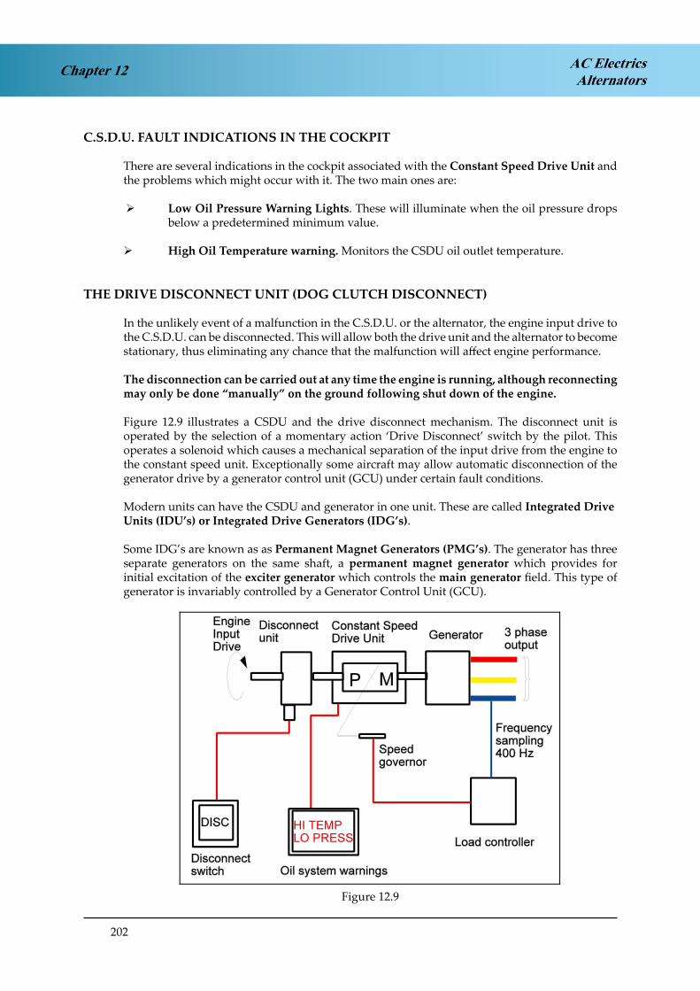
202
Chapter 12 AC ElectricsAlternators
C.S.D.U. FAULT INDICATIONS IN THE COCKPIT
There are several indications in the cockpit associated with the Constant Speed Drive Unit and the problems which might occur with it. The two main ones are:
¾ Low Oil Pressure Warning Lights. These will illuminate when the oil pressure drops below a predetermined minimum value.
¾ High Oil Temperature warning. Monitors the CSDU oil outlet temperature.
THE DRIVE DISCONNECT UNIT (DOG CLUTCH DISCONNECT)
In the unlikely event of a malfunction in the C.S.D.U. or the alternator, the engine input drive to the C.S.D.U. can be disconnected. This will allow both the drive unit and the alternator to become stationary, thus eliminating any chance that the malfunction will affect engine performance.
The disconnection can be carried out at any time the engine is running, although reconnecting may only be done “manually” on the ground following shut down of the engine.
Figure 12.9 illustrates a CSDU and the drive disconnect mechanism. The disconnect unit is operated by the selection of a momentary action ‘Drive Disconnect’ switch by the pilot. This operates a solenoid which causes a mechanical separation of the input drive from the engine to the constant speed unit. Exceptionally some aircraft may allow automatic disconnection of the generator drive by a generator control unit (GCU) under certain fault conditions.
Modern units can have the CSDU and generator in one unit. These are called Integrated DriveUnits (IDU’s) or Integrated Drive Generators (IDG’s).
Some IDG’s are known as as Permanent Magnet Generators (PMG’s). The generator has three separate generators on the same shaft, a permanent magnet generator which provides for initial excitation of the exciter generator which controls the main generator field. This type of generator is invariably controlled by a Generator Control Unit (GCU).
Figure 2.9.Figure 12.9

203
Chapter 12AC ElectricsAlternators
VARIABLE-SPEED CONSTANT FREQUENCY POWER SYSTEMS (VSCF)
A variable speed constant frequency system (VSCF) uses a frequency wild generator driven by the engine and the variable frequency out put is electronically converted into a constant frequency 400 Hz supply. The conversion is achieved by a generator converter control unit(GCCU) which first passes the variable frequency supply through a full wave rectifier where it is rectified and filtered and then to an inverter where it is formed into a 115v/200v/400Hz/3phase supply. This of course eliminates the need for a hydro mechanical CSDU and all its associated controlling mechanisms. This improves reliability and flexibility on the installation as the electronic circuit does not necessarily have to be located in the engine compartment with the generator. VSCF systems are currently fitted to Boeing 737 aircraft and several military aircraft. The VSCF also incorporates a built in test facility which can provide fault isolation information to the ground engineer.
SELF EXCITED GENERATORS
A self excited generator is one which has some permanent magnetism in its exciter generator. On initial rotation, the flux from these Stationary Permanent Magnets causes an induced AC voltage and therefore current to flow in its rotor. The rotor output is then fed directly to a rotating rectifier which in turn supplies the rotating field coils of the main generator with a DC supply.
The output of the main generator stator is tapped to provide a regulated supply to the exciter field so enabling the voltage to be controlled.
LOAD SHARING OR PARALLELING OF CONSTANT FREQUENCY ALTERNATORS
When running two or more constant frequency alternators in parallel they must be controlled in order that each one takes a fair and equal share of the load.This “load sharing” or “paralleling” requires that two parameters are regulated:
¾ Real Load.¾ Reactive Load.
REAL LOAD
Real Load is the actual working load output available for supplying the various electrical services and it is measured in Kilowatts (real power or true power see 1.16).Real Load is directly related to the mechanical power or torque which is being supplied to the alternator drive by its prime mover, i.e. the engine or CSDU.Real Load Sharing is achieved by controlling the Constant Speed Drive Unit (C.S.D.U.) and adjusting the torque at its output shaft so that if the torque of the two or more CSDU’s is equal then the real load taken by each generator is the same.
REACTIVE LOAD
Reactive Load is the so-called Wattless Load which is the vector sum of inductive and capacitive currents and voltages expressed in KVAR (Kilo Volt-Amperes Reactive again see 1.16). Reactive Load Sharing is achieved by controlling the Voltage Output (Exciter Field Current) of each generator that is connected in parallel. If their voltages are identical then the reactive load on each generator will be the same.

204
Chapter 12 AC ElectricsAlternators
PARALLEL CONNECTION
To control the real and reactive load when two or more generators are paralleled there are two separate load sharing circuits, one to detect and control real load and one to detect and control reactive load.N.B. It must be stressed that until a generator is connected in parallel with one or more generators it will not be connected into the load sharing circuits. While constant frequency alternators are operating as individual units, such as at engine start when only one alternator may be on line, their Real Load and Reactive Load sharing circuits are not connected.
BEFORE CONNECTING IN PARALLEL
AC generators, or alternators, are synchronous machines which will lock frequencies when they are operated in parallel. The system frequency thus becomes that of the alternator with the highest load.
However if the two alternators are at different frequencies before they are connected in parallel then damage can occur as one generator tries to slow down and the other tries to speed up, so they must be at the same frequency before paralleling.
As well as being at the same frequency they must also be of the same phase sequence, i.e. at any point in time phase A, B and C on the first generator must be identical to phase A, B and C on the second generator. The Voltage of each generator being paralleled must also be the same.
Figure 2.10 Conditions Required Before ParallellingFigure 12.10 Conditions Required Before Paralleling

205
Chapter 12AC ElectricsAlternators
LAYOUT OF A PARALLELED SYSTEM
Figure 12.11 shows a diagram of the layout of a three generator paralleled system. Notice that for each of the three phases of the output there is a separate bus bar, for example the No1 generator bus bar (Gen Bus1) is made up of three separate bus bars A, B and C for phases A, B and C. The generator is connected to its own bus bar through a 3 phase circuit breaker called the Generator Circuit Breaker (GCB., operated automatically or controlled from the flight deck. All the electrical loads of the aircraft are shared between the three generator bus bars.
To operate the generators in parallel they are connected through their respective generator bus bars to a synchronising bus bar via a Bus Tie Breaker (BTB. A Bus Tie Breaker is a 3 phase circuit breaker controlled automatically or manually from the flight deck.
The synchronising bus bar takes no electrical loads at all, it is only there to allow the engine driven generators to be operated in parallel. Ground power or power from the APU generator can be connected into the synchronising bus and from there can be fed to the load bus bars through the BTB’s when the engine generators are not operating and the GCB’s are open.
Figure 2.11A Three Generator Parallelled SystemFigure 12.11A Three Generator Paralleled System

206
Chapter 12 AC ElectricsAlternators
REAL LOAD SHARING
The Load Controller controls the basic frequency of the AC generator (400Hz).
After paralleling the load controller’s work together to evenly share the real load by increasing the torque input to the lower speeding alternators drive and decreasing the torque input to the higher speeding alternators to ensure each alternator takes an equal share of the load.
Current transformers sense the Real Load distribution at the output of each of the paralleled alternators.
When current flows through these transformers voltage is induced in them and a current will flow in the Load Sharing Loop. Each of the current transformers, which are connected in series with each other in the loop, has an Error Detector wired in parallel with it.
If it is assumed initially in Figure 12.12 that conditions of balanced load have been attained, then the current output of each current transformer can also be assumed to be 5 amperes and no current will flow through the error detectors.
Figure 2.12 Real Load Sharing CircuitFigure 12.12 Real Load Sharing Circuit
Now imagine that the drive unit of the No 1 alternator increases its torque output, it will take a bigger share of the load than the other two alternators which will decrease by a proportional amount.
The output of the Nº 1 alternator current transformer has increased to 6 amperes so this will mean that the output of the No2 and 3 transformers will decrease to 4 amps so that the average current flowing in the circuit is still 5 amperes.
According to Kirchoff’s first law the difference between each current transformer and the average current will be pushed through the error detectors in opposite directions. This signal, when amplified, will be sent to the speed governors to tell the CSDU for the No 1 Gen to reduce torque (speed. and the CSDU’s for the No 2 and 3 Gen to increase torque (speed. until the current in each transformer is once again equal and the real load is once again balanced.
Real load sharing is controlled by matching CSDU speed (torque)

207
Chapter 12AC ElectricsAlternators
REACTIVE LOAD SHARING
The reactive load sharing circuit shown below looks very similar to the real load sharing circuit. It works in a similar fashion but it is a completely separate circuit.
The sensing of out of balance loads by the current transformers is the same but this time the error detector needs to know the difference between the reactive loads carried by each generator. The mutual reactor is a phase shifting transformer which ensures that the error detector only detects that part of the current which is 90° out of phase with the voltage (reactive load.. The error signal is then amplified and correcting signals are sent to the generator field circuit to increase the voltage on the low voltage generator and reduce the voltage of the higher voltage generator to balance the reactive load.
Reactive load sharing is controlled by the Voltage Regulators matching voltage outputs(field excitation).
Figure 2.13 Reactive Load Sharing CircuitFigure 12.13 Reactive Load Sharing Circuit
LOAD SHARING GENERAL
It is typical to run three and four generator systems in parallel but most modern twin engine aircraft with two generators run the generators in isolation (Split Bus System).
In those three and four generator systems the load sharing circuits operate as shown above but are extended to cater for the required number of generators.
If any generator in a parallel system is not connected in parallel then it will not be connected to the load sharing circuits either.
REMEMBER: Real load sharing - speed, frequency, torque (CSDU) Reactive load sharing - excitation current, field current (Voltage Regulator)

208
Chapter 12 AC ElectricsAlternators
ALTERNATOR COOLING
The heat generated in the alternator stator windings due to the current flow through them means that some form of cooling system is required. Those systems with frequency wild generators or constant frequency generators with separate CSDU’s typically use ram air cooling in flight and some means to induce an airflow on the ground.IDG’s or IDU’s use their oil to cool the stators which is then cooled in its own oil cooler.
GENERATOR FAULT PROTECTION
When constant frequency alternators are paralleled, then the requirement for other Control and Protection devices become apparent.There follows a non-exhaustive list of some of those devices:
¾ Bus Tie Breakers (BTB’s)
¾ Discriminatory circuits.
¾ Differential Fault Protection circuits.
¾ Synchronising Units.
¾ Failure Warning systems.
¾ Load meters.
¾ Voltage and Frequency meters.
¾ Generator Control Units (GCU)
BUS TIE BREAKERS (B.T.B.s)
A bus tie breaker connects two bus bars together. In a paralleled system it connects an alternator to the synchronising bus bar. The synchronising bus bar allows two or more alternators to be connected in parallel with each other while the BTB’s are closed. Control of the BTB.can be automatic or manual dependent on the type of aircraft. Correct signals from a Synchronising Unit (monitoring phase frequency and voltage) must be available before the BTB. will close and put the alternator in parallel with another. In a paralleled system the BTB’s are normally closed. In a Split Bus system (non paralleled. the BTB is normally open.
Visual indication of the position of the BTB’s is given by indicators on the electrical control panel or the electronic display panel.
DISCRIMINATORY CIRCUITS
When alternators are paralleled, Discrimination Circuitry is required to ensure that in the event of a fault; only the faulty system is disconnected from the appropriate bus bar. This is achieved by selective switching of the GCB’s and BTB’s.

209
Chapter 12AC ElectricsAlternators
DIFFERENTIAL FAULT PROTECTION
Control and protection devices must be included within the power supply circuits. These will monitor system performance and appropriately operate the relevant circuit breakers,GCB’s BTB’s etc. This may be achieved by a component known as a bus power control unit (BPCU) which monitors the system by current transformers placed at each generator and at each bus bar. It will isolate a defective generator or faulty bus bar and reconfigure the electrical system to maintain the maximum usage.
Protection is provided for:
¾ Over / Under Voltage
¾ Over / Under Frequency
¾ Over / Under Excitation.
¾ Differential Current Faults, (short circuits between bus bars or bus bar to ground, or open circuit faults unbalancing phase outputs).
SYNCHRONISING UNITS
Before the alternator can be connected to a bus bar which is common to another alternator its voltages, frequency and phase sequence must be within very strict limits and in the same order. The Synchronising Unit ensures that these values are within limits before it will allow connection to a common bus bar. There are two methods in use:
¾ Automatic Control
¾ Manual (Dark Lamp) Method
Automatic control will not allow the BTB or GCB to close and parallel the generators until the voltage, frequency and phase sequence of the oncoming generator is within limits. This may be achieved by circuitry within a bus bar protection control unit or in the Generator Control Units (GCU’s) of a modern IDG system..
The Manual (Dark Lamp) method is a much older method but remains in use on a few aircraft.Synchronising Lights on the alternator control panel will show when there are differences between phases of two supplies. Synchronisation is indicated when the lamps are “dark” and then the BTB, or GCB can be closed by means of the manual switch.
GENERATOR FAILURE WARNING LIGHT
A Generator Failure Warning Light will illuminate when its associated GCB is tripped. The Centralised Warning System will operate simultaneously with the Generator Warning Light and in some aircraft Aural Warnings are generated.
Aircraft with electronic systems management display units will show the failure and the associated schematic display.

210
Chapter 12 AC ElectricsAlternators
LOAD METERS
KW / KVAR Meters are used in paralleled alternator systems to indicate the Real Power (KW) or the Reactive Power (KVAR) output. Only one meter may be used to indicate both parameters, selection of a switch will determine which of the two is shown. Typically the switch is selected so that the KW output is normally displayed.
The Real Load is the part of the alternator output which is available to do work at the bus bar. The Reactive Load is the part of the alternator output which is used to create electromagnetic and electrostatic effects in the circuits. It is the so-called Wattless Load which is the vector sum of the Inductive and capacitive Currents and voltages.
Load meters on modern electronic display units may only show a percentage of the maximum power being taken.
VOLTAGE AND FREQUENCY METERS
Voltage and frequency indications are also provided for each generator. Typically only one voltmeter and one frequency meter is provided in systems with several alternators in circuit. The voltage or frequency of any alternator can be selected by a Multi-position Switch. The switch can usually be positioned to show not only the supply frequency and voltage of the engine driven alternators, but also that of the auxiliary power unit, the ground power unit or the Emergency Ram Air Turbine, if provided.
GENERATOR CONTROL UNIT (GCU)
In a modern generator control system a Generator Control Unit (GCU) houses circuitry to provide many functions of power control and protection. A typical GCU will monitor generator output and provide voltage regulation by controlling the exciter field current. Protection circuitry will monitor for over voltage and over current, frequency, phase sequence and differential current protection. A GCU will be provided for each generator and they may work as a team with the BPCU in controlling fault isolation switching.
The GCU may also house an Exciter Control Relay otherwise known as a Generator Control Relay or Generator Field relay. The exciter control relay controls the exciter field current supply to the generator field. In the event of a dangerous fault occurring (over excitation or over voltage) the fault protection circuit will open the exciter control relay which will cause the generator output to fall to a residual value making it safe. The GCU will also open the generator circuit breaker (GCB. to disconnect the generator from its bus bar. (In a paralleled system power would be maintained to the generator bus bar from the other generators through the BTB..
EMERGENCY SUPPLIES
In the unlikely event of some, or the entire engine driven AC power generation systems on the aircraft failing, alternative methods of supply must be made available. Some alternative means of providing AC are listed below -
¾ Ram Air Turbine (R.A.T)¾ Auxiliary Power Unit (A.P.U.)¾ Static Inverter.¾ Hydraulic Motor driven generator.

211
Chapter 12AC ElectricsAlternators
THE RAM AIR TURBINE (R.A.T.)
The Ram Air Turbine (R.A.T. or E.L.R.A.T.), when lowered into the slipstream of an aircraft in flight will produce an emergency source of AC power. The output is controlled at a nominal115v/200v/400Hz/3 phase it will give limited operation only of Flight Instrument and Radio services in the event of Total Alternator Failure. (RAT’s driving an electrical generator have been largely replaced by RAT’s driving a hydraulic pump, as modern aircraft are more dependent on hydraulic power to power the primary flying controls in an emergency)
THE AUXILIARY POWER UNIT (A.P.U)
The Auxiliary Power Unit (A.P.U.) is usually a small gas turbine engine mounted in the aircraft tailcone. This engine runs at a constant speed and has its own protection devices in the event of a Fire, Low Oil Pressure, High Oil Temperature, Overspeed or Overheat.It can be used, among other things, to drive a 115v/200v/400Hz/3 phase alternator for ground servicing supplies, or, in some aircraft, for emergency supplies in the air.The A.P.U. alternator cannot be paralleled with the engine driven alternators, and will only supply power to the bus bars when no other source is feeding them.
THE STATIC INVERTER
A Static Inverter is a Solid State Device capable of supplying the aircraft with 115v/200v/400Hz/3phase for the limited operation of instrument and radio services.It is powered by the aircraft batteries or from an essential DC Bus Bar.
GROUND POWER CONSTANT FREQUENCY SUPPLY SYSTEM
The standard modern Ground Power Unit output is 115v/200v /400Hz/3phase.
When plugged into the aircraft it can be used to supply all the aircraft electrical services.The ground power unit circuitry must include automatic protection systems which will ensure that ground power;-
¾ Cannot be connected to the aircraft distribution system if the system is already being supplied by its own alternators.
¾ Cannot be connected if the phase sequence of the supply is incorrect.
¾ Will be rejected and switched off at source if over voltage occurs.

212
Chapter 12 AC ElectricsAlternators
TYPICAL CONTROLS AND INDICATIONS
Figure 12.14 shows typical controls and indications for a three engine paralleled system. This type of panel uses “switch lights” these are a combination switch and indicator, either having a momentary or alternate action eg push once to activate (Generator disconnect switch) or push once to switch “on”, then push a second time to switch “off” (Galley power on/off). The indicator shows switch position or system status.
Each engine drives a constant frequency generator (Integrated Drive Generator or IDG). Oil temp indications are shown along with overheat and low pressure warning lamps in the disconnect switch. The disconnect switch is guarded to prevent inadvertent operation.
CLOSE TRIPCLOSE TRIPCLOSE TRIPTRIPCLOSE
GEN OIL
CLOSE TRIPCLOSE TRIPCLOSE TRIPCLOSE TRIP
TRIP TRIP CLOSE TRIP
Figure 2.14 Control and Indications for A Three Engine Parallel System
The APU also drives a generator but this one does not need a constant speed unit because the APU runs at a constant speed.
The generator field switch lights control the field excitation circuit (exciter control relay) the “flow bar” in the “close” switch light illuminates to indicate the generator field is complete and the voltage and frequency can be checked by selecting the required generator on the rotary switch and reading off the voltmeter and frequency meter in the upper right corner of the panel. The “trip” switch light opens the field circuit to reduce the generator voltage to zero.
Figure 12.14 Control and Indications for a Three Engine Parallel System

213
Chapter 12AC ElectricsAlternators
The Generator Circuit Breaker (GCB. is controlled by the GCB switch lights (close/trip) which connect or disconnect the generator to its’ own AC bus bar or the APU to the AC Tie Bus. The load on each generator can be monitored by the Real/Reactive load indicator showing KW or KVAR. The meter normally shows KW but KVAR can be shown by pressing and holding the KVAR button to the left of the gauges.
The BTB’s are controlled in the same manner to connect the generator busses to the AC tie bus for parallel operation all three generators are normally connected in parallel to share the total aircraft electrical load.
Each AC bus feeds a TRU which converts 115v/200v/400Hz/3phaseAC to 28v DC to power the individual DC busses these too are normally paralleled through tie breakers which are all controlled by the DC Bus Isolation switch.
The DC part of the system can also be checked for Voltage and Current by use of the other rotary selector and meters for DC Volts and Amps
The Standby bus bars can be fed from the normal electrical supply (AC and DC. or from the battery in the event of a total supply failure. The Red fail lights indicate no voltage on the essential or Standby bus bars.
214
AC ElectricsAlternatorsChapter 12
QUESTIONS
1. An alternator is:
a. a reversing input switch. b. an AC generator.c. a DC generator. d. a static inverter.
2. AC generators usually have a rotating field and a fixed armature to:
a. reduce the overall diameter of the of the generator. b. allow the output to be taken from the stator.c. reduce the weight of the generator. d. prevent arcing at the commutator.
3. The output of an AC generator is taken from:
a. the exciter windings. b. the field coils.c. the stator windings. d. the rotor coils.
4. The moving part of an alternator is:
a. the rotor.b. the megacycle. c. the stator.d. the frequency.
5. A frequency wild alternator must be:
a. paralleled.b. a rotating magnet type. c. self exciting.d. unparalleled.
6. In a 3 phase AC generator circuit, the phase voltage is:
a. greater than line voltage.b. 10% higher than line voltage. c. less than line voltage.d. equal to line voltage.
7. If an alternator output is frequency wild, it would normally be used for:
a. flight instruments. b. charging a battery. c. all AC equipment.d. prop and engine de-icing systems.

215
Chapter 12AC ElectricsAlternators
8. The generator output voltage is increased by:
a. putting more load on it. b. the frequency controller.c. decreasing the generator field voltage. d. increasing the generator field current.
9. A constant frequency AC supply in an aircraft with only frequency wild generators is provided by:
a. an inverter. b. a diode.c. an auto-transformer. d. a rectifier.
10. An alternator normally used to supply an aircrafts power system would be:
a. single phase. b. three phase. c. two phase.d. frequency wild.
11. A permanent magnet in a rotating field generator:
a. provides for initial excitation of the field.b. controls the amount of excitation in the stator windings. c. provides the initial excitation in the voltage regulator.d. can be flashed by the application of alternating current.
12. Voltage control of an alternator output is achieved by varying the:
a. excitation of the rotating commutator. b. load current.c. excitation of the rotating field. d. power factor.
13. Frequency wild AC is produced when:
a. a transformer winding open circuits.b. the voltage regulator is malfunctioning.c. the rotational speed of the generator varies. d. the alternator becomes angry.
14. In a star connected supply system:
a. line and phase current are equal.b. line current is greater than phase current. c. line current is less than phase current.d. phase current is 0.707 times line current.

216
AC ElectricsAlternatorsChapter 12
15. In a 3 phase supply system, line voltage would be sensed between the:
a. phases only.b. phase and earth.c. phase and neutral. d. phases and earth.
16. One advantage of three phase generation over single phase generation is that:
a. most aircraft services require a three phase supply. b. it can be more easily transformed into DCc. it gives more compact generators and allows lower cable weights. d. the power factor is much lower.
17. In a typical aircraft constant frequency supply system, the phase voltage is:
a. 200. b. 115. c. 208. d. 400.
18. An alternator with its output taken from its stationary armature, has:
a. a stationary field.b. its field excitation fed directly to the armature. c. AC excitation.d. a rotating field.
19. The phase voltage in a star wound three phase system is measured between:
a. phase and neutral. b. two phases.c. two lines.d. neutral and earth.
20. If one phase of a star wound three phase system becomes earthed, it will:
a. earth all three phases.b. cause a large current to flow in the neutral. c. have no effect on the other phases.d. cause a reduction in the frequency of the supply.
21. The alternators fitted in an aircrafts main power supply system would normally be:
a. brushed self excited machines. b. frequency wild.c. self excited.d. externally excited.

217
Chapter 12AC ElectricsAlternators
22. A voltage regulator works by:
a. sensing the battery voltage.b. assessing the impedance of the circuit. c. varying the circuit voltage.d. varying the rotating field strength.
23. To ensure correct load sharing on paralleled alternators:
a. both real and reactive loads should be balanced. b. actual loads should be the same.c. reactive loads should be the same.d. the load impedance should be constant.
24. Reactive load sharing is achieved by:
a. altering the loads on the bus bars.b. varying the generator rotational speed. c. varying the generator field current.d. altering the C.S.D.U. output torque.
25. Real load sharing is achieved by:
a. varying the alternator rotational speed. b. varying the generator field current.c. altering the loads on the bus bar. d. the voltage regulator.
26. The phase relationship of paralleled generators should be ;-
a. unimportant. b. 180° apart. c. synchronous. d. 120° apart.
27. In a constant speed parallel operation alternator system:
a. each alternator has its own constant speed drive unit. b. all engines are run at the same speed.c. all alternators are driven by the same engine.d. engine speed is governed by the constant speed drive unit.
28. An aircrafts constant frequency supply is maintained at:
a. between 350 - 450 Hz. b. between 380 - 420 Hz. c. between 115 - 200 Hz. d. between 395 - 495 Hz.

218
AC ElectricsAlternatorsChapter 12
29. For a modern aircraft powered by an AC system, the ground power unit must supply:
a. 28 volts AC only. b. 200 volts.c. 115 volts, three phase.d. 200 volts, three phase, 400 Hz.
30. Oil for the operation of a C.S.D.U. is:
a. supplied from the engine oil system. b. a separate self contained supply.c. drawn from a common tank for all C.S.D.U.s. d. only required for lubrication purposes.
31. Malfunction of a C.S.D.U. requires:
a. automatic electrical disconnection of the drive at any time in flight. b. that the input drive will shear on the ground only.c. operation of the drive disconnect switch at any time in flight. d. operation of the drive disconnect switch on the ground only.
32. Before two constant frequency AC generators can be connected in parallel:
a. their frequency, phase, phase sequence and voltage must match, and a means of automatic real and reactive load sharing must be available.
b. real and reactive loads must match. Frequency, phase and voltage must be within limits.
c. the synchronisation lights on the alternator control panel must be fully bright.d. suitable control arrangements must exist for the sharing of real and reactive loads. these
will correct any phase or frequency error existing at the time of connection.
33. The generator control relay (G.C.R) is:
a. in the excitation circuit.b. between the alternator and its load bus bar. c. in the stator circuit.d. between the load bus bar and the synchronous bus bar.
34. The running excitation current for an alternator is:
a. ACb. DC from the aircraft batteries. c. DC from the static inverter.d. DC which is rectified AC and could be from a separate excitation generator on the main
rotor shaft.
35. If each phase of a three phase star wound system has a phase voltage of 115 volts, the voltage obtained by bridging two phase would be:
a. 200 volts AC b. 173 volts DC c. 28 volts DC d. 173 volts AC

219
Chapter 12AC ElectricsAlternators
36. Protection from ‘earth’ faults and ‘line to line’ faults is given by:
a. a negative earth detector.b. a fault protection system including a differential protection monitor. c. the synchronisation unit.d. reactive load sharing circuits.
37. Warnings of C.S.D.U. oil overheat are given in the cockpit by:
a. audio warning.b. an ‘oil overheat’ warning light.c. a ‘low oil pressure’ warning light. d. a temperature gauge.
38. One disadvantage of parallel operation is that:
a. faults can propagate, and any error in supply can affect all services.b. the system is less flexible due to the need for additional control and protection
circuits. c. the greater load on the C.S.D.U.s means that their power / weight ratio is much
reduced. d. there is a considerable increase in complexity compared with a non-paralleled system,
due to the need for C.S.D.U.s and load sharing circuits.
39. Alternators in parallel operation require the maintenance of constant frequency and phase synchronisation to:
a. balance the battery voltage when more than one battery is being used. b. prevent recirculating currents.c. control their voltage.d. reduce their magnetic fields.
40. The A.P.U. generator can only be used when:
a. another generator is on line. b. the aircraft is on the ground.c. the bus bars are being fed from another source.d. when no other power source is feeding the bus bar.
41. The purpose of the differential protection circuit in a three phase AC system is:
a. to compare alternator output current to bus bar current. b. to compare on and off load currents.c. to compare the alternators reactive load to its real load. d. to compare the C.S.D.U. efficiency ratings.
42. An alternator driven by a C.S.D.U:
a. can never be paralleled.b. will require a voltage controller.c. will require a lubrication system separated from its drive oil system. d. will not require a voltage controller.

220
AC ElectricsAlternatorsChapter 12
43. In the event of a mechanical malfunction of the alternator:
a. the drive disconnect unit will automatically separate the C.S.D.U. from the alternator.b. the real load will be adjusted to compensate.c. the quill drive will fracture.d. the C.S.D.U. oil temperature will decrease.
44. The load meter, upon selection to “KVAR” would indicate:
a. total power available. b. reactive loads.c. active loads.d. only DC resistive loads.
45. Disconnection of the C.S.D.U. in flight would be advisable if:
a. the frequency meter indicated a discrepancy of greater than 5 Hz between alternators. b. there was an over or under voltage.c. the oil temperature was high or the oil pressure was low. d. the engine failed.
46. To increase the real load taken by a paralleled AC generator, the:
a. generator drive torque is increased. b. generator excitation is increased.c. generator drive torque and field excitation are increased.d. generator voltage regulator adjusts the generator rotor torque.
47. Load sharing circuits are necessary whenever:
a. generators are operating in series.b. generators are operating independently.c. the ground power and the A.P.U. are serving the bus bars together. d. generators are operating in parallel.
48. Paralleled alternators will have:
a. one load meter which measures total system load. b. one voltmeter for each alternator.c. one load meter for each alternator.d. one meter which indicates both voltage and frequency.
49. Frequency controlled generators are:
a. always paralleled.b. not always paralleled. c. never paralleled.d. paralleled only when the DC is paralleled.

221
Chapter 12AC ElectricsAlternators
50. If the C.S.D.U. drive disconnect unit had been used, the drive can:
a. only be reconnected when the aircraft is on the ground.b. be reinstated in flight from the electrical supply department. c. be reinstated in flight from the flight deck.d. be reinstated when necessary by using the Ram Air Turbine.
51. When selected to ‘kW’, the alternator load meter will indicate the:
a. total circuit load. b. real load.c. reactive load.d. current flowing in the field.
52. An AC generator’s I.D.U. oil system:
a. is self contained.b. is common with the engine oil system. c. is used only for cooling.d. is used only for lubrication.
53. An alternator driven by a non-integrated constant speed drive unit, has windings that are cooled by:
a. water. b. oil.c. oil and water. d. air and/or oil.
54. The load in a paralleled AC system is measured in:
a. KW & KVA. b. KW & KV. c. KV & KVAR. d. KW & KVAR.
55. Paralleled generators must share real and reactive loads:
a. to prevent large current flows through the T.R.U.s.b. to prevent out of balance forces being fed through the C.S.D.U.s to the engines. c. to prevent large flows of current from one generator to another.d. to prevent harmonic frequencies being created in the synchronous bus bars.
56. One advantage of running alternators in parallel is that:
a. the supply to all circuits is in phase.b. a large capacity is available to absorb heavy transient loads when switching of heavy
currents occurs.c. the risk of overloading the system is reduced. d. there is only a requirement for one C.S.D.U.

222
AC ElectricsAlternatorsChapter 12
57. When an external AC supply is feeding the bus bars:
a. the internal bus bars are disconnected.b. the aircraft generators are run in parallel with the external supply. c. the aircraft generators are taken off line.d. the synchronising unit will ensure that no frequency difference exists between the
aircraft generators and the external supply.
58. A three phase AC system can be used to supply:
a. both one or three phase equipment. b. only three phase equipment.c. only single phase equipment.d. only inductive or capacitive loads.
59. In a frequency wild generation system:
a. generators can be run in parallel only when all engine r.p.m.s match.b. generators can never be run in parallel and there can be no duplication of supply.c. generators can never be run in parallel, but after rectification, the D,C, can be fed to a
common bus bar to provide a redundancy of supply.d. capacitive and inductive loads can be fed with no problems of overheating.
60. A fault on one phase of a three phase AC star connected system would:
a. have no effect.b. effect only the phase concerned. c. cause inductive loads to overheat. d. affect all three phases.
61. The purpose of an inverter is:
a. to change AC into DCb. to change the frequency of the AC supply. c. to act as a back up for the alternator.d. to change DC into AC
62. A low reactive load on one generator is compensated for by:
a. altering the excitation current flowing in its field circuit. b. increasing the rotor speed.c. increasing the real load on the other generators. d. overall load reduction.
63. In the event of a mechanical failure occurring in the generator, the C.S.D.U. is protected by:
a. a hydraulic clutch. b. a universal joint. c. a quill drive.d. a feather drive.

223
Chapter 12AC ElectricsAlternators
64. To increase the real load which is being taken by a paralleled alternator:
a. the voltage regulator adjusts the generator rotor torque. b. both its drive torque and its excitation are increased.c. only its excitation is increased. d. its drive torque is increased.
65. An earth fault on a bus bar of a parallel generator system:
a. would require that the appropriate G.C.B. should open. b. would require that the appropriate B.T.B. should open.c. would require that both the appropriate G.C.B. and B.T.B. should open. d. would require that all alternators should operate independently.
66. To prevent high circulating currents between paralleled alternators, the following conditions should be met:
a. their voltage and frequency must be the same.b. their frequencies must be identical and their phase sequence must be the same. c. their voltage, frequency, phase and phase sequence must all be the same.d. their inductive and capacitive reactances must match exactly.

224
AC ElectricsAlternatorsChapter 12
ANSWERS
1 B 21 A 41 A 61 D
2 B 22 D 42 B 62 A
3 A 23 A 43 C 63 C
4 A 24 C 44 B 64 D
5 D 25 A 45 A 65 C
6 C 26 C 46 A 66 C
7 D 27 A 47 D
8 D 28 B 48 C
9 A 29 D 49 B
10 B 30 B 50 A
11 A 31 C 51 B
12 C 32 A 52 A
13 C 33 A 53 D
14 A 34 D 54 D
15 A 35 A 55 C
16 C 36 B 56 B
17 B 37 D 57 C
18 D 38 D 58 A
19 A 39 B 59 C
20 B 40 D 60 D

225
Chapter 13AC ElectricsPractical Aircraft Systems
CHAPTER THIRTEEN
PRACTICAL AIRCRAFT SYSTEMS
Contents
POWER DISTRIBUTION . . . . . . . . . . . . . . . . . . . . . . . . . . . . . . . . . . .227
THE SPLIT BUS SYSTEM . . . . . . . . . . . . . . . . . . . . . . . . . . . . . . . . . . .227
PARALLEL BUSBAR SYSTEM . . . . . . . . . . . . . . . . . . . . . . . . . . . . . . . .230
QUESTIONS . . . . . . . . . . . . . . . . . . . . . . . . . . . . . . . . . . . . . . . . . .232
ANSWERS . . . . . . . . . . . . . . . . . . . . . . . . . . . . . . . . . . . . . . . . . . .234

226
Chapter 13 AC ElectricsPractical Aircraft Systems
Figure 13.1 Generator Feeder Lines
Flight deck CB
panelLine C
urrentTransform
ers
Engine/W
ingD
isconnect
CS
D G
enerator 2
From A
PU
Generator
To loadB
usbars
Generator
Breaker 1
Generator
Breaker 2
AP
U G
eneratorB
reaker
CS
D G
enerator 1
Engine/W
ingD
isconnect

227
Chapter 13AC ElectricsPractical Aircraft Systems
POWER DISTRIBUTION
In a very basic form, Figure 13.1 shows the general layout of an electrical distribution system for a twin jet aircraft. One generator is driven by and mounted on each engine and one generator is mounted on the APU (not shown). The feeder cables from each generator are routed through the aircraft wings and fuselage to meet at a central distribution compartment usually beneath the flight deck or cabin floor. This distribution compartment will house many of the components already described: GCB’s, BTB’s GCU’s or Voltage regulators, current transformers, main bus bars and bus bar protection circuitry, battery and battery charger. Bus bars and bus bar extensions may be found on the flight deck behind the rear, side and overhead circuit breaker panels.A schematic diagram for this type of system is shown at Figure 13.2
THE SPLIT BUS SYSTEM
The Split Bus Bar System uses 115v/200v/ 400Hz 3 phase constant frequency alternators as the primary power source. They are not designed to run in parallel and therefore do not require complex paralleling and load sharing circuits. A 28v DC supply is provided by two Transformer Rectifier Units (T.R.U.s) convert 115v AC to 28v DC from the two separate AC bus bars. A battery is provided which will provide power to start the APU and limited emergency power to the essential bus bars, or to supply air and electrics on the ground when the engine driven generators are off line.
If, in the circuit shown in Figure 13.2, either alternator should fail, then the main bus bars are automatically connected by the Bus Tie Breaker and they will now serve as one bus bar. Power supplies to all the bus bars are thereby maintained. The APU may then be started in flight and its generator can be used to restore full power by connecting to AC bus 1 or bus 2. While each alternator separately supplies its own AC non-essential services and the associated T.R.U., the essential AC loads are supplied from only the No 1 main bus bar via a changeover relay. In particular, note that the main AC bus bars are normally isolated from one another, i.e. the alternators are not paralleled
If both alternators should fail, then the AC non-essential services, which are normally supplied from the main AC bus bars, are isolated.
The changeover relay between the No 1 main bus bar and the essential AC bus bar will automatically switch over. This causes the essential AC bus bar to be connected to an Emergency Static Inverter, which should, if the batteries are in a fully charged state, supply the essential AC bus bars for 30 minutes.

228
Chapter 13 AC ElectricsPractical Aircraft Systems
Figure 3.2 Split Bus SystemFigure 13.2 Split Bus System
Under normal conditions, the DC supply in Figure 13.2 is obtained from the two independentT.R.U’s. and the batteries.
The No 1 T.R.U. supplies essential DC loads and the No 2 T.R.U. supplies non-essential DCLoads.
In normal operation the two bus bars supplying the essential and non-essential DC loads are connected together by the Isolation Relay. The batteries are connected directly to the Battery Bus Bar, and through the Battery Relay they will feed the essential DC bus bar.
If one alternator fails then both T.R.U.,s are still supplied through the now closed contacts of the bus-tie breaker, and will still supply all of the DC consumers.
If however both alternators fail, the DC Isolation Relay will open and separate the essential and non-essential bus bars.
Non-essential loads will now no longer be powered, but the AC and DC essential loads will be fed from the battery bus bar, (the AC loads from the static inverter).
External power or supplies from the A.P.U. can be used to feed all electrical services in the aircraft on the ground, but the APU generator may only be capable of supplying one bus bar in flight.

229
Chapter 13AC ElectricsPractical Aircraft Systems
Figure 3.3 A320 Split Bus Control PanelFigure 13.3 A320 Split Bus Control Panel
Figure 3.4m A320 ECAM DisplayFigure 13.4 A320 ECAM Display

230
Chapter 13 AC ElectricsPractical Aircraft Systems
PARALLEL BUSBAR SYSTEM
Figure 13.5 illustrates a four generator paralleled system. This system allows various combinations of alternator operation. Operation of the system begins with the excitation of the alternator field which will bring its output within the limits required before operation of the G.C.B. can occur.
When the G.C.B. closes it connects its associated alternator to its Load Bus Bar. Once the G.C.B. has closed it will remain closed during all normal circuit functioning.
The Bus Tie Breakers are normally closed so that the closure of the G.C.B. effectively connects the alternator to the Synchronising Bus Bar. If the other one of a pair of alternators (1 & 2) or (3 & 4) now comes “on line” it too will be joined in parallel to the synchronising bus bar, but only once the voltage, frequency and phase sequence have been satisfied allowing its GCB to close.
In the system described there are two synchronising bus bars which can be combined or isolated by the Split System Breaker (S.S.B.) depending on the flight phase or other system requirement. Keeping the synchronising bus bars isolated from each other will allow the alternators to operate as two paralleled pairs which would be a requirement for example during an dual autopilot autoland to enable the two autopilots to have totally separate power supplies.
If a single alternator failure occurs with a system similar to that shown in Figure 13.5, then opening of the associated G.C.B. will allow its paired alternator to feed the loads of both of them. However, this would place a larger load upon that alternator than is being carried by the pair on the other synchronising bus bar.
Closure of the S.S.B. would bring all three alternators into parallel operation, thus sharing the total aircraft load between them. Failures are not always that simple however, if there was an earth fault on a load bus bar for instance, opening of the associated G.C.B. would do little to help, the other alternator/s would now be attempting to feed the earth fault. Operation of the B.T.B. associated with the faulty bus bar would prevent the serviceable alternators being affected by the fault, and then the earth fault could be totally isolated by opening the G.C.B. of the alternator feeding it.
Figure 3.5 Parallel Alternator OperationFigure 13.5 Parallel Alternator Operation

231
Chapter 13AC ElectricsPractical Aircraft Systems
An example of an aircraft with this type of paralleled system is the Boeing 747 - 400. Shown below in Figures 13.6.and 13.7 are the control panel and the EICAS display for the electrical system.
Figure 3.6 747 - 400 Electrical Control PanelFigure 13.6 747 - 400 Electrical Control Panel
Figure 3.7 747 - 400 EICAS Electrical DisplayFigure 13.7 747 - 400 EICAS Electrical Display

232
AC ElectricsPractical Aircraft SystemsChapter 13
QUESTIONS
1. The purpose of a synchronising bus bar is to:
a. enable interconnections to be made between generator bus bars. b. supply essential services.c. monitor on-load currents. d. interconnect DC bus bars.
2. Fuses and circuit breakers are fitted:
a. in DC circuits only.b. in both AC and DC circuits. c. in AC circuits only.d. only to protect the wiring.
3. Where the aircraft’s main electrical supply is A.C, DC requirements are met by:
a. batteries. b. T.R.U.s. c. inverters.d. a static inverter.
4. In a split bus system using non-paralleled constant frequency alternators as the primary power source:
a. essential AC loads are supplied directly from Nº 1 AC bus bar. b. essential AC loads are supplied directly from Nº 2 AC bus bar. c. only non-essential AC loads are supplied from the AC bus bars.d. essential AC loads are normally supplied from Nº 1 AC bus bar via the changeover
relay.
5. In a split bus system using non-paralleled constant frequency alternators as the primary power source, if both alternators fail:
a. all non-essential services are lost.b. all non- essential services will be supplied direct from the battery bus bar. c. all non-essential services will be supplied from the static inverter.d. essential DC consumers only will be supplied from the Nº1 T.R.U., all other DC services
will be lost.
6. In normal operation, the split bus bar AC system takes its DC supply from:
a. two T.R.U.s which are always isolated.b. a battery which is supplied from Nº 1 T.R.U. only.c. two T.R.U.s which are connected together by the isolation relay. d. the static inverter.
7. The static inverter in the split bus system supplies:
a. the essential DC consumers. b. the essential AC consumers.c. both essential and non-essential consumers. d. the batteries.

233
Chapter 13AC ElectricsPractical Aircraft Systems
8. In the split bus system, the AC bus bars:
a. are automatically connected via the isolation relay if one alternator fails. b. are automatically connected via the bus tie breaker if one alternator fails. c. can be connected together by switch selection if one alternator fails.d. can never be connected together because there is no load sharing circuit.
9. With parallel generator operation:
a. there are two synchronising bus bars which are normally kept isolated. b. the G.C.B.s connect the generators to the synchronising bus bar.c. the B.T.B.s connect the synchronising bus bars together. d. the G.C.R.s connect the generators to their load bus bars.
10. In a parallel alternator operation, should one alternator fail, then:
a. the other alternators can be selected to supply its load. b. the failed alternators loads will not be supplied.c. the G.C.B. of the failed alternator will remain closed to allow its loads to be supplied by
the remaining alternators.d. the S.S.B. will close allowing the three remaining alternators to share all of the load.
11. If external power is plugged into an aircraft which utilises the split bus system of power distribution, then:
a. it will automatically parallel itself with any alternators already on line. b. it will only supply non-essential AC consumers.c. it will supply all the aircraft services.d. essential AC consumers will be supplied from the static inverter.

234
AC ElectricsPractical Aircraft SystemsChapter 13
ANSWERS
1 A
2 B
3 B
4 D
5 A
6 C
7 B
8 B
9 A
10 D
11 C

235
Chapter 14AC ElectricsTransformers
CHAPTER FOURTEEN
TRANSFORMERS
Contents
TRANSFORMERS . . . . . . . . . . . . . . . . . . . . . . . . . . . . . . . . . . . . . . .237
TRANSFORMATION RATIO . . . . . . . . . . . . . . . . . . . . . . . . . . . . . . . . .237
POWER IN A TRANSFORMER . . . . . . . . . . . . . . . . . . . . . . . . . . . . . . .238
THREE PHASE TRANSFORMERS. . . . . . . . . . . . . . . . . . . . . . . . . . . . . .238
AUTO TRANSFORMERS . . . . . . . . . . . . . . . . . . . . . . . . . . . . . . . . . . .238
RECTIFICATION OF ALTERNATING CURRENT . . . . . . . . . . . . . . . . . . . . .239
HALF WAVE RECTIFICATION . . . . . . . . . . . . . . . . . . . . . . . . . . . . . . .239
FULL WAVE RECTIFICATION . . . . . . . . . . . . . . . . . . . . . . . . . . . . . . . .240
THREE PHASE RECTIFIERS . . . . . . . . . . . . . . . . . . . . . . . . . . . . . . . . .240
TRANSFORMER RECTIFIER UNITS (TRU’s) . . . . . . . . . . . . . . . . . . . . . . .242
INVERTERS. . . . . . . . . . . . . . . . . . . . . . . . . . . . . . . . . . . . . . . . . . .242
QUESTIONS . . . . . . . . . . . . . . . . . . . . . . . . . . . . . . . . . . . . . . . . . .243
ANSWERS . . . . . . . . . . . . . . . . . . . . . . . . . . . . . . . . . . . . . . . . . . .244

236
Chapter 14 AC ElectricsTransformers

237
Chapter 14AC ElectricsTransformers
TRANSFORMERS
One of the biggest advantages that an AC supply has over a DC supply is the ease with which the value of alternating voltage can be raised or lowered with extreme efficiency by the use of Transformers.
A simple transformer would consist of two electrically separate coils wound over iron laminations to form a common core. This forms a completely closed magnetic circuit. See Figure 14.1.
The Primary winding is connected to the AC supply and the output is taken from the Secondary winding.
The alternating voltage and current in the primary winding creates an alternating flux which links across to the secondary winding.
The alternating flux in the secondary winding sets up an e.m.f. of mutual inductance which is available as the output voltage. The output voltage will be 180° out of phase with the input voltage. If a load is placed across the terminals of the secondary winding then a current will flow in the circuit.
Figure 4.1 A Simple TransformerFigure 14.1 A Simple Transformer
TRANSFORMATION RATIO
The Transformation Ratio of a transformer is the ratio of the number of turns of wire on the secondary winding (N2) to the number of turns of wire on the primary winding (N1). The transformation ratio will also allow the determination of input and output voltages by using the formula:
TRANSFORMATION RATIO (r) = N2 = E2N1 E1
If the transformation ratio is greater than one, then the transformer is a Step Up transformer. If the ratio is less than one, then the transformer is a Step Down transformer. See Figure 14.2.
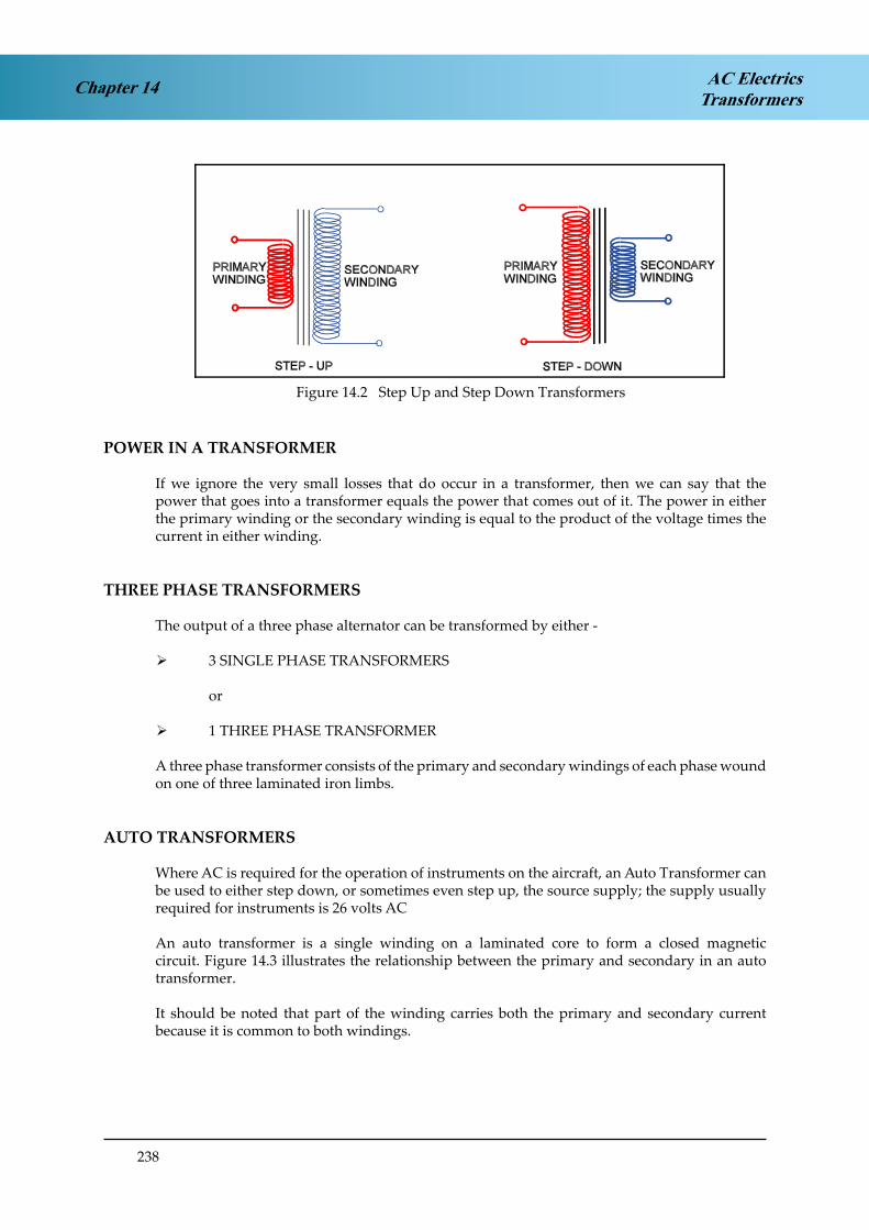
238
Chapter 14 AC ElectricsTransformers
Figure 4.2 Step Up and Step Down TransformersFigure 14.2 Step Up and Step Down Transformers
POWER IN A TRANSFORMER
If we ignore the very small losses that do occur in a transformer, then we can say that the power that goes into a transformer equals the power that comes out of it. The power in either the primary winding or the secondary winding is equal to the product of the voltage times the current in either winding.
THREE PHASE TRANSFORMERS
The output of a three phase alternator can be transformed by either -
¾ 3 SINGLE PHASE TRANSFORMERS
or
¾ 1 THREE PHASE TRANSFORMER
A three phase transformer consists of the primary and secondary windings of each phase wound on one of three laminated iron limbs.
AUTO TRANSFORMERS
Where AC is required for the operation of instruments on the aircraft, an Auto Transformer can be used to either step down, or sometimes even step up, the source supply; the supply usually required for instruments is 26 volts AC
An auto transformer is a single winding on a laminated core to form a closed magnetic circuit. Figure 14.3 illustrates the relationship between the primary and secondary in an auto transformer.
It should be noted that part of the winding carries both the primary and secondary current because it is common to both windings.

239
Chapter 14AC ElectricsTransformers
Figure 4.3 Auto TransformersFigure 14.3 Auto Transformers
Auto transformers are less expensive than two coil transformers because they use less wire, however, they do not electrically isolate the primary and secondary windings and so cannot be used in many circuits for this reason.
RECTIFICATION OF ALTERNATING CURRENT
A Rectifier is a device which will convert Alternating Current (AC. into Direct Current (DC. The operation of the Diode Rectifier is described in the Semiconductor chapter in the Instrument book, and is a very common device in modern aircraft solid state circuits. It can be used to convert AC to DC or as a “Blocking Diode” (electrical non return valve) to prevent reverse current flow in a DC system. Some rectifiers are designed to conduct at a pre determined voltage; these rectifiers are called Zener Diodes.
A diode has a high resistance in one direction and a low resistance in the other. The accepted symbol for a diode rectifier and the direction of conventional current flow is shown in Figure 14.4.
HALF WAVE RECTIFICATION
A diode inserted in the secondary circuit of a transformer will allow current to flow through the load in one direction only. This is termed Half Wave Rectification. The bottom half of the AC waveform is blocked and the frequency of the output is the same as the input, as shown in Figure 14.4.
Figure 4.4 Single Phase, Half Wave RectificationFigure 14.4 Single Phase Half Wave Rectification

240
Chapter 14 AC ElectricsTransformers
FULL WAVE RECTIFICATION
To fill in the gaps between pulses that have been left from half wave rectification a Bridge Rectifier can be used. As can be seen from Figure 14.5 when one half of the bridge circuit is presenting a high resistance to current flow, the other half is allowing it to flow relatively easily. This arrangement is specifically designed to allow the output of the bridge to be of a single polarity. The output can be smoothed to some extent by the addition of a capacitor placed across it
Figure 4.5 Single Phase Full Wave RectifierFigure 14.5 Single Phase Full Wave Rectifier
THREE PHASE RECTIFIERS
The rectification of a three phase supply can be effected by using a formation of six rectifiers in a bridge circuit.
This is shown in Figure 14.6. The output of a Three Phase Rectifier is essentially a steady output.

241
Chapter 14AC ElectricsTransformers
PHASE A PHASE B PHASE C+
-
+-
A
B
C
LINE VOLTAGE BETWEEN PHASES A AND B
DC OUTPUT
+-
A
B
C
LINE VOLTAGE BETWEEN PHASES BAND C
+-
A
B
C
LINE VOLTAGE BETWEEN PHASES A AND C
DC OUTPUT
Figure 4.6 Three Phase Full Wave RectifierFigure 14.6 Three Phase Full Wave Rectifier

242
Chapter 14 AC ElectricsTransformers
TRANSFORMER RECTIFIER UNITS (TRU’s)
TRU’s convert AC at one voltage to DC at another voltage by combining the transformer and rectifier in one unit (usually 115v/200v/400Hz/3phase to 28v DC. to supply the DC needs of an AC distribution system.
TRU’s are invariably multi phase units to achieve a smooth DC output. Indications of TRU output (amps) can be shown on the main electrical panel on the flight deck.
Cooling is achieved by drawing air through the unit which may be monitored for temperature with an overheat warning supplied.
INVERTERS
An inverter converts DC to AC.
The inverter in a constant frequency AC equipped aircraft is used as a source of emergency supply if the AC generators fail, then the inverter is powered by the battery.
Inverters are usually “solid state” static inverters, transistorised in modern aircraft, providing constant frequency AC for operation of flight instruments and other essential AC consumers. Rotary and Static inverters are described in the DC section and are not generally used in modern aircraft.
Aircraft which have a frequency wild distribution system (British Aerospace ATP, ATR 42) use inverters to supply their normal constant frequency requirements. This is done by changing the frequency wild into DC, and then supplies the DC to the inverter (static. to give a controlled AC output.
Inverter output can be monitored for voltage and frequency in the same manner as the main generators.
Cooling is accomplished in the same manner as the TRU.

243
Chapter 14AC ElectricsTransformers
QUESTIONS
1. Instrument transformers normally:
a. Convert 14 volts DC to 26 volts ACb. Reduce the A.C supply to 26 volts for some instruments. c. Change 115 volts to 200 volts for engine instruments.d. Convert 28 volts DC to 28 volts AC
1. An auto-transformer:
a. varies its turns ratio automatically to maintain a constant output voltage with varying input voltage.
b. has only one coil which is used as both primary and secondary.c. will maintain a constant output frequency with a varying supply frequency. d. requires an inductive supply.
2. A step-up transformer is one in which the number of turns on the secondary winding is:
a. the same as the primary if the cable diameter is the same. b. greater than that on the primary.c. less than on the primary.d. always the same as on the primary.
3. A transformer which halves the voltage will have:
a. twice as many turns on the secondary as on the primary. b. half as many turns on the secondary as on the primary.c. half as much current flowing in the secondary as in the primary. d. four times as many turns on the secondary as on the primary.
4. The power output of a transformer is:
a. in proportion to the transformation ratio.b. in inverse proportion to the transformation ratio. c. the same as the power input.d. increased in a step up transformer.
5. With no load across the output terminals of a transformer:
a. the current flow will be maximum. b. the current flow will be negligible.c. the current will be in phase with the voltage.d. the voltage in the primary will be always greater than the secondary.
6. If the voltage induced in the secondary windings is greater than that in the primary then the transformer is:
a. an autotransformer. b. a step up.c. a step down.d. a magnetic amplifier.

244
AC ElectricsTransformersChapter 14
ANSWERS
1 B
2 B
3 B
4 C
5 B
6 B

245
Chapter 15AC ElectricsAC Motors
CHAPTER FIFTEEN
AC MOTORS
Contents
ALTERNATING CURRENT MOTORS . . . . . . . . . . . . . . . . . . . . . . . . . . .247
THE PRINCIPLE OF OPERATION OF AC MOTORS . . . . . . . . . . . . . . . . . . .247
THE SYNCHRONOUS MOTOR . . . . . . . . . . . . . . . . . . . . . . . . . . . . . . .247
THE INDUCTION MOTOR. . . . . . . . . . . . . . . . . . . . . . . . . . . . . . . . . .249
THE SQUIRREL CAGE ROTOR . . . . . . . . . . . . . . . . . . . . . . . . . . . . . . .249
THE INDUCTION MOTOR STATOR . . . . . . . . . . . . . . . . . . . . . . . . . . . .249
SLIP SPEED . . . . . . . . . . . . . . . . . . . . . . . . . . . . . . . . . . . . . . . . . . .250
STARTING SINGLE PHASE INDUCTION MOTORS . . . . . . . . . . . . . . . . . . .250
FAULT OPERATION . . . . . . . . . . . . . . . . . . . . . . . . . . . . . . . . . . . . .250
QUESTIONS . . . . . . . . . . . . . . . . . . . . . . . . . . . . . . . . . . . . . . . . . .251
ANSWERS . . . . . . . . . . . . . . . . . . . . . . . . . . . . . . . . . . . . . . . . . . .254

246
Chapter 15 AC ElectricsAC Motors

247
Chapter 15AC ElectricsAC Motors
ALTERNATING CURRENT MOTORS
Alternating current motors can, in most cases, duplicate the operation of DC motors and are less troublesome to operate. DC motors have a great deal of trouble with their commutation, high altitude flight causing particular difficulty because of the associated arcing that occurs.
The brush equipment is another weak link, the heat generated at the brushes causing them to stick in the holders and as a consequence the resistance between them and the commutator increases, often to the point of becoming an open circuit, when the motor will stop.
Synchronous AC motors do in fact use brush gear, their rotors are fed by relatively low currentDC through slip rings but these in general are less troublesome.
Alternating current motors are particularly suited for constant speed applications since their speed is determined by the frequency of the applied power supply.
Alternating current motors can be operated from either single or multi-phase power supplies.
THE PRINCIPLE OF OPERATION OF AC MOTORS
Whether the AC motor is single or multi-phase, the principle of operation is the same, alternating current applied to the motor stator generates a rotating magnetic field which causes the rotor to turn.
The majority of motors used in aircraft can be divided into two types:
¾ Synchronous Motors. These are basically alternators operated as motors. Alternating current is applied to the stator but the rotor has a Direct Current power source.
¾ Induction Motors. This type has alternating current applied to the stator but the rotor has no power source.
THE SYNCHRONOUS MOTOR
The synchronous motor gets its name because the rotation of the rotor is synchronised with the rotating field set up in the stator. Its construction is basically the same as the rotating field alternator.
As illustrated in Figure 15.1, the application of a three phase supply to the stator causes a rotating magnetic field to be set up around the rotor. If a bar magnet was suspended in the field it would rotate synchronously with it (at the same speed as the rotating field.
In the same way, the rotor of a synchronous motor, which is energised with DC, acts like a magnet. It lines up with the field created by the stator and if the field turns, the rotor turns with it.

248
Chapter 15 AC ElectricsAC Motors
Figure 5.1 Generation of A Rotating Magnetic FieldFigure 15.1 Generation of a Rotating Magnetic Field
Synchronous motors are in fact single speed motors, the speed of rotation depending upon the frequency of the supply. Since in most cases the supply frequency is constant, then so is the motor speed. A synchronous motor will rotate at the same speed as the alternator that is supplying it providing it has the same number of poles, ie if a synchronous motor with 4 poles is supplied with a constant frequency 400 Hz supply it will rotate at a constant 12,000 rpm.
One disadvantage of the synchronous motor is that it is not self starting. To obtain the initial rotation some induction windings have to be added to the rotor to assist in bringing it up to synchronous speed.
Synchronous motors are used on aircraft to indicate engine rpm. A small three phase alternator (tacho-generator) is driven by the engine so that the frequency of the supply will be directly proportional to engine speed. The electrical output is connected to a synchronous motor in the rpm indicator. The indicator needle is coupled to the synchronous motor via a permanent magnet and a ‘drag cup’. As the synchronous motor rotates it ‘drags’ the drag cup around with it, the faster the motor goes the further the drag cup moves and the further around the scale the needle moves. So the movement of the needle will be in proportion to engine rpm.

249
Chapter 15AC ElectricsAC Motors
THE INDUCTION MOTOR
The induction motor gets its name from the fact that an alternating current is induced in the rotor by the rotating magnetic field in the stator.
It is the most commonly used because of its simplicity, its robustness and because it is relatively cheap to produce.
This relative cheapness is mainly because of the fact that the rotor is a self contained unit and not connected to the supply.
Figure 5.2 Squirrel Cage Induction MotorFigure 15.2 Squirrel Cage Induction Motor
THE SQUIRREL CAGE ROTOR
The rotor consists of a cylindrical laminated iron core which has a number of longitudinal bars of copper evenly spaced around the circumference. These bars are joined at either end by rings of the same material to form a composite structure called a Squirrel Cage. The rotor bars are of very low resistance material so that a large current can flow through them.
THE INDUCTION MOTOR STATOR
The stator consists of windings, the number of which is related to the number of poles and also to the number of phases of the power supply. The rotating magnetic field produce in the stator cuts through the bars of the rotor which is basically a closed circuit of low resistance.
The resultant induced voltage creates a relatively large current flow in the squirrel cage. This current flow sets up its own magnetic field which interacts with the rotating field of the stator to produce a torque. If a three phase motor has two phases of its supply reversed, then its direction of rotation will be reversed also.
250
Chapter 15 AC ElectricsAC Motors
SLIP SPEED
The speed of the motor is determined by the frequency of the supply and the load on the motor. The rotor never quite reaches true synchronous speed, if it did then the squirrel cage bars would not be cut by any lines of force and thus would not produce the induced voltage. The difference between synchronous speed and rotor speed is called the slip speed or rotor slip. A typical value of slip would be 5%. Because of the difference in speed between the stator field and rotor the induction motor is sometimes referred to as being asynchronous.
STARTING SINGLE PHASE INDUCTION MOTORS
Single phase induction motors are not self starting. Different methods are used to assist in making them self starting. The most common method is the use of what is called a Split Phase Winding.
If the current in the split phase winding can be made to lead or lag the current in the main winding by 90° then a rotating field can be produced.
The lead or lag can be produced by the following methods -
Resistance starting ¾
Inductance starting ¾
Resistance / inductance starting ¾
Capacitance starting ¾
The application of each method depends on the power output of the motor, e.g. capacitance started motors are usually of less than 2 H.P. output.
FAULT OPERATION
Occasionally the failure of one phase of the supply to a three phase induction motor does happen. If the motor is lightly loaded then it will probably continue to run at about half of its normal speed. This will create a humming noise in the motor which, because of the usually remote locations in which the motors are mounted, will probably not make itself apparent. The fault usually becomes apparent the next time an attempt is made to run the motor, it will not start.

251
Chapter 15AC ElectricsAC Motors
QUESTIONS
1. Synchronous motors are usually supplied by:
a. three phase AC b. single phase AC c. DC to the stator.d. DC to the stator and AC to the rotor.
2. Reversing two phases to a three phase motor will:
a. blow the phase fuses.b. cause the motor to run in reverse. c. overheat the stator windings.d. stall the motor.
3. A synchronous motor runs at a speed that depends upon the supply:
a. voltage. b. current.c. reactance. d. frequency.
4. If one phase of the supply to a three phase motor fails, then:
a. the motor will continue to run at the same speed. b. will slow down and stop.c. will stop immediately.d. will run at about half speed but will not start on its next selection.
5. The basic principle of operation of a 3 phase induction motor is:
a. A rotating field created in the rotor. b. A rotating field created in the stator.c. A stationary field created in the stator. d. A stationary field created in the rotor.
6. In an induction motor:
a. the rotor is star connected.b. magnetic fields blend evenly with one another. c. AC is induced in the rotor.d. a DC supply produces DC in the rotor.
7. In a synchronous motor, the rotor is:
a. energised by DC and it lines up with the magnetic field in the stator. b. wave wound.c. both AC and DC energised.d. impeded by the AC induced into it.

252
AC ElectricsAC MotorsChapter 15
8. An induction motor has:
a. slip rings and brushes. b. a commutator.c. no slip ring or brushes.d. slip rings but no brushes.
9. A squirrel cage rotor:
a. is not connected to the supply. b. is expensive to produce.c. rotates at exactly synchronous speed. d. is a closed circuit of high resistance.
10. A starting circuit for a powerful single phase induction motor might be:
a. a capacitance starter.b. a resistance / inductance starter. c. a cartridge starter.d. a bump starter.

253
Chapter 15AC ElectricsAC Motors

254
AC ElectricsAC MotorsChapter 15
ANSWERS
1 A
2 B
3 D
4 D
5 B
6 C
7 A
8 D
9 A
10 B

255
Chapter 16AC ElectricsBasic Computers
CHAPTER SIXTEEN
BASIC COMPUTERS
Contents
COMPUTERS . . . . . . . . . . . . . . . . . . . . . . . . . . . . . . . . . . . . . . . . . .257
ANALOGUE COMPUTERS . . . . . . . . . . . . . . . . . . . . . . . . . . . . . . . . .257
DIGITAL COMPUTERS . . . . . . . . . . . . . . . . . . . . . . . . . . . . . . . . . . . .257
BINARY NUMBER SYSTEM . . . . . . . . . . . . . . . . . . . . . . . . . . . . . . . . .258
CONVERTING DECIMAL NUMBERS TO BINARY NUMBERS: . . . . . . . . . . . .259
OCTAL NOTATION SYSTEM . . . . . . . . . . . . . . . . . . . . . . . . . . . . . . . .262
HEXADECIMAL NUMBER SYSTEM . . . . . . . . . . . . . . . . . . . . . . . . . . . .263
DIGITAL COMPUTER COMPONENTS. . . . . . . . . . . . . . . . . . . . . . . . . . .264
CENTRAL PROCESSING UNIT (CPU) . . . . . . . . . . . . . . . . . . . . . . . . . . .264
INPUT OUTPUT DEVICES . . . . . . . . . . . . . . . . . . . . . . . . . . . . . . . . . .265
MEMORY . . . . . . . . . . . . . . . . . . . . . . . . . . . . . . . . . . . . . . . . . . . .265
AIRCRAFT SYSTEMS . . . . . . . . . . . . . . . . . . . . . . . . . . . . . . . . . . . . .266
QUESTIONS . . . . . . . . . . . . . . . . . . . . . . . . . . . . . . . . . . . . . . . . . .267
ANSWERS . . . . . . . . . . . . . . . . . . . . . . . . . . . . . . . . . . . . . . . . . . .272

256
Chapter 16 AC ElectricsBasic Computers

257
Chapter 16AC ElectricsBasic Computers
COMPUTERS
A computer may be defined as: A device or set of devices that can store data and a program that operates on the data. A general purpose computer can be programmed to solve any reasonable problem expressed in logical and arithmetical terms.
The first fully operational general purpose computer, electromechanical and using binary digits was the Z3, built in Germany in 1941 by Konrad Zuse.
Basically there are two types of computer:
Analogue ¾
Digital ¾
By far the most common is the Digital Computer or Micro Processor which now plays a part in most aspects of everyday life.
ANALOGUE COMPUTERS
An analogue computer uses continuous physical variables such as voltage or pressure to represent and manipulate the measurements it handles.
Analogue computers are used as electronic models or analogues of mechanical or other systems in cases where conducting experiments on the system itself would be costly, time consuming or dangerous. For example when designing a bridge or aircraft wing or any structure where motion can occur, the engineer must know beforehand how it will react to various physical variables such as wind speed and temperature.
In recent years analogue computers have become less popular because it is now possible to program digital computers to simulate moving physical systems.
The remainder of this chapter will deal with digital computers and their use in aircraft.
DIGITAL COMPUTERS
Digital Computers use digital data (binary data) in their operations. This form of data has only two levels of voltage as opposed to the analogue systems continuous variables. The two levels correspond to ON or OFF ie switching circuits. Digital circuits are two state circuits. Normally when working on paper we count from zero to nine - the decimal number system. When the digital computer works it has to use the ON - OFF, two state or BINARY number system.

258
Chapter 16 AC ElectricsBasic Computers
BINARY NUMBER SYSTEM
The binary number system represents different quantities using only two symbols, 1 and 0. If a quantity larger than 1 must be represented by binary numbers, the symbols systematically repeat. As in the decimal system, the binary system repeats by adding to the left of the first digit.
Therefore a binary number may be written: 101
How can the equivalent number be represented in the familiar decimal number system?
In the decimal system the least significant digit is on the right and the most significant digit on the left. The same applies in the binary system.
The 1 on the right represents 1 x 2 to the power 0 or 20 which is decimal 1.
The 0 in the middle tells us there is no value in the column 21 so the is no decimal 2.
The 1 on the left indicates there is 1 x 2 to the power 2 or 22 which is decimal 4
By adding the decimal one derived from the binary 1 on the left to the 4 derived from the binary1 on the right we get decimal number 5.
Binary 101 = Decimal 5
The table below shows the specific value of a binary digit in positions of 1 to 10, with the least significant number on the right and the most significant number on the left.
BINARY DIGIT 10th 9th 8th 7th 6th 5th 4th 3rd 2nd 1st
POWER 29 28 27 26 25 24 23 22 21 20
DECIMAL VALUE5 512 256 128 64 32 16 8 4 2 1
Using the table it is easy to convert binary numbers in to their decimal equivalents, you simply place the binary number under the table, note the powers of two above the binary ones and add them together.

259
Chapter 16AC ElectricsBasic Computers
The table below shows another example in addition to the previous number conversion. Note that binary zeros are not counted.
Convert binary 111011 to decimal:
Binary digit 6th 5th 4th 3rd 2nd 1st
Power 24 23 22 21 20 20
Decimal value 32 16 8 4 2 1
1 0 1 4 + 1 = 5
1 1 1 0 1 1 32 + 16 + 8 + 2 + 1 = 59
CONVERTING DECIMAL NUMBERS TO BINARY NUMBERS:
To change decimal numbers to binary numbers we simply progressively divide the decimal number by 2 and record the remainder, the remainder being the binary number:
Example 1: Convert decimal 96 to binary:
Quotient Remainder
96 48 0 (last binary digit) 2
48 24 0 2
24 12 0 2
12 6 0 2
6 3 0 2
3 1 1 2
1 0 1 (first binary digit) 2
Decimal number 96 = binary number 1100000

260
Chapter 16 AC ElectricsBasic Computers
Example 2: Convert decimal 18 to binary
Quotient Remainder
18 9 0 2
9 4 1 2
4 2 0 2
2 1 0 2
1 0 1 2
Decimal number = 18Binary number = 10010
Example 3: Convert decimal 69 to binary
Quotient Remainder
69 34 1 2
34 17 0 2
17 8 1 2
8 4 0 2
4 2 0 2
2 1 0 2
1 0 1 2
Decimal number = 69Binary number = 1000101

261
Chapter 16AC ElectricsBasic Computers
Positive Logic:
Binary 1 is usually represented by a positive voltage +5v or +28v and binary 0 by zero volts(earth). This is known as positive logic.
Four Examples of Positive Logic Digital Signals (a) Binary 1 = +7.5 v, Binary 0 = 0 v (b) Binary 1 = +10 v, Binary 0 = +5 v (c) Binary 1 = +2.5 v, Binary 0 = -2.5 v (d) Binary 1 = 0 v, Binary 0 = -5 v (Bipolar Binary)
Negative Logic:
When binary 1 is represented by a negative number and binary 0 by zero (earth). This is called negative logic and is less common.
Examples of Negative Logic Digital Signals (a) Binary 1 = +5 v, Binary 0 = +10 v (b) Binary 1 = 0 v, Binary 0 = +15 v
As can be seen from the previous examples, when counting in the binary system using just 0 and 1, many more columns are required. Successive columns from the right represent increasing powers of 2:
24 23 22 21 20 etc
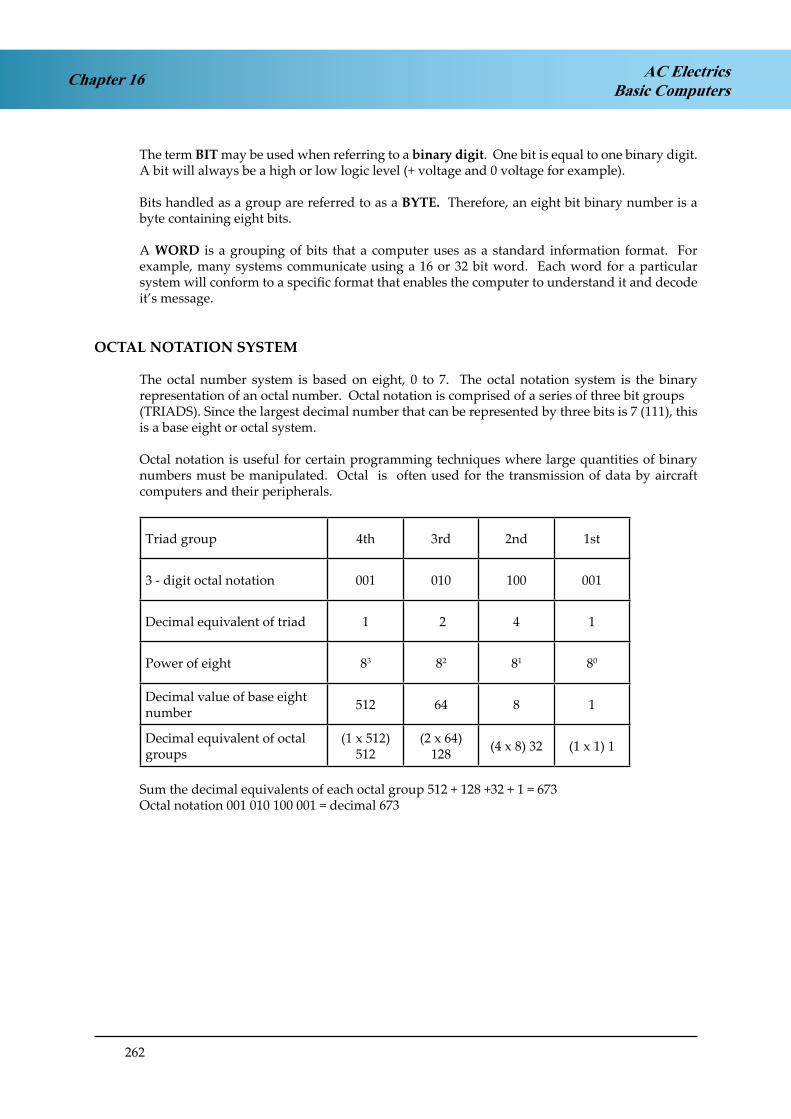
262
Chapter 16 AC ElectricsBasic Computers
The term BIT may be used when referring to a binary digit. One bit is equal to one binary digit. A bit will always be a high or low logic level (+ voltage and 0 voltage for example).
Bits handled as a group are referred to as a BYTE. Therefore, an eight bit binary number is a byte containing eight bits.
A WORD is a grouping of bits that a computer uses as a standard information format. For example, many systems communicate using a 16 or 32 bit word. Each word for a particular system will conform to a specific format that enables the computer to understand it and decode it’s message.
OCTAL NOTATION SYSTEM
The octal number system is based on eight, 0 to 7. The octal notation system is the binary representation of an octal number. Octal notation is comprised of a series of three bit groups(TRIADS). Since the largest decimal number that can be represented by three bits is 7 (111), this is a base eight or octal system.
Octal notation is useful for certain programming techniques where large quantities of binary numbers must be manipulated. Octal is often used for the transmission of data by aircraft computers and their peripherals.
Triad group 4th 3rd 2nd 1st
3 - digit octal notation 001 010 100 001
Decimal equivalent of triad 1 2 4 1
Power of eight 83 82 81 80
Decimal value of base eight number 512 64 8 1
Decimal equivalent of octal groups
(1 x 512)512
(2 x 64)128 (4 x 8) 32 (1 x 1) 1
Sum the decimal equivalents of each octal group 512 + 128 +32 + 1 = 673Octal notation 001 010 100 001 = decimal 673

263
Chapter 16AC ElectricsBasic Computers
HEXADECIMAL NUMBER SYSTEM
The hexadecimal (hex) system uses base 16. The main purpose of this system is to represent the very large numbers of memory locations used in micro controllers and microprocessors.
The hexadecimal system uses the numbers 0 to 9 along with the letters A to F to make up the16 symbols. The table below shows the relationship between hexadecimal, decimal and binary numbers:
Hexadecimal Decimal Binary
0 0 0000
1 1 0001
2 2 0010
3 3 0011
4 4 0100
5 5 0101
6 6 0110
7 7 0111
8 8 1000
9 9 1001
A 10 1010
B 11 1011
C 12 1100
D 13 1101
E 14 1110
F 15 1111
An important point to recognise about the hexadecimal system is that 4 binary digits represent a single hexadecimal digit. This is significant because a 16 bit binary code can be represented by a 4 digit hexadecimal number.

264
Chapter 16 AC ElectricsBasic Computers
DIGITAL COMPUTER COMPONENTS(Hardware)
Having discussed the language in which computers work, and remembering that binary is the basic language in which calculations are carried out and information is stored in memory, we shall now look at the construction of a basic computer.
All computers have the basic components shown in the diagram below:
Figure 1 A Basic Digital ComputerFigure 16.1 A Basic Digital Computer
CENTRAL PROCESSING UNIT (CPU)
The CPU performs, organises and controls all the operations the computer can carry out. It is really the brain of the computer. What the CPU can do is controlled by an instruction set.
The CPU itself consists of:
Arithmetic Logic Unit: ¾ The ALU performs arithmetic calculations and logical operations in the binary number system.
Shift Registers: ¾ The shift registers are temporary stores; one of them, called the accumulator contains the data actually being processed.
Control Unit ¾ : The control unit contains the computer’s clock. This is a crystal controlled oscillator which generates timing pulses at a fixed frequency, typically be-tween 120 and 45MHz. This synchronises computer operations.

265
Chapter 16AC ElectricsBasic Computers
INPUT OUTPUT DEVICES
The CPU accepts digital signals from the input devices, keyboard, mouse or modem, in the case of a PC, via its input port. In an aircraft these could be various sensors, Rad Alt, Baro Alt, TAS, fuel flow, etc.
After processing these are fed out via its output port to a Visual Display Unit (Monitor) or printer. In an aircraft the output may be fed to an EFIS Symbol Generator or the FMS Control Display Unit (CDU).
BIOS (Basic Input Output System) converts the input signals to a form the computer can work with and converts the outputs to a form the operator or another aircraft system can understand.
MEMORY
¾ Working Memory: A computer needs a working memory to run the programme of instructions (software) it has to execute. If the programme is fixed as in a computer controlled piece of equipment, the memory only has to be read. To do this a Read Only Memory (ROM) is used. This ROM is programmed by the manufacturer. A Programmable Read Only Memory (PROM), Erasable Programmable Read Only Memory (EPROM), or Electronically Erasable Programmable Memory (EEPROM) would be used if the user wanted to construct or modify the programme himself and keep it permanently in the memory.
Memory that retains data when the power is switched off is called NON VOLATILE MEMORY. Memory that loses data in the event of a power failure or switch off is called VOLATILE MEMORY.
If the programme has to be changed during operation, then the memory must be able to be written to as well as read. To do this Random Access Memory (RAM) this allows instructions to be written in, read out and altered at will. A RAM is also required to store the data for processing as this also will change continually. RAM is normally Volatile Memory.
¾ Permanent Memory: As stated above RAM is volatile and work is lost when power is removed. Permanent storage for computer programmes and the work they generate is usually in the form of magnetic disks. Both floppy and hard disks are permanent stores of computer data. Their storage capacity is measured in megabytes or gigabytes. Hard disks are usually integral parts of the hardware. Floppy disks can be inserted and removed from drives and are transportable and securable.
¾ Electronically Alterable Read Only Memory (EAROM): This is a special type of ROM that can be electronically altered. It is used in the data base of the Flight Management System Computer. This contains a worldwide data base of all airfields, navigation aids, airways, etc. Of course, periodically, frequencies and airways change and the data base needs to be updated.
This is achieved on a 28 day cycle when Jeppeson issue an update floppy disk to their client airlines. The disk is inserted into the FMS Control Display Unit, powered up and the new data inserted and the old data cancelled.

266
Chapter 16 AC ElectricsBasic Computers
AIRCRAFT SYSTEMS
Systems which are computer controlled include:
¾ Flight Management System (FMS)
¾ Digital Flight Guidance System (DFGS)
¾ Ground Proximity Warning System (GPWS)
¾ Traffic Alert Collision Avoidance System (TCAS)
Of course Fly by Wire aircraft take computer control very much further, when the whole flight envelope is controlled by computer process with inputs from the crew when necessary.
Current design favours the use of dedicated computers for each separate system. In the future however we may see sharing of computer power in the form of an Integrated Hazard Warning System (IHWS). Here a powerful central processor, with appropriate back up, handles inputs from the stall warning system, windshear detection, GPWS, TCAS and even the Weather Radar, processes the information and prioritises warnings to the crew.
Analogue to Digital Conversion (A to D): Many aircraft sensors produce analogue information in the form of varying voltages, pressures, temperatures, etc. Of course digital computers use digital (binary) information and a device called an Analogue to Digital Converter is required in the interface between the sensor and the computer input device.
Digital to Analogue Conversion (D to A): When a digital computer has to pass information to an analogue device the process is reversed and a Digital to Analogue Converter is used.

267
Chapter 16AC ElectricsBasic Computers
QUESTIONS
1. A basic digital computer consists of:
1. input peripherals2. central processing unit3. inertial unit4. memory5. auto brightness control6. output peripherals
a. 1, 2, 3, 4 and 6b. 1, 2, 4 and 6c. 1, 4, 6 onlyd. 2, 3, 4, and 6
2. The Central Processing Unit (CPU) consists of:
1. input device2. output device3. Arithmetic Logic Unit (ALU)4. Shift Registers5. Control Unit6. Hard disk
a. 1, 2, 3, and fiveb. 3, 4, and 6c. 1, 2, 5, and 6d. 3, 4, 5,
3. In computer terminology an input peripheral device would be:
a. a hard diskb. a floppy diskc. a keyboardd. a screen display unit
4. The two types of binary logic are:
a. positive and negativeb. variable and negative c. positive and reversible d. variable and reversible
5. In computer terminology an output peripheral device would be:
a. a floppy diskb. a hard diskc. a screen display unitd. a keyboard

268
AC ElectricsBasic ComputersChapter 16
6. In computer terminology a memory which loses its data when power is removed is called:
a. non-volatileb. non-permanentc. non-retentived. volatile
7. In computer terminology a memory which retains its data when power is removed is called:
a. non-volatileb. volatilec. RAMd. ROM
8. Examples of input peripheral devices are:
1. mouse2. modem3. printer4. screen display unit5. keyboard
a. 2, 3, 4, 5.b. 1, 2, 5.c. 1, 5.d. 1, 2, 3.
9. In computer terminology “software” refers to:
a. the memory system floppy disks, hard disks, etcb. the RAM and ROM capacityc. the programme of instructionsd. the BIOS
10. In computer terminology “hardware” refers to:
a. the digital computer components, keyboard, monitor, CPU, etcb. the permanent memory system and its capacityc. the RAM capacityd. the programme of instructions
11. Memory capacity in a digital computer is expressed in:
a. Bits (Mbits, Gbits)b. Bytes (Mbytes, Gbytes)c. ROM capacityd. RAM capacity
12. The smallest information element in a digital system is:
a. byteb. digitc. electrond. bit

269
Chapter 16AC ElectricsBasic Computers
13. A group of binary digits handled as a group is referred to as a:
a. byteb. mega bitc. giga bitd. bits
14. Convert the decimal number 7 to its binary equivalent:
a. 1110b. 111c. 1101d. 100
15. Convert binary 1110 to its decimal equivalent:
a. 13b. 14c. 15d. 16
16. The computer language in which calculations are carried out and information is stored in memory is:
a. decimalb. hexadecimalc. octald. binary
17. The computer language system which uses the base 16 is known as:
a. septagesimalb. hectadecimalc. hexadecimald. octal
18. The computer language system which uses the base 8 is called:
a. decimalb. binaryc. octald. hexadecimal
19. The number system which uses the numbers 0 to 9 followed by the letters A to F is:
a. alpha numericb. hexadecimalc. octald. numeric alpha

270
AC ElectricsBasic ComputersChapter 16
20. In a digital computer binary 1 is represented by +5 volts and Binary 0 by earth. This is an example of:
a. negative logicb. bipolar logicc. positive logicd. analog system
21. In a negative logic system:
a. binary 1 is a low level, binary 0 is a high levelb. binary 1 is a high level, binary 0 is a low levelc. binary 1 is positive, binary 0 is negatived. binary 1 and binary 0 are equal levels above and below zero
22. The permanent memory of a digital computer usually takes the form of:
a. Integrated circuits rated in megabytesb. shift registers whose capacity is rated in mega or gigabytesc. floppy or hard disks whose capacity is measured in mega or gigabytesd. Central Processing Unit
23. The purpose of the Arithmetic Logic Unit within the Central Processing Unit is to:
a. act as a temporary store for information being processedb. perform calculations in the binary number systemc. perform calculations in the binary, octal or hexadecimal systemd. perform all clock functions based on the computer clock frequency (clock time)
24. Within the Central Processing Unit, the temporary stores and accumulator which handle the data during processing are called:
a. Arithmetic Logic Unit (ALU)b. Shift Registersc. Control Unitd. BIOS
25. Aircraft data in analog form, before being processed by a computer must be passed through a:
a. digital to analog converter (D to A)b. EPROMc. EAROMd. analog to digital converter (A to D)

271
Chapter 16AC ElectricsBasic Computers

272
AC ElectricsBasic ComputersChapter 16
ANSWERS
1 B
2 D
3 C
4 A
5 C
6 D
7 A
8 B
9 C
10 A
11 B
12 D
13 A
14 B
15 B
16 D
17 C
18 C
19 B
20 C
21 A
22 C
23 B
24 B
25 D

273
Chapter 17AC ElectricsSemiconductors
CHAPTER SEVENTEEN
SEMICONDUCTORS
Contents
AN INTRODUCTION TO SEMICONDUCTORS . . . . . . . . . . . . . . . . . . . . .275
CONDUCTORS AND INSULATORS . . . . . . . . . . . . . . . . . . . . . . . . . . . .275
SEMICONDUCTORS . . . . . . . . . . . . . . . . . . . . . . . . . . . . . . . . . . . . .276
N-TYPE MATERIAL . . . . . . . . . . . . . . . . . . . . . . . . . . . . . . . . . . . . . .277
P-TYPE MATERIAL . . . . . . . . . . . . . . . . . . . . . . . . . . . . . . . . . . . . . .278
CURRENT FLOW . . . . . . . . . . . . . . . . . . . . . . . . . . . . . . . . . . . . . . .278
THE P-N JUNCTION . . . . . . . . . . . . . . . . . . . . . . . . . . . . . . . . . . . . .279
REVERSE BIAS . . . . . . . . . . . . . . . . . . . . . . . . . . . . . . . . . . . . . . . . .280
FORWARD BIAS . . . . . . . . . . . . . . . . . . . . . . . . . . . . . . . . . . . . . . . .280
THE JUNCTION DIODE . . . . . . . . . . . . . . . . . . . . . . . . . . . . . . . . . . .280
THE BI-POLAR OR JUNCTION TRANSISTOR . . . . . . . . . . . . . . . . . . . . . .281
SUMMARY . . . . . . . . . . . . . . . . . . . . . . . . . . . . . . . . . . . . . . . . . . .283

274
Chapter 17 AC ElectricsSemiconductors

275
Chapter 17AC ElectricsSemiconductors
AN INTRODUCTION TO SEMICONDUCTORS
Most people own some type of hand held or desktop calculator these days. The cost of these useful devices varies depending on sophistication, simple ones are given away free as advertising gimmicks, yet there is more computing power inside one of these tiny machines than took Neil Armstrong to the moon!!
Transistorisation and miniaturisation have enabled us to build ever more sophisticated electronics and package them in ever smaller units. Modern pilots rely heavily on the electronic flight systems incorporated in their aircraft and therefore must have an understanding of how transistors, or more specifically semi-conductors, work.
CONDUCTORS AND INSULATORS
Before proceeding with the explanation about how semiconductors work, let us remind ourselves about the general atomic construction of conductors and insulators.
Figure 7.1. A Hydrogen Atom.Figure 17.1 A Hydrogen Atom
The most simple atom is the Hydrogen atom. It consists of a nucleus, containing one proton (positively charged) and one neutron (neutrally charged), and an electron (negatively charged) orbiting about the nucleus.
Conductors and insulators have more complex atoms with an increasing (equal) number of neutrons, protons and electrons with the latter orbiting the nucleus in multiple orbits or shells.
These atoms are held together by the bonds formed between the valence electrons in the outer shells and arrange themselves into a lattice type arrangement equidistant from each other. Electrons in the outer shells are less tightly bonded to their parent atom than those on the inner shells and are free to move from one atom to the next.
These electrons, known as free electrons, form the basis for current flow within the material. Conductors, formed by atoms held together by electrovalent bonds, possess large numbers of free electrons, this allows current to flow easily through the material or put another way; the material has high conductivity (low resistivity). Gold, silver and copper are all examples of good conductors.
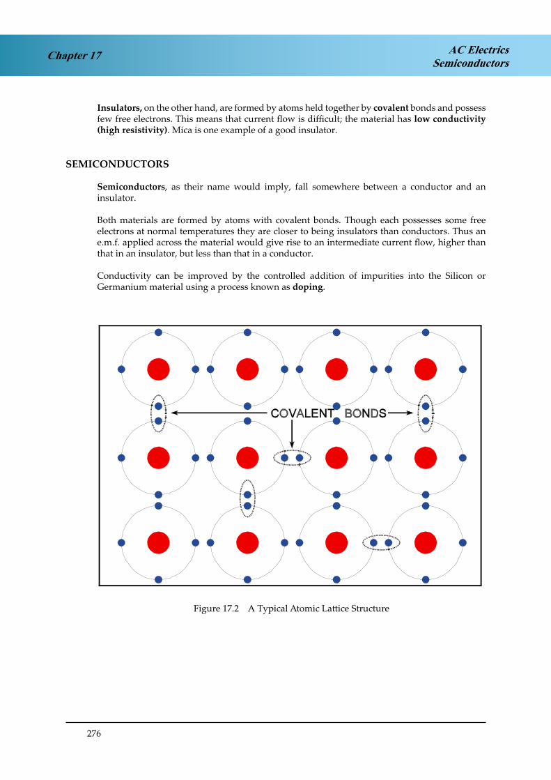
276
Chapter 17 AC ElectricsSemiconductors
Insulators, on the other hand, are formed by atoms held together by covalent bonds and possess few free electrons. This means that current flow is difficult; the material has low conductivity (high resistivity). Mica is one example of a good insulator.
SEMICONDUCTORS
Semiconductors, as their name would imply, fall somewhere between a conductor and an insulator.
Both materials are formed by atoms with covalent bonds. Though each possesses some free electrons at normal temperatures they are closer to being insulators than conductors. Thus an e.m.f. applied across the material would give rise to an intermediate current flow, higher than that in an insulator, but less than that in a conductor.
Conductivity can be improved by the controlled addition of impurities into the Silicon or Germanium material using a process known as doping.
Figure 7.2. A Typical Atomic Lattice Structure.Figure 17.2 A Typical Atomic Lattice Structure

277
Chapter 17AC ElectricsSemiconductors
N-TYPE MATERIAL
By doping the Silicon or Germanium with Arsenic or Antimony, atoms which have 5 valance electrons in their outer shell are introduced into the lattice structure. The ratio of impurity atoms to original atoms (doping ratio) is in the order of 1:108.
Figure 7.3. ‘N’ Type Material..Figure 17.3 ‘N’ Type Material
Four of the five electrons form covalent bonds with the surrounding atoms, the 5th electron, having no such ties, becomes a free electron. Conductivity through the material is thus increased.
We call this type of material N-type because of the surfeit of free electrons which are of course negatively charged. However, it should be noted that the material remains electrically neutral, for each free electron there is a fixed positive ion within the material.

278
Chapter 17 AC ElectricsSemiconductors
P-TYPE MATERIAL
By doping with impurities such Aluminium or Idium, again in the same doping ratio as above, atoms with only three valence electrons in their outer shell are introduced.
Figure 7.4. ‘P’ Type Material..Figure 17.4 ‘P’ Type Material
This time there are only 3 electrons to form the covalent bonds, one is missing. In other words there is a hole in the valent structure.
Electrons from adjacent atoms tend to move into these holes thus creating holes around the donor atoms which in turn ‘steal’ electrons from their neighbours moving the hole on further.
This apparent movement of holes increases the conductivity of the material.
Because of the shortage of electrons the material is classified as P-type.
Again, it should be noted, it possesses no electrical charge, there being an equal number of holes and fixed negative ions.
CURRENT FLOW
Applying an e.m.f. across a piece of N-type material would cause the free electrons to migrate towards the positive terminal.
Any electrons leaving the material at the positive terminal are replaced by electrons entering at the negative terminal, thus the overall balance between free electrons fixed positive ions is maintained.

279
Chapter 17AC ElectricsSemiconductors
In P-type the situation is more complex, but in general, electrons are attracted into the positive terminal creating holes in this region.
The holes ‘migrate’ towards the negative terminal and are ultimately filled by an electron entering at that point.
Hence in P-type semiconductor material we can consider current flow as the drift of holes in the conventional direction, namely from the positive to the negative terminal. Again, overall balance is maintained between electrons and fixed negative ions.
THE P-N JUNCTION
If we fuse two small pieces of N and P-type materials together, by a process similar to welding, some free electrons from the N-type material migrate across the boundary into the P-type and similarly, holes migrate the other way.
This migration produces a charged region known as the Depletion Layer and creates a Barrier Potential restricting further electron/hole movement. This barrier potential may be represented as an imaginary battery, though it should be remembered, the regions of increased positive and negative charge exist only across the junction. The material as a whole possesses no electrical charge.
Figure 7.5. The P-N Junction.Figure 17.5 The P-N Junction

280
Chapter 17 AC ElectricsSemiconductors
REVERSE BIAS
If we now connect an external e.m.f. across the P-N material, as shown in Figure 17.6. A more electrons are drawn across the barrier into the P-type material and more holes are drawn to the N-type.
This deepens the depletion layer and further electron/hole migration is prevented. Apart from a small leak current, in the order of µA, no significant current flows. The junction is said to be reverse biased.
Figure 7.6. Reverse and Forward Bias.Figure 17.6 Reverse and Forward Bias
FORWARD BIAS
By applying the external e.m.f, as shown in Figure 17.6 B, the direction of the electric field is such as to produce a drift of holes in the P-type material to the right, and of free electrons in the N-type to the left.
In the junction region, free electrons and hole combine, thus the barrier potential is overcome.
THE JUNCTION DIODE
It can be seen from Figure 17.7 that current can only flow in one direction through a semiconductor formed from P-N type material.
In other words the material acts as a rectifier and has similar conduction characteristics of a thermionic diode (valve).

281
Chapter 17AC ElectricsSemiconductors
It is therefore referred to as a Junction Diode.
Figure 7.7. The Junction Diode and its Circuit Symbol.Figure 17.7 The Junction Diode and its Circuit Symbol
THE BI-POLAR OR JUNCTION TRANSISTOR
Construction: This is a combination of two junction diodes and consists of either a thin layer (typically 25 µm) of p-type semiconductor sandwiched between two n-type semiconductors (as shown in Figure. 17.8 left) which is referred to as an n-p-n transistor, or a thin layer of n-type semiconductor sandwiched between two p-type semiconductors (as shown in Figure 17.8 right), which is referred to as a p-n-p transistor.
Figure 7.8. The Bi-Polar Transistor.Figure 17.8 The Bi-Polar Transistor

282
Chapter 17 AC ElectricsSemiconductors
The three regions of either type of transistor are known respectively as Collector, Base and Emitter.
The circuit symbol for each transistor differs only in regard to the direction of the arrow between Base and Emitter.
The arrow always represents conventional current flow; thus for an N-P-N transistor it points from Base to Emitter, and for a P-N-P, from Emitter to Base.
Operation. N-P-N Transistor: If we apply an e.m.f. across the Collector - Emitter region, as shown in Figure 17.9 left, no current flows.
However, if we now add an e.m.f. between across the Base - Emitter region, as shown in Figure 17.9 right, a large current flows from Emitter to Collector.
Figure 7.9. Transistor Conduction.Figure 17.9 Transistor Conduction
The theory governing the flow of current in a transistor is complex and generally beyond the scope of this course, but in simple terms here is what happens.
By applying an e.m.f., or Bias voltage, between Base and Emitter of an N-P-N transistor, the junction is forward biased and a large number of free electrons are attracted to the Base region.
However, in the relatively thin Base region, few holes are produced for these free electrons to combine with, so the surplus diffuse into the Collector region where they migrate towards the applied positive potential.
Holes that have combined with free electrons are replaced as an electron leaves the Base region for the positive terminal of the Bias supply.

283
Chapter 17AC ElectricsSemiconductors
Consequently, a relatively small Base - Emitter current flow produces a large Emitter - Collector flow.
Operation. P-N-P Transistor: A P-N-P transistor’s operation is similar in all respects to that of an N-P-N transistor except that the applied e.m.f.s are reversed.
SUMMARY
The ability of a transistor to control a large Emitter - Collector current by means of a small Base - Emitter current means it can act as a switch or amplifier, by turning the Base - Emitter current on and off, or as an amplifier by superimposing a small alternating current signal on the Bias voltage. In conjunction with the Junction Diode and other electronic components, such as resistors, capacitors and inductors, the applications for the transistor are almost limitless.
Further more, the ability to control precisely those areas to which doping is applied, using Photo-etching techniques, means that all of the above components can be incorporated into a highly sophisticated and complex circuit within a single, small, piece of silicon. The ubiquitous computer chip is one such example.
For the future, as production techniques improve, faster, more powerful circuits will be contained in ever smaller packages, leading in turn to more sophisticated technology being incorporated in the modern airliner.

284
Chapter 17 AC ElectricsSemiconductors

285
Chapter 18AC ElectricsLogic Gates
CHAPTER EIGHTEEN
LOGIC GATES
Contents
AN INTRODUCTION TO LOGIC GATES . . . . . . . . . . . . . . . . . . . . . . . . .287
BINARY LOGIC . . . . . . . . . . . . . . . . . . . . . . . . . . . . . . . . . . . . . . . .287
TRUTH TABLES . . . . . . . . . . . . . . . . . . . . . . . . . . . . . . . . . . . . . . . .287
GATE SYMBOLS . . . . . . . . . . . . . . . . . . . . . . . . . . . . . . . . . . . . . . . .287
POSITIVE AND NEGATIVE LOGIC . . . . . . . . . . . . . . . . . . . . . . . . . . . . .288
THE ‘AND’ GATE . . . . . . . . . . . . . . . . . . . . . . . . . . . . . . . . . . . . . . .288
THE ‘OR’ GATE . . . . . . . . . . . . . . . . . . . . . . . . . . . . . . . . . . . . . . . .289
THE ‘INVERT’ OR ‘NOT’ GATE . . . . . . . . . . . . . . . . . . . . . . . . . . . . . . .290
THE ‘NAND’ GATE . . . . . . . . . . . . . . . . . . . . . . . . . . . . . . . . . . . . . .291
THE ‘NOR’ GATE . . . . . . . . . . . . . . . . . . . . . . . . . . . . . . . . . . . . . . .292
THE ‘EXCLUSIVE OR’ GATE. . . . . . . . . . . . . . . . . . . . . . . . . . . . . . . . .293
QUESTIONS . . . . . . . . . . . . . . . . . . . . . . . . . . . . . . . . . . . . . . . . . .295
ANSWERS . . . . . . . . . . . . . . . . . . . . . . . . . . . . . . . . . . . . . . . . . . .298

286
Chapter 18 AC ElectricsLogic Gates

287
Chapter 18AC ElectricsLogic Gates
AN INTRODUCTION TO LOGIC GATES
Logic gates, or gates, are a type of fundamental function performed by computers and related equipment. A single integrated circuit (IC) within a computer contains several gate circuits. Each gate may have several inputs and must have only one output.
There are six commonly used logic gates, the ‘AND’, the ‘OR’, the ‘INVERT’, the ‘NOR’, the ‘NAND’ and the ‘EXCLUSIVE OR’. The name of each gate represents the function it performs.
BINARY LOGIC
Logic gates are of a binary nature, i.e. the inputs and the outputs are in one of two states expressed by the digital notation ‘1’ or ‘0’. Other corresponding expressions are also frequently used, they are:
¾ ‘1’ - on; true; high (H); closed; engaged
¾ ‘0’ - off; false; low (L); open; disengaged
TRUTH TABLES
Truth Tables are a systematic means of displaying binary data. Truth tables illustrate the relationship between a logic gate’s inputs and outputs. This type of data display can be used to describe the operation of a gate. For troubleshooting purposes, the truth table data is often reviewed in order to determine the correct output signal for a given set of inputs.
GATE SYMBOLS
Each logic gate has a symbol of a specific shape. The symbols are designated to “point” in a given direction, that is, the inputs are always listed on the left of the symbol and the outputs on the right.
Since logic gate operate using digital data, all input and output signals will be comprised of ‘1’s or ‘0’s. Typically the symbol ‘1’ represents ‘ON’ or voltage positive, and the symbol ‘0’ represents ‘OFF’, or voltage negative. Voltage negative is often referred to as zero voltage or the circuit’s ground.

288
Chapter 18 AC ElectricsLogic Gates
POSITIVE AND NEGATIVE LOGIC
As stated earlier, logic circuit input and output signals consist of two distinct levels. These levels are often referred to as ‘binary 1’ and ‘binary 0’. The actual voltage levels required to achieve a ‘binary 1’ or ‘binary 0’ may vary between circuits.
If ¾ positive logic is used in the digital circuit, a ‘binary 1’ equals a high voltage level and a ‘binary 0’ equals a low voltage level. The actual voltage values may be either both positive or both negative, or one positive and one negative. The only stipulation for positive logic is that a ‘binary 1’ is created by a greater positive voltage than a ‘binary 0’ . Each signal represents the greater positive voltage value as a ‘binary 1’, therefore each example employs the positive logic concept. Most digital systems employ positive logic throughout the entire computer and related component circuitry.
The ¾ negative logic concept defines ‘binary 1’ as the lower voltage value and ‘binary 0’ as the higher voltage value (more positive). Although less popular, negative logic is used in some systems in order to meet certain design parameters.
THE ‘AND’ GATE
The ‘AND’ gate is used to represent a situation where all inputs to the gate must be ‘1’ (on) to produce a ‘1’ (on) output. To be an ‘AND’ gate, input No. 1 and input No. 2 and input No. 3 etc, must be ‘1’ to produce a ‘1’ output. If any input is a ‘0’ (off), the output will be ‘0’ (off). The symbol and the truth table for a two-input AND gate are illustrated in Figure 18.1.
Figure 7.10. The Symbol and Truth Table for an 'AND' Gate.
Figure 18.1 The Symbol and Truth Table for an ‘AND’ Gate

289
Chapter 18AC ElectricsLogic Gates
A simple ‘AND’ circuit may also be represented by two switches in series used to turn on a light as shown in Figure 18.1. If both switches (inputs) are ‘1’ (on), the light will turn ‘1’ (on). If either switch is ‘0’ (off), the light will be ‘0’ (off).
The ‘AND’ gate is sometimes called an ‘ALL or NOTHING’ gate.
THE ‘OR’ GATE
The ‘OR’ gate is used to represent a situation where any input being ‘1’ (on) will produce a ‘1’ (on) output. To be an ‘OR’ gate, input No. 1 or input No. 2 or input No. 3, etc, must be ‘1’ to produce a ‘1’ output.
Only if all inputs become ‘0’ will the ‘OR’ gate produce a ‘0’ output. If any input is a ‘1’, regardless of the other input values the ‘OR’ gate will produce a ‘1’ output.
A two-input ‘OR’ gate symbol and corresponding truth table are illustrated in Figure 18.2.
A simple ‘OR’ circuit may be comprised of two switches in parallel controlling one light. If either switch is ‘1’ (on), the light will turn ‘1’ (on).
The OR gate may be called an “ANY or ALL“ gate.
Figure 7.11. Representation of the 'OR' Gate.
Figure 18.2 Representation of the ‘OR’ Gate

290
Chapter 18 AC ElectricsLogic Gates
THE ‘INVERT’ OR ‘NOT’ GATE
The ‘INVERT’ gate is used to reverse the condition of the input signal. The ‘INVERT’ gate contains only one input and one output, and is most often used in conjunction with other gates.
The ‘INVERT’ gate is sometimes referred to as a ‘NOT’ gate. The symbol and truth table for an ‘INVERT’ gate are shown in Figure 18.3.
An ‘INVERT’ circuit might be comprised of a switch controlling a normally closed relay which turns on or off a light. As also illustrated in Figure 18.3, if the switch is turned ‘1’ (on), the light is ‘0’ (off).
Figure 7.12. Representation of the 'INVERT' or 'NOT' Gate.
Figure 18.3 Representation of the ‘INVERT’ or ‘NOT’ Gate

291
Chapter 18AC ElectricsLogic Gates
THE ‘NAND’ GATE
The ‘NAND’ gate is an ‘AND’ gate with an inverted output. The output of this gate will be ‘1’ if any input is ‘0’. This is the exact opposite of an ‘AND’ gate. The representations of a ‘NAND’ gate are shown in Figure 18.4.
The ‘NAND’ gate circuit illustrated in Figure 18.4 shows if either switch is closed there will be no output.
Figure 7.13. The Representations of the 'NAND' Gate.Figure 18.4 The Representations of the ‘NAND’ Gate

292
Chapter 18 AC ElectricsLogic Gates
THE ‘NOR’ GATE
The ‘NOR’ gate is an ‘OR’ gate with an inverted output. This results in a gate where any input being ‘1’ will create a ‘0’ output. The ‘NOR’ symbol, the truth table, the electronic circuit and the relay circuit which represent a ‘NOR’ gate are all illustrated in Figure 18.5.
Figure 7.14. Representations of the 'NOR' Gate.Figure 18.5 Representations of the ‘NOR’ Gate

293
Chapter 18AC ElectricsLogic Gates
THE ‘EXCLUSIVE OR’ GATE
The’ EXCLUSIVE OR’ gate is designed to produce a ‘1’ output whenever its input signals are dissimilar.
An illustration of the representations of the ‘EXCLUSIVE OR’ gate is shown in Figure 18.6. This gate compares a maximum of two input signals to determine its output.
As shown in the truth table within Figure 18.6, if the input signals have like values, the output will be ‘0’, if the input signals have unlike values, the output will be ‘1’
Figure 7.15. Representations of the 'EXCLUSIVE OR' Gate.
Figure 18.6 Representations of the ‘EXCLUSIVE OR’ Gate

294
Chapter 18 AC ElectricsLogic Gates
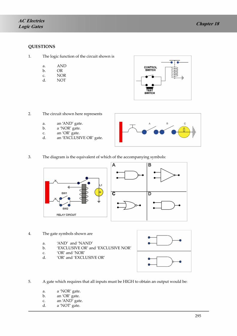
295
Chapter 18AC ElectricsLogic Gates
QUESTIONS
1. The logic function of the circuit shown is
a. AND b. OR c. NOR d. NOT
2. The circuit shown here represents
a. an ‘AND’ gate. b. a ‘NOR’ gate. c. an ‘OR’ gate.d. an ‘EXCLUSIVE OR’ gate.
3. The diagram is the equivalent of which of the accompanying symbols:
4. The gate symbols shown are
a. ‘AND’ and ‘NAND’b. ‘EXCLUSIVE OR’ and ‘EXCLUSIVE NOR’c. ‘OR’ and ‘NOR’d. ‘OR’ and ‘EXCLUSIVE OR’
5. A gate which requires that all inputs must be HIGH to obtain an output would be:
a. a ‘NOR’ gate. b. an ‘OR’ gate.c. an ‘AND’ gate. d. a ‘NOT’ gate.

296
AC ElectricsLogic GatesChapter 18
6. This diagram represents:
a. an inverter.b. an ‘AND’ gate.c. an ‘EXCLUSIVE NOR’ gate.d. an ‘OR’ gate.
7. To obtain logic ‘0’ at output ‘Z’ there must be:
a. logic ‘1’ at ‘X’ and logic ‘0’ at ‘Y’. b. logic ‘0’ at ‘X’ and logic ‘1’ at ‘Y’. c. logic ‘1’ at ‘X’ and logic ‘1’ at ‘Y’. d. logic ‘0’ at ‘X’ and logic ‘0’ at ‘Y’.
8. A transistor:
a. can only be used as an amplifier.b. can be used as a demi-conductor to act as an automatic switch or an amplifier. c. is an inverted silicon controlled rectifier.d. can be used as a semi-conductor to act as an automatic switch or an amplifier.
9. A transistor:
a. is made up of crystals in the arrangement of emitter, base and collector. b. is made up of crystals in the arrangement of emitter, collector and base. c. is made up of crystals in the arrangement of collector, emitter and base. d. requires a current of ten amps through the base to transmit.
10. A gate with only one input and one output:
a. cannot be a ‘double’ gate. b. is a ‘NOT’ gate.c. can only be a ‘semi-gate’. d. cannot be a ‘NOT’ gate.
11. The two most commonly used gates are:
a. ‘NOT’ and ‘NOR’b. ‘OR’ and ‘EXCLUSIVE AND’c. ‘AND’ and ‘OR’d. ‘AND’ and ‘NAND’

297
Chapter 18AC ElectricsLogic Gates
12. Truth tables illustrate the relationship between:
a. inputs and outputs.b. integrated gates for trouble shooting. c. the sequence of operation of the gates. d. electronic and electrical circuits.
13. The output expression for this type of gate is:
a. ‘AND’b. ‘EXCLUSIVE NOR’ c. ‘EXCLUSIVE OR’d. ‘EXCLUSIVE NOT’
14. In order to energise the relay shown in this circuit, the logic state at the inputs must be:
a. logic ‘0’ at points ‘A’ and ‘B’.b. logic ‘0’ at point ‘A’ and logic ‘1’ at point ‘B’. c. logic ‘1’ at points ‘A’ and ‘B’.d. always identical at points ‘A’ and ‘B’.
15. The type of logic gate represented by this diagram is:
a. ‘OR’b. ‘NAND’ c. ‘AND’ d. ‘NOT’

298
AC ElectricsLogic GatesChapter 18
ANSWERS
1 B
2 A
3 C
4 A
5 C
6 D
7 C
8 D
9 A
10 B
11 C
12 A
13 C
14 C
15 D


300
Chapter 19 Radio PropagationProperties of Radio Waves

301
Chapter 19Radio PropagationProperties of Radio Waves
CHAPTER NINETEEN
PROPERTIES of RADIO WAVES
Contents
INTRODUCTION . . . . . . . . . . . . . . . . . . . . . . . . . . . . . . . . . . . . . . .303
THE RADIO NAVIGATION SYLLABUS . . . . . . . . . . . . . . . . . . . . . . . . . .303
ELECTRO-MAGNETIC (EM) RADIATION. . . . . . . . . . . . . . . . . . . . . . . . .303
POLARISATION . . . . . . . . . . . . . . . . . . . . . . . . . . . . . . . . . . . . . . . .304
RADIO WAVES. . . . . . . . . . . . . . . . . . . . . . . . . . . . . . . . . . . . . . . . .305
FREQUENCY BANDS . . . . . . . . . . . . . . . . . . . . . . . . . . . . . . . . . . . . .308
PHASE COMPARISON . . . . . . . . . . . . . . . . . . . . . . . . . . . . . . . . . . . .309
PRACTICE FREQUENCY (f ) - WAVELENGTH (λ) CONVERSIONS . . . . . . . . . .311
QUESTIONS . . . . . . . . . . . . . . . . . . . . . . . . . . . . . . . . . . . . . . . . . .312
ANSWERS TO PRACTICE f - λ CONVERSIONS . . . . . . . . . . . . . . . . . . . . .314
ANSWERS . . . . . . . . . . . . . . . . . . . . . . . . . . . . . . . . . . . . . . . . . . .314

302
Chapter 19 Radio PropagationProperties of Radio Waves

303
Chapter 19Radio PropagationProperties of Radio Waves
INTRODUCTION
Radio and radar systems are now an integral and essential part of aviation, without which the current intensity of air transport operations would be unsustainable. In the early days of aviation aircraft were flown with visual reference to the ground and flight at night, in cloud or over the sea was not possible. As the complexity of aircraft increased it became necessary to design navigational systems to permit aircraft to operate without reference to terrain features.
The early systems developed were, by modern standards very basic and inaccurate. They provided reasonable navigational accuracy for en-route flight over land, but only a very limited service over the oceans, and, until about 40 years ago, flight over the oceans used the traditional seafarers techniques of astro-navigation, that is using sights taken on the sun, moon, stars and planets to determine position. Developments commenced in the 1910s, continued at an increasing rate during the 1930s and 1940s and up to the present day leading to the development of long range systems which by the 1970s were providing a global navigation service.
It is perhaps ironic that, having forsaken navigation by the stars, the most widely used navigation systems in the last few years are once again space based, that is the satellite navigation systems we now take as being the norm. Whilst global satellite navigation systems (GNSS) are becoming the standard in aviation and many advocate that they will replace totally all the terrestrial systems, the ICAO view is that certain terrestrial systems will have to be retained to back-up GNSS both for en-route navigation and runway approaches.
The development of radar in the 1930s allowed air traffic control systems to be developed providing a control service capable of identifying and monitoring aircraft such that aircraft operations can be safely carried out at a much higher intensity than would be otherwise possible. Modern satellite technology is being used to provide a similar service over oceans and land areas where the provision of normal radar systems is not possible.
THE RADIO NAVIGATION SYLLABUS
The syllabus starts by looking at the nature of radio waves and how they travel through the atmosphere. This is essential to understand why different radio frequencies are selected for particular applications and also the limitations imposed. The introductory chapters also cover how radio waves are produced, transmitted, received and how information is added to and recovered from radio waves.
ELECTRO-MAGNETIC (EM) RADIATION
If a direct electric current (DC) is passed through a wire then a magnetic field is generated around the wire perpendicular to the current flow.
If an alternating electric current (AC) is passed through the wire then, because the direction of current flow is changing, the polarity of the magnetic field will also change, reversing polarity as the current direction reverses. At low frequencies the magnetic field will return to zero with the current, but as frequency increases the magnetic field will not have collapsed completely before the reversed field starts to establish itself and energy will start to travel outwards from the wire in the form of electromagnetic radiation ie radio waves.
The resulting EM energy is made up of two components, an electrical (E) field parallel to the wire and a magnetic (H) field perpendicular to the wire. (See Figure 19.1)

304
Chapter 19 Radio PropagationProperties of Radio Waves
Figure 1.3. Vertical Polarization.Figure 19.1 Vertical Polarisation
POLARISATION
The polarisation of radio waves is defined as the plane of the electric field and is dependent on the plane of the aerial. A vertical aerial will emit radio waves with the electrical field in the vertical plane and hence produce a vertically polarised wave, and a horizontal aerial will produce a horizontally polarised wave.
To receive maximum signal strength from an incoming radio wave it is essential the receiving aerial is in the same plane as the polarisation of the wave, so a vertically polarised radio wave would require a vertical aerial.
Circular polarisation can be produced in a variety of ways, one of which is using a helical antenna, (see Chapter 22). In circular polarisation the electrical (and hence magnetic) field rotates at the frequency of the radio wave. The rotation may be right handed or left handed dependent on the orientation of the aerial array.
For reception of a circularly polarised wave an aerial of the same orientation is required, or a simple dipole aerial. There are two significant advantages. Firstly in radar systems, if circular polarisation is used, when the energy is reflected from water droplets the circularity is reversed and therefore the ‘clutter’ caused by precipitation can be eliminated. Secondly, if a dipole aerial is used the orientation of the aerial is no longer critical, as it is with linear polarisation, and, clearly, this will be a major advantage in mobile systems, such as cellular phones and satellite communication and navigation systems.

305
Chapter 19Radio PropagationProperties of Radio Waves
RADIO WAVES
The length of time it takes to generate one cycle of a radio wave is known as the period and is generally signified by the Greek letter tau (τ), and measured in micro-seconds (µs). (1µs = 10-6 second).
Period ( )
If, for example, the period of one cycle of a radio wave is 0.125µs then the number of cycles produced in one second would the reciprocal of this giving:
1 =
1 = 8 000 000 cycles per second which are known as Hertz (Hz). τ 0.125 x 10⁻⁶
This is known as the frequency (f) of the wave; hence:
f = 1 (1)
τ
The frequency of radio waves is expressed in Hertz (Hz). Since the order of magnitude of the frequency of radio waves is very high, for convenience, the following terms are used to express the frequency:
Kilo-Hertz (KHz) = 103 Hz = 1 000 HzMega-Hertz (MHz) = 106 Hz = 1 000 000 HzGiga-Hertz (GHz) = 109 Hz = 1 000 000 000 Hz
So in the example above the frequency would be expressed as 8 MHz.
The speed of radio waves (c) is the same as the speed of light (which is also EM radiation) and is approximately:
300 000 000 ms-1 (= 300 x 106 ms-1), or 162 000 nautical miles per second

306
Chapter 19 Radio PropagationProperties of Radio Waves
Wavelength ( )
If a radio wave travels at 300 x 106 ms-1 and the period is 0.125 µs, then the length (λ) of each wave will be:
λ = c.τ (2)
300 x 106 x 0.125 x 10-6 = 37.5 m
This is known as the wavelength. From equation (1) this can also be stated as:
λ = c
(3) f Giving:
λ = 300 x 106
= 37.5 m 8 x 10⁶
Hence if the frequency is known then the wavelength can be determined and if the wavelength is known then the frequency can be calculated from:
f = c
(4) λ
Examples:
1. If the frequency of a radio wave is 121.5 MHz calculate the wavelength.
λ = c =
300 x 106
= 2.47 m f 121.5 x 10⁶

307
Chapter 19Radio PropagationProperties of Radio Waves
2. If the wavelength is 1515 m, what is the corresponding frequency?
f = c =
300 x 106
= 198 000 Hz = 198 x 103 Hz = 198 KHz λ 1515
For ease of calculation we can simplify the formulae:
f = 300 MHz λ (m)
λ = 300 m f (MHz)
But we must ensure that our input arguments are correct, ie to calculate the frequency the wavelength must be in metres and to calculate the wavelength the frequency must be input in MHz.
Example:
3. Determine the frequency corresponding to a wavelength of 3.2 cm.
Noting that 3.2 cm = 0.032 m the calculation becomes:
f = 300 = 9375 Mhz (or 9.375 Ghz) 0.032
4. Determine the wavelength corresponding to a frequency of 357 KHz.
Noting that 375 KHz = 0.375 MHz the calculation is:
λ = 300 = 800 m 0.375

308
Chapter 19 Radio PropagationProperties of Radio Waves
FREQUENCY BANDS
The radio part of the electro-magnetic spectrum extends from 3 KHz to 300 GHz. For convenience it is divided into 8 frequency bands. These are shown at table 1 with the frequencies, wavelengths and the uses made of the frequency bands in civil aviation. Note that each frequency band is related to its neighbouring band(s) by a factor of 10.
Frequency Band Frequencies Wavelengths Civil Aeronautical Usage
Very Low Frequency (VLF) 3 – 30 KHz 100 – 10 km Nil
Low Frequency (LF) 30 – 300 KHz 10 – 1 km NDB/ADF, LORAN C
Medium Frequency (MF) 300 – 3000 KHz 1000 – 100 mNDB/ADF, long range
communications
High Frequency (HF) 3 – 30 MHz 100 – 10 m long range communications
Very High Frequency (VHF) 30 – 300 MHz 10 – 1 m
Short range communication, VDF, VOR, ILS
localiser, marker beacons
Ultra High Frequency (UHF) 300 – 3000 MHz 100 – 10 cm
ILS glidepath, DME, SSR, Satellite communications, GNSS, long range
radars
Super High Frequency (SHF) 3 – 30 GHz 10 – 1 cmRADALT, AWR, MLS, short range
radars
Extremely High Frequency (EHF) 30 – 300 GHz 10 – 1 mm Nil
Table 1

309
Chapter 19Radio PropagationProperties of Radio Waves
PHASE COMPARISON
Some radio navigation systems use the comparison of phase between two signals to define navigational information. The first important point is that the two signals being compared must have the same frequency, otherwise any phase comparison would be meaningless. The second point is that one signal will be designated the reference signal and the other a variable signal and that the comparison must yield a positive result.
To determine the phase difference between 2 signals, first identify the position of (for example) zero phase on each of the waves, then move in the positive direction from the chosen point on the reference wave to measure the phase angle through which the reference wave has travelled before zero phase is reached on the variable wave.

310
Chapter 19 Radio PropagationProperties of Radio Waves
In this example, starting at zero phase on the reference wave (point A), we observe that the reference wave has travelled through a phase angle of 270° before zero phase is reached on the variable wave (point B), hence the phase difference is 270°.
The relationship can also be found mathematically. At the origin the phase of the reference wave is 0° (= 360°) and the phase of the variable wave is 090°. Subtracting the instantaneous phase of the variable wave from the instantaneous phase of the reference wave gives the same result, note the result must always be positive.
Reference – variable = 360° – 90° = 270°
NOTE: The phase difference must be positive, so if the calculation yields a negative result simply add 360° to get a positive answer.

311
Chapter 19Radio PropagationProperties of Radio Waves
PRACTICE FREQUENCY (f ) - WAVELENGTH (λ) CONVERSIONS
In each of the following examples, calculate the frequency or wavelength as appropriate and determine in which frequency band each of the frequencies lies.
Wavelength Frequency Frequency Band
1 198 KHz
2 2.7 m
3 5.025 GHz
4 137.5 m
5 121.5 MHz
6 3 km
7 329 MHz
8 29 cm
9 500 KHz
10 5 cm

312
Radio PropagationProperties of Radio WavesChapter 19
QUESTIONS
1. A radio wave is:
a. an energy wave comprising an electrical field in the same plane as a magnetic fieldb. an electrical field alternating with a magnetic fieldc. an energy wave where there is an electrical field perpendicular to a magnetic fieldd. an energy field with an electrical component
2. The speed of radio waves is: a. 300 km per second
b. 300 million metres per secondc. 162 nm per secondd. 162 million nm per second
3. The plane of polarisation of an electromagnetic wave is:
a. the plane of the magnetic fieldb. the plane of the electrical fieldc. the plane of the electrical or magnetic field dependent on the plane of the aeriald. none of the above
4. If the wavelength of a radio wave is 3.75 metres, the frequency is:
a. 80 KHzb. 8 MHzc. 80 MHzd. 800 KHz
5. The wavelength corresponding to a frequency of 125 MHz is:
a. 2.4 mb. 24 mc. 24 cmd. 24 mm
6. The frequency which corresponds to a wavelength of 6.98 cm is:
a. 4298 GHzb. 4.298 GHzc. 429.8 GHzd. 42.98 GHz
7. The frequency band containing the frequency corresponding to 29.1 cm is:
a. HFb. VHFc. SHFd. UHF

313
Chapter 19Radio PropagationProperties of Radio Waves
8. To carry out a phase comparison between two electromagnetic waves:
a. both waves must have the same amplitudeb. both waves must have the same frequencyc. both waves must have the same amplitude and frequencyd. both waves must have the same phase
9. The phase of the reference wave is 110° as the phase of the variable wave is 315°. What is the phase difference?
a. 205°b. 025°c. 155°d. 335°
10. Determine the phase difference between the reference wave and the variable wave: (The reference wave is the solid line and the variable wave is the dashed line)
a. 045°b. 135°c. 225°d. 315°
11. The wavelength corresponding to a frequency of 15 625 MHz is:
a. 1.92 mb. 19.2 mc. 1.92 cmd. 19.2 cm
12. Which frequency band is a wavelength of 1200 m?
a. UHFb. LFc. HFd. MF

314
Radio PropagationProperties of Radio WavesChapter 19
ANSWERS TO PRACTICE f - λ CONVERSIONS
Wavelength Frequency Frequency Band
1 1515 m 198 KHz LF
2 2.7 m 111.1 MHz VHF
3 5.97 cm 5.025 GHz SHF
4 137.5 m 2181.8 KHz MF
5 2.18 m 137.5 MHz VHF
6 3 km 100 KHz MF
7 91.2 cm 329 MHz UHF
8 29 cm 1034 MHz UHF
9 600 m 500 KHz MF
10 5 cm 6 GHz SHF
ANSWERS
1 C
2 B
3 B
4 C
5 A
6 B
7 D
8 B
9 C
10 C
11 C
12 B

315
Chapter 20Radio PropagationTheory
CHAPTER TWENTY
RADIO PROPAGATION THEORY
Contents
INTRODUCTION . . . . . . . . . . . . . . . . . . . . . . . . . . . . . . . . . . . . . . .317
FACTORS AFFECTING PROPAGATION . . . . . . . . . . . . . . . . . . . . . . . . . .317
PROPAGATION PATHS. . . . . . . . . . . . . . . . . . . . . . . . . . . . . . . . . . . .318
NON-IONOSPHERIC PROPAGATION . . . . . . . . . . . . . . . . . . . . . . . . . . .319
IONOSPHERIC PROPAGATION . . . . . . . . . . . . . . . . . . . . . . . . . . . . . .321
SKYWAVE. . . . . . . . . . . . . . . . . . . . . . . . . . . . . . . . . . . . . . . . . . . .324
PROPAGATION SUMMARY . . . . . . . . . . . . . . . . . . . . . . . . . . . . . . . . .328
SUPER-REFRACTION. . . . . . . . . . . . . . . . . . . . . . . . . . . . . . . . . . . . .329
SUB-REFRACTION . . . . . . . . . . . . . . . . . . . . . . . . . . . . . . . . . . . . . .329
QUESTIONS . . . . . . . . . . . . . . . . . . . . . . . . . . . . . . . . . . . . . . . . . .330
ANSWERS . . . . . . . . . . . . . . . . . . . . . . . . . . . . . . . . . . . . . . . . . . .332

316
Chapter 20 Radio PropagationTheory

317
Chapter 20Radio PropagationTheory
INTRODUCTION
In the context of radio waves the term propagation simply means how the radio waves travel through the atmosphere. The various propagation paths related to the frequency bands determine the uses that are made of the different frequency bands for both communication and navigation systems, and the limitations that may be imposed by the different paths that radio waves of different frequencies take through the atmosphere.
FACTORS AFFECTING PROPAGATION
There are several factors which affect the propagation of radio waves and need to be considered when discussing the propagation paths:
Attenuation. Attenuation is the term given to the loss of signal strength in a radio wave as it travels outward from the transmitter. There are two aspects to attenuation:
Absorption. As the radio wave travels outwards from a transmitter the energy is absorbed and scattered by the molecules of air and water vapour, dust particles, water droplets, vegetation, the surface of the earth and the ionosphere. The effect of this absorption, (except ionospheric) increases as frequency increases and is a very significant factor above about 1000 MHz.
Inverse Square Law. The EM radiation from an aerial spreads out as the surface of a sphere so the power available decreases with increasing distance from the transmitter. For example, if, at a certain distance from a transmitter, the field intensity is 4 Wm-2 at double the distance that energy will be spread over an area of 4 m2 and the field intensity will be 1 Wm-2. That is, power available is proportional to the inverse of the square of the range.
Figure 2.1
R
2 x R
1 m
1 m4W1W1W
1W 1W
2 m
2 m
Figure 20.1 Inverse Square Law
P ∝ 1
R2
The practical effect of this is that if it is required to double the effective range of a transmitter then the power would have to be increased by a factor of 4.

318
Chapter 20 Radio PropagationTheory
Static Interference. There is a large amount of static electricity generated in the atmosphere by weather, human activity and geological activity. The effect of static interference is greater at lower frequencies and at VHF and above the effect of interference is generally negligible. However, radio waves travelling through the ionosphere will collect interference at all frequencies. Additionally the circuitry in the receivers and transmitters also produces static interference. The static, from whatever source, reduces the clarity of communications and the accuracy of navigation systems. The strength of the required signal compared to the amount of interference is expressed as a signal to noise ratio (S/N) and for the best clarity or accuracy the unwanted noise needs to be reduced to the lowest possible levels.
Power. An increase in the power output of a transmitter will increase the range, within the limits of the inverse square law. As noted above, to double the range of a radio transmitter would require the power to be increased by a factor of 4.
Receiver Sensitivity. If internal noise in a receiver can be reduced then the receiver will be able to process weaker signals hence increasing the effective range at which a useable signal can be received, however, this is an expensive process.
Directivity. If the power output is concentrated into a narrow beam then there will be an increase in range, or a reduction in power required for a given range. However the signal will only be usable in the direction of the beam.
PROPAGATION PATHS
There are five propagation paths of which four need to be considered for aviation purposes:
PROPAGATION
NON IONOSPHERIC IONOSPHERIC
SURFACEWAVE20 KHz 50 MHz(Used 20 KHz – 2 MHz)
SKYWAVE20 KHz 50 MHz(Used 2 – 30 MHz)
SPACE WAVE>50 MHz
SATELLITE(UHF, SHF)
DUCTING<20 KHz
Ionospheric propagation is propagation affected by the properties of the ionosphere, at this stage it is only necessary to discuss skywave, satellite propagation will be considered in conjunction with global navigation satellite systems. Knowledge of propagation below 30 KHz is not required.

319
Chapter 20Radio PropagationTheory
Non-Ionospheric propagation covers the other propagation paths.The knowledge of propagation of radio waves in the VLF band is not required for the JAA examinations as there are no civil aeronautical communication or navigation systems in this band.
NON-IONOSPHERIC PROPAGATION
Surface wave. Surface wave propagation exists at frequencies from about 20 KHz to about 50 MHz (from the upper end of VLF to the lower end of VHF). The portion of the wave in contact with the surface of the earth is retarded causing the wave to bend round the surface of the earth, a process known as diffraction.
Figure 1.7. Surface Wave.Figure 20.2 Surface Wave
The range achievable is dependent on the frequency, the surface over which the wave is travelling and the polarisation of the wave. As the frequency increases, surface attenuation increases and the surface wave range decreases and is effectively non-existent above HF. The losses to attenuation by the surface of the earth are greater over land than over sea, because the sea has good electrical conductivity. Hence greater ranges are attainable over the sea. A horizontally polarised wave will be attenuated very quickly and give very short ranges.
10
100
1
10
1001 10 100 1,000 10,000
nm
LAND SEA
f (Hz)
Figure 20.3
This is the primary propagation path used in the LF frequency band and the lower part of the MF frequency band (ie frequencies of 30 KHz to 2 MHz).

320
Chapter 20 Radio PropagationTheory
An approximation to the useable range achievable over sea and land for a MF transmission at a frequency of 300 KHz is given by:
Sea: range = 3√Power
Land: range = 2√Power
So, for example, a 300 KHz transmitter with a power output of 10 KW would give a surface wave range of about 300 nm over the sea and 200 nm over the land.
Because the surface wave is retarded more over land than over sea there is a change in the direction the wave takes as it passes from land to sea. The portion of the wave which first passes over the sea accelerates and the wave bends away from the normal, that is towards the coast. This is known as coastal refraction and will be looked at in greater detail in ADF.
Space wave. The space wave is made up of two paths, a direct wave and a reflected wave.
Figure 1.6(a). Space Wave.

321
Chapter 20Radio PropagationTheory
At frequencies of VHF and above radio waves start to behave more like visible light and as we have a visual horizon with light we have a radio horizon with the radio frequencies. So the only atmospheric propagation at these frequencies is line of sight.
Figure 1.6(b). Line of Sight.
There is some atmospheric refraction which causes the radio waves to bend towards the surface of the earth increasing the range slightly beyond the geometric horizon. Since the diameter of the earth is known and the atmospheric refraction can be calculated it is possible to determine the maximum theoretical range at which a transmission can be received. The amount of refraction decreases as frequency increases but for practical purposes for the JAA syllabus the line of sight range can be calculated using the formula:
Range (nm) = 1.23 x (√HTX + √HRX)
HTX : Transmitter height in feetHRX : Receiver height in feet
At VHF and above it does not matter how powerful the transmitter is, if the receiver is below the line of sight range, it will receive nothing.
For example:What is the maximum range a receiver at 1600 ft can receive VHF transmissions from a transmitter at 1024 ft?
Range = 1.23 x (√1600 + √1024) = 1.23 x (40 + 32) = 88.6 nm
It should be noted that, regardless of the primary propagation path used, if a receiver is in line of sight with a transmitter then it is the space wave that is being received.
IONOSPHERIC PROPAGATION
Before studying ionospheric propagation it is necessary to know about the processes which produce the ionisation in the upper atmosphere and the properties of the ionosphere that produce skywave.
The Ionosphere. The ionosphere extends upwards from an altitude of about 60 km to limits of the atmosphere (notionally 1500 km). In this part of the atmosphere the pressures are very low (at 60 km the atmospheric pressure is 0.22 HPa) and hence the gaseous atoms are widely dispersed. Within this region incoming solar radiation at ultra-violet and shorter wavelengths interacts with the atoms raising their energy levels and causing electrons to be ejected from the shells of the atoms. Since an atom is electrically neutral, the result is negatively charged electrons and positively charged particles known as ions.

322
Chapter 20 Radio PropagationTheory
The electrons are continually attempting to reunite with the ions, so the highest levels of ionisation will be found shortly after midday (about 1400) local time, when there is a balance between the ionisation and the decay of the ionisation with the electrons rejoining the ions and the lowest just before sunrise (at the surface). In summer the ionisation levels will be higher than in winter, and ionisation levels will increase as latitude decreases, again because of the increased intensity of the solar radiation. Increased radiation from solar flares is unpredictable but can give rise to exceptionally high levels of ionisation, which in turn can cause severe disruption of communication and navigation systems, particularly those which are space based. It is not unusual for communication (and other) satellites to be shut down during periods of intense solar flare activity to avoid damage.
As the incoming solar energy is absorbed by the gaseous atoms the amount of energy available to ionise the atoms at lower levels reduces and hence the levels of ionisation increase with increase altitude. However, because the normal atmospheric mixing processes associated with the lower levels of the atmosphere are absent in the higher levels, gravitation and terrestrial magnetism affect the distribution of gases. This means that the increase in ionisation is not linear but the ionised particles form into discrete layers.
Km
e
E LAYER
F LAYER
D LAYER
The ionisation is most intense at the centre of the layers decreasing towards the lower and upper edges of the layers. The characteristics of these layers vary with the levels of ionisation. The lowest of these layers occurs at an average altitude of 75 km and is known as the D-region or D-layer. This is a fairly diffuse area which, for practical purposes, forms at sunrise and disappears at sunset. The next layer, at an average altitude of 125 km, is present throughout the 24 hours and is known as the E-layer. The E-layer reduces in altitude at sunrise and increases in altitude after sunset. The final layer of significance is the F-layer at an average altitude of 225 km. The F-layer splits into two at sunrise and rejoins at sunset, the F1-layer reducing in altitude at sunrise and increasing in altitude after sunset. The behaviour of the F2-layer is dependent on time of year, in summer it increases in altitude and may reach altitudes in excess of 400 km and in winter it reduces in altitude.

323
Chapter 20Radio PropagationTheory
Although, overall the levels of ionisation increase from sunrise to midday local time and then decrease until sunrise the following morning, the levels are continually fluctuating as the intensity of high energy radiation from the sun fluctuates. So it would be possible for the ionisation levels to decrease temporarily during the morning, or increase temporarily during the afternoon.
The structure of the ionosphere gives stable conditions by day and by night. Around dawn and dusk, however, the ionosphere is in a transitional state, which leads to what can best be described as electrical turbulence. The result is that around dawn and dusk, radio navigation and communication systems using the ionosphere are subject to excessive interference and disruption.

324
Chapter 20 Radio PropagationTheory
SKYWAVE
The ionisation levels in the layers increases towards the centre of the layer. This means that as a radio wave transits a layer it encounter an increasing density of ions as moves to the centre of the layer and decreasing density as it moves out of the layer. If the radio waves travel across the layer at right angles they will be retarded but will maintain a straight path. However, if the waves penetrate the layer at an angle they will be refracted away from the normal as they enter, then back towards the normal as they exit the layer.
Figure 1.10. Critical Angle (HF Band).
The amount of refraction experienced by the radio waves is dependent on both the frequency and the levels of ionisation. If the radio wave refracts to the (earth) horizontal before it reaches the centre of the layer then it will continue to refract and will return to the surface of the earth as skywave, this is total internal refraction at the layer.
Starting from the vertical at the transmitter, with a frequency which penetrates the ionosphere, as the angle between the vertical and the radio wave increases, an angle will be reached where total internal refraction occurs and the wave returns to the surface. This is known as the first returning skywave and the angle (measured from the vertical) at which this occurs is known as the critical angle. The distance from the transmitter to the point where the first returning skywave appears at the surface is known as the skip distance. As skywaves occur in the LF, MF and HF frequency bands there will also be some surface wave present. From the point where the surface wave is totally attenuated to the point where the first returning skywave appears there will be no detectable signal, this area is known as dead space.

325
Chapter 20Radio PropagationTheory
Figure 1.11. Dead Space and Skip Distance.
The height at which full internal refraction occurs is dependent on frequency, but, as a generalisation frequencies up to 2 MHz will be refracted at the E-layer and from 2 – 50 MHz at the F-layers. Skywave is only likely to occur above 50 MHz when there are abnormal ionospheric conditions associated with intense sunspot or solar flare activity.
Effect of change in ionisation intensity. Since the reason for the refraction is the ionisation of the upper atmosphere it follows that if ionisation intensity changes, then the amount of refraction of radio waves will also change. At a given frequency, as ionisation increases the refractive index and hence the amount of refraction affecting the radio waves will also increase. This means that refraction will take place at a smaller critical angle and the skip distance and dead space will decrease. Conversely, a decrease in ionisation will result in an increase in critical angle, skip distance and dead space.

326
Chapter 20 Radio PropagationTheory
Effect of change of frequency. For a given ionisation intensity, the amount of refraction of radio waves decreases as frequency increases, because as frequency increases the energy contained in the radio wave increases and therefore refraction decreases. So, as frequency increases, the critical angle will increase and the skip distance and dead space will also increase. As frequency increases, the surface wave range will decrease, so there is an increase in dead space caused by both the increase in skip distance and decrease in surface wave range. Conversely, a decrease in frequency will give a decrease in critical angle, skip distance and dead space.
Height of the Layers. The skip distance will also be affected by the altitude of the refracting layers. As the altitude of the layer increases then the skip distance will also increase and greater ranges will be experienced by refraction at the F-layer than the E-layer.
LF and MF skywave propagation. During the day the D-region absorbs radio energy at frequencies below about 2 MHz (LF and MF bands). At night the D-region is effectively non-existent so, at these frequencies, sky waves, refracted at the E-layer are present. This means the skywaves at LF and MF are not reliable for continuous long-range use and the presence of skywaves at night at the relatively short ranges associated with these lower frequencies will cause interference with short range navigation (and broadcasting) systems relying on surface wave reception. This affects ADF .

327
Chapter 20Radio PropagationTheory
D LAYER
E LAYER
EARTH
DAY
E LAYER
Surface Wave
Sky Wave
NIGHT
EARTH
Achievable ranges. The maximum range for sky wave will be achieved when the path of the radio wave is tangential at the surface of the earth at both the transmitter and receiver.
A simple calculation shows that the average maximum range for refraction from the E-layer at 125 km is 1350 nm, and the average maximum range from the F-layer at 225 km is 2200 nm. These ranges will obviously change as the height of the ionised layers changes.

328
Chapter 20 Radio PropagationTheory
Multi-hop skywave occurs when the wave is refracted at the ionosphere then the sky wave is reflected back from the surface of the earth to the ionosphere etc. Multi-hop skywave can achieve ranges of half the diameter of the earth.
Figure 1.12. Single and Double Reflections.VLF Propagation. At VLF frequencies, up to about 20 KHz, the wavelength (15 – 100 km) is of the same order of magnitude as the altitude of the D-region and E-layer. At these frequencies the surface of the earth and the lower edge of the ionosphere act as a wave guide, effectively channelling the radio waves around the earth with very little loss of power, this is known as duct propagation. Theoretically, at relatively modest power levels a VLF transmission could circumnavigate the planet. As there are no civilian equipments in the VLF band detailed knowledge is not required.
PROPAGATION SUMMARY
The propagation characteristics of each of the frequency bands are summarised below, where propagation paths are in brackets this indicates that the path is present but not normally utilised.
Frequency Band Propagation Path
VLF Ducting
LF Surface Wave (Skywave)
MF Surface Wave (Skywave)
HF Skywave (Surface Wave)
VHF Space Wave
UHF Space Wave
SHF Space Wave
EHF Space Wave

329
Chapter 20Radio PropagationTheory
SUPER-REFRACTION
This is a phenomenon which is significant at frequencies above 30 MHz (that is VHF and above). Radio waves experience greater refraction, that is, they are bent downwards towards the earth’s surface more than in normal conditions, giving notable increases in line of sight range to as much as 40% above the usual. The conditions which give rise to super-refraction are:
Decrease in relative humidity with height ¾Temperature falling more slowly with height than standard ¾Fine weather and high pressure systems ¾Warm air flowing over a cooler surfaces ¾
In extreme cases when there is a low level temperature inversion with a marked decrease in humidity with increasing height (simply, warm dry air above cool moist air), a low level duct may be formed which traps radio waves at frequencies above 30 MHz giving extremely long ranges. This phenomenon is known as duct propagation and can lead to exceptionally long ranges. When interference is experienced on UK television channels from continental stations, the reason for this is the forming of such a duct.
This phenomenon is most common where warm desert areas are bordering oceanic areas, eg the Mediterranean and Caribbean seas. It can also occur in temperate latitudes when high pressure predominates, particularly in the winter months when the dry descending air in the high pressure system is heated by the adiabatic process and is warmer than the underlying cool and most air.
SUB-REFRACTION
Much rarer than super-refraction, but still of significance in radio propagation, sub-refraction causes a reduction in the normal refraction giving a decrease in line of sight range by up to 20%. The conditions which give rise to sub-refraction are:
An increase in relative humidity with increasing height ¾
Temperature decreasing with increasing height at a greater rate than standard ¾
Poor weather with low pressure systems ¾
Cold air flowing over a warm surface ¾

330
Radio PropagationTheoryChapter 20
QUESTIONS
1. The process which causes the reduction in signal strength as range from a transmitter increases is known as:
a. absorptionb. diffractionc. attenuationd. ionisation
2. Which of the following will give the greatest surface wave range?
a. 243 MHzb. 500 KHzc. 2182 Khzd. 15 MHz
3. It is intended to increase the range of a VHF transmitter from 50 nm to 100 nm. This will be achieved by increasing the power output by a factor of:
a. 2b. 8c. 16d. 4
4. A 300 KHz transmitter has an output of 1600 watts, the effective range over the sea will be:
a. 52 nmb. 80 nmc. 35 nmd. 120 nm
5. The maximum range an aircraft at 2500 ft can communicate with a VHF station at 196 ft is:
a. 80 nmb. 64 nmc. 52 nmd. 65 nm
6. What is the minimum height for an aircraft at a range of 200 nm to be detected by a radar at 1600 ft amsl?
a. 25,500 ftb. 14,500 ftc. 40,000 ftd. 57,500 ft

331
Chapter 20Radio PropagationTheory
7. Determine which of the following statements concerning atmospheric ionisation are correct.
1. The highest levels of ionisation will be experience in low latitudes.2. Ionisation levels increase linearly with increasing altitude.3. The lowest levels of ionisation occur about midnight.4. The E-layer is higher by night than by day because the ionisation levels are lower at
night.
a. statements 1, 2 and 3 are correctb. statements 1, 3 and 4 are correctc. statements 2 and 4 are correctd. statements 1 and 4 are correct
8. The average height of the E-layer is …… and the maximum range for skywave will be ……
a. 60 km, 1350 nmb. 125 km, 2200 kmc. 225 km, 2200 kmd. 125 km, 1350 km
9. Concerning HF communications, which of the following is correct?
a. The frequency required in low latitudes is less than the frequency required in high latitudes.
b. At night a higher frequency is required than by day.c. The frequency required is dependent on time of day but not the season.d. The frequency required for short ranges will be less than the frequency required for
long ranges.
10. An aircraft is in mid-Atlantic at sunset. Which would be the optimum frequencies for communications with Gander (Canada) and Shanwick (UK)?
Gander Shanwicka. 6 MHz 6 MHzb. 6 MHz 12 MHzc. 12 MHZ 6 MHzd. 12 MHz 12 MHz

332
Radio PropagationTheoryChapter 20
ANSWERS
1 C
2 B
3 D
4 D
5 A
6 B
7 D
8 D
9 D
10 C
333
Chapter 21Radio PropagationModulation
CHAPTER TWENTY ONE
MODULATION
Contents
INTRODUCTION . . . . . . . . . . . . . . . . . . . . . . . . . . . . . . . . . . . . . . .335
KEYED MODULATION . . . . . . . . . . . . . . . . . . . . . . . . . . . . . . . . . . . .335
AMPLITUDE MODULATION (AM). . . . . . . . . . . . . . . . . . . . . . . . . . . . .336
SINGLE SIDEBAND (SSB) . . . . . . . . . . . . . . . . . . . . . . . . . . . . . . . . . .337
HF COMMUNICATIONS . . . . . . . . . . . . . . . . . . . . . . . . . . . . . . . . . . .338
SELCAL . . . . . . . . . . . . . . . . . . . . . . . . . . . . . . . . . . . . . . . . . . . . .339
FREQUENCY MODULATION (FM) . . . . . . . . . . . . . . . . . . . . . . . . . . . . .340
PHASE MODULATION . . . . . . . . . . . . . . . . . . . . . . . . . . . . . . . . . . . .341
PULSE MODULATION . . . . . . . . . . . . . . . . . . . . . . . . . . . . . . . . . . . .341
EMISSION DESIGNATORS . . . . . . . . . . . . . . . . . . . . . . . . . . . . . . . . . .341
FIRST SYMBOL. . . . . . . . . . . . . . . . . . . . . . . . . . . . . . . . . . . . . . . . .342
QUESTIONS . . . . . . . . . . . . . . . . . . . . . . . . . . . . . . . . . . . . . . . . . .345
ANSWERS . . . . . . . . . . . . . . . . . . . . . . . . . . . . . . . . . . . . . . . . . . .346

334
Chapter 21 Radio PropagationModulation

335
Chapter 21Radio PropagationModulation
INTRODUCTION
Modulation is the name given to the process of adding information to a radio wave or the formatting of radio waves for other purposes. Of the main forms of modulation, five have application in aviation:
Keyed modulation ¾Amplitude modulation (AM) ¾Frequency modulation (FM) ¾Phase modulation (PM) ¾Pulse Modulation ¾
The modulation of a radio frequency is generally associated with the transmission of audio information, although the transmission of data, including that in satellite navigation systems, and the determination of bearing in VOR, for example, require modulation for other purposes.
Before an audio signal can be added to a radio wave it must be converted to an electrical signal. This will be achieved by the use of a microphone, which is quite simply a device that converts sound waves to an electrical current.
It will be assumed for AM and FM that this conversion has already been accomplished.
KEYED MODULATION
The simplest way to put information onto a carrier wave is to quite simply interrupt the wave to give short and long bursts of energy.
‘K’
By arranging the transmissions into short and long periods of carrier wave transmission we can send information using the Morse code. This is known as telegraphy and until the development of other forms of modulation was the only means of passing information. Keyed modulation is still used by some non-directional beacons (NDBs) for identification..
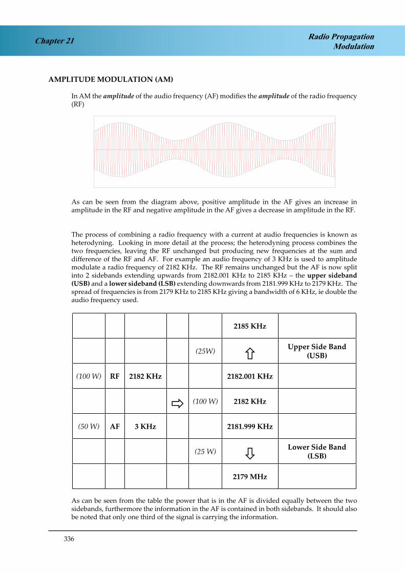
336
Chapter 21 Radio PropagationModulation
AMPLITUDE MODULATION (AM)
In AM the amplitude of the audio frequency (AF) modifies the amplitude of the radio frequency (RF)
As can be seen from the diagram above, positive amplitude in the AF gives an increase in amplitude in the RF and negative amplitude in the AF gives a decrease in amplitude in the RF.
The process of combining a radio frequency with a current at audio frequencies is known as heterodyning. Looking in more detail at the process; the heterodyning process combines the two frequencies, leaving the RF unchanged but producing new frequencies at the sum and difference of the RF and AF. For example an audio frequency of 3 KHz is used to amplitude modulate a radio frequency of 2182 KHz. The RF remains unchanged but the AF is now split into 2 sidebands extending upwards from 2182.001 KHz to 2185 KHz – the upper sideband (USB) and a lower sideband (LSB) extending downwards from 2181.999 KHz to 2179 KHz. The spread of frequencies is from 2179 KHz to 2185 KHz giving a bandwidth of 6 KHz, ie double the audio frequency used.
2185 KHz
(25W) Upper Side Band
(USB)
(100 W) RF 2182 KHz 2182.001 KHz
(100 W) 2182 KHz
(50 W) AF 3 KHz 2181.999 KHz
(25 W) Lower Side Band
(LSB)
2179 MHz
As can be seen from the table the power that is in the AF is divided equally between the two sidebands, furthermore the information in the AF is contained in both sidebands. It should also be noted that only one third of the signal is carrying the information.

337
Chapter 21Radio PropagationModulation
SINGLE SIDEBAND (SSB)
There is redundancy in double sideband transmissions in that the information is contained in both the upper and lower sidebands. Additionally, the original RF carrier wave having served its purpose to get the audio information into radio frequencies is now redundant. So it is possible to remove one of the sidebands and the carrier wave because the remaining sideband contains all the information. This is known as single sideband (SSB) operation.
2185 KHz
(25W)(150W)
Upper Side Band (USB)
(100 W) RF 2182 KHz 2182.001 KHz
(100 W) 2182 KHz
(50 W) AF 3 KHz 2181.999 KHz
(25 W) Lower Side Band
(LSB)
2179 MHz
When using sky wave propagation for communication, the differing refraction occurring at different frequencies leads to an increase in distortion if the bandwidth is too large. The ionosphere comprises electrically charged particles which cause high levels of static interference on radio waves, the use of SSB significantly reduces the effect of this interference. The MF & HF frequencies used for long range communication are in great demand, hence the use of SSB transmissions increases the number of channels available. The use of SSB also reduces the amount of power required. Thus the main advantages of SSB are:
Double the number of channels available with double side bandBetter signal/noise ratio (less interference)Less power required hence lighter equipment

338
Chapter 21 Radio PropagationModulation
HF COMMUNICATIONS
Over inhabited land areas VHF communications are ideal for all communications between aircraft and ground. However, until satellite communications are fully implemented, the only means of communication between aircraft and ground when over the oceans, or other uninhabited areas, is either surface wave or skywave. To achieve ranges of 2000 nm to 3000 nm using surface wave would require frequencies at the lower end of LF or the upper end of VLF. The use of these frequencies for aeronautical communications would require relatively complex equipment with the associated weight penalty, and they would be more susceptible to static interference than higher frequencies making them somewhat tedious to use and they would also have very low data rates. Thus, the only practical means of communication over long ranges is skywave (until satellite communications are fully implemented).
The maximum usable frequency (MUF) for a given range will be that of the first returning skywave and this is the ideal frequency for that range because it will have had the shortest path through the ionosphere, and therefore, will have experienced less attenuation and contain less static interference. However, since the ionisation intensity fluctuates, a decrease in ionisation would result in an increase in skip distance and hence loss of signal. So a compromise frequency is used, known as the optimum working frequency (OWF), which by decades of experimentation and experience has been determined to be 0.85 times the MUF.
Since ionisation levels are lower by night than by day it follows that the frequency required for use at a particular range by night will of necessity be less than the frequency required for use by day. A good rule of thumb is that the frequency required at night is roughly half that required by day.
Because skip distance increases as frequency increases, the range at which communication is required will also influence the selection of the frequency to be used. Short ranges will require lower frequencies and longer ranges will require higher frequency.

339
Chapter 21Radio PropagationModulation
A typical example of the sort of problem that may appear is:
An aircraft on a flight from London, UK to New York, USA is in mid-Atlantic at sunrise.The pilot is in communication with the UK on a frequency of 12 MHz.What frequency can the pilot expect to use with the USA?
NIGHT
DAY
SUNRISE
Answer: 6 MHz.
The wave will be refracted half way between the aircraft and the UK, and half way between the aircraft and the USA. Mid way between the aircraft and the UK it is day, so a relatively high frequency will be required. Midway between the aircraft and the USA it is night so a relatively low frequency will be required.
SELCAL
Because the frequencies have transited the ionosphere they will have accumulated a considerable amount of static interference and, because of the long ranges, signals may be received from more than one ground station. Pilots are required to maintain a continuous listening watch when receiving an ATC service, however, these factors combine to make HF frequencies very difficult and stressful to listen to. To reduce the stress experienced by pilots using HF a selective calling system (SELCAL) is installed in HF equipment to alert pilots when ATC wish to communicate.
Each radio fitted with SELCAL has a unique code comprising 4 letters (eg ABCD). When the aircraft is to be flown in an area where HF communications are used, the pilot notifies ATC of the aircraft’s SELCAL code. Then, having made initial contact with ATC and checked that the SELCAL is serviceable, the pilot can rely on ATC using the SELCAL facility to alert him when communication is required by ATC, if the pilot wishes to communicate with ATC then he will just make a call. SELCAL is also available on VHF in some remote areas.

340
Chapter 21 Radio PropagationModulation
FREQUENCY MODULATION (FM)
In FM the amplitude of the AF modifies the frequency of the RF.
Figure 1.17.
The frequency deviation is primarily dependent on the amplitude of the AF; the greater the amplitude the greater the frequency deviation. The frequency of the AF determines the rate of change of frequency within the modulated RF. When used for sound broadcasting the bandwidth permitted by international agreements is 150 KHz, compared to a maximum bandwidth permitted in AM broadcasting of 9 KHz. Hence FM is generally unsuitable for use below VHF because of the bandwidth requirement.
For communications the bandwidth can be considerably reduced whilst still maintaining the integrity of the information, this is known as narrow band FM (NBFM). Typically NBFM systems have a bandwidth of 8 KHz, which is still greater than the 6 KHz permitted for aeronautical communications and the 3 KHz used in HF communications. NBFM is not, at present, used in aviation communications.

341
Chapter 21Radio PropagationModulation
PHASE MODULATION
In phase modulation the phase of the carrier wave is modified by the input signal. There are two cases the first is where the input is an analogue signal when the phase of the carrier wave is modified by the amplitude of the signal. Secondly, with a digital signal it is known as phase shift keying, the phase change reflects a 0 or 1; eg 0° phase shift indicates a zero and 180° phase shift represents a 1. (Note: this is the simplest case as multiple data can be represented by using many degrees of phase shift.)
There are two cases used in navigation systems, MLS and GPS. MLS uses binary phase shift keying, GPS uses differential phase shift keying.
Amplitude Modulation Frequency Modulation Phase Modulation
PULSE MODULATION
Pulse modulation (PM) is used extensively in radar systems and for data exchange in communications systems.
EMISSION DESIGNATORS
In order to easily identify the characteristics and information provided by electronic signals, a list of designators has been devised. They comprise 3 alphanumerics, where the first letter defines the nature of the modulation, the second digit the nature of the signal used for the modulation and the third letter the type of information carried.

342
Chapter 21 Radio PropagationModulation
EMIS
SIO
N C
HA
RA
CTE
RIS
TIC
S
Firs
t Sym
bol
Seco
nd S
ymbo
lTh
ird
Sym
bol
Type
of m
odul
atio
n of
the
mai
n ca
rrie
rN
atur
e of
sig
nals
mod
ulat
ing
the
mai
n ca
rrie
rTy
pe o
f inf
orm
atio
n tr
ansm
itted
NEm
issi
ons
of a
n un
mod
ulat
ed c
arri
er0
No
mod
ulat
ing
sign
alN
No
info
rmat
ion
tran
smitt
ed
AA
mpl
itude
mod
ulat
ion
- Dou
ble
side
band
1
Sing
le c
hann
el c
onta
inin
g qu
antis
ed o
r di
gita
l inf
orm
atio
n w
ithou
t the
use
of a
m
odul
atin
g su
b-ca
rrie
r, ex
clud
ing
time
divi
sion
mul
tiple
x
ATe
legr
aphy
for a
ural
rece
ptio
n
HA
mpl
itude
mod
ulat
ion
- Sin
gle
side
band
, ful
l car
rier
2
Sing
le c
hann
el c
onta
inin
g qu
antis
ed
or d
igita
l inf
orm
atio
n w
ith th
e us
e of
a
mod
ulat
ing
sub-
carr
ier,
excl
udin
g tim
e di
visi
on m
ultip
lex
BTe
legr
aphy
for a
utom
atic
rece
ptio
n
JA
mpl
itude
mod
ulat
ion
- Sin
gle
side
band
– s
uppr
esse
d ca
rrie
r3
Sing
le c
hann
el c
onta
inin
g an
alog
ue
info
rmat
ion
CFa
csim
ile
DD
ata
tran
smis
sion
, tel
emet
ry,
tele
com
man
d
FFr
eque
ncy
mod
ulat
ion
7Tw
o or
mor
e ch
anne
ls c
onta
inin
g qu
antis
ed o
r dig
ital i
nfor
mat
ion
ETe
leph
ony,
incl
udin
g so
und
broa
dcas
ting
GPh
ase
mod
ulat
ion
8Tw
o or
mor
e ch
anne
ls c
onta
inin
g an
alog
ue
info
rmat
ion
FTe
levi
sion
(vid
eo)
9
Com
posi
te s
yste
m w
ith o
ne o
r mor
e ch
anne
ls c
onta
inin
g qu
antis
ed o
r dig
ital
info
rmat
ion,
toge
ther
with
one
or m
ore
chan
nels
con
tain
ing
anal
ogue
info
rmat
ion
WC
ombi
natio
ns o
f the
abo
ve
PSe
quen
ce o
f unm
odul
ated
pul
ses
KSe
quen
ce o
f pul
ses
mod
ulat
ed in
am
plitu
deX
Cas
es n
ot o
ther
wis
e co
vere
dX
Cas
es n
ot o
ther
wis
e co
vere
d

343
Chapter 21Radio PropagationModulation
For example, VHF radio telephony communications have the designation A3E. Reference to the table gives the following breakdown:
A - Amplitude modulation - Double sideband
3 - Single channel containing analogue information
E - Telephony, including sound broadcasting
This means an RF carrier wave is being amplitude modulated with speech
HF radio telephony communications have the designation J3E, this gives:
J – Amplitude modulation – single sideband with suppressed carrier
3 - Single channel containing analogue information
E - Telephony, including sound broadcasting
This means an RF carrier wave is being amplitude modulated with speech then the RF carrier wave is being removed along with one of the sidebands.
It is not necessary to know the details of the table.
Other designators relevant to the equipments discussed in phase 2 are:
ADF N0NA1A or N0NA2AVHF RTF A3EHF RTF J3EVOR A9WILS A8WMarker Beacons A2ADME P0NMLS N0XG1D
With the exception of ADF it is unlikely that knowledge of these designators will be examined.

344
Chapter 21 Radio PropagationModulation

345
Chapter 21Radio PropagationModulation
QUESTIONS
1. The bandwidth produced when a radio frequency (RF) of 4716 KHz is amplitude modulated with an audio frequency (AF) of 6 KHz is:
a. 6 KHzb. 3 KHzc. 12 KHzd. 9 KHz
2. Which of the following statements concerning AM is correct?
a. the amplitude of the RF is modified by the frequency of the AFb. the amplitude of the RF is modified by the amplitude of the AFc. the frequency of the RF is modified by the frequency of the AFd. the frequency of the RF is modified by the amplitude of the AF
3. Which of the following is an advantage of single sideband (SSB) emissions?
a. More frequencies availableb. Reduced power requirementc. Better signal/noise ratiod. All of the above
4. Which of the following statements concerning FM is correct?
a. the amplitude of the RF is modified by the frequency of the AFb. the amplitude of the RF is modified by the amplitude of the AFc. the frequency of the RF is modified by the frequency of the AFd. the frequency of the RF is modified by the amplitude of the AF

346
Radio PropagationModulationChapter 21
ANSWERS
1 C
2 B
3 D
4 D
347
Chapter 22Radio PropagationAntennae
CHAPTER TWENTY TWO
ANTENNAE
Contents
INTRODUCTION . . . . . . . . . . . . . . . . . . . . . . . . . . . . . . . . . . . . . . .349
BASIC PRINCIPLES . . . . . . . . . . . . . . . . . . . . . . . . . . . . . . . . . . . . . .349
LOADED ANTENNAE . . . . . . . . . . . . . . . . . . . . . . . . . . . . . . . . . . . .350
AERIAL FEEDERS . . . . . . . . . . . . . . . . . . . . . . . . . . . . . . . . . . . . . . .350
POLAR DIAGRAMS . . . . . . . . . . . . . . . . . . . . . . . . . . . . . . . . . . . . . .351
DIRECTIVITY. . . . . . . . . . . . . . . . . . . . . . . . . . . . . . . . . . . . . . . . . .352
OTHER SYSTEMS . . . . . . . . . . . . . . . . . . . . . . . . . . . . . . . . . . . . . . .353
RADAR AERIALS . . . . . . . . . . . . . . . . . . . . . . . . . . . . . . . . . . . . . . .354
QUESTIONS . . . . . . . . . . . . . . . . . . . . . . . . . . . . . . . . . . . . . . . . . .357
ANSWERS . . . . . . . . . . . . . . . . . . . . . . . . . . . . . . . . . . . . . . . . . . .358

348
Chapter 22 Radio PropagationAntennae

349
Chapter 22Radio PropagationAntennae
INTRODUCTION
Antennae or aerials are the means by which radio energy is radiated and received. The type of antenna used will be determined by the function the radio system is required to perform. This chapter will look at the principles which are common to all antennae and at the specialities required for particular radio navigation systems.
BASIC PRINCIPLES
There are two basic types of aerial used for receiving and transmitting basic communications, the half-wave dipole and the Marconi or quarter wave aerial.
Figure 3.5. Half Wave DipoleFigure 4.1 Half-Wave Diplole
With the dipole aerial the power is fed to the centre of the aerial and radiates in all directions perpendicular to the aerial. The Marconi aerial is set on, but insulated from, a metal surface which acts as the second part of a dipole, with the radio energy radiating perpendicular to the aerial. Because of the better aerodynamic qualities, Marconi aerials are used on aircraft.
4
For an aerial to operate with maximum efficiency it must be the correct length for the wavelength of the frequency in use. As the names imply the ideal length for an aerial is half or quarter of the wavelength of the frequency being transmitted. However, whilst we regard the speed of propagation of electromagnetic energy as being constant, this is only true in a specified medium. If the energy passes from one medium to another the speed will change. In the case of electromagnetic energy, the denser the medium the slower the speed. This needs to be taken into account in the length of aerials.
The speed of electromagnetic energy in metal is approximately 95% of the free space speed, so our aerial needs to be 95% of half or quarter the wavelength.

350
Chapter 22 Radio PropagationAntennae
Example:What is the optimum length for a Marconi aerial transmitting on a frequency of 125 MHz?
The wavelength is 2.4 m, so 0.95 x λ = 57 cm 4
LOADED ANTENNAE
The wavelengths of aeronautical VHF radio telephony are 2.19 m to 2.54 m which means that for maximum efficiency the aircraft (and ATC) aerial must be adjustable between approximately 52 cm and 60 cm. To achieve maximum efficiency aerials would have to be adjustable in length, which would pose significant technical problems. Furthermore, aircraft aerials are about 20 - 30 cm long, so would operate very inefficiently.
To overcome these problems an aerial loading unit (ALU) is fitted in the circuit between the radio equipment and the aerial. The ALU samples the signal, then through a series of capacitors and resistors balances the signal travelling to/from the aerial to effect maximum aerial efficiency.
AERIAL FEEDERS
The means by which energy is carried between the aerial and transmitter or receiver is dependent on the frequency in use and the power levels. At low and medium frequencies a simple wire is adequate to carry the signal over reasonable distances with little energy loss. As frequency increases the power losses increase and into HF and VHF a twin wire feeder is more efficient. At UHF frequencies, the power losses in these simple feeders becomes unacceptably high and a coaxial cable is required.
Figure 3.10. Radar Antennae
In the upper part of the UHF band and in the SHF and EHF bands the use of dipole or Marconi aerials is precluded because of the high energy losses and the way the energy is produced. At these frequencies a waveguide is used to carry the energy to or from the aerial. The waveguide is a hollow, rectangular metal tube. The internal dimensions of the tube are determined by the frequency in use, being half the wavelength.

351
Chapter 22Radio PropagationAntennae
POLAR DIAGRAMS
A polar diagram is used to show the radiation or reception pattern of an aerial. It is simply a line joining all points of equal signal strength and is generally a plan view perpendicular to the plane of radiation or reception. From here on we will talk about radiation only, but the same principle applies to reception.
A dipole aerial radiates most energy at right angles to the aerial with signal strength decreasing towards the ends of the aerial, where there is no radiation. A three dimensional representation of radiation from such an aerial would be a torus, centred on the centre point of the aerial:
Figure 3.4. Omni Directional Transmitter Polar Diagram
Clearly such diagrams would be cumbersome so a plan view of the plane of radiation is used:
Figure 3.4. Omni Directional Transmitter Polar Diagram

352
Chapter 22 Radio PropagationAntennae
DIRECTIVITY
Many systems require the directional emission or reception of energy, for example; radar, ILS, MLS and many more. How this directivity is achieved depends on the frequency and application.
The simplest way to achieve directivity is to add parasitic elements to the aerial. If we place a metal rod 5% longer than the aerial at a distance of quarter of a wavelength from the aerial and in the same plane as the aerial, it will act as a reflector.
This reflector re-radiates the energy 180° out of phase, the resulting polar diagram is shown above, with no signal behind the reflector and increase signal in front of the aerial.
This process can be taken further by adding other elements in front of the aerial. These elements are known as directors and are smaller than the aerial itself.
All will recognise this as being the type of aerial array used for the reception of television signals. The directors have the effect of focussing the signal into (or out of) the aerial, giving a stronger signal than that which would be generated by a simple dipole.
However, directivity comes with its own price. As can be seen from the diagram, we have produced a strong beam along the plane of the aerial, but have also produced many unwanted sidelobes which would receive (and transmit) unwanted signals. Signals received in these sidelobes produce characteristic ghosting on television pictures, usually caused by reflections from buildings etc. These sidelobes give major problems which have to be addressed in SSR and ILS, and also produce problems in primary radars.

353
Chapter 22Radio PropagationAntennae
OTHER SYSTEMS
The instrument landing system (ILS) uses an extension of this idea to produce the narrow beams of energy required to guide aircraft along the runway centreline. The localiser aerial array which produces this is an array of 16 or 24 aerials placed in line with half wavelength spacing. There is some modification to the way the signal is fed to the aerials but the end result is that two narrow beams of energy are produced which are symmetrical, close to the centreline of the runway:
•
In automatic direction finding (ADF) a loop aerial is used.
NULL
NULL
a) LOOP b) DIPOLE
Figure 4.2 Polar Diagrams of Loop and Dipole AerialsWhen the loop is aligned with the incoming signal then there is a phase difference between the signals in each of the vertical elements of the loop and there will be a net flow of current from the loop. If the loop is placed at right angles to the incoming signal then the induced currents will be equal and will cancel each other out giving a zero output.
The resulting polar diagram will have two distinct nulls which can be used to determine the direction from which the radio wave is coming.

354
Chapter 22 Radio PropagationAntennae
RADAR AERIALS
Radar systems operate in the UHF and SHF bands where waveguides are used to carry the radio energy, and the end of the waveguide is the aerial. Since radar systems are required to be directional the aerial is placed at the focal point of a parabolic reflector and the energy is then focussed into a narrow beam.
Figure 3.10. Radar AntennaeIn principle a very narrow pencil beam should be produced as shown above. However, this does not happen because the focal point is infinitesimally small compared to the opening of the waveguide, so the energy actually diverges slightly.
Figure 8.10 Typical Radiation Pattern
Additionally, this uneven reflection produces sidelobes which contain sufficient energy to give valid returns outside the main beam.
The width of the beam is dependent on the cross-section of the waveguide and the diameter of the reflector. This relationship is:
Beamwidth = 70 x λ
where D is the diameter of the reflector. D
It follows from this formula that to achieve a narrow beam requires either a very large reflector or a very short wavelength, or both. These problems will be discussed further in chapter 11.

355
Chapter 22Radio PropagationAntennae
Another type of radar aerial is the phased array or slotted antenna.
Figure 8.9 Airborne Weather RadarAntenna
This is a flat plate with numerous waveguide size slots cut into it. These slots are fed with the radio energy which forms a narrow beam similar to a parabolic reflector.
Figure 8.9 Airborne Weather RadarAntenna
As can be seen from the diagram the beam is much narrower than that from a parabolic reflector, and with much smaller sidelobes. This means the power requirements for phased arrays is less than that required for parabolic reflectors. Hence the advantages of a slotted antenna over the parabolic reflector are:
Narrow beam ¾Reduced sidelobes ¾Less power required for a given range ¾Narrower pulse ¾Improved resolution ¾

356
Chapter 22 Radio PropagationAntennae

357
Chapter 22Radio PropagationAntennae
QUESTIONS
1. The ideal length for a Marconi aerial for a frequency of 406 MHz is:
a. 36.9 cmb. 35.1 cmc. 17.5 cmd. 18.5 cm
2. A disadvantage of directivity is:
a. reduced rangeb. sidelobesc. phase distortiond. ambiguity
3. Which of the following is not an advantage of a slotted antenna (phase array)?
a. reduced sidelobesb. improved resolutionc. reduced powerd. directivity
4. The ideal length of a half wave dipole for a frequency of 75 MHz is:
a. 1.9 mb. 95 cmc. 3.8 md. 47.5 cm

358
Radio PropagationAntennaeChapter 22
ANSWERS
1 C
2 B
3 D
4 A

359
Chapter 23Radio PropagationOscillators
CHAPTER TWENTY THREE
OSCILLATORS
Contents
PURPOSE . . . . . . . . . . . . . . . . . . . . . . . . . . . . . . . . . . . . . . . . . . . .361
PRINCIPLE OF OPERATION. . . . . . . . . . . . . . . . . . . . . . . . . . . . . . . . .361
TYPES OF OSCILLATORS . . . . . . . . . . . . . . . . . . . . . . . . . . . . . . . . . .362
RESONANT FREQUENCY . . . . . . . . . . . . . . . . . . . . . . . . . . . . . . . . . .362
L.C. OSCILLATOR . . . . . . . . . . . . . . . . . . . . . . . . . . . . . . . . . . . . . . .363
PIEZO-ELECTRIC EFFECT . . . . . . . . . . . . . . . . . . . . . . . . . . . . . . . . . .364
QUARTZ CRYSTAL CONTROLLED OSCILLATOR. . . . . . . . . . . . . . . . . . . .364
BANDWIDTH AND SELECTIVITY . . . . . . . . . . . . . . . . . . . . . . . . . . . . .365
CATHODE RAY TUBE. . . . . . . . . . . . . . . . . . . . . . . . . . . . . . . . . . . . .365
CRT COMPONENTS . . . . . . . . . . . . . . . . . . . . . . . . . . . . . . . . . . . . .366
MICROWAVE OSCILLATORS . . . . . . . . . . . . . . . . . . . . . . . . . . . . . . . .366
KLYSTRON . . . . . . . . . . . . . . . . . . . . . . . . . . . . . . . . . . . . . . . . . . .367
MAGNETRON . . . . . . . . . . . . . . . . . . . . . . . . . . . . . . . . . . . . . . . . .368
QUESTIONS . . . . . . . . . . . . . . . . . . . . . . . . . . . . . . . . . . . . . . . . . .369
ANNEX A . . . . . . . . . . . . . . . . . . . . . . . . . . . . . . . . . . . . . . . . . . . .372
ANNEX B . . . . . . . . . . . . . . . . . . . . . . . . . . . . . . . . . . . . . . . . . . . .373
ANSWERS . . . . . . . . . . . . . . . . . . . . . . . . . . . . . . . . . . . . . . . . . . .374

360
Chapter 23 Radio PropagationOscillators

361
Chapter 23Radio PropagationOscillators
PURPOSE
An oscillator is an electronic circuit designed to produce an AC sinewave. The frequency of this wave ranges from relatively low, a few hundred Herz, to frequencies in the V/UHF band. Specialist oscillators can produce frequencies to the S/EHF band.
Oscillators are used in radio transmitter systems to produce the carrier wave that will carry information from transmitter to receiver.
Oscillators are used in the radio receiver systems to generate a signal which when mixed with the received signal will produce an intermediate frequency which is lower that the received signal and much easier to amplify and process. This is the super-heterodyne principle.
PRINCIPLE OF OPERATION
An oscillator has no input signal but manages to produce an AC oscillating output signal from just a DC supply. It does this by using positive feedback. All oscillators consist of three basic parts:
a frequency determining unit ¾
an amplifier ¾
a positive feedback unit ¾
The principle of operation is shown in figures in Figures 23.1 and 23.2.
Figure 2.1. Oscillator Input and OutputFigure 23.1 Oscillator Input and Output

362
Chapter 23 Radio PropagationOscillators
AMPLIFIERFREQUENCY
DETERMININGCIRCUIT
FEEDBACKNETWORK
(DC SUPPLY NOT SHOWN)
OUTPUT~
Figure 2.2. Principle of an OscillatorFigure 23.2 Principle of an Oscillator
TYPES OF OSCILLATORS
Radio systems use sinusoidal oscillators that produce an output in the form of sine waves. The frequency determining unit may be one of the following types:
LC (inductance -capacitance) ¾RC (resistance - capacitance) ¾Crystal ¾
The LC and crystal oscillators will be discussed in these notes.
RESONANT FREQUENCY
Inductive reactance, XL varies directly with frequency whereas capacitive reactance, XC varies inversely with frequency. If we display XC against frequency on the same graph as XL against frequency, there is a point corresponding to a certain frequency where XL = XC.
Figure 2.3. XL and XC plotted against frequencyFigure 23.3 XL and XC plotted against frequency

363
Chapter 23Radio PropagationOscillators
The frequency where XL=XC is called the resonant frequency (F0).
At this point: 2 π F L = 1
2 π F C
Solving for F we get: f0 = 1
2 π √ L C
At the resonant frequency alone XL = XC and because of the relationship of the currents, they effectively cancel each other. So at the resonant frequency in a parallel LC circuit the current flow increases dramatically as all opposition to current flow has been cancelled.
If an inductor of 5µ H was placed in parallel with a capacitor of 2.5µ F the resonant frequency would be:
Fo = 1 = 1 = 45016 Hz or 45khz 2 π √ L C 2 π √ (5x10-6) x (2.5 x 10-6)
Now let us connect the above LC circuit into a complete oscillator circuit.
Figure 2.4. LC OscillatorFigure 23.4 LC Oscillator
L.C. OSCILLATOR
In the circuit on previous page we have a complete oscillator. This is known as a tuned-collector oscillator. The frequency determining circuit is formed by the parallel connected L1 and C1 (sometimes called a tank circuit).
The amplifier is Transistor TR1 and its job us to make up for losses in the circuit.

364
Chapter 23 Radio PropagationOscillators
Positive feedback is provided by transformer coupling between L1 and L2 to the base of TR1. This positive feedback keeps the circuit oscillating, rather like whipping a top. Left to its own devices a spinning top will soon stop spinning unless energy is applied to it in the correct direction. Energy applied in the wrong direction will stop the spinning i.e. negative feedback.
When the switch SW 1 is closed the transistor conducts and shock excites the L C circuit into oscillation. A portion of the oscillations are coupled via L1 and L2 to the base maintaining the oscillations (positive feedback). The output taken from the collector of TR1 is a sine wave of 45 Khz.
If C1 or L1 were replaced by components of different value the output frequency would change. If C1 was replaced with a variable capacitor we would have a means of easily changing the output frequency of the oscillator.
PIEZO-ELECTRIC EFFECT
A piezo electric crystal is a material that produces an emf if it is subjected to mechanical stress. The emf reverses polarity if the stress is reversed. Conversely the application of a potential difference across the crystal causes a stress in the material according to the polarity of the crystal voltage.
When a quartz crystal has a voltage applied across it, it will vibrate and produce a small electrical AC signal at a frequency that is dependent upon its thickness (Resonant Frequency).
Using quartz crystals as the frequency determining device in oscillators produce extremely precise stable frequencies. They are particularly used for producing frequencies at VHF and above.
QUARTZ CRYSTAL CONTROLLED OSCILLATOR
The crystal acts as both the frequency determining circuit as well as providing the positive feedback. Whereas the output frequency of a LC oscillator may drift with temperature variations as the device warms up, a crystal controlled oscillator is extremely stable. The disadvantage is that we cannot easily change the frequency as we could in a LC oscillator. Modern developments have overcome this minor drawback.
Figure 2.5 Crystal Controlled OscillatorFigure 23.5 Crystal Controlled Oscillator

365
Chapter 23Radio PropagationOscillators
BANDWIDTH AND SELECTIVITY
The figures below show the frequency response of two LC tuned circuits with the same resonant frequency, f0 Frequencies f1 and f2 occur at 0.707 Vp which is known as the half power or -3dB points. They give us the bandwidth for the circuit, which is f2 -f1. It can be seen that circuit (B) has a larger bandwidth than circuit (A).
Selectivity is the ability of a tuned in a receiver to differentiate between adjacent stations. It can be seen that a circuit with a narrow bandwidth will have a higher selectivity.
Figure 2.6 Bandwidth for LC tuned CircuitsFigure 23.6 Bandwidth for LC tuned Circuits
CATHODE RAY TUBE
SCREEN
X-PLATES
Y-PLATES
HEATINGCOIL
CATHODE(zero voltage)
GRID(variable around
- 50volts)
1st ANODE(+2000 volts)
2nd ANODE(variablearound
+1500 volts)
3rdANODE(around
+4000 volts)GRAPHITE
LINING
DISPLAY
ELECTRONBEAM
Mu METALSCREENING
FLUORESCENTSCREENBACKING
EMISSION ACCELERATION &FOCUSSING
DEFLECTION
ELECTRONGUN
ANODE SYSTEM DEFLECTORPLATES
Figure 2.7 An Electrostatic Cathode ray Tube.Figure 23.7 An Electrostatic Cathode ray Tube

366
Chapter 23 Radio PropagationOscillators
Description. A Cathode Ray Tube (CRT) is an evacuated glass tube in which a controllable beam of electrons is produced and directed on to a screen to give a visible display. The tube may be of the electrostatic or the electromagnetic type.
Applications. CRT’s are used as displays in radar systems to give a circular presentation on plan position indicator (PPI) or a rectangular display when used in computerised radar systems. The television screen is also part of a CRT.
CRT COMPONENTS
The Electron Gun. This is made up of the heater cathode and the grid. The cathode consists of a small cylinder inside which is a low voltage heater. One end of the cylinder is covered in a barium salt; when heated this emits electrons. The grid is a metal cylinder surrounding the cathode and is always more negatively charged than the cathode. Thus the electrons emanating from the cathode are repelled from the grid walls and form a concentrated narrow beam.The negative potential of the grid can be varied to control the number of electrons passing through it to give brilliance control. To increase the brilliance the negativity is decreased. If the grid is made too negative the flow of electrons ceases and the beam is cut-off.
Anode System. From Figure 2.7. it can be seen that the anode system accelerates the electron beam along the tube, because it is highly positive in respect to the cathode. It also controls the focus by adjusting the potential of the second anode.
Deflection System. The electrostatic system uses deflection plates inside the tube whereas the electromagnetic system uses coils wrapped round the outside of the tube. In the electrostatic system, varying potential on the plates causes the electron beam to deflect horizontally and vertically to ‘paint’ a picture on the screen by moving the electron ‘spotlight’ across the screen.
Flourescent Screen. The inside of the screen is coated with a flourescent substance which glows when it is bombarded by the electron beam. The colour and persistence of the glow depend upon the substance used. For colour displays three electron beams are used to produce the full range of colours from the three primary colours of Red, Green and Blue. Three secondary colours are produced by mixing the primary colours as follows:
Red + Green = Yellow (or amber),
Red + Blue = Magenta and
Green + Blue = Cyan.
MICROWAVE OSCILLATORS
Microwave is the general term used to describe radio frequencies higher than 1 Ghz - when the wavelengths can be measured in cms or mms. At such frequencies conventional circuits using transistors become unusable due to radiation losses and increased resistance arising from skin effect.
Klystrons and Magnetrons are two of the devices that can be used for microwave oscillators. They have frequency determining circuits built into the device and work on a different principle to conventional oscillators; they use resonant cavities.

367
Chapter 23Radio PropagationOscillators
The shape of the resonant cavity can be rectangular, spherical or cylindrical. The internal diameter of the cavity which should be half wavelength, determines its resonant frequency. Due to skin effect the currents flow only on the inner surfaces of the cavity. The outer surfaces can therefore be earthed without affecting the cavity operation.
KLYSTRON
The Klystron is a low power oscillator which comprises:
a resonant cavity ¾an electron gun ¾
Figure 2.8 Klystron OscillatorFigure 23.8 Klystron Oscillator
a reflector electrode ¾an output coupling ¾
An arrangement for a klystron oscillator is shown at Figure 23.8.
Electrons generated at the cathode are roughly focussed into a beam by the negative cylindrical grid and the positive cavity acting as an anode. Positive feedback is provided by the electrons which pass through the lips of the cavity and are then reflected back by the negative reflector. The net result is that an oscillation is set up inside the cavity. The frequency is dependent upon the cavity dimensions which can be altered by an adjustable screw.
The resulting currents in the cavity walls can be fed to the output terminal via a coupling loop. Klystrons are used as low power oscillators in radar receivers.

368
Chapter 23 Radio PropagationOscillators
MAGNETRON
For higher power outputs a magnetron is used in microwave oscillators. The magnetron is constructed by making a number of cavities in a solid block of copper. Each cavity oscillates to the same frequency as the others. There several versions of cavities used with the most easily recognisable cavity being the hole and slot type.
The component parts of a magnetron include the anode, the cathode the output coupling and also a powerful magnet. The cavity block is placed inside the poles of the magnet as shown in Figure 23.9.
Electrons emitted by the cathode travel in complicated circular orbits and may return to the cathode. Oscillations are set up in the cavities and a coupling to one of the cavities provides the means of extracting the radio energy via co-axial feed connected to a waveguide.
Magnetrons are used as high power oscillators in Radar transmitters.
Figure 2.9 Cross-Section of a Typical MagnetronFigure 23.9 Cross-Section of a Typical Magnetron

369
Chapter 23Radio PropagationOscillators
QUESTIONS
1. The purpose of a basic Oscillator is to:
a. amplify a signalb. attenuate a signalc. produce a sine wave from a DC inputd. increase the frequency of a sine wave
2. A basic oscillator consists of
1. amplifier2. positive feedback path3. negative feedback path4. frequency determining circuit5. DC supply6. AC supply
a. 1, 3, 4, 5.b. 1, 2, 4, 5.c. 1, 3, 4, 6.d. 1, 2, 3.
3. An electrical resonant circuit is constructed from:
a. esistors and inductors in seriesb. inductors and resistors in series or parallelc. nductors and resistors always in paralleld. apacitor and inductor which may be in parallel or series
4. When a parallel inductive capacitive circuit is operating at its resonant frequency:
a. capacitive reactance is greater than inductive reactanceb. inductive reactance is greater than capacitive reactancec. inductive reactance equals capacitive reactance and a large circulating current existsd. inductive reactance equals capacitive reactance and zero current flows in the circuit
5. Capacitive reactance:
a. decreases as frequency increasesb. increases as frequency increasesc. remains constant with changes in frequencyd. remains constant up to approximately 30MHz and then decreases with increasing
frequency
6. Inductive reactance:
a. decreases as frequency increasesb. increases as frequency increasesc. remains constant with changes in frequencyd. effectively falls to zero at VHF and above

370
Radio PropagationOscillatorsChapter 23
7. In a LC circuit the frequency where XL = XC is called:
a. Impedance (Z)b. Cancellation pointc. Oscillation frequency (F0)d. Resonant frequency (F0)
Look at the circuit at annex A and answer the following 3 questions
8. Which components form the resonant circuit and control the frequency of operation:
1. C12. L13. TR14. L25. C2
a. 1 and 2 onlyb. 1, 2, 3, 5.c. 2, 3, 4, 5.d. 3 only
9. The NPN transistor TR1 is necessary to:
a. form the positive feedback path to maintain oscillationsb. act as the frequency controlling devicec. act as an amplifier and make up for losses in the circuitd. form the negative feedback path to maintain oscillations
10. Positive feedback in the circuit:
a. is provided by transistor TR1b. is provided by transformer coupling between L1 and L2c. is not necessary, the oscillations are maintained by negative feedbackd. is determined by the ratio of C1 to L1
11. In the circuit at Annex A it is necessary to make the output frequency variable. This could be achieved by:
a. replacing C1 with a variable capacitorb. placing a variable resistor in the emitter of TR1c. increasing the turns ratio of L1 - L2d. making the gain of transistor TR1 variable
12. The Piezo electric effect is:
a. the resonation when XL = XCb. the generation of sine waves by an oscillatorc. a quartz crystal vibrating at a frequency dependent on its thickness when an EMF is
applied to itd. a quartz crystal vibrating at a frequency dependent on the size of the EMF applied to
it

371
Chapter 23Radio PropagationOscillators
13. Look at the circuit at Annex B. This shows:
a. an audio frequency amplifierb. a radio frequency amplifierc. crystal controlled oscillatord. a LC controlled oscillator
14. The advantages of a crystal controlled oscillator over a LC controlled oscillator include:
1. cheapness of construction2. precise stable frequency output3. Very narrow bandwidth4. frequency can easily be changed
a. 2 and 3 onlyb. 1, 2, and 3c. 1, 3, and 4d. there are no particular advantages
15. The output frequency of a magnetron depends on:
a. the voltage applied to the cathodeb. the voltage applied to the anodec. the size of the cavitiesd. the material from which the cavities are constructed
16. To produce frequencies in the SHF (microwave) band which of the following could be used:
1. LC oscillator2. Crystal oscillator3. Magnetron4. Klystron
a. 1 and 2 onlyb. 2, 3, and 4c. 3 and 4 onlyd. 3 only
17. Oscillations in a magnetron are maintained by:
a. electrons under the influence of a magnetic field energising the cavitiesb. electrons under the influence of an electrostatic field creating negative feedback to the
cavitiesc. electromagnetic coupling between anode and cathoded. electromagnetic coupling between heater and cathode
18. The high power pulse of a ground radar system is most likely to be produced by:
a. crystal oscillatorb. klystronc. klystron followed by a power amplifierd. magnetron

372
Radio PropagationOscillatorsChapter 23
ANNEX AANNEX A
ANNEX B

373
Chapter 23Radio PropagationOscillators
ANNEX B
ANNEX A
ANNEX B

374
Radio PropagationOscillatorsChapter 23
ANSWERS
1 C 11 A
2 B 12 C
3 D 13 C
4 C 14 A
5 A 15 C
6 B 16 C
7 D 17 A
8 A 18 D
9 C
10 B