oxy-fuel combustion boiler for co capturing: 50 kw-class ...°±... · boundary condition is...
TRANSCRIPT

Journal of Mechanical Science and Technology 24 (10) (2010) 2135~2141
www.springerlink.com/content/1738-494x DOI 10.1007/s12206-010-0711-y
Oxy-fuel combustion boiler for CO2 capturing:
50 kW-class model test and numerical simulation† Joon Ahn1,*, Hyouck Ju Kim2 and Kyu Sung Choi2
1School of Mechanical Engineering, Kookmin University, Seoul 136-702, Korea 2Korea Institute of Energy Research, Daejeon 305-343, Korea
(Manuscript Received August 27, 2009; Revised May 17, 2010; Accepted June 10, 2010)
----------------------------------------------------------------------------------------------------------------------------------------------------------------------------------------------------------------------------------------------------------------------------------------------
Abstract A novel oxy-fuel burner was devised and integrated into a 50 kW-class furnace-type boiler system. A series of experiments was con-
ducted to verify its feasibility for industrial applications. Additionally, numerical simulations were performed and the results validated against experimental data on the detailed physics inside the conventional-design combustion chamber. The oxy-fuel burner, with the help of gas radiation, could effectively heat the combustion chamber. The composition of the exhaust gas revealed that the sealing of the sys-tem is crucial to the achievement of high CO2 concentrations and low NOx emissions.
Keywords: Oxy-fuel combustion; Boiler; Burner; CO2 Capturing ---------------------------------------------------------------------------------------------------------------------------------------------------------------------------------------------------------------------------------------------------------------------------------------------- 1. Introduction
Carbon dioxide (CO2) emissions from the combustion of fossil fuels are significant sources of global warming and cli-mate change. In Korea, industrial boilers’ consumption is around 25% fossil fuel, and so are recognized as the major source of CO2. Several remedies exist for cutting CO2 emis-sions. Improved boiler efficiency is one, though the current state of the art yields boiler efficiencies of over 80%, which does not leave much room for CO2-reduction improvement. In response to this limitation, CO2 capture and sequestration from
flue-gas has emerged as an alternative solution [1]. Currently, there are two distinct approaches to this goal.
The first utilizes a chemical sorbent such as amine to scrub CO2 from the flue gas. The second adopts oxy-fuel combus-tion, which uses oxygen as the oxidizer instead of air [2]. The main composition elements of flue gas from oxy-fuel combus-tion typically are CO2 and water vapor; this makes possible water condensation, which is an economical means of CO2 capture.
Oxy-fuel allows for much faster flame propagation and a slower flow rate for a given amount of fuel. This results in both a smaller flame size and a higher flame temperature [3]. However, there is need of a measure for protecting the system, including the burner, from high temperatures.
The present study devised a coaxial jet-type burner for con-trol of flame volume (Fig. 1). The design helps also to main-tain a uniform temperature in the combustion chamber, which feature is especially relevant to oxy-fuel combustion. The burner’s unique feature is its applicability to both oxy-fuel and air combustion, by means of nozzle positioning [4]. For the purposes of the present study, the burner was integrated into the boiler system illustrated in Fig. 2. The 50 kW-class pilot-scale furnace-type boiler system was investigated preparatory to development of a full-scale industrial boiler. The exhaust gas recirculation and condensing heat exchanger components shown in Fig. 2(a) in fact were not included in the system studied, but will be explored, with a 0.5 MW-class facility, in the next phase of investigation.
As already noted, the present study focused on the combus-tion characteristics of an oxy-fuel burner inside the the com-bustion chamber of a 50 kW-class boiler. A series of experi-ments were conducted in acquiring flame images and analyz-ing the flue-gas composition. Additionally, a numerical simu-lation was performed to explore the possibilities of the system design and to understand the detailed physics inside the com-bustion chamber. Here, in this paper, the combustion charac-teristics of the oxy-fuel burner are discussed, as based on the experimental and numerical results. Then, the validity of the numerical model is examined by comparing it with the ex-perimental results. Finally, design points of the system for achievement of a high-performance CO2-capturing boiler are proposed.
† This paper was recommended for publication in revised form by Associate EditorOhchae Kwon
*Corresponding author. Tel.: +82 2 910 4833, Fax: +82 2 910 4839 E-mail address: [email protected]
© KSME & Springer 2010

2136 J. Ahn et al. / Journal of Mechanical Science and Technology 24 (10) (2010) 2135~2141
2. Experimental apparatus and numerical method
2.1 Experimental apparatus
The experimental setup as designed integrates the oxy-fuel burner (Fig. 1) into the boiler system for the purpose of cap-turing CO2 (Fig. 2(b)). Natural gas, supplied to the burner via a filter, was used as the fuel. The burner, as shown in Fig. 1(a), is coaxial, which type, by positioning of its fuel nozzle, can be made compatible with either oxy-fuel combustion or conven-tional air combustion [4]. Oxygen, as shown in Fig. 2(b), is supplied to the burner by way of an evaporator. The exit of the burner is connected to the combustion chamber of the boiler. A small quartz window was installed on one side of the cham-ber to capture flame images, which were recorded by a video camera (SONY, TRV-30) during the experiment.
The boiler is the furnace type, composed of a combustion chamber and a water-evaporation jacket. The two evaporating jackets are aligned in series in the streamwise direction, as illustrated in Fig. 2(b). Thermocouples are installed inside the combustion chamber to provide the temperature profile along the center line of the chamber. R-type thermocouples, which can measure temperatures up to 1450oC, are installed at the upstream chamber. The tolerance is ±2.5oC when the tem-perature is 1000oC. At the downstream chamber, conventional K-type thermocouples measure temperatures less than 900oC. the tolerance here is within ±3oC for the typical measuring temperature, 600oC.
The flue gas is sampled at the exit of the boiler for analysis of its composition. The sampled gas is supplied to a gas ana-lyzer (SIEMENS: Ultramat 23) by way of a moisture trap. The gas analyzer provides the dry-based volume concentrations of O2, CO2, CO and NO. The uncertainties listed in the test cer-tificate are ±0.2% for the O2 and CO2 components. The
maximum uncertainties for CO and NO concentrations are estimated as 7.6 and 7.3 ppm, respectively, for the measuring span adopted in the present experiment. A control system was installed to monitor the flame and the boiler operation and to shut off the fuel supply when necessary.
2.2 Numerical method
The computational domain included the burner and the combustion chamber of the boiler, as shown in Fig. 3(a). The geometry chosen modeled the 50 kW-class oxy-fuel boiler system developed for the present study. Since the domain did not include the flue-gas duct, an artificial tapered exit was added to minimize the back flow where the pressure outlet boundary condition is imposed. No-slip boundary conditions are imposed on the solid walls. The velocities at the inlet of the burner and the exit of the nozzle, as prescribed for the O2 concentration of exhaust gas to be 2% at the exit of the do-main. Tangential velocity was imposed on the oxidizer side to mimic swirl. The swirl angle was 45o, yielding the swirl num-ber 1.17. The temperatures of the supplied fuel and air were both set at 300 K. The wall of the combustion chamber was set at 500 K in consideration of the working pressure of the
Fuel
Primaryoxidizer
Secondaryoxidizer
Cooling waterinlet
Cooling wateroutlet
(a)
Cooling water jacket
Fuel
Secondary oxidizer nozzle
Swirler
Guide vane
Primaryoxidizer
(b) (c) Fig. 1. Oxy-fuel/air combustion convertible burner [4]: (a) schematic; (b) oxy-fuel mode; (c) air combustion mode.
(a)
(b) Fig. 2. Oxy-fuel boiler system for CO2 capturing: (a) concept; (b) schematic diagram of experimental setup.
J. Ahn et al. / Journal of Mechanical Science and Technology 24 (10) (2010) 2135~2141 2137
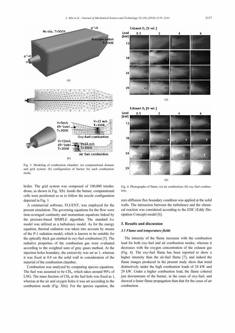
boiler. The grid system was composed of 100,000 tetrahe-drons, as shown in Fig. 3(b). Inside the burner, computational cells were positioned so as to follow the nozzle configuration depicted in Fig. 1.
A commercial software, FLUENT, was employed for the present simulation. The governing equations for the flow were time-averaged continuity and momentum equations linked by the pressure-based SIMPLE algorithm. The standard k-ε model was utilized as a turbulence model. As for the energy equation, thermal radiation was taken into account by means of the P-1 radiation model, which is known to be suitable for the optically thick gas emitted in oxy-fuel combustion [5]. The radiative properties of the combustion gas were evaluated according to the weighted sum of gray gases method. At the injection holes boundary, the emissivity was set as 1, whereas it was fixed at 0.8 on the solid wall in consideration of the material of the combustion chamber.
Combustion was analyzed by computing species equations. The fuel was assumed to be CH4, which takes around 90% of LNG. The mass fraction of CH4 at the fuel hole was fixed as 1, whereas at the air and oxygen holes it was set according to the combustion mode (Fig. 3(b)). For the species equation, the
zero diffusion flux boundary condition was applied at the solid walls. The interaction between the turbulence and the chemi-cal reaction was considered according to the EDC (Eddy Dis-sipation Concept) model [6].
3. Results and discussion
3.1 Flame and temperature fields
The intensity of the flame increases with the combustion load for both oxy-fuel and air combustion modes, whereas it decreases with the oxygen concentration of the exhaust gas (Fig. 4). The oxy-fuel flame has been reported to show a higher intensity than the air-fuel flame [7], and indeed the flame images produced in the present study show that trend distinctively under the high combustion loads of 24 kW and 29 kW. Under a higher combustion load, the flame cohered just downstream of the burner, in the cases of oxy-fuel, and showed a faster flame propagation than that for the cases of air combustion.
(a)
(b) Fig. 3. Modeling of combustion chamber: (a) computational domain and grid system; (b) configuration of burner for each combustion mode.
(a)
(b) Fig. 4. Photographs of flame; (a) air combustion; (b) oxy-fuel combus-tion.

2138 J. Ahn et al. / Journal of Mechanical Science and Technology 24 (10) (2010) 2135~2141
The temperature along the centerline of the combustion chamber decreased sharply upstream and moderately down-stream for both combustion modes, as shown in Fig. 5. The temperature profile of the air combustion case (Fig. 5(a)) shows a point of inflection around x = 0.5 m, under the high combustion loads of 24 kW and 29 kW. This inflection point corresponds to the connection between the two furnaces in series, as shown in Fig. 2, where there is no water jacket. This inflection point was not observed in the other low-flow-rate cases.
Oxy-fuel combustion yields higher temperatures (Fig. 5(b)) than conventional air combustion at the upstream furnace (x < 0.5 m), due to its higher adiabatic flame temperature. The temperatures decrease more rapidly in the streamwise direc-tion, becoming comparable to those of air combustion at the exit of the combustion chamber. This implies that the heat absorbed at the combustion chamber also is comparable to that in the case of air combustion. The excess oxygen concen-tration, which represents the oxidizer-fuel ratio, does not dras-tically affect the temperature field in the dry-based range from
0.5 to 6% (Fig. 6). The temperature profiles predicted by the numerical simula-
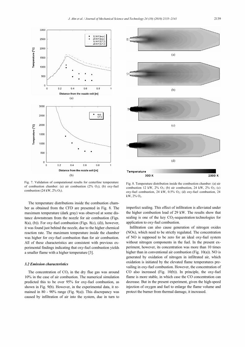
tions were compared with the experimental data (see Fig. 7). The computed temperatures were higher than the measured ones (depicted as symbols) for both air and oxy-fuel combus-tion. This discrepancy is supposed to arise mainly from the thermal boundary condition on the wall and the radiation model. The P-1 model for example, which was adopted in the present study, is known to overpredict the temperature when there is a local heat source [5].
Overprediction was alleviated under the higher combustion load of 24 kW (compared with the 12 kW load in the case of air combustion (Fig. 7(a)). A higher combustion load should increase the optical thickness inside the combustion chamber, which determines that the P-1 model predicts the radiative heat transfer more accurately [5]. The numerical simulation for oxy-fuel combustion (Fig. 7(b)) showed a better agreement with the experiment than that for air combustion. This result supports the above assertions concerning the accuracy of the P-1 model.
(a)
(b)
Fig. 5. Temperature along streamwise centerline of combustion cham-ber with exhaust O2 concentration of 2%: (a) air combustion; (b) oxy-fuel combustion.
(a)
(b)
Fig. 6. Temperature along streamwise centerline of combustion cham-ber with combustion load of 24 kW: (a) air combustion; (b) oxy-fuel combustion.
J. Ahn et al. / Journal of Mechanical Science and Technology 24 (10) (2010) 2135~2141 2139
The temperature distributions inside the combustion cham-ber as obtained from the CFD are presented in Fig. 8. The maximum temperature (dark gray) was observed at some dis-tance downstream from the nozzle for air combustion (Figs. 8(a), (b)). For oxy-fuel combustion (Figs. 8(c), (d)), however, it was found just behind the nozzle, due to the higher chemical reaction rate. The maximum temperature inside the chamber was higher for oxy-fuel combustion than for air combustion. All of these characteristics are consistent with previous ex-perimental findings indicating that oxy-fuel combustion yields a smaller flame with a higher temperature [3].
3.2 Emission characteristics
The concentration of CO2 in the dry flue gas was around 10% in the case of air combustion. The numerical simulation predicted this to be over 95% for oxy-fuel combustion, as shown in Fig. 9(b). However, in the experimental data, it re-mained in 80 - 90% range (Fig. 9(a)). This discrepancy was caused by infiltration of air into the system, due in turn to
imperfect sealing. This effect of infiltration is alleviated under the higher combustion load of 29 kW. The results show that sealing is one of the key CO2-sequestration technologies for application to oxy-fuel combustion.
Infiltration can also cause generation of nitrogen oxides (NOx), which need to be strictly regulated. The concentration of NO is supposed to be zero for an ideal oxy-fuel system without nitrogen components in the fuel. In the present ex-periment, however, its concentration was more than 10 times higher than in conventional air combustion (Fig. 10(a)). NO is generated by oxidation of nitrogen in infiltrated air, which oxidation is initiated by the elevated flame temperatures pre-vailing in oxy-fuel combustion. However, the concentration of CO also increased (Fig. 10(b)). In principle, the oxy-fuel flame is more stable, in which case the CO concentration can decrease. But in the present experiment, given the high-speed injection of oxygen and fuel to enlarge the flame volume and protect the burner from thermal damage, it increased.
(a)
(b)
(c)
(d)
Fig. 8. Temperature distribution inside the combustion chamber: (a) air combustion 12 kW, 2% O2; (b) air combustion, 24 kW, 2% O2; (c) oxy-fuel combustion, 24 kW, 0.5% O2; (d) oxy-fuel combustion, 24 kW, 2% O2.
(a)
(b)
Fig. 7. Validation of computational results for centerline temperature of combustion chamber: (a) air combustion (2% O2); (b) oxy-fuel combustion (24 kW, 2% O2).

2140 J. Ahn et al. / Journal of Mechanical Science and Technology 24 (10) (2010) 2135~2141
The NO and CO concentrations, converted into their respec-tive emission amounts per unit-fuel supply, are summarized in Table 1. The renormalized amounts for oxy-fuel combustion, with the help of a significantly reduced total flow rate, were expected to be comparable to those for air combustion, though the concentrations in the flue gas were much higher. The NO emission per unit-fuel consumption of oxy-fuel was still 50 to 70% more, according to the combustion load, than in air com-bustion. The CO emission for oxy-fuel combustion on the
renormalized unit-fuel-consumption-based scale, however, decreased to 45% of the air combustion case under the com-bustion load of 29 kW.
The heat balances at the boiler, as evaluated, are summa-rized in Table 2. The heat carried by the exhaust gas was less than 5% of the heating value in all of the cases. By adopting oxy-fuel combustion, the exhaust heat, comparing the two systems’ relevant figures under the several combustion loads, was decreased by more than 30%. This illustrates quite em-
Table 1. Pollutants emission.
NO (mg/Nm3 fuel) CO (mg/Nm3 fuel) Load (kW)
Air Oxy-fuel Air Oxy-fuel
12 1,137 1,795 761 605
18 747 1,369 502 360
24 796 1,222 411 228
29 779 1,193 411 180
Table 2. Heat carried by exhaust gas at 3% O2. Mode Load Air Combustion Oxy-fuel Combustion
12 kW 3.27% 1.26%
18 kW 4.33% 1.27%
24 kW 4.37% 1.28%
29 kW 4.41% 1.30%
(a) (b) Fig. 9. CO2 concentration: (a) of exhaust gas (experiment); (b) in combustion chamber (CFD: 24 kW, 2% O2).
(a) (b) Fig. 10. Emission characteristics: (a) NO concentration; (b) CO concentration.
J. Ahn et al. / Journal of Mechanical Science and Technology 24 (10) (2010) 2135~2141 2141
phatically the possibility that boiler efficiency can be en-hanced by properly implementing oxy-fuel combustion tech-nology.
4. Conclusions
We devised a novel 50 kW-class oxy-fuel/air combustion convertible burner and integrated it into a furnace-type boiler system. We conducted experiments on the system’s combustion and heat transfer capabilities and also performed numerical simu-lations of combustion chamber operation. Some of the more noteworthy conclusions are summarized as follows. (1) The oxy-fuel yields a smaller flame with a higher temperature,
which flame, with the help of gas radiation, can heat a rather large combustion chamber designed for a conventional burner.
(2) The sealing of the system was found to be crucial to CO2
capture and sequestration in oxy-fuel combustion. (3) The simulations overpredicted the temperature inside the
combustion chamber, which discrepancy was attributed to the thermal radiation model and thermal boundary condition employed.
(4) The thermal efficiency of an industrial boiler can be en-hanced by adopting oxy-fuel combustion, owing to the de-creased amount of thermal energy carried by the exhaust gas and the significantly reduced flow rate.
Acknowledgments
The authors acknowledge the support of the Energy Tech-nology R&D Program of the Korea Ministry of Knowledge Economics as well as that of Research Program 2010 of Kookmin University, Korea.
References
[1] H. J. Kim, Boiler technology: State of the art on the U.S. DOE industrial combustion roadmap, ETIS 25 (2005) 69-77.
[2] Y. Tan, M. A. Douglas and K. V. Thambimuthu, CO2 cap-ture using oxygen enhanced combustion strategies for natu-ral gas power plants, Fuel 81 (2002) 1007-1016.
[3] H. J. Kim, W. Y. Choi, S. H. Bae and H. D. Shin, Oxy-fuel and flue gas recirculation combustion technology: a review, Transactions of KSME (B) 32 (2008) 729-753.
[4] H. J. Kim, K. S. Choi, S. S. Lee and D. S. Noh, Oxy-fuel / air combustion convertible burner, Korea Patent No. 10-0599381 (2006).
[5] R. Siegel and J. R. Howell, Thermal Radiation Heat Trans-fer, Hemisphere (1992).
[6] F. Breussin, N. Lallemant and R. Weber, Computing of oxy-natural gas flames using both a global combustion scheme and a chemical equilibrium procedure, Combustion Science and Technology 160 (2000) 369-397.
[7] H. K. Kim, Y. M. Kim, S. M., Lee and K. Y. Ahn, Studies on combustion characteristics and flame length of turbulent oxy-fuel flames, Energy and Fuel 21 (2007) 1459-1467.
[8] S. S. Hwang and J. P. Gore, Characteristics of combustion and radiation heat transfer of an oxygen-enhanced flame burner, Journal of Power and Energy Part A 216 (2002) 379-386.
[9] J. Park, J. S. Park, H. P. Kim, J. S. Kim, S. C. Kim, J. G. Choi, H. C. Cho, K. W. Cho and H. S. Park, NO emission behavior in oxy-fuel combustion recirculated with carbon di-oxide, Energy and Fuel 21 (2007) 121-129.
J. Ahn received his B.S. (1997), M.S. (1999) and Ph.D. (2003) from Seoul Nat’l Univ., Korea. He has been a senior re-searcher at KIER (2006-2010) and is now a faculty member at Kookmin Univ. His research interests include heat transfer and combustion problems in energy system.